
JFB10 - Saw Cotech - Free user manual and instructions
Find the device manual for free JFB10 Cotech in PDF.


| Product Type | Band Saw |
| Brand | Cotech |
| Model | JFB10 |
| Voltage | 230 V AC, 50 Hz |
| Power | 420 W |
| No-Load Speed | 1400 rpm |
| Blade Length | 1783 mm |
| Blade Width | 6–13 mm |
| Blade Speed | 660/960 m/min (two speeds) |
| Table Size | 350 × 330 mm |
| Table Tilt | Yes, for bevel cuts |
| Weight | 35 kg |
| Sound Pressure Level (LpA) | 77.4 dB(A) K: 3 dB |
| Sound Power Level (LwA) | 90.4 dB(A) K: 3 dB |
| Dust Extraction Ports | 2 (for dust extractor connection) |
| Safety Features | No-volt release switch, emergency stop button, blade guards |
| Accessories Included | Rip fence, mitre gauge |
| Blade Tension Adjustment | Manual knob |
| Blade Tracking Adjustment | Tracking knob |
| Drive Belt | Two-speed pulley system (replaceable) |
| Blade Replacement | Tool-free with gloves required |
| Maintenance | Regular cleaning of sawdust, motor air intakes |
| Waste Disposal | Follow local ordinances |
Frequently Asked Questions - JFB10 Cotech
User questions about JFB10 Cotech
0 question about this device. Answer the ones you know or ask your own.
Ask a new question about this device
Download the instructions for your Saw in PDF format for free! Find your manual JFB10 - Cotech and take your electronic device back in hand. On this page are published all the documents necessary for the use of your device. JFB10 by Cotech.
USER MANUAL JFB10 Cotech
natural_image
Line drawing of a mechanical device with ladder and control panel (no text or symbols)
Important!
Read the entire instruction manual carefully and make sure that you fully understand it before you use the equipment. Keep the manual for future reference.
Viktig information:
Original instructions
Bruksanvisning i original
Please read the entire instruction manual before use and save it for future reference. We reserve the right for any errors in text or images and for making any necessary technical changes to this document. If you should have any questions concerning technical problems please contact our Customer Services.
1. Safety
Warning!
In order to minimise the risk of fire, electric shock or personal injury, certain basic safety precautions must always be observed when using this machine. Read this instruction manual carefully before using the product and save this manual for future reference.
- Keep the working area tidy. Cluttered surfaces and benches invite accidents.
- Take stock of your working environment. Do not expose the tool to rain. Do not use the tool in moist or wet areas. Keep the working area well lit. Never operate the tool near flammable liquid or gas.
- Avoid electric shocks. Avoid body contact with earthed objects such as pipes, radiators, ovens or refrigerators.
- Keep other people at a safe distance. Do not allow anyone, especially children, not involved in the work process to touch the tool or its electric cable. Keep all bystanders at a distance.
- Store the tool in a safe place. When your tools are not in use, keep them in a locked, dry area, away from children.
- Do not force the tool. The tool will work better and safer at the feed rate for which it was intended.
- Use the correct machine. Do not try to use small tools to perform jobs requiring more powerful tools. Do not use a tool for a purpose for which it was not designed, e.g. using a circular saw for lopping branches off trees.
- Wear suitable attire. Do not wear loose-fitting clothing or jewellery; they could be caught in moving parts. Non-slip shoes are recommended for outdoor work. Wear a hairnet or similar if you have long hair.
• Always use safetywear. Wear safety glasses. Use a dust mask or dust filter when working in dusty environments.
- Use dust extractors. If the tool is equipped with or connected to a dust extractor/collector, make sure that it is turned on and used correctly.
- Do not abuse the lead. Do not jerk the lead, grip the plug itself when disconnecting the power. Make sure that the mains lead does not come into contact with heat, oil, or sharp edges.
- Firmly secure the workpiece. If possible use vices or clamps to hold the workpiece in place. This is much safer than holding the workpiece in one hand.
- Do not overreach. Make sure that you stand steady and balanced all times.
- Look after you tools. Make sure that they are clean and that the edges are sharp for maximum effect and best results. Follow the manual's recommendations regarding lubrication and replacement of accessories. Inspect the mains lead regularly. If it is damaged it should be replaced by a qualified service technician. Inspect all leads and cables regularly to check for any damage. Make sure that the machine's handles and controls are clean, dry and free from oil and grease.
- Have any defective power switches replaced at a qualified service centre.
- Do not use the product if the ON/OFF switch does not function properly.
- Turn the power off. Pull out the plug and push in the emergency stop button before servicing or changing any blades, drill bits, cutters or sanding discs.
- Remove all spanners and repair tools. Make a habit of checking to make sure that the machine is free of all spanners and tools before turning the power on.
-
Avoid accidental starts. Do not walk around with your finger on the trigger of a power tool if it is plugged in. Make sure that the ON/OFF switch is set to OFF before plugging in any power tool.
-
Use the correct extension leads. If you use extension leads outdoors, only use those designed for outdoor use. Only use extension leads with thick enough diameter core wires and roll out the whole lead.
- Use common sense and be careful. Think before carrying out any task, so that it is carried out safely. Never operate machines/power tools when you are tired or under the influence of medicine.
-
Check the following before turning the tool on:
-
That all guards and other parts are whole and in working order.
- That moving parts are free and correctly aligned.
- That no moving parts can get caught.
- That there are no visible defects.
-
Other factors that can influence work execution.
-
Use only recommended accessories. The use of accessories which are not recommended by the manufacturer may present a risk of personal injury.
- Check that the tool conforms to current safety regulations. Repairs to the tool should only be carried out by a tradesman using original spares; otherwise the tool could cause accidents and personal injury.
Additional safety instructions
- If using a floor stand, make sure that the band saw is securely fastened to the stand and that the stand is properly assembled and securely fastened to the floor.
• Make sure that the band saw is positioned in such a way that the workpiece can be worked on in a safe manner. - This saw must not be used for wet cutting. Doing so can lead to deadly electric shocks. This band saw is only intended for dry cutting.
- The drive belt must not be put under too much tension; it will last longer if the tension is released when the saw is not in use.
- Do not allow the build-up of sawdust around the motor or inside the machine. Piles of sawdust are a fire hazard.
- The sawblade must not be stopped through the exertion of pressure on the workpiece or by apply force to the sides of the blade.
- The machine's safety guards must be in place and functioning properly. Always check that the blade guides are correctly aligned.
- Never turn the machine on if the saw blade is in contact with the workpiece.
- Make sure that there are no nails or screws in the workpiece which could damage the saw blade.
- Do not attempt to modify the machine or its accessories in any way.
- Do not apply too much pressure to the workpiece when feeding it into the saw blade. A steady feed rate reduces wear on the saw and saw blade and consequently increases the efficiency and useful life of the band saw. Replace any worn table inserts.
- Connect the band saw to a dust extractor before starting to saw. The saw must not be used if any of its panels is open or if the blade guard is not in place.
- Select an appropriate saw blade and sawing speed for the type of workpiece.
- When sawing with a tilted table, position the guide on the lower side of the table.
- Position the blade guard as close to the workpiece as possible.
Saw blade safety
- Use only blades recommended by the manufacturer/supplier.
- Do not use a damaged or deformed saw blade. Doing so could result in considerable danger to the user or damage to the machine.
- The direction marked on the saw blade should correspond to the direction of the pulley's rotation.
-
The teeth of the blade should be pointing downwards when the blade is viewed from the side.
-
Release the blade tension when the saw is not used. Always wear safety gloves and safety glasses when fitting or removing a saw blade.
- Always roll up the saw blade in an open area away from other people. Store the blade coiled up and protected with fastening wire.
• Always keep your fingers away from moving saw blades.
Specific safety instructions for band saws
- Never use damaged or deformed saw blades.
- Replace the table insert when it is worn or damaged.
- Do not clean the saw blade whilst it is in motion.
- Connect a dust extraction device to the band saw when sawing wood.
- Do not turn the saw on when one of the blade pulley wheel covers is open or if any of the blade guards are not in place.
- Make sure that you use the correct blade speed for the material that is to be cut.
- When transporting the saw, the upper blade guard should be lowered over the blade to protect it.
- When sawing cylindrical workpieces, a clamp should be used to prevent the workpiece from twisting.
- When sawing tall workpieces, a clamp should be used to prevent the workpiece from tipping over.
- The band saw must only be used with compatible accessories and only for the purpose for which it was designed.
- Do not allow children to use the machine.
The most frequent dangers when band sawing are
- Dangers associated with the moving saw blade, such as sharp teeth.
- Off-cuts from the workpiece which can be ejected towards the user.
- Kickbacks from the workpiece.
Despite the fact that the band saw has been fitted with all the necessary safety devices and conforms to relevant safety standards, the following hazards still exist
• Hearing damage caused by high noise levels.
- The risk of an accident in the unprotected area around the saw blade.
- The risk of injury when changing the saw blade.
- The risk of flying off-cuts or wood chips.
- Trapped fingers.
- Workpiece kickback.
- The risk of inhalation of harmful dust, especially oak and beech sawdust.
Product safety symbols and their meaning

Read the instruction manual carefully before use.

Always use ear protection, eye protection and respiratory protection to prevent inhalation of harmful dust.
2. Buttons and functions

- ON/OFF button
- Rip fence
- Upper pulley wheel cover
- Blade tension knob
- Upper blade wheel cover screw
- Blade guide adjustment knob
- Upper blade guide assembly
- Mitre gauge
- Table
- Dust extraction port (× 2)
- Lower blade pulley wheel cover screw
- Blade tracking knob
- Belt tension
- Motor
- Table trunnion
- Pointer
- Table locking wing nut

3. Assembly
Note! Make sure that the band saw is disconnected from the mains before assembly.
Fitting the table and rip fence
- Fit the table onto the trunnion (15) and secure it using the bolt and wing nut (17).

- Fit the rip fence (2) and its rail onto the table.
Setting up the table
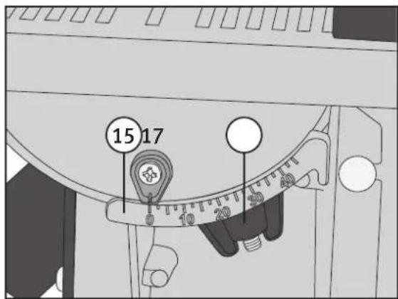
- Loosen the screw that secures the pointer (16) and set the pointer to 0°.
- Place a set square against the table and blade.

natural_image
Mechanical assembly diagram showing a cutting machine with a workpiece and meshing (no text or symbols visible)- Loosen the table locking wing nut (17) and adjust it so that it is at a right angle to the blade. Tighten the wing nut again.
Setting up the blade tension and tracking
- Open the upper and lower pulley wheel covers.
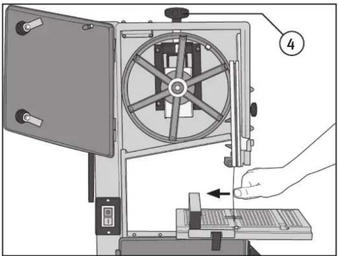
- Adjust the blade tension using the tension knob (4). Turn the knob clockwise to increase the tension, anticlockwise to decrease the tension.
- The saw blade is correctly tensioned if it can be moved approximately 10 mm sideways with moderate hand pressure.
natural_image
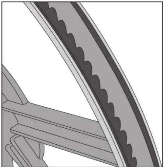
Technical illustration of a mechanical device with a hand operating a tool, showing no text or symbols.- Slowly rotate the upper pulley by hand to make sure that the blade is centred on both of the blade pulley wheels.
natural_image
Close-up of a mechanical gear mechanism with teeth and chain (no text or symbols visible)- If adjustment is necessary, loosen the wing nut on the tracking knob (12) and move the knob in or out until the blade runs true.

natural_image
3D mechanical assembly diagram showing a bolted component with two bolts and a numbered part (12), no text or symbols present.Setting up the blade guides
The blade guides minimise blade movement during sawing.
-
After the blade has been centred on the blade pulley wheels, make sure that the teeth of the blade do not line up with the guide pins (18), if they do the entire guide pin post and support bearings can be moved back so that the teeth of the blade do not foul the guide pins.
-
The guide bearings should be 0.2 mm from the side of the blade.


-
Rotate the wheel by hand and make sure that the joint of the blade passes through the guides.
-
Position the rear support bearing (19) as close to the back of the saw blade as possible without it coming into contact.

4. Operation
Start/stop button
This saw is fitted with a no-volt release switch which prevents the saw from automatically starting again following a power cut or if the mains plug is reconnected to the mains supply after the machine has been stopped by being unplugged with the ON/OFF switch set to ON.
The saw is switched on by pushing in the green [1] button and switched off by pushing in the red [0] button.

natural_image
Close-up of a black electrical switch panel with two buttons and mounting holes (no text or symbols visible)Sawing
- The upper blade guide assembly should be lowered to as close a position to the workpiece as possible. To lower the assembly, loosen the locking knob (6) and slide the assembly down. Tighten the locking knob.
- Set the rip fence to the desired width. Plan the cut before starting to saw. When sawing a small workpiece, use a push stick to ensure that your hands do not come too close to the blade.
- Before sawing a large workpiece, make sure that there is enough room around the saw for the workpiece to be manoeuvred safely. If necessary, you should also make sure that the workpiece is supported to avoid undue stress on the blade. Cut the material at a steady, even pace. A clear sign that the sawing is being forced too quickly is the motor changing pitch or slowing down.

Note
• Make sure that the saw blade undamaged and is centred on the blade pulley wheels before starting to saw.
- Feed the workpiece into the blade carefully making sure not to exert too much pressure.
- Hold the workpiece in both hands if you can or use a push stick if the workpiece is too small.
• Always keep your hands well away from the saw blade and think through the cut before starting.
- For the best results, use a sharp saw blade.
- Select the correct saw blade for the thickness of the workpiece and type of cut. Thin and hard woods require finer toothed blades than thicker, softer woods.
- Tight radii require a narrower blade than straight cuts.
- Use the rip fence as a support when making straight cuts.
- Think about a cut before beginning to saw a workpiece, you might need to reposition the workpiece or turn it over. Mark out the cut on both sides of the workpiece if necessary.
- Never twist the workpiece without it being pressed against the saw blade, otherwise the workpiece can become stuck or the blade can bend.
• Always unplug the band saw before making any adjustments or repairs and whenever the saw is not to be used.
Using the mitre gauge
- Make a practice cut with the gauge set to 0^ and then check the cut using a try square.
- If adjustment is necessary, loosen the screw holding the pointer and move the pointer accordingly.
- Set the desired angle on the mitre gauge and make the cut whilst holding the workpiece firmly against the mitre gauge.

natural_image
Technical illustration of a mechanical protractor with angular measurement scale (no text or symbols)Tilting the table making bevel cuts
- Undo the wing nut (17), tilt the table to the desired angle and tighten the wing nut.

5. Care and maintenance
Changing the saw blade
- Open the upper and lower blade pulley wheel covers.

natural_image
Mechanical assembly diagram showing a cutting machine with a workpiece and a tool inserted into a slot (no text or symbols visible)- Remove the screw from the end of the saw blade.

-
Turn the blade tension knob (4) anticlockwise until the blade comes loose.
-
First put on a pair of work gloves and then carefully remove the blade from the saw, the teeth are very sharp.
- Fit the new blade in reverse order making sure that the teeth are pointing down towards the table.
- Tension the blade as directed in "Setting up the blade tension and tracking".
- If necessary, adjust the blade guides as directed in "Setting up the blade guides".
Changing the speed/drive belt
- Remove the blade; refer to "Changing the saw blade".
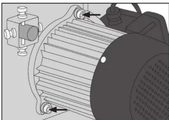
- The motor is fastened by two bolts on the back of the saw.
natural_image
Technical illustration of an electric motor with gear and mounting bracket (no text or symbols)- Undo the two bolts so the motor can be moved and the belt loosened.

natural_image
Mechanical diagram of a wheel with rotating components and directional arrows indicating motion (no text or symbols)- The blade speed can be changed by moving the drive belt between drive pulley wheels. The outer pulley wheels (as in fig.) move the blade at 660 m/min and the inner wheels (see arrows) move the blade at 960 m/min.
natural_image
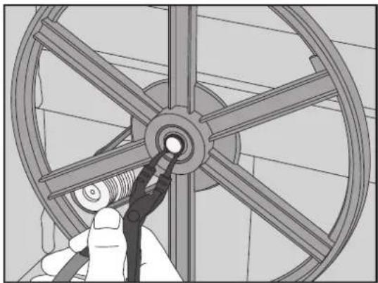
Illustration of a hand using a tool to adjust a wheel rim (no text or symbols visible)- To replace the drive belt the lower blade pulley wheel must be removed. Find the circlip that holds the blade pulley wheel onto the shaft and remove it using a pair of circlip pliers.

natural_image
Mechanical assembly diagram showing a wheel and pulley mechanism (no text or symbols)-
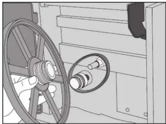
Pull the blade pulley wheel off the shaft.
-
Place the new belt over the motor's drive pulley wheel and round the shaft which the blade pulley wheel is mounted on. Replace the blade pulley wheel and refit the circlip. Make sure that the drive belt is fully located in the grooves of either the inner or outer wheels.
-
Tension the belt by pivoting the motor back into place and secure it with the two bolts.

natural_image
Illustration of a hand connecting a cable to a mechanical component (no text or symbols visible)Note:
- Always unplug the band saw before making any adjustments or repairs and whenever the saw is not to be used.
- Do not expose the machine to moisture.
- Keep the table clean and free of wood sap.
- Keep the band saw clean, use a brush and dust extractor to remove dust and chips. Pay particular attention to the motor's air intakes and any openings where the dust can build up and prevent the blade from running freely.
6. Troubleshooting
| Problem Possible cause Solution | ||
| The machine does not start when the on/off switch is pushed. | No power supply to the wall socket. Check fuses and cables. | |
| Faulty switch. | ||
| One of the covers is open. Close the cover. | ||
| The saw blade does not move when the motor is on. | The blade tension is loose. Turn off the motor and adjust the tension. | |
| The blade has come off one of the pulley wheels. | Open the covers and check. | |
| The saw blade has broken. Replace the saw blade. | ||
| The drive belt has broken. Change drive belt. | ||
| The saw blade does not cut straight. | The cut was done freehand. Use a fence to guide the workpiece. | |
| Feed speed too high. Do not apply so much pressure. | ||
| The saw blade is damaged or blunt. Replace the saw blade. | ||
| The blade guides are not set correctly. | Adjust the blade guides. | |
| The saw blade does not cut or cuts very slowly. | The saw blade is blunt. Change blade (6 TPI* for wood and soft materials, 14 TPI* for hard materials)*TPI= teeth per inch. | |
| Blade fitted upside down. Fit the blade correctly. | ||
| Sawdust builds up inside the machine. | This is completely normal. Clean the saw regularly with a brush and dust extractor. | |
| The saw does not cut at angles of 45° or 90°. | The table is not correctly set in relation to the blade. | Adjust the table. |
| Blunt blade or too high a feed rate. | Replace the blade or reduce pressure on the workpiece. | |
| The saw blade does not align centrally on the blade pulleys. | The blade pulley wheels are not in line, bad bearings. | Contact our Customer Services. |
| The blade pulley wheels are not in line, incorrectly set. | Adjust the alignment using the knob on the back of the saw. | |
| Incorrect blade. | Change blade. | |
7. Waste management
Follow local ordinances when disposing of this product. If you are unsure how to proceed, contact your local authority.
8. Specifications
| Voltage | 230 V AC, 50 Hz |
| Power | 420 W |
| No-load idle speed | 1400 rpm |
| Blade length | 1783 mm |
| Blade width | 6–13 mm |
| Blade speed | 660/960 m/min |
| Table size | 350 × 330 mm |
| Sound pressure (LpA) | 77.4 dB(A) K: 3 dB |
| Sound power (LwA) | 90.4 dB(A) K: 3 d |
| Weight | 35 kg |
Bandsåg 10"
ART.NR 18-3205 MODELL JFB10-UK
40-7894
JFB10
natural_image
Mechanical assembly diagram showing a cutting machine tool interacting with a workbench (no text or symbols visible)natural_image
Technical illustration of a mechanical device with a hand operating a tool, showing no text or symbols.natural_image
Close-up of a mechanical gear mechanism with visible teeth and grooves (no text or symbols)natural_image
3D diagram of a mechanical component with two parts, one showing internal structure and the other part labeled '12' (no text or symbols beyond label)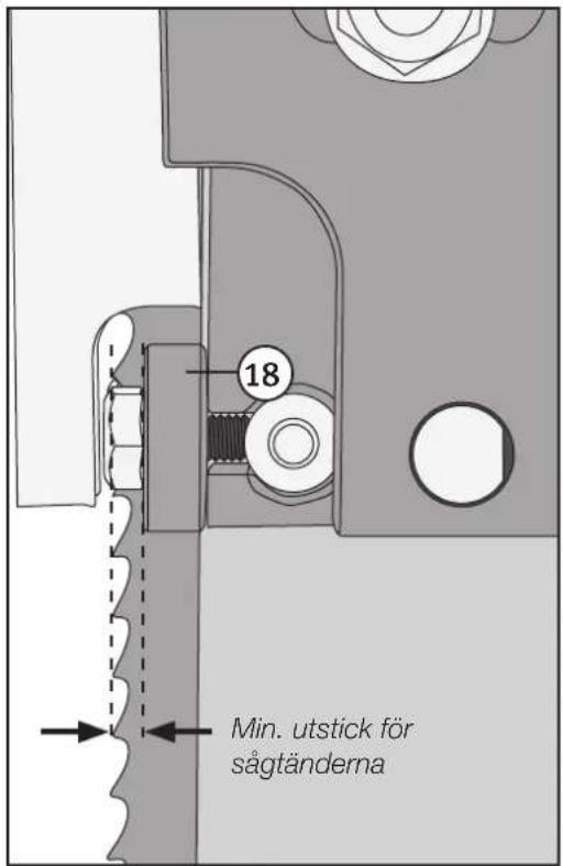
natural_image
Close-up of a black electrical switch panel with two buttons and mounting holes (no text or symbols visible)Sågning
Tänk på att
natural_image
Technical illustration of a mechanical protractor with angular measurement scale (no text or symbols)natural_image
Technical diagram of a mechanical device with a labeled component (17), showing no readable text or symbols beyond the number.natural_image
Mechanical assembly diagram showing a cutting machine with a workpiece and a small component (no text or symbols visible)natural_image
Mechanical assembly diagram showing a motor with rotating shafts and mounting components (no text or symbols)natural_image
Mechanical diagram of a wheel with rotating components and directional arrows indicating motion (no text or symbols)natural_image
Illustration of a hand using a tool to adjust a wheel rim (no text or symbols visible)natural_image
Mechanical assembly diagram showing a wheel and pulley mechanism (no text or symbols)natural_image
Illustration of a hand connecting a cable to a mechanical component (no text or symbols visible)Obs!
natural_image
Technical illustration of a CNC machine tool interacting with a workbench (no visible text or symbols)natural_image
Close-up of mechanical gear teeth and blades (no text or symbols visible)natural_image
3D mechanical assembly diagram showing a bolted component with two flanged parts and a numbered label (12), no readable text or symbols present.natural_image
Close-up of a black electrical switch panel with two buttons and mounting holes (no text or symbols visible)Saging
Husk
natural_image
Technical illustration of a mechanical protractor with angular measurement scale (no text or symbols)natural_image
Mechanical assembly diagram showing a cutting machine with a workpiece and a small component, no visible text or symbols
natural_image
Technical illustration of an electric motor with gear and mounting components (no text or symbols)natural_image
Mechanical diagram of a wheel with six spokes and directional arrows indicating rotation (no text or symbols)natural_image
Illustration of a hand using a tool to adjust a wheel rim (no text or symbols visible)- For å skifte drivreim må man fjerne det nedre sagbladhjulet. Lokaliser låsingen som fester sagbladhjulet på akselen og fjern den med hjelp av en passende låseringstang.
natural_image
Mechanical assembly diagram showing a wheel and pulley mechanism (no text or symbols)natural_image
Illustration of a hand connecting a cable to a mechanical component (no text or symbols visible)Obs!
natural_image
Technical illustration of a CNC machine tool interacting with a workbench (no text or symbols visible)natural_image
Technical illustration of a mechanical device with a hand operating a tool, showing no text or symbols.natural_image
Close-up of a mechanical gear mechanism with visible teeth and grooves (no text or symbols)natural_image
3D mechanical assembly diagram showing a bolted component with two separate parts (no text or symbols)Teräohjaimien säätö

natural_image
Close-up of a black electrical switch panel with two buttons and mounting holes (no text or symbols visible)Sahaaminen
natural_image
Technical illustration of a mechanical protractor with angular measurement markings (no text or symbols)natural_image
Mechanical assembly diagram showing a cutting machine with a workpiece and a small component, no visible text or symbols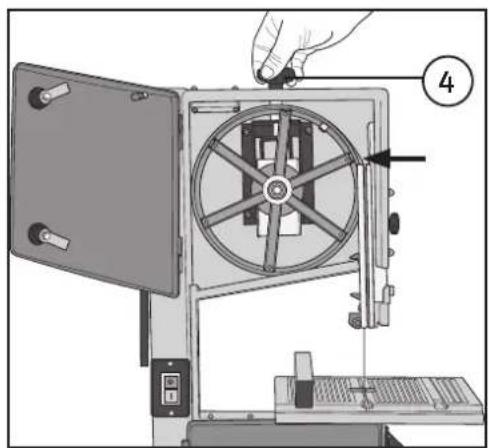
natural_image
Technical illustration of an electric motor with gear and mounting bracket (no text or symbols)natural_image
Mechanical diagram of a wheel with rotating components and directional arrows indicating motion (no text or symbols)natural_image
Illustration of a hand using a tool to adjust a wheel rim (no text or symbols visible)natural_image
Mechanical assembly diagram showing a wheel and pulley mechanism (no text or symbols)natural_image
Illustration of a hand connecting a cable to a mechanical component (no text or symbols visible)Huom.!
natural_image
Mechanical assembly diagram showing a cutting machine tool interacting with a workbench (no text or symbols visible)natural_image
Technical illustration of a mechanical device with a hand operating a tool, showing no text or symbols.natural_image
Close-up of mechanical gear teeth and pulley system (no text or symbols visible)natural_image
3D mechanical assembly diagram showing a bolted component with two separate parts (no text or symbols)natural_image
Close-up of a black rectangular electronic device with two buttons and a vertical indicator (no text or symbols visible)Sägen
Daran denken
natural_image
Technical illustration of a protractor with angular measurement scale (no text or symbols)natural_image
Mechanical assembly diagram showing a cutting machine with a screw and workpiece (no text or symbols visible)natural_image
Technical illustration of an electric motor with gear and mounting bracket (no text or symbols)natural_image
Mechanical diagram of a wheel with rotating components and directional arrows indicating motion (no text or symbols)natural_image
Illustration of a hand using a tool to adjust a wheel rim (no text or symbols visible)natural_image
Mechanical assembly diagram showing a wheel and pulley mechanism (no text or symbols)natural_image
Illustration of a hand connecting a cable to a mechanical component (no text or symbols visible)Achtung:
Declaration of Conformity
EC type certificate, no. M6A 14 05 44390 863
Issued by the following notified body:
10 – 13 Market Place
Kingston Upon Thames
Surrey
KT1 1|Z
DEUTSCHLAND
KUNDENSERVICE

- Safety
- Warning!
- Additional safety instructions
- Saw blade safety
- Specific safety instructions for band saws
- The most frequent dangers when band sawing are
- Despite the fact that the band saw has been fitted with all the necessary safety devices and conforms to relevant safety standards, the following hazards still exist
- Product safety symbols and their meaning
- Buttons and functions
- Assembly
- Fitting the table and rip fence
- Setting up the table
- Setting up the blade tension and tracking
- Setting up the blade guides
- Operation
- Start/stop button
- Sawing
- Note
- Using the mitre gauge
- Tilting the table making bevel cuts
- Care and maintenance
- Changing the saw blade
- Changing the speed/drive belt
- Note:
- Troubleshooting
- Waste management
- Specifications
- Bandsåg 10"
- Sågning
- Tänk på att
- Obs!
- Saging
- Husk
- Teräohjaimien säätö
- Sahaaminen
- Huom.!
- Sägen
- Daran denken
- Achtung:
- Declaration of Conformity
- DEUTSCHLAND
Brand : Cotech
Model : JFB10
Category : Saw