
M-10 - Talkie Walkie MIDLAND - Free user manual and instructions
Find the device manual for free M-10 MIDLAND in PDF.


| Product Type | Two-Way Radio |
| Brand | Midland |
| Model | M-10 |
| Dimensions (H x W x D) | 5.5 x 2.5 x 1.5 inches |
| Weight (with batteries) | Approx. 6 oz (170 g) |
| Power Source | 3 AA alkaline batteries or rechargeable NiMH pack |
| Number of Channels | 22 |
| Frequency Band | UHF 462-467 MHz (FRS/GMRS) |
| Maximum Range | Up to 10-15 miles (depending on conditions) |
| Transmit Power | 0.5 watts (FRS) / 2 watts (GMRS) |
| Key Features | VOX, Scan, Monitor, Keypad Lock, Roger Beep |
| Display | LCD with backlight |
| Battery Life | Approx. 20 hours typical use |
| Charger | Optional desktop charger |
| Included Accessories | Belt clip, antenna |
| Cleaning | Wipe with soft damp cloth; do not use solvents |
| Water Resistance | Not waterproof; keep away from water |
| Safety | Do not disassemble; use only specified batteries |
| Spare Parts | Batteries, belt clip, antenna available from Midland |
| Repairability | Contact Midland support for service |
| Warranty | 1-year limited warranty |
| Compliance | FCC Part 95 |
| Manual | Available for free download in PDF |
Frequently Asked Questions - M-10 MIDLAND
User questions about M-10 MIDLAND
0 question about this device. Answer the ones you know or ask your own.
Ask a new question about this device
Download the instructions for your Talkie Walkie in PDF format for free! Find your manual M-10 - MIDLAND and take your electronic device back in hand. On this page are published all the documents necessary for the use of your device. M-10 by MIDLAND.
USER MANUAL M-10 MIDLAND
- UP/DOWN buttons: channel selection. Short press: increase/decrease of the channel number; long press: quick scroll of the channels.
Note: by switching on the radio and keeping pressed the UP button at the same time, you can enable/disable the keypad beep and the turning on beep.
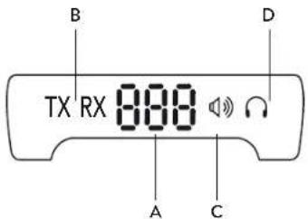
2. Display with backlight
A. Selected channel number
B. RX/TX: reception (RX) and transmission (TX) indicator
C. This icon shows that the internal speaker of the radio is selected. When the icon blinks, M-10 is in "mute" condition (audio off)
D. Shows that you selected, through the AUDIO button, the option of the audio coming from the 3.5mm jack (external headset). When the icon blinks, M. 10 is in "mute" condition (audio off)
Note: when both icons appear on the display, both audio outputs are active (internal speaker and 2pin)
- USB socket: this socket is a 5V power supply source for your devices.
- AUDIO: this button lets you manage the audio of your CB and/or select the desired type of audio: you can choose between the traditional mike or connect an external accessory to the 2pin plug. Briefly press the button to activate/deactivate the radio speaker (MUTE function). The 🔊 Ω icons on the display will blink to indicate the "mute" condition. Keep pressed this control to select the standard microphone and/or the 2pin plug. You can connect to this plug a 2pin MIDLAND headset or the new Midland Bluetooth adaptor WA-DONGLE that lets you use the CB remotely. Go to www.midlandeurope.com to have a look at the Bluetooth devices of the WA line.
- AM/FM (EC/EN): Dual-function selector.
AM/FM: To select AM or FM mode. If you select a frequency band operating in FM mode only, this control enables the LCR function (Last Channel Recall).
EC/EN: when the UK band is selected (UK on the display), move this switch to activate the EN (English) or EC (European) bands.
- 9.NORM.19: the 3-position selector allows to switch from the standard mode (norm) to the 9 and 19 channels that are usually used for emergency communications.
- Squelch knob: to eliminate 'chopping' signals during message reception and to operate in DS mode (Digital Squelch).
- ON/OFF-VOLUME knob: OTT position: transceiver turned off, VOLUME: rotate the knob to select the desired volume level.
- Microphone jack: jack for the mic connector.
- "MIC - SPK" socket: 2Pin MIDLAND socket. You can connect to this plug a Midland headset or earphone/mike to make your conversations "private" and to ensure you won't be heard all around; or you can plug-in the Midland WA-DONGLE adaptor that makes your CB Bluetooth and then choose a Bluetooth earphone/mike of the new WA range to suit your needs.
REAR PANEL
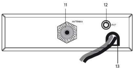
- Antenna connector: PL connector type.
- EXT jack: external loudspeaker jack (if you connect an external speaker, the internal one will be excluded).
- Power supply cable: 12.6 VDC ± 10%.
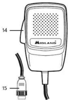
MICROPHONE
- PTT: transmission button
- 4 pin microphone connector
4
M-10 Instruction Guide
INSTALLATION
Safety and convenience are the primary consideration for mounting any piece of mobile equipment. All controls must be readily available to the operator without interfering with the movements necessary for safe operation of the vehicle. Set the proper position in the car to install the transceiver using the supplied supporting bracket. Tighten the retaining screws.
POWER SUPPLY
Be sure the transceiver is OFF. In the direct-voltage power supply, it is very important to observe the polarity even if the unit is protected against the accidental inversion:
Red = positive pole (+)
Black = negative pole (-)
The same colors are present on the battery and in the fuse box of the car. Correctly connect the cable terminal to the battery.
ATTENTION: To obtain best performances we recommend to install the radio in a place with enough air circulation.
INSTALLING AN ANTENNA
- Place the antenna as high as possible
- The longer is the antenna, the better will be the performance
- If possible, mount the antenna in the center of whatever surface you choose
- Keep antenna cable away from noise sources, such as the ignition switch, gauges, etc.
- Make sure you have a solid metal-to-metal ground connection.
- Prevent cable damage during antenna installation.
WARNING: To avoid damage, never operate your CB radio without connecting a proper antenna. A periodical control of the cable and of the S.W.R. is recommended.
M-10 Instruction Guide
5
REPLACING FUSE
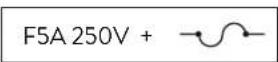
If you replace the fuse for DC power Cord, use F 5A 250V type. The parameters and the symbol of the fuse are indicated in the following label.
HOW TO OPERATE WITH YOUR TRANSCEIVER
- Screw the microphone plug into the microphone jack.
- Make sure your antenna is securely connected to the antenna connector.
- Make sure the SQUELCH control is turned fully counterclockwise.
- Turn on the unit and adjust the volume control.
- Select your desired channel.
- To transmit, press the PTT button and speak in a normal tone of voice.
- To receive, release the PTT button.
SQUELCH
The squelch function cuts out annoying background noise when no signal is being received. To do this, set the channel selector to a channel where no signals are present or wait until signals cease on your channel.
Midland M-10 is supplied with two types of squelch: manual and automatic.
Manual: rotate the squelch knob in a counter-clockwise direction and stop before you hear a 'clip', then rotate it clockwise to the point where the background noise just stops. Do not set the squelch too high, otherwise weak signals will not be able to open the squelch circuit.
Automatic: rotate completely the squelch knob counter-clockwise and stop after you will hear a 'click'. Now the squelch will be automatically adjusted according to the background noise.
REMOTE SPEAKER
A speaker rated at 3-10 watts should be used for this function. Plug the speaker into the EXT jack on the rear of the transceiver. When the external speaker is plugged in, the internal one is disconnected.
The frequency bands must be chosen according to the country where you are going to operate.
Procedure:
- Turn off the radio
- Switch on the transceiver while keeping pressed the UP/DOWN buttons at the same time
- Push the UP/DOWN buttons and select the desired frequency band (see the chart here below)
- Press the PTT button on the microphone to confirm your selection
Note1: in the UK frequency band it is possible to select directly the EC or EN frequency bands by moving the AM/FM (EC/EN) selector.
Note2: if you select a frequency band operating in FM only, the AM/FM selector will be useless.
| Digits displayed | Country |
| EC 40CH FM 4W | |
| EU Europe | 40CH FM 4W / 40CH AM 1W |
| I2 Italy | 34CH AM/FM 4W |
| IT Italy | 40CH AM/FM 4W |
| PL Poland | 40CH AM/FM 4W |
| D3 Germany | 80CH FM 4W / 40CH AM 1W |
| D4 Germany | 80CH FM 4W / 40CH AM 4W |
| UK England | 40CH FM 4W UK frequencies + EC 40CH FM 4W |
| FOR EXTRA EU MARKET ONLY | |
| PX Poland | 400CH AM/FM 4W Polish frequencies |
| RU Russia | 400CH AM/FM 4W |
| PC Private | Channels 50CH AM/FM |
TECHNICAL SPECIFICATIONS
GENERAL
| Channels | (see the frequency band chart) |
| Frequency Range* | 26.565-27.99125 MHz |
| Duty cycle (% or 1 hour) | TX 5% RX 5% Stand by 90% |
| Frequency Control | PLL |
| Operating Temperature Range | 10^/+55^ |
| DC input voltage | 12.6V DC ± 10% |
| Size | 122x35x195mm |
| Weight | 820 g |
RECEIVER
| Receiving system | dual conversion superheterodyne |
| Intermediate frequency | ^10 IF: 10.695 MHz - ^11 IF: 455 KHz |
| Sensitivity | ≤1μV for 20 dB SINAD |
| Audio output power @10% THD | 4W @ 8 Ohm |
| Audio distortion | less than 8% @ 1 KHz |
| Image rejection | 65 dB |
| Adjacent channel rejection | 65 dB |
| Signal/Noise ratio | 45 dB |
| Current drain at stand/by | < 250mA |
TRANSMITTER
| Output power | 4W max |
| Modulation | FM: 1,8 KHz + 0,2 KHzAM: ≥90% |
| Frequency response | 300 Hz/3 KHz |
| Output impedance | RF 50 Ohm unbalanced |
| Signal/Noise Ratio | 40 dB MIN |
| Current drain | 1100mA |
* covering a1 approved LU frequency bands
Specifications are subject to change without notice.
A readily accessible disconnect device shall be incorporated in the installation wiring.
The disconnect device shall disconnect both poles simultaneously.
INHALT
BEDIENUNGSELEMENTE 2
FRONTBLENDE 2
RÜCKWAND 4
MIKROFON 4
INSTALLATION 5
STROMVERSORGUNG 5
INSTALLATION EINER ANTENNE 5
Italy - Restrictions on the use - According to the Italian Frequency Allocation Table, issued on the G.U. No. 169 - Supplement 146 - of 20th July 2002 - note 49G, the standard in AM modulation needs a radiating system with a gain not higher than -6dB, such as, for example, with the antenna "PC8" with original cable.
Heraby Cte International Srl declares that this product is in compliance with the essential requirements and other relevant provisions of Directive 1999/5/EC. The declaration of conformity is available on the web site www.midlandeurope.com
A/D/CH/FL
Produced or imported by:
CTE INTERNATIONAL s.r.l.
Via. R.Sevardi 7 - 42124 Mancasale Reggio Emilia Italy
Imported by: ALAN-NEVADA UK
Unit 1 Fitzherbert Spur Farlington Portsmouth
Hants. P061TT - United Kingdom
www.nevada.co.uk
The use of this transceiver can be subject to national restrictions. Read the instructions carefully before installation and use.
Importado por:
ALAN COMMUNICATIONS, S.A.
C/Cobalt, 48 - 08940 Cornellá de Llobregat
MIDLAND®
PUT YOURSELF IN ACTION

- Display with backlight
- REAR PANEL
- MICROPHONE
- INSTALLATION
- POWER SUPPLY
- INSTALLING AN ANTENNA
- REPLACING FUSE
- HOW TO OPERATE WITH YOUR TRANSCEIVER
- SQUELCH
- REMOTE SPEAKER
- Procedure:
- TECHNICAL SPECIFICATIONS
- INHALT
- BEDIENUNGSELEMENTE 2
- A/D/CH/FL
- CTE INTERNATIONAL s.r.l.
- Imported by: ALAN-NEVADA UK
- www.nevada.co.uk
- ALAN COMMUNICATIONS, S.A.
Brand : MIDLAND
Model : M-10
Category : Talkie Walkie