9320 - Access Control Dormakaba - Free user manual and instructions
Find the device manual for free 9320 Dormakaba in PDF.


| Product Type | Door Closer |
| Model | 9320 |
| Brand | Dormakaba |
| Dimensions (mm) | 255 x 45 x 60 |
| Weight (kg) | 1.5 |
| Material | Aluminum alloy body, steel arm |
| Mounting Type | Surface mounted (standard arm) |
| Door Width Range | Up to 1100 mm |
| Door Weight Range | Up to 80 kg |
| Spring Size | EN 2-4 adjustable |
| Closing Speed Adjustment | Adjustable via valves (closing and latch speed) |
| Backcheck | Adjustable backcheck from 70° to 120° |
| Latch Action | Adjustable hydraulic latch speed |
| Temperature Range | -20°C to +40°C |
| Compliance | EN 1154 (grade 2) |
| Fire Resistance | Suitable for fire doors (depends on door assembly) |
| Finish Options | Silver, white (other colors on request) |
| Warranty | 2 years from date of purchase |
| Included Components | Closer body, arm assembly, mounting screws, template |
| Installation Position | Push or pull side (universal) |
| Maintenance | Periodic check of screws and oil leakage; clean with damp cloth |
| Spare Parts Available | Arm set, closer body, covers |
Frequently Asked Questions - 9320 Dormakaba
User questions about 9320 Dormakaba
0 question about this device. Answer the ones you know or ask your own.
Ask a new question about this device
Download the instructions for your Access Control in PDF format for free! Find your manual 9320 - Dormakaba and take your electronic device back in hand. On this page are published all the documents necessary for the use of your device. 9320 by Dormakaba.
USER MANUAL 9320 Dormakaba
Where to install proximity readers
Low to high traffic doors
Interior or exterior doors
Narrow door frames
Inside walls
Architecturally sensitive installations
A black cover is provided with the proximity reader.
A gray Slimline cover is available as 9320/21CAPG.
A white Micro cover is available as 9322/23CAPW.
Where NOT to install proximity readers
Behind metal – RF will not penetrate
On a ferrous metal surface – diminishes read range
Near TVs or monitors – RF will interfere with reader
Note: READER IS WEATHER RESISTANT. Do not apply sealant or gaskets to the rear of the reader, as this may cause condensation to build up and adversely affect reader operation.
Mounting Instructions
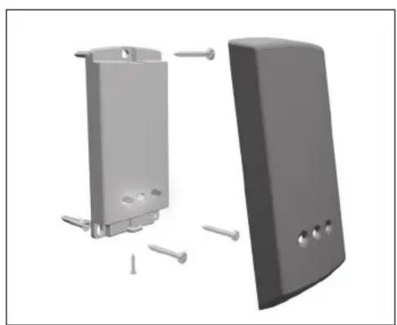
RCI 9320 Slimline Reader
- Select appropriate space on wall for reader installation. Ensure that there are no hidden electrical hazards prior to drilling.
- Drill hole for reader wiring to pass through.
- Remove changeable cover from reader if necessary. Cover is removed by prying off from the bottom of cover only.
- Pass the readers 6 wires through hole.
- Hold reader against wall with LED's at bottom, mark position of three mounting holes.
- Drill the three mounting holes as appropriate for the type of fasteners being used.
- Install / level the reader and secure with three mounting screws.
- Install removable cover by engaging top tab and pivoting cover down over reader. Cover should snap in place when installed properly.
- Cover is secured with single screw (provided) on lower edge of cover. Important: Cover screw must not be longer than 1/4" or internal damage will result, voiding warranty.
Fig. 1
natural_image
3D rendering of two electronic device components with screws and mounting holes, shown from different angles (no text or symbols)RCI 9322 Micro Reader
- Select appropriate space on wall for reader installation. Ensure that there are no hidden electrical hazards prior to drilling.
- Holding reader back plate against wall, mark position for two screw holes and center hole for reader.
- Drill center hole 13/16" (7/8" max) in diameter. If wall is not hollow, ensure depth of the hole is at least 2-3/4" deep to prevent damaging reader/wiring.
- Drill two smaller mounting holes as appropriate for type of fastener being used.
- If necessary, drill hole through wall for wiring to pass through.
- Screw back plate onto reader until flush with front of reader.
- Pass reader wires through hole and out other side as appropriate.
- Insert reader into hole being careful not to damage wiring. Secure back plate with two screws provided.
- Snap the appropriate colored cap over the back plate by engaging one side and press the other side until it snaps securely in place.
Fig. 2
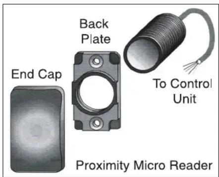
Fig. 3

Micro Reader surface mounted onto wall using back plate. The plastic end cap is placed over the exposed end of the reader.
Fig. 4

Micro Reader surface mounted onto a hollow wall using the back plate. The plastic end cap is placed over the base plate.
Electrical Installation Instructions
- If installing using the Slimline Reader, reference Fig. 5. If installing using the Micro Reader, reference Fig. 6.
Black Wire Negative Power Input
Red Wire 12VDC Positive Power Input
Note: Unit requires a filtered and regulated power source for proper operation.
Green & Yellow Wires Lock Release Output. If electric locks are polarity conscious the yellow wire is positive.
Blue & Purple Wires Request to exit or remote release switch (normally open) momentary button may be connected for lock release to exit.
Switching Current 500mA continuous, 750mA for up to 7 seconds.
- Make electrical connections as per schematic below, removing clear plug-in connector on end.
Fig. 5

Fig. 6

Note: All installations must conform to local fire, National Building, and Life Safety Codes.
Programming Instructions for 9320/22
The reader operates with a Wallet of cards which contains:
an Enrolment Card, Fail Open Release Card, Silent Operation Card, Door Open Card, 10 Deletion Cards and 10 User Tokens (Cards or Fobs).
These card packs are sold separately and come in a variety of styles and colors.
Initializing the Reader
- When reader is powered for the first time, it must be initialized.
- Until initialized, the LED's (RCI 9320 only) will be flashing on and off. The sounder (RCI 9322 only) will beep 3 times per second.
- Take Enrolment Card you wish to enroll from Wallet.
- Present the Enrolment Card to reader(s).
- The LED's (RCI 9320 only) stops flashing. The (RCI 9322 only) stops beeping.
- All cards in Wallet are now valid; as such Wallet with programming cards and user cards must be stored in secure location to maintain proper building security.
Issuing Tokens
- On each page of Wallet, there are 2 'pairs' of opposing cards. A 'User Card' and a corresponding 'Deletion Card'. Do not mix up these pairs.
- Write users name on the Deletion Card.
- Take corresponding User Card from opposing pouch & issue to user.
Deleting a User (Barring)
- When token (card or fob) become lost or stolen, it is important to delete missing token from your system to avoid unauthorized access.
- To delete user, take their corresponding Deletion Card from Wallet.
- Present Deletion Card to reader(s). This will remove lost token (card or fob) from accessing your building.
- Should deleted user token (card or fob) become found, system administrator can re-enroll token. See "To Re-Enroll a Deleted User" below.
To Re-Enroll a Deleted User
- System administrator can re-validate token (card or fob).
- Present Enrolment Card to reader(s).
- Present users deleted token (card or fob) to reader(s).
- Users token (card or fob) will now be valid again.
Setting "Door Open" Time
- Take Door Open Time function card from the Wallet.
- Present card to reader(s). Reader will begin beeping once per second.
- Wait for desired period of time you wish door to remain unlocked.
- Present Door Open function card again at end of that period to set unlock time. Beeping will stop.
Fail Open Release Card
Note: This card should only be used with a Fail Unlocked lock.
1. proximity compact systems are configured for Fail Locked by default.
2. Take Fail Open Release function card from wallet pack.
3. Present card to reader(s). Reader will beep.
4. Reader is now set to Fail Unlocked mode. This allows safe operation of the door in case of fire: The lock will release when power is cut.
5. To revert back to Fail Locked mode, present card again.
Silent Operation Card
- Take Silent Operation function card from Wallet.
- Present card to reader(s). Reader will beep.
- Reader is now in silent operation mode.
- Present card again to disable silent operation mode. Reader will beep
To Enroll another Card Pack
- Additional Card Pack(s) may be added as needed.
- To enroll an additional Card Pack, first present the Enrolment Card from any currently enrolled Card Pack to reader.
- Follow this by presenting the Enrolment Card from the new Card Pack.
- New Card Pack is now enrolled
Two Factory Reset Methods Available
Note: Performing factory reset will ERASE all currently enrolled tokens from reader. A factory reset should only be done as a last resort after all other troubleshooting attempts were unsuccessful. Factory defaults: Door Open time = 7 seconds, Fail Open Release = Fail Locked, No tokens valid and Sounder = On.
Card Reset Instructions
- Present Enrolment Card.
- Present Door Open Time function card.
- Present Door Open Time function card again.
- Present Enrolment Card.
- Present Door Open Time function card.
- Present Door Open Time function card again.
- After a short delay, reader will reset back to factory default. Briefly remove power to complete the reset process.
Power-On Reset Instructions
- Remove power from the reader.
- If an exit button is connected, press and hold (If not, short blue & mauve wires together).
- Apply power to the reader and ignore initial two fast beeps.
- Wait for single beep, release (un-short) and press exit button (short) two additional times within 3 seconds.
- After a short delay, reader will reset back to factory default. Briefly remove power to complete the reset process.
Troubleshooting
| Problem Solution | |
| Door Open Time (DOT) card not accepted by reader | - Present the enrollment card to the reader- Present the DOT card to the reader- DOT card should now be accepted |
| Tokens (cards or fobs) not being accepted by the reader | - Present the enrollment card to the reader- Present the token to the reader- Tokens should now be accepted |
| Second Wallet (enrollment card) not being accepted by the reader | Additional Wallets can only be added to the reader by first presenting any one of the currently enrolled enrollment card(s) followed by the new Wallet enrollment card(s) |
- Where to install proximity readers
- Where NOT to install proximity readers
- Mounting Instructions
- RCI 9320 Slimline Reader
- RCI 9322 Micro Reader
- Electrical Installation Instructions
- Programming Instructions for 9320/22
- Initializing the Reader
- Issuing Tokens
- Deleting a User (Barring)
- To Re-Enroll a Deleted User
- Setting "Door Open" Time
- Fail Open Release Card
- Silent Operation Card
- To Enroll another Card Pack
- Two Factory Reset Methods Available
- Card Reset Instructions
- Power-On Reset Instructions
Brand : Dormakaba
Model : 9320
Category : Access Control