PT260 - Planer Cotech - Free user manual and instructions
Find the device manual for free PT260 Cotech in PDF.


| Product Type | Planer |
| Brand | Cotech |
| Model | PT260 |
| Dimensions (L x W x H) | 30 x 20 x 15 cm |
| Weight | 4.5 kg |
| Power Input | 1200 W |
| Voltage | 230 V ~ 50 Hz |
| No-Load Speed | 16,000 rpm |
| Planing Width | 82 mm |
| Planing Depth | 0 - 2 mm |
| Rabbeting Depth | 0 - 12 mm |
| Dust Bag Capacity | 2 L |
| Cable Length | 2 m |
| Noise Level (Lpa) | 90 dB(A) |
| Vibration Level (ah) | 5 m/s² |
| Functions | Planing, rabbeting, chamfering |
| Safety Features | Double insulation, lock-off switch, blade guard |
| Maintenance | Replace blades, clean dust port, lubricate bearings |
| Spare Parts Available | Blades, drive belts, carbon brushes |
| Warranty | 2 years |
Frequently Asked Questions - PT260 Cotech
Use the rabbeting edge guide for accurate results.
User questions about PT260 Cotech
0 question about this device. Answer the ones you know or ask your own.
Ask a new question about this device
Download the instructions for your Planer in PDF format for free! Find your manual PT260 - Cotech and take your electronic device back in hand. On this page are published all the documents necessary for the use of your device. PT260 by Cotech.
USER MANUAL PT260 Cotech
Important information:
Read the instruction manual carefully and make sure that you understand everything before you use the product, save it for future use.
Viktig information:
natural_image
Industrial machine with mounted components and wheels, no visible text or symbolsEnglish 2
Svenska 11
Norsk 20
Suomi 29
Ver. 200801
English
Planer & Thicknesser, article number: 30-7803, model: PT260
Please read the entire instruction manual before using and save it for future use. We apologise for any text or photo errors and any changes of technical data. If you have any questions concerning technical problems please contact our Customer Service Department (see address on reverse.)
Safety
Warning! When using this tool fundamental safety measures must be observed to decrease the risk of fire, electric shock and personal injury. Read all of these instructions before using the product and retain these instructions.
1. Keep the work place clean.
Cluttered areas and work tables are accidents waiting to happen.
2. Take the working environment into consideration.
Do not expose the tools to rain. Do not use the tools in damp or wet spaces. Keep the working area well-lit. Do not use the tools in the proximity of inflammable liquids or gases.
3. Avoid electric shocks.
Avoid physical contact with earthed objects such as water pipes, radiators, kitchen cookers and fridges.
4. Keep everyone at a distance.
Do not let anyone, especially children, who is not participating in the work touch the tool or any of the extensions. Keep everyone at a distance from the work place.
5. Store the tool in a safe space.
When the tool is not being used, store it in a dry, locked space out of the reach of children.
6. Do not force the tool.
It carries out the job more efficiently and safely at the intended feed speed.
7. Use the correct tool.
Do not force small tools to do big jobs which require powerful tools. Do not force a tool or auxiliary equipment to carry out work for which it is not designed; e.g. do not use a circular saw to cut down branches or timber.
8. Wear appropriate clothing.
Do not wear any loose clothing or jewellery as they can get caught in rotating parts. When working outdoors, non-slip shoes are recommended. Wear a hairnet (or similar) if you have long hair.
9. Always wear protective equipment.
Wear safety goggles. Use a protective mask if the work creates a lot of dust.
10. Use dust collecting equipment.
If it is possible to attach a dust collector to the tool, ensure that it is fitted and used properly.
11. Do not manhandle the power cable.
Instead of tugging at the cable, disconnect it by pulling the plug out of the socket. Ensure that the power cable does not come into contact with heat, oil or sharp edges.
12. Secure the workpiece properly.
When possible, use clamps or a vice to secure the workpiece. That is safer than holding the workpiece with one hand.
13. Do not overreach.
Ensure that you stand safely and with good balance at all times.
14. Keep the tools in working order.
Ensure that they are clean and that the cutting edges are sharp for an optimal and safe result. Follow the recommendations in the manual regarding lubrication and change of fittings. Check the power cable regularly. If it is damaged it should be changed by a qualified service technician. Check all extension cables regularly to ensure that they are not damaged. Ensure that the handles and controls of the machinery/tools are dry, clean and completely free from oil, grease etc.
15. Switch the power off.
Pull out the plug and press the emergency stop button before servicing and when changing fittings such as planer tools, drill bits, tools, abrasive belts or blades.
English
16. Remove all keys and service tools.
Make a habit of checking that all keys and service tools are removed from the machinery before switching on the power.
17. Avoid starting unintentionally.
Do not carry a tool with your finger on the switch/trigger if the cable is plugged into a socket. Ensure that the switch is in the off position when connecting the plug.
18. Use the correct extension cables.
When using extension cables outdoors, only use those which are intended for outdoor use. Use extension cables with sufficient conductivity. Uncoil the entire cable.
19. Use common sense and be careful.
Think twice before carrying out a working operation so that you can carry it out in a safe manner. Do not use the machinery/tool when you are tired, under the influence of medication etc.
20. Before starting the machinery check:
- That all covers and other parts are undamaged and in working order.
- That all moving parts can rotate freely and are correctly set.
- That no moving parts can jam.
- That no defects have arisen.
- Other circumstances which could influence the manner in which the work is carried out.
A safety guard or other part that has been damaged must be repaired by a service technician or changed.
Damaged power cables and switches must always be changed by a qualified technician. Never use the tool if you cannot switch it off or start it in a safe manner.
21. Use recommended fittings.
Using fittings that have not been recommended may cause accidents and personal injury.
22. Must be repaired by a qualified technician.
The machinery conforms to current safety requirements. Repairs on the machinery must always be carried out by a qualified technician using genuine replacement parts. Otherwise the tool may cause accidents or personal injury.
Specific safety instructions for the planer & thicknesser
- Never use the machine unless the protective covers are undamaged, correctly installed, and adjusted.
- Never use dull plane irons as this will increase the risk of kickback.
- When surface planing, the unused part of the cutter must be covered by the cutter guard.
- When surface planing short workpieces, a push stick should be used.
- The surface plane should not be used when planing grooves, sinks, tenons, or profiles.
- The operation of the anti-kickback mechanism and the feed rollers should be checked regularly to assure safe operation.
- Whether surface planing or thickening, a dust extractor should be attached to the plane.
Product labelling

Read the entire operations manual.

Always use protective goggles or a visor and a dust mask.

Always use ear protection.
English
2. Assembly
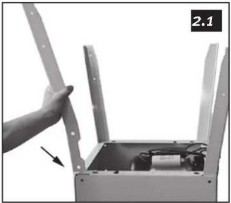
2.1 Attach the legs to the body secure them with hexagon bolt M8 x 16, spring washer B8, and hexagon nut M8.
2.2 Attach the rubber pads to the legs.
2.3 Attach the dust extractor by using the four plate screws (included).
2.4 Detach the fastening splints for the feed table for thickness planing, assemble the table, and secure it with the splints.
2.5 Add the output table and attach it with the two locking arms.
natural_image
Hand holding a metal frame with an open box containing electrical components and wiring (no visible text or symbols)
natural_image
Close-up of a hand operating a mechanical device with a tool, no visible text or symbols
natural_image
Close-up of a mechanical device with rollers and a sheet of paper, no visible text or symbols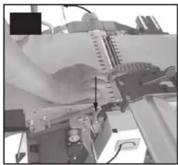
natural_image
Close-up of a mechanical device with no visible text or symbols2.6 Attach the fence attachment to the feed table with 2 M8 hexagon screws.
Pull the lever outwards to allow it to swing right or left.

natural_image
Simple line drawing of a mechanical lever or fulcrum with directional arrows indicating force or motion (no text or symbols)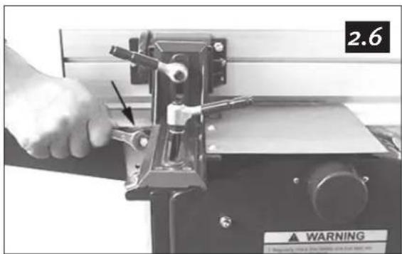
natural_image
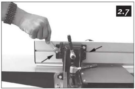
Close-up of a hand operating a mechanical device with a wrench and lever, labeled 'WARNING' (no readable text beyond label)2.7 Push the screw heads into the groove of the fence and attach it to the segment with the two self-locking nuts M6. Then attach the cover plate to the fence attachment with 2 M4x8 screws with cylinder heads and washers.

natural_image
Close-up of a hand using a tool to adjust or install a mechanical component, with arrows indicating direction (no visible text or symbols)
natural_image
Close-up of a hand using a tool to adjust or install a mechanical component, with no visible text or symbols.English
2.8 Disassemble the two upper dome nuts and washers. Attach the locking bolt of the power switch to the screws. Attach the washers and tighten the dome nuts.

natural_image
Close-up of a hand using a wrench to adjust or install a mechanical component (no visible text or symbols)
natural_image
Close-up of a mechanical device with a hand holding a wrench, showing no visible text or symbols.3. Adjustment of the fence
Turn the setscrews of the fence in and out as needed to achieve the exact segment stop of 45^ and 90^ .
Note: Lubricate all sliding areas.

natural_image
Close-up of a hand using a tool to adjust or install a mechanical component (no visible text or symbols)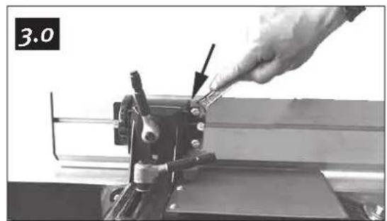
natural_image
Close-up of a hand using a tool to adjust or install a mechanical component, no visible text or symbols4. Electrical connection
- Double-check that the voltage agrees with that indicated on the label on the motor rating plate.
- Connect the machine to an earthed wall socket through an earthed extension cord.
5. Power switch
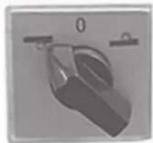
All power switches have zero voltage tripping to prevent the plane from starting after a power outage.
Please note:
• There are two power switches on the panel.
- The one on the right is the main switch with zero voltage tripping.
- The one on the left is the program lever to change between surface and thickness planning.
- For your safety, always set the lever to "0" when the machine is not in use.
5.1
natural_image
Close-up of a hand holding a small object with a handle, no visible text or symbols
natural_image
Close-up of a metallic mechanical component with square cutouts and mounting holes (no text or symbols visible)English
6. Dust extraction
The package includes a sleeve coupling connectable to a diameter of 100 mm. Always use some form of dust extraction when planing.
7. Surface planing
The following measures must be taken before level planing.
7.1 Set the program lever to surface planing ○.
7.2 Set the thickness planer table to approximately 2/3 of its full capacity and attach the dust hood. Raise the table and lock the hood. Make sure that the socket on top of the dust hood locks against the spindle above.
NOTE: Unless the dust hood is installed, the safety switch will not work and the machine will not start.
7.3 Make sure that the surface planer table, which can be disassembled, is locked so that the safety breaker is free to operate.
NOTE: Unless the locking arms are in the right position, the plane will not start.
If the machine still does not start, please contact our Customer Service Department.
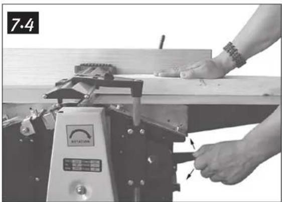
7.4 Adjust the height with the lever to the left of the plane. After lifting the locking lever, you can adjust the cutterguard sideways to the correct gap for the workpiece when surface planing. Lower the locking lever to lock the cutterguard in position. Push the workpiece against the feed table and set the cutter guard to the height of your left hand. (The workpiece should barely fit through the gap.) Start the motor and slowly and steadily feed the workpiece across the cutter. Let your hands glide across the cutter guard.
natural_image
Close-up of hands operating a wooden machine with a rotary switch (no visible text or symbols)7.5 When level planing edges, start by loosening the locking lever to the cutter guard and setting the gap to the width of the workpiece. The springing plastic piece at the right edge of the guard should be lightly pressed to the workpiece. Lock the guard in position and start the motor.
Feed the workpiece slowly and steadily across the cutter. Make sure the fence is at a 90° angle exactly (or other angle desired) to the output table and push the workpiece to the fence and downward during feeding.

natural_image
Exterior view of a white electronic device with two switches and a circular button (no visible text or symbols)
natural_image
Close-up of a pipe assembly with bolts and a mechanical clamp (no visible text or symbols)
natural_image
Close-up of a gloved hand holding a mechanical device with a magnified inset showing a small mechanical component (no visible text or symbols)
natural_image
Close-up of hands using a mechanical testing machine with a scale and measurement device (no visible text or symbols)
natural_image
Close-up of a hand operating a wooden machine with a gear mechanism, no visible text or symbolsEnglish
8. Thickness planing
The following measures should be taken before thickness planing.
8.1 Set the program lever to thickness planing
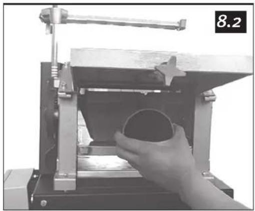
8.2 Wind the surface planer height adjustment crack handle anticlockwise and remove the dust hood.
8.3 Fold out the locking arms for the surface planing table and remove the table. Pull the cutter cover outside the table and set it to its top position.
8.4 Turn in the output hood across the cutter and attach the dust hood. Lock it with the cutter cover. The dust hood acts as a cutter cover when thickness planing.
NOTE: Never operate the machine unless the dust hood is installed and locked.
A circuit breaker prevents start with an improperly installed dust hood.

natural_image
Mechanical assembly with gears and a highlighted mechanical component (no visible text or symbols)8.5 Change the setting of the machine to thickness planing as described above. Set the thickness planing table to the desired thickness of the workpiece.
Maximum cutting thickness: 3 mm. (NOTE: Measure at both ends of the workpiece.)
Start the machine and feed in the workpiece with the planed surface facing downwards and push slowly until the feed rolls grip. If the workpiece is wedge-shaped, feed in the thickest end first.
natural_image
Close-up of a hand holding a circular object inside a mechanical press or clamp device (no visible text or symbols)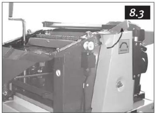
natural_image
Industrial machine component with visible wiring and control panel (no text or symbols)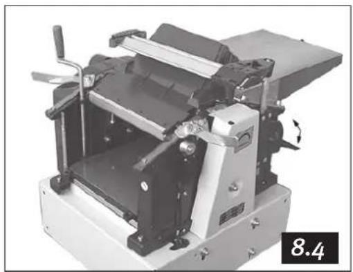
natural_image
Mechanical machine component with rotating arm and mounting base (no visible text or symbols)
natural_image
Mechanical machine component with no visible text or symbols, labeled '8.4' in corner (no readable text or symbols on the machine itself)English
9. Replacing/adjusting disposable cutter irons
Note: Unplug the device before service.
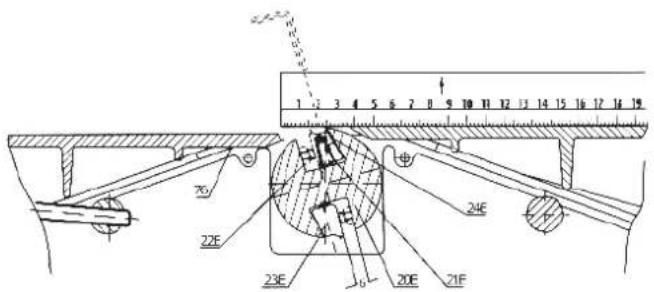
Remove the fence. Loosen the hexagon screws on the locking wedge (pushing the cutter iron against the cutter) with the included 10 mm spanner by turning these clockwise inwards. Remove the cutter iron and the locking wedge from the groove of the cutter. Clean the wedge, groove, and cutter iron of debris, shavings, and dust with an oily cloth.
Turn the cutter iron or replace it. Reinstall the iron and wedge back in the groove and lock them in position by turning the screws anticlockwise (but turn only slightly so that they do not fall out.) Check how far the cutter iron protrudes above the output table by laying a ruler on the output table or by using a setting guage.
Maximum protrusion above the output table: 0.1 mm. Repeat with the other cutter iron.

natural_image
Close-up of hands using a cutting tool on a metal workbench, no visible text or symbols
natural_image
Close-up of a hand using a tool to cut or adjust a metal sheet, no visible text or symbolsAdjust the cutter protrusion using the included 3 mm allen key by turning the wedge's three setscrews in and out as desired. After achieving the correct setting, tighten the hexagon screws again. Start with the screw in the middle.
Note: Do not use a 10 mm spanner with a shaft longer than that which is included to avoid the risk of damaging the grooves. Immediately replace a locking wedge having with damaged grooves.

English
10. Drive belt tension
Check the drive belt tension after the first five machine hours. Remove the dome nut holding the belt cover (215) in place. Check the tension by pushing the belt as illustrated. It should be possible to push the belt about 15 – 20 mm.
11. Maintenance
Regularly clean the feed gears of the thicknessing plane with a brush or compressed air. Regularly lubricate all grease areas and chains with a few drops of motor oil. Make sure that no oil or other greasing agent comes in contact with the driving belt of the gears.
11.1 Regularly clean the thickening plane tables spindles and lubricate them with an oil spray, such as WD 40. Do not use regular motor oil.
11.2 Assure that the feed and output tables, plus the surface plane table, are free of resins. Clean them regularly, and then wax them with a suitable lubricant spray so that the workpieces will glide easily.

natural_image
Close-up of a mechanical device with hands operating it, no visible text or symbols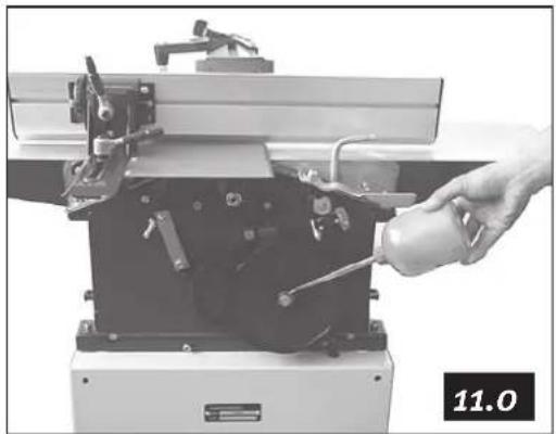
natural_image
Close-up of a hand operating a machine tool with tools and a bottle, no visible text or symbols
natural_image
Hand operating a mechanical device with a spray bottle, no visible text or symbols on the device itself12. Responsibility of the user
This machine functions according to the description in this operations manual if installed, used, maintained, and repaired in accordance with the instructions herein.
The machine must be checked regularly. Defective equipment (including connecting cables) must not be used.
Defective, missing, worn, deformed, or otherwise damaged parts must be replaced immediately.
If such repairs or replacements are necessary, we recommend the use of a qualified technician.
The machine, or the parts of the machine, should not be modified. The user of the machine has the sole responsibility for any faulty functions that may be caused by violations of the instructions for use, unauthorized modifications, faulty maintenance, damages, or faulty repairs.
13. Disposal

Follow local ordinances when disposing of this product. If you are unsure about how to dispose of this product contact your municipality.
English
14. Technical data
Table surface, surface plane: 260 x 1000 mm
Table surface, thickness plane: 250 x 400 mm
Max. planing width: 260 mm
Max. height, thickness planing: 155 mm
Max. chip size: 3 mm
Cutter diameter: 63 mm
Planing irons: 2 pairs
Cutter revolutions: 6500 RPM
Feed (surface plane): 5 m/min
Motor revolutions: 2800 RPM
Max. angle of the fence: 45^
Table height: 860 mm
Weight: 60 kg
Noise level: 75.7 dB (A) unloaded, 90.3 dB (A) loaded
Motor: 2.2 kW/3hp, 230V, 50Hz
Svenska
Rikt & planhyvel, artikelnummer 30-7803, model: PT260
natural_image
Hand holding a metal frame with an arrow pointing to the interior box, no visible text or symbols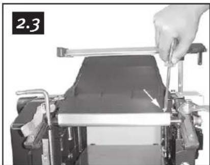
natural_image
Close-up of a hand operating a mechanical device with a tool, no visible text or symbols
natural_image
Close-up of a mechanical printer or scanner with roller rollers and mechanical components (no visible text or symbols)
natural_image
Close-up of a robotic arm with visible mechanical components and a hand adjusting the part (no text or symbols)natural_image
Simple line drawing of a mechanical component with directional arrows (no text or symbols)
natural_image
Close-up of a hand operating a mechanical device with a warning label (no readable text or symbols beyond the label)natural_image
Close-up of a hand using a tool to adjust or install a mechanical component, with arrows indicating direction (no text or symbols visible)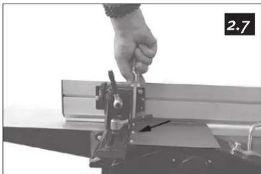
natural_image
Close-up of a hand operating a mechanical clamp or fixture with a black arrow pointing to a component (no visible text or symbols)Svenska
natural_image
Close-up of a hand using a wrench to adjust or install a mechanical component (no visible text or symbols)
natural_image
Close-up of a mechanical device with a hand holding a tool, no visible text or symbolsnatural_image
Close-up of a hand using a tool to adjust or install a mechanical component (no visible text or symbols)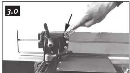
natural_image
Close-up of a hand using a tool to adjust or install a mechanical component, with no visible text or symbols.4. Elanslutning
natural_image
Two grayscale images showing a device with a handle and control panel, no visible text or symbols.Svenska
6. Spånsugning
natural_image
Close-up of a white electronic device with two switches and a circular button, no visible text or symbols.
natural_image
Close-up of a pipe assembly with metal fittings and a magnified inset showing a circular detail (no text or symbols visible)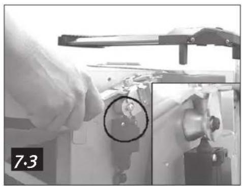
natural_image
Close-up of a gloved hand holding a mechanical device with a magnified inset showing a small component (no visible text or symbols)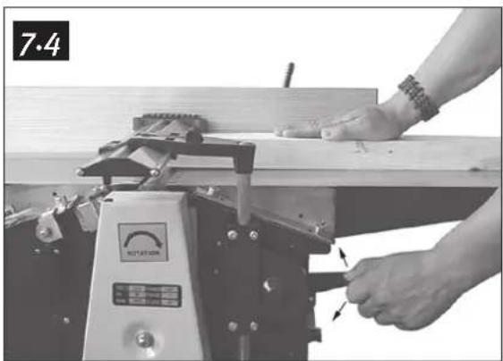
natural_image
Close-up of a hand using a machine tool to adjust or install a wooden plank, no visible text or symbols on the device or background.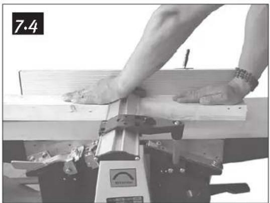
natural_image
Close-up of hands using a wooden plank on a machine, no visible text or symbolsnatural_image
Close-up of a hand operating a wooden machine with a gear mechanism, no visible text or symbolsSvenska
8. Planhyvling
natural_image
Close-up mechanical assembly showing gears and a close-up of a mechanical component (no visible text or symbols)natural_image
Close-up of a hand holding a circular object inside a mechanical clamp or frame (no visible text or symbols)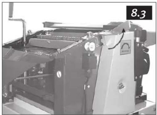
natural_image
Industrial machine component with visible internal structure and pipe fittings (no text or symbols)
natural_image
Mechanical machine with rotating components and a labeled section '8.4' (no readable text or symbols on the device itself)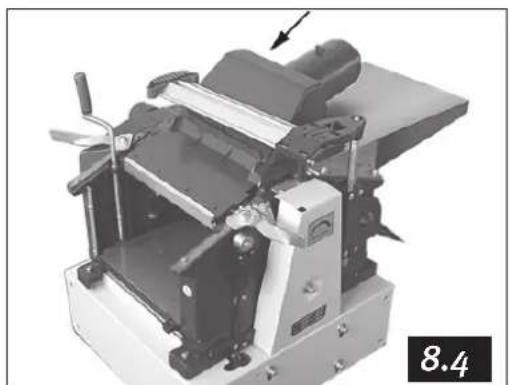
natural_image
Mechanical machine component with no visible text or symbols, labeled '8.4' in corner (no readable text or symbols on the machine itself)Svenska
natural_image
Close-up of hands operating a mechanical setup with a ruler and clamped components (no visible text or symbols)
natural_image
Close-up of hands operating a mechanical tool with a ruler and clamping bracket (no visible text or symbols)natural_image
Close-up of a mechanical device with hands operating it, no visible text or symbols11. Vård
natural_image
Close-up of a hand holding a bottle next to a machine component (no visible text or symbols)natural_image
Hand operating a mechanical device with a spray bottle, no visible text or symbols on the device itselfnatural_image
Hand holding a metal frame with an arrow pointing to the interior box, no visible text or symbols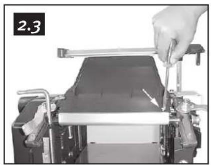
natural_image
Close-up of a hand using a tool to press or adjust a mechanical component, no visible text or symbols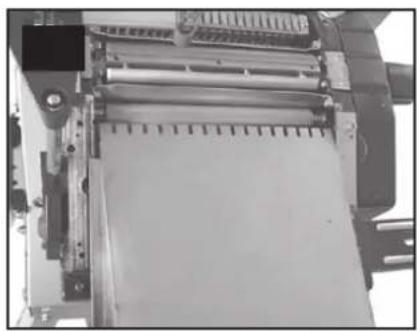
natural_image
Close-up of a mechanical device with rollers and a sheet of paper, no visible text or symbols
natural_image
Close-up of a robotic arm with visible mechanical components and a hand holding a tool (no text or symbols)2.6 Fest anholdsfestet i innmatingsbordet med 2 stk. M8 sekskantskruer.
natural_image
Simple line drawing of a mechanical lever or fulcrum with directional arrows indicating force or movement (no text or symbols)
natural_image
Close-up of a hand operating a mechanical device with a warning label (no readable text or symbols beyond the label)2.7 Skyv inn skruehodene i sporet på anholdet og fest det i segmentet med de to selvåsende mutrene M6. Fest deretter dekkplaten på anholdsfestet med 2 stk. M4x8 skruer med sylinderhode samt skiver.
natural_image
Close-up of a hand operating a mechanical clamp or fixture with arrows indicating movement (no text or symbols visible)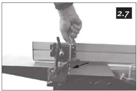
natural_image
Close-up of a hand operating a mechanical clamp or fixture with a metal frame (no visible text or symbols)Norsk
natural_image
Close-up of a hand using a wrench to adjust or install a mechanical component (no visible text or symbols)
natural_image
Close-up of a mechanical device with a hand adjusting a tool, no visible text or symbolsnatural_image
Close-up of a hand using a tool to cut or inspect a mechanical component (no visible text or symbols)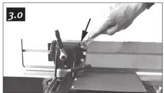
natural_image
Close-up of a hand using a tool to adjust or install a mechanical component (no visible text or symbols)4. Strømtilkobling
- Kontroller at nettspenningen stemmer overens med angitt merkespenning på motorens merkeplate.
- Koble maskinen med en jordet skjøteledning til et jordet vegguttak.
5. Strømbryter
natural_image
Two grayscale images showing a device with a handle and control panel, no visible text or symbols.Norsk
6. Sponutsuging
natural_image
Close-up of a hand operating a machine tool with a gauge and pointer, no visible text or symbolsnatural_image
Close-up of a white electronic device with two control buttons and a hand icon, mounted on a stand (no visible text or symbols)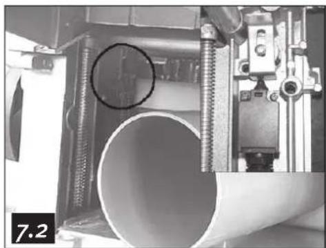
natural_image
Close-up of a pipe assembly with metal fittings and a circular hole, no visible text or symbols
natural_image
Close-up of a robotic arm with a magnified inset showing a small mechanical component (no visible text or symbols)
natural_image
Close-up of hands operating a wooden plank with a measuring instrument (no visible text or symbols)
natural_image
Close-up of a hand operating a wooden machine with a tool, no visible text or symbolsNorsk
8. Planhøvling
natural_image
Mechanical assembly with gears and a highlighted component (no visible text or symbols)natural_image
Close-up of a hand holding a circular object inside a mechanical clamp or frame (no visible text or symbols)
natural_image
Industrial machine component with visible pipes and control panel (no text or symbols)
natural_image
Mechanical machine with rotating shaft and mounting base, no visible text or symbols
natural_image
Mechanical machine component with no visible text or symbols, labeled '8.4' in corner (no readable text or symbols on the machine itself)Norsk
natural_image
Close-up of hands operating a mechanical setup with a ruler and clamping device (no visible text or symbols)
natural_image
Close-up of hands operating a mechanical clamp or tool on a workbench, no visible text or symbolsnatural_image
Close-up of a mechanical device with hands operating it, showing internal components and a numbered label '10.0' (no readable text or symbols on the device itself)11. Vedlikehold
natural_image
Hand operating a machine with tools and a bottle, no visible text or symbols
natural_image
Person operating a mechanical device with a spray bottle, no visible text or symbols on the device itselfnatural_image
Close-up of a hand holding a wooden bracket with an inset showing a cylindrical component (no text or symbols visible)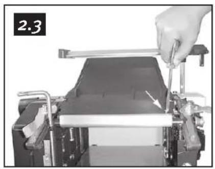
natural_image
Close-up of a hand using a tool to press or adjust a mechanical component, no visible text or symbols
natural_image
Close-up of a mechanical printer or scanner with roller and clamping mechanism (no visible text or symbols)
natural_image
Close-up of hands operating a mechanical device with a tool and a numbered label '2.5' (no readable text or symbols on the device itself)natural_image
Simple line drawing of a mechanical component with two arms and directional arrows (no text or symbols)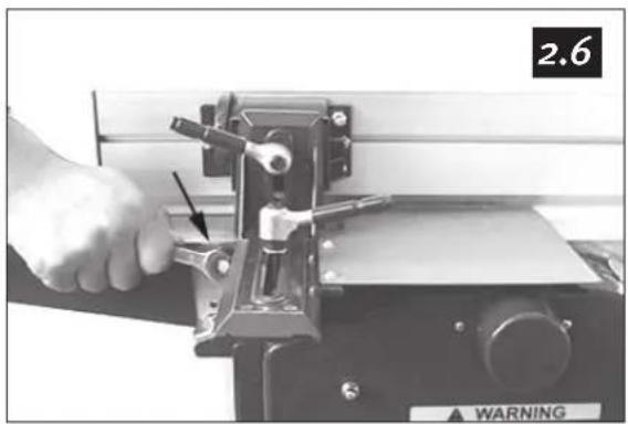
natural_image
Close-up of a hand operating a mechanical device with a warning label (no readable text or symbols beyond the label)natural_image
Close-up of a hand using a tool to adjust or install a mechanical component, with arrows indicating direction (no text or symbols visible)
natural_image
Close-up of a hand using a tool to adjust or install a mechanical component (no visible text or symbols)Suomi
natural_image
Close-up of a hand using a wrench to adjust or install a mechanical component (no visible text or symbols)
natural_image
Close-up of a mechanical device with a hand adjusting a switch, no visible text or symbols3. Tuen asennus
natural_image
Close-up of a hand using a tool to adjust or install a mechanical component (no visible text or symbols)
natural_image
Close-up of a hand using a tool to adjust or install a mechanical component, no visible text or symbols4. Sähköliitäntä
natural_image
Two grayscale industrial control switches with no visible text or symbols on the switches themselves.Suomi
6. Pölynpoisto
natural_image
Close-up of a white electrical switchgear box with two buttons and a small inset showing a device (no visible text or symbols)
natural_image
Close-up of a pipe assembly with coiled pipes and a circular hole, no visible text or symbols
natural_image
Close-up of a hand operating a mechanical device with a magnified inset showing a close-up of a component (no visible text or symbols)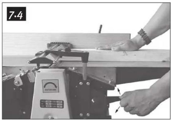
natural_image
Close-up of a hand using a machine tool on a wooden workbench, no visible text or symbolsnatural_image
Close-up of hands operating a wooden plank with a moving device (no visible text or symbols)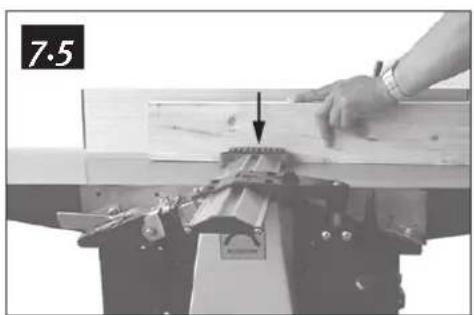
natural_image
Close-up of a hand using a tool to work on a wooden beam, with a mechanical clamp and bracket (no visible text or symbols)Suomi
8. Tasohöyläys
natural_image
Close-up of a hand operating a mechanical press or clamp device with a circular component, no visible text or symbols.
natural_image
Industrial machine with control panel and rotary dial (no visible text or symbols)
natural_image
Mechanical assembly with gears and a highlighted mechanical component (no visible text or symbols)
natural_image
Industrial machine with mechanical components and a labeled section '8.4' (no readable text or symbols on the device itself)natural_image
Mechanical machine component with no visible text or symbols, featuring a numbered label '8.4' at the bottom right corner.Suomi
natural_image
Close-up of hands using a tool to cut or adjust a metal sheet, no visible text or symbols
natural_image
Close-up of a hand using a tool to cut or adjust a metal sheet on a machine (no visible text or symbols)Suomi
10. Hihnan kireys
natural_image
Close-up of a mechanical device with hands operating it, no visible text or symbols
natural_image
Close-up of a hand holding a small cylindrical object next to a mechanical device (no visible text or symbols)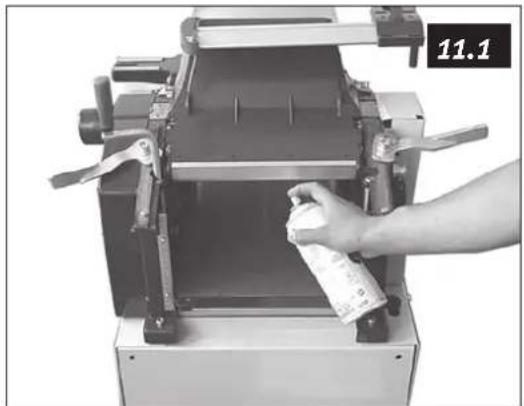
natural_image
Hand operating a mechanical device with a spray bottle, no visible text or symbols on the device itself.Declaration of Conformity

Hereby, Clas Ohlson AB declares that the machinery:
PLANER/THICKNESSER
CO/TECH 30-7803 / PT260
Complies with the provisions of the :
Machinery directive 98/37/EC
Complies with the model which has obtained an "EC" type certificate,
no. E 9931407E01 issued by the following notified body:
TÜV Rheinland Product Safety GmbH, Am Grauen Stein, 511 05 Köln, Germany
Complies with the provisions of the following harmonized standards:
EN 61029-1:1995
EN 61029-2-3:1997
Also complies with the provisions of following directives:
2006/95/EC LOW VOLTAGE EQUIPMENT
89/336/EEC EMC
Insjön, Sweden, January 2008
Klas Balkow
President
Clas Ohlson, 793 85 Insjön, Sweden
SVERIGE
KUNDTJÄNST Tel: 0247/445 00
Fax: 0247/445 09
E-post: kundtjanst@clasohlson.se
INTERNET www.clasohlson.se
BREV Clas Ohlson AB, 793 85 INSJÖN
NORGE
KUNDESENTER Tlf.: 23 21 40 00
Faks: 23 21 40 80
E-post: kundesenter@clasohlson.no
INTERNETT www.clasohlson.no
POST Clas Ohlson AS
Postboks 485 Sentrum, 0105 OSLO
SUOMI
ASIAKASPALVELU Puh: 020 111 2222
Faksi: 020 111 2221
For consumer contact, please visit
www.clasohlson.co.uk and click on
customer service.
INTERNET www.clasohlson.co.uk
CLAS OHLSON
- English
- Planer & Thicknesser, article number: 30-7803, model: PT260
- Safety
- Keep the work place clean.
- Take the working environment into consideration.
- Avoid electric shocks.
- Keep everyone at a distance.
- Store the tool in a safe space.
- Do not force the tool.
- Use the correct tool.
- Wear appropriate clothing.
- Always wear protective equipment.
- Use dust collecting equipment.
- Do not manhandle the power cable.
- Secure the workpiece properly.
- Do not overreach.
- Keep the tools in working order.
- Switch the power off.
- Remove all keys and service tools.
- Avoid starting unintentionally.
- Use the correct extension cables.
- Use common sense and be careful.
- Before starting the machinery check:
- Use recommended fittings.
- Must be repaired by a qualified technician.
- Specific safety instructions for the planer & thicknesser
- Product labelling
- Assembly
- Adjustment of the fence
- Electrical connection
- Power switch
- Please note:
- Dust extraction
- Surface planing
- Thickness planing
- Replacing/adjusting disposable cutter irons
- Note: Unplug the device before service.
- Drive belt tension
- Maintenance
- Responsibility of the user
- Disposal
- Technical data
- Svenska
- Rikt & planhyvel, artikelnummer 30-7803, model: PT260
- Elanslutning
- Spånsugning
- Planhyvling
- Vård
- Norsk
- Strømtilkobling
- Strømbryter
- Sponutsuging
- Planhøvling
- Vedlikehold
- Suomi
- Tuen asennus
- Sähköliitäntä
- Pölynpoisto
- Tasohöyläys
- Hihnan kireys
- Declaration of Conformity
- SVERIGE
- NORGE
Brand : Cotech
Model : PT260
Category : Planer