
HR1200 - Milling machine Cocraft - Free user manual and instructions
Find the device manual for free HR1200 Cocraft in PDF.


| Product Type | Milling machine (Router) |
| Brand | Cocraft |
| Model | HR1200 |
| Power Supply | 230 V AC, 50 Hz |
| Power Input | 1200 W |
| No-Load Speed | 11,000 - 30,000 rpm (variable) |
| Plunge Depth | 55 mm |
| Collet Chuck | 8 mm and 6 mm (included) |
| Weight | 2.7 kg |
| Sound Pressure Level (LpA) | 90 dB(A), K=3 dB(A) |
| Sound Power Level (LwA) | 101 dB(A), K=3 dB(A) |
| Vibration Value (ah) | 5.4 m/s², K=1.5 m/s² |
| Protection Class | II (Double insulation) |
| Main Functions | Plunge cutting, edge trimming, circle cutting, template routing |
| Depth Adjustment | 6-step depth stop with fine adjustment knob |
| Speed Control | Variable speed dial |
| Spindle Lock | Yes, for easy bit changes |
| Safety Features | Switch lock button, double insulation, dust extraction port |
| Accessories Included | Parallel guide, template guide, centering pin, dust extraction adaptor, 6 mm collet, spanner, Allen key |
| Maintenance | Clean with damp cloth; vacuum ventilation openings; store in dry place |
| Repair and Service | Only by qualified persons using original spare parts |
| Disposal | Recycle at local collection facility per EU WEEE directive |
Frequently Asked Questions - HR1200 Cocraft
User questions about HR1200 Cocraft
0 question about this device. Answer the ones you know or ask your own.
Ask a new question about this device
Download the instructions for your Milling machine in PDF format for free! Find your manual HR1200 - Cocraft and take your electronic device back in hand. On this page are published all the documents necessary for the use of your device. HR1200 by Cocraft.
USER MANUAL HR1200 Cocraft
FINE CUTTING DEPTH ADJUSTMENT
HANDÖVERFRÄS HÅNDOVERFRES KÄSIYLÄJYRSIN HANDOBERFRÄSE

Important!
Read the entire instruction manual carefully and make sure that you fully understand it before you use the equipment. Keep the manual for future reference.
Viktig information:
Original instructions
Bruksanvisning i original
Originalbruksanvisning
Please read the entire instruction manual before using the product and then save it for future reference. We reserve the right for any errors in text or images and any necessary changes made to technical data. In the event of technical problems or other queries, please contact our Customer Services (see address details on the back).
Safety
General Power Tool Safety Warnings
WARNING Read all safety warnings and all instructions. Failure to follow the warnings and instructions may result in electric shock, fire and/or serious injury.
Save all warnings and instructions for future reference.
The term "power tool" in the warnings refers to your mains-operated (corded) power tool or battery-operated (cordless) power tool.
1) Work area safety
a) Keep work area clean and well lit. Cluttered or dark areas invite accidents.
b) Do not operate power tools in explosive atmospheres, such as in the presence of flammable liquids, gases or dust. Power tools create sparks which may ignite the dust or fumes.
c) Keep children and bystanders away while operating a power tool. Distractions can cause you to lose control.
2) Electrical safety
a) Power tool plugs must match the outlet. Never modify the plug in any way. Do not use any adapter plugs with earthed (grounded) power tools.
Unmodified plugs and matching outlets will reduce risk of electric shock.
b) Avoid body contact with grounded surfaces, such as pipes, radiators, ranges and refrigerators. There is an increased risk of electric shock if your body is earthed or grounded.
c) Do not expose power tools to rain or wet conditions. Water entering a power tool will increase the risk of electric shock.
d) Do not abuse the cord. Never use the cord for carrying, pulling or unplugging the power tool. Keep cord away from heat, oil, sharp edges or moving parts.
Damaged or entangled cords increase the risk of electric shock.
e) When operating a power tool outdoors, use an extension cord suitable for outdoor use. Use of a cord suitable for outdoor use reduces the risk of electric shock.
f) If operating a power tool in a damp location is unavoidable, use a residual current device (RCD) protected supply. Use of an RCD reduces the risk of electric shock.
3) Personal safety
a) Stay alert, watch what you are doing and use common sense when operating a power tool. Do not use a power tool while you are tired or under the influence of drugs, alcohol or medication. A moment of inattention while operating power tools may result in serious personal injury.
b) Use personal protective equipment. Always wear eye protection. Protective equipment such as dust mask, non-skid safety shoes, hard hat, or hearing protection used for appropriate conditions will reduce personal injuries.
c) Prevent unintentional starting. Ensure the switch is in the off-position before connecting to power source and/or battery pack, picking up or carrying the tool. Carrying power tools with your finger on the switch or energising power tools that have the switch on invites accidents.
d) Remove any adjusting key or wrench before turning the power tool on.
A wrench or a key left attached to a rotating part of the power tool may result in personal injury.
e) Do not overreach. Keep proper footing and balance at all times. This enables better control of the power tool in unexpected situations.
f) Dress properly. Do not wear loose clothing or jewellery. Keep your hair, clothing and gloves away from moving parts. Loose clothes, jewellery or long hair can be caught in moving parts.
g) If devices are provided for the connection of dust extraction and collection facilities, ensure these are connected and properly used. Use of dust collection can reduce dust-related hazards.
4) Power tool use and care
a) Do not force the power tool. Use the correct power tool for your application. The correct power tool will do the job better and safer at the rate for which it was designed.
b) Do not use the power tool if the switch does not turn it on and off. Any power tool that cannot be controlled with the switch is dangerous and must be repaired.
c) Disconnect the plug from the power source and/or the battery pack from the power tool before making any adjustments, changing accessories, or storing power tools. Such preventive safety measures reduce the risk of starting the power tool accidentally.
d) Store idle power tools out of the reach of children and do not allow persons unfamiliar with the power tool or these instructions to operate the power tool. Power tools are dangerous in the hands of untrained users.
e) Maintain power tools. Check for misalignment or binding of moving parts, breakage of parts and any other condition that may affect the power tool's operation. If damaged, have the power tool repaired before use.
Many accidents are caused by poorly maintained power tools.
f) Keep cutting tools sharp and clean. Properly maintained cutting tools with sharp cutting edges are less likely to bind and are easier to control.
g) Use the power tool, accessories and tool bits etc. in accordance with these instructions, taking into account the working conditions and the work to be performed. Use of the power tool for operations different from those intended could result in a hazardous situation.
5) Service
a) Repairs and service should only be performed by qualified persons, and only with original spare parts. This guarantees the safety of the electrical hand tool.
Additional safety instructions for routers and trimmers
- Hold power tool by insulated gripping surfaces, because the cutter may contact its own cord. Cutting a "live" wire may make exposed metal parts of the power tool "live" and shock the operator.
- Use clamps or another practical way to secure and support the workpiece to a stable platform. Holding the work by your hand or against the body leaves it unstable and may lead to loss of control.
- Warning! Milling can result in the formation of dusts hazardous to health (e.g. arising from materials with paints containing lead, materials containing asbestos or some wood types), which can pose a risk to the operator or persons nearby. Make sure that the workplace is well ventilated. Always wear safety goggles, safety gloves and respiratory protection. Attach a dust extraction system.
- The permissible rotation speed of the attachment tools must be at least as high as the highest rotation speed indicated on the power tool. Accessories that run faster than the permissible speed can be destroyed.
- Cutters and other accessories must be exactly matching the tool holder (collet chuck) of your power tool. Attachment tools that are not exactly matching the tool holder of the power tool rotate unevenly, vibrate very strongly and can ultimately lead to a loss of control.
- Ensure that the cutter is assembled correctly. A cutter that is not assembled correctly can break during the milling or be ejected and present a risk of injury.
- Move the power tool against the workpiece only when it is turned on. Otherwise, there is a risk of kickback if the attachment tools jam in the workpiece.
- Do not put your hands in the cutting area and neither on the cutter. Hold the additional handle or the motor housing with your other hand. When holding the milling cutter with both hands, they cannot be injured by the cutter.
- Never mill over metal objects, nails or screws. The milling cutter can be damaged and lead to increased vibrations.
- Use suitable detectors in order to find hidden supply lines or ask the local utility company. Contact with electrical cables can lead to electric shock and fire, contact with a gas pipe can result in an explosion. Damage to a water pipe can lead to property damaged and electric shock.
-
Do not use any blunt or damaged tools. Blunt or damaged tools can cause uncontrollable situations.
-
Hold the power tool tightly with both hands while working and ensure a secure footing. The power tool is guided more securely with both hands.
- Wait until the power tool has stopped before placing it down. The attachment tools can jam and lead to a loss of control over the power tool.
- Avoid contact with the tool or the workpiece immediately after processing. The parts may be hot and cause burn injuries.
Vibration
- The measurement of the vibration emission level declared in this instruction manual has been carried out in accordance with a standardised test method described in EN 60745 and can be used for comparing one power tool with another.
- The measurement method may also be used for a preliminary assessment of vibration exposure.
- The declared vibration emission level applies when the power tool is used in accordance with this instruction manual. If however, the power tool is used for other purposes and with other accessories or has not been properly maintained, the vibration emission level could increase significantly over the total working period.
- For an exact assessment of the vibration exposure, the times when the tool is switched off or running idle should also be taken into account. This significantly reduces the vibration exposure over the total working period. Decide upon safety measures to protect the operator from the effects of vibration during all types of use.
Product safety symbols

Read the entire instruction manual before use.

Always use ear protection. Always use protective glasses or a visor and breathing protection.

Warning!
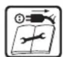
Unplug the mains lead immediately if it has become damaged or has fastened or become entangled in anything. Always unplug the mains lead before changing the router bit or carrying out any maintenance, or service.

Protection class 2
Product description
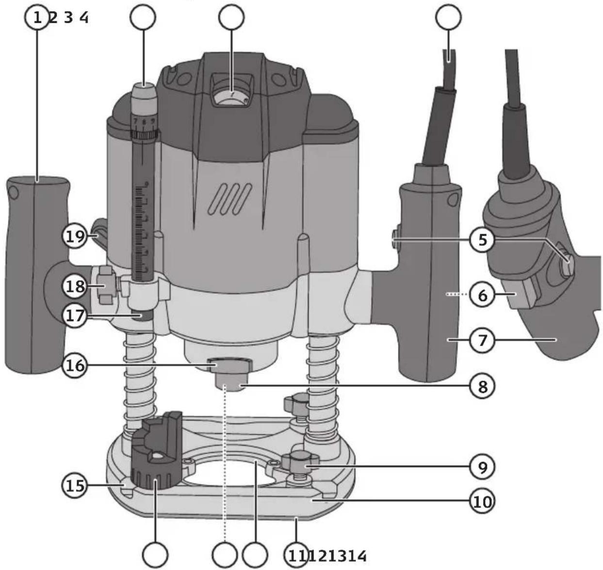
- Left handle
- Depth stop fine-adjustment knob
- Rotation speed selection switch
- Mains lead
- Switch lock button
- Power switch (on/off)
- Right handle
- Collet nut
- Parallel guide locking knob
-
Base plate
-
Sliding plate
- Fixing holes for dust extractor
- Collet chuck 8 mm
- Step limit
- Parallel guide rod track
- Spindle lock
- Depth stop
- Depth stop locking knob
- Height adjustment locking lever
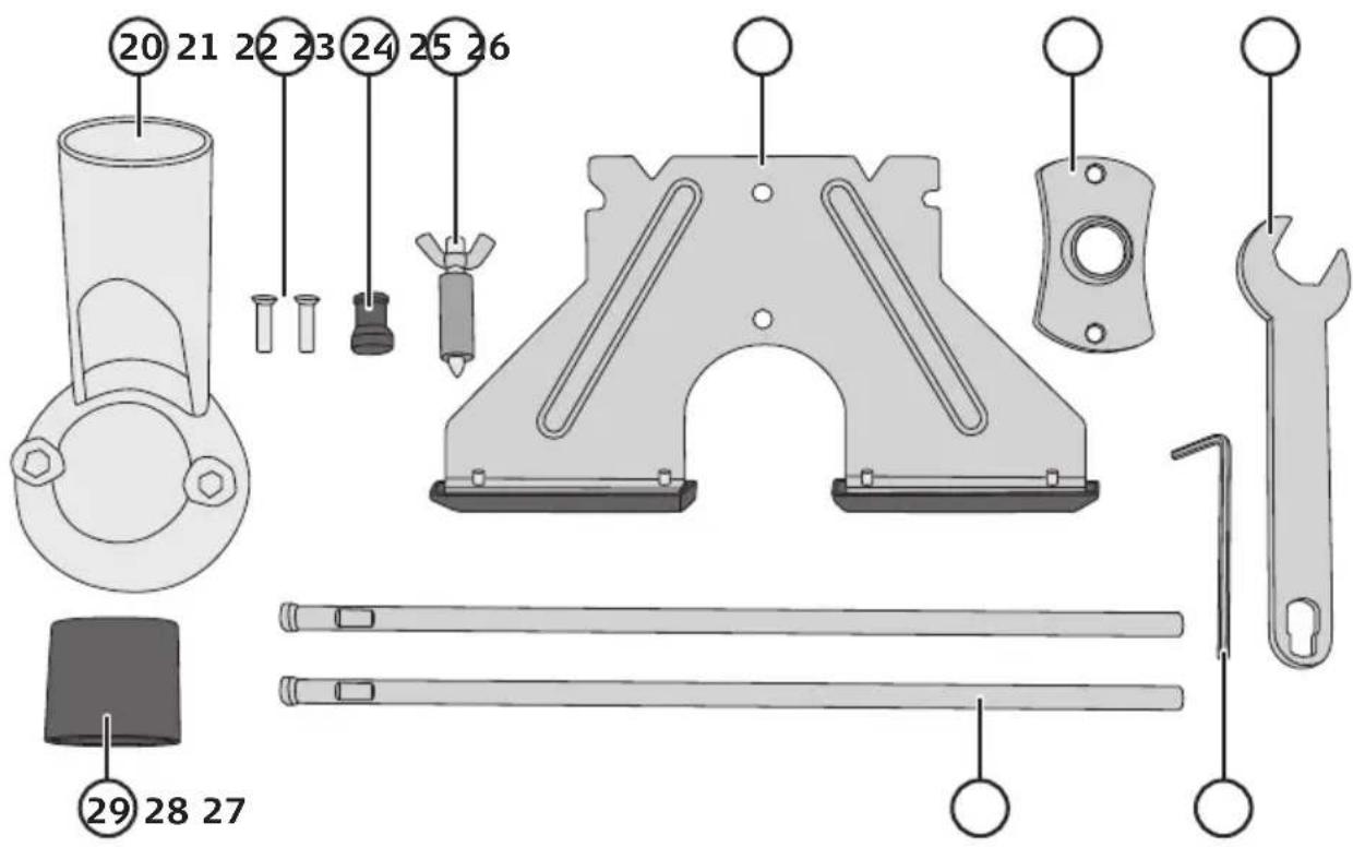
- Dust extraction port adaptor
- Screws for dust port adaptor and template guide
- Collet chuck 6 mm
- Centring pin
- Parallel guide
- Template guide
- Spanner
- Allen key
- Guide rods for parallel guide
- Reducer for dust extraction adaptor
Operating instructions Router cutting fitting
Important!
- Unplug the router before any service or adjustment.
- Bear in mind that the cutter shank diameter must be compatible with both the collet size and speed.
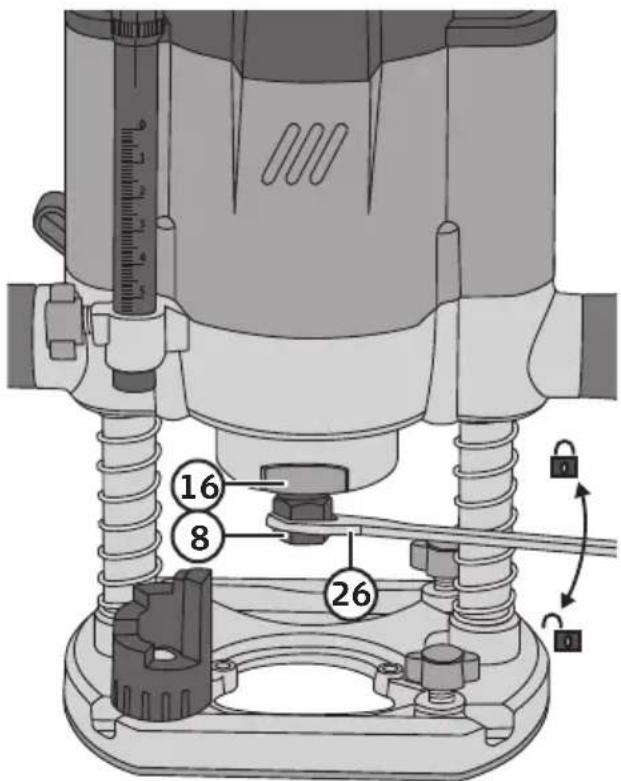
- Turn the router upside down.
- Press in the spindle lock button (16).
- Undo the nut (8) using the spanner (26).
- Insert the cutter using the appropriate collet, 6 or 8 mm.
- Tighten the collet nut using the spanner.
Attaching and adjusting the parallel guide
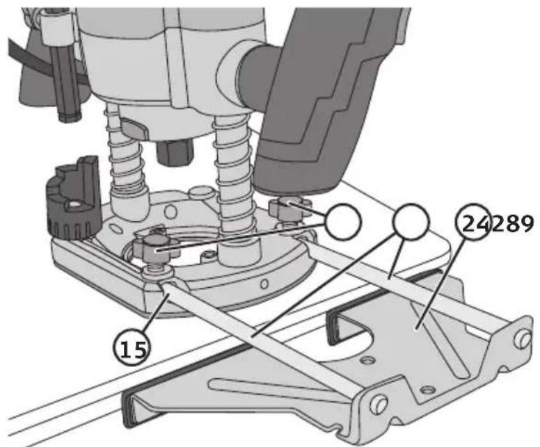
- Secure the two guide rods (28) to the parallel guide (24) using the screws.
- Undo the locking knobs (9).
- Slide the parallel guide rods through the holes (15).
- Adjust to a suitable setting.
- Tighten the locking knobs.
Fitting the centring pin for circle cutting
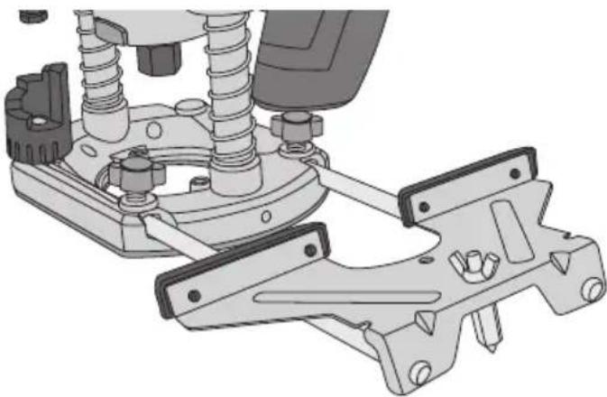
The router can be used to cut arcs and circles with the help of the centring pin.
- Drill a hole in the centre of the circle that is to be cut out.
- Turn the parallel guide upside down and fasten the centring pin into one of the holes.
- Set the correct radius for the circle.
- Tighten the guide rod locking knob.
- Stick the point of the centring pin into the centre hole of the circle to be cut.
- With the router switched off, move the router around the circle to check if it is the right size and make any adjustments.
- Cut the circle in stages, lowering the router cutter about 2 mm on each circuit. Do not try to cut too deeply in one go.
natural_image
Mechanical assembly diagram showing spring and mounting bracket components (no text or labels)Fitting the template guide and dust extraction adaptor
Template guide Dust extraction port adaptor
natural_image
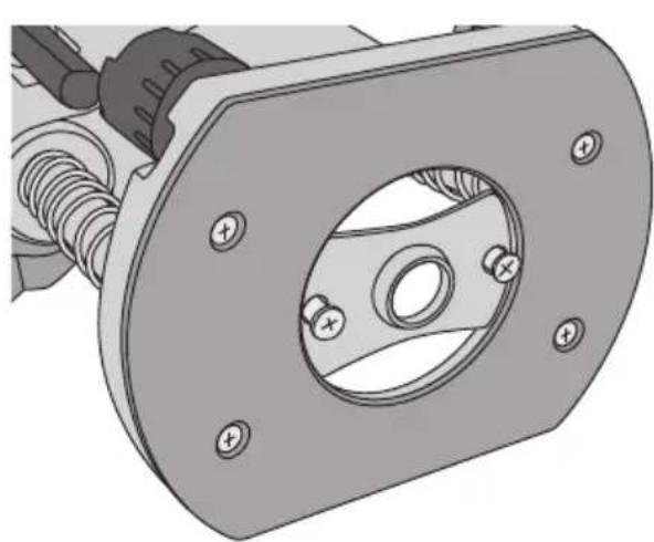
Technical illustration of a mechanical component with a circular recess and bolt holes (no text or symbols)Attach the template guide using the included screws.
natural_image
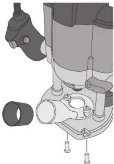
Mechanical component diagram showing a drill bit with attached parts and mounting holes (no text or symbols)Place the dust extraction port adaptor onto the base plate and fasten it with the supplied screws.
Setting cutter depth
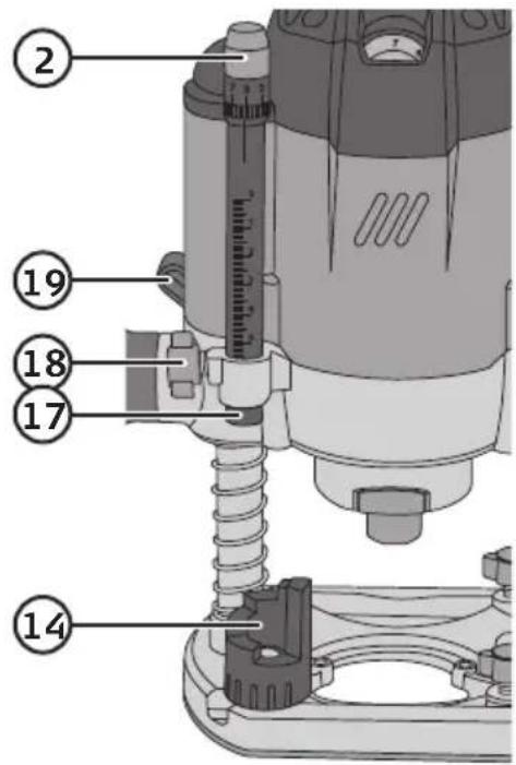
- The router is equipped with a depth stop (17) which is adjusted by turning the locking screw (18).
- When a rough setting has been made fine adjustments can be made using the adjustment screw (2).
- By turning the depth set block (14) the depth of cut can be altered to one of 6 fixed settings.
- The locking lever (19) is for raising or lowering the height of the router body. We recommend that the router is locked when cutting as it is most stable in that position.
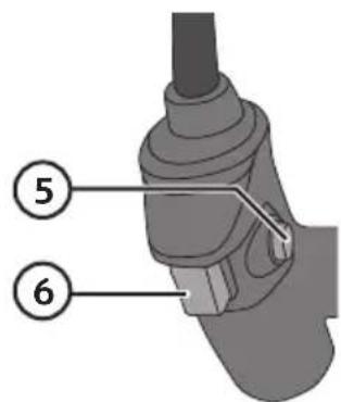
Switching On/Off
Switching on: Hold in the safety catch (5) and the power switch (6).
Switching off: Release the powerswitch.
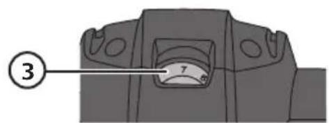
Setting the speed
Select the speed by turning the speed selector (3). After running the tool at low speed for a long time, one should let the motor run at maximum speed for about 3 minutes to cool it down.
Care and maintenance
- If the supply cord is damaged, it must be replaced by the manufacturer, its service agent or similarly qualified persons in order to avoid a hazard.
- Clean the exterior of the router by wiping it with a damp cloth. Use only mild cleaning agents, never solvents or corrosive chemicals. Vacuum them if necessary.
- Keep the motor ventilation openings free from contaminants.
- If the circular saw is not to be used for an extended period, it should be unplugged and stored in a dry location out of reach of children.
Troubleshooting guide
| The router won’t switch on. | Make sure that the mains lead is undamaged and securely plugged into a wall socket.Is the wall socket live? |
| The router runs slowly. | Do not force (apply excessive feed pressure on) the router through the cut. Heavy pressure on the cutter will strain the motor.Is the router cutter blunt or worn? Replace if necessary. |
| Abnormal noise and vibration. | Check that the router cutter is in good condition and is correctly fitted. |
Responsible disposal
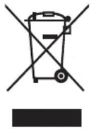
This symbol indicates that this product should not be disposed of with general household waste. This applies throughout the entire EU. In order to prevent any harm to the environment or health hazards caused by incorrect waste disposal, the product must be handed in for recycling so that the material can be disposed of in a responsible manner. When recycling your product, take it to your local collection facility or contact the place of purchase. They will ensure that the product is disposed of in an environmentally sound manner.
natural_image
Symbol of a trash bin with crossed lines indicating no waste or restriction, and a solid black rectangle below (no text or labels)Specifications
Voltage 230 V AC, 50 Hz
Power 1200 W
No-load speed 11 000–30 000 rpm
Plunge depth 55 mm
Collet chuck 8 mm + 6 mm
Sound pressure level (LpA) 90 dB (A), K = 3 dB(A)
Sound power level (LwA) 101 dB(A), K = 3 dB(A)
Vibration value a
$$ _ {h} = 5. 4 \mathrm{m} / \mathrm{s} ^ {2}, K = 1. 5 \mathrm{m} / \mathrm{s} ^ {2} $$
Weight without accessories 2.7 kg
Handöverfräs
Art.nr 18-3616 Modell SDGJ-DMX-1-UK
41-1233 SDGJ-DMX-1
natural_image
Mechanical assembly diagram showing spring and mounting bracket components (no text or labels)natural_image
Technical illustration of a mechanical component with a flanged housing and bolt holes (no text or symbols)natural_image
Mechanical assembly diagram showing a motor with attached components and mounting holes (no text or labels)På/av
natural_image
Symbol of a trash bin with no text or labels, crossed by two diagonal lines and a solid black rectangle below (no text or symbols present)Specifikationer
natural_image
Mechanical assembly diagram showing spring and mounting bracket components (no text or labels)natural_image
Technical illustration of a mechanical component with bolt holes and spring-loaded housing (no text or symbols)natural_image
Technical illustration of a mechanical assembly with no visible text or symbolsTil/frakobling
natural_image
Symbol of a trash bin crossed with no text or labels, accompanied by a blank rectangular block below (no text or symbols present)Spesifikasjoner
Strømforsyning 230 V AC, 50 Hz
Effekt 1200 W
Turtall, trinnløst 11000–30000 o/min (ubelastet)
natural_image
Mechanical assembly diagram showing spring and mounting bracket components (no text or labels)natural_image
Technical illustration of a mechanical component with a circular recess and bolt holes (no text or symbols)natural_image
Mechanical component diagram showing a drill bit with attached parts and mounting holes (no text or symbols)Käynnistys/sammutus
natural_image
Symbol of a trash bin crossed with no text or labels, representing waste sorting or disposal (no text present)Tekniset tiedot
Äänenpaine (LpA) 90 dB (A), K = 3 dB(A)
Melutaso (LwA) 101 dB (A), K = 3 dB(A)
Tärinäarvo a
$$ _ {\mathrm{h}} = 5, 4 \mathrm{m} / \mathrm{s} ^ {2}, K = 1, 5 \mathrm{m} / \mathrm{s} ^ {2} $$
natural_image
Technical illustration of a vehicle suspension system with springs and brackets (no text or symbols)natural_image
Technical illustration of a mechanical component with a circular housing and bolt holes (no text or symbols)natural_image
Technical illustration of a mechanical device with labeled parts (no text or symbols present)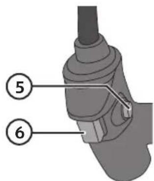
natural_image
Symbol of a trash bin crossed with no visible text or labelsTechnische Daten
Declaration of Conformity
Declares that this product complies with the requirements of the following directives and standards
Machinery Directive 2006/42/EC
EN 60745-1: 2009/A11: 2010
EN 60745-2-17: 2010
EMC Directive 2014/30/EU
EN55014-1:2006/A2:2011
EN55014-2:2015
EN61000-3-2:2014
EN61000-3-3:2013
Henrik Alfredsson
Manager Technique & Quality
Insjön, Sweden, 2018-07-17
Sverige
Postal 10 - 13 Market Place
Kingston Upon Thames
Surrey
KT1 1JZ
Deutschland
Kundenservice Hotline: 040 2999 78111
E-Mail: kundenservice@clasohlson.de
Homepage
www.clasohlson.de
- Important!
- Viktig information:
- Safety
- General Power Tool Safety Warnings
- 1) Work area safety
- 2) Electrical safety
- 3) Personal safety
- 4) Power tool use and care
- 5) Service
- Additional safety instructions for routers and trimmers
- Vibration
- Product safety symbols
- Operating instructions Router cutting fitting
- Attaching and adjusting the parallel guide
- Fitting the centring pin for circle cutting
- Fitting the template guide and dust extraction adaptor
- Setting cutter depth
- Switching On/Off
- Setting the speed
- Care and maintenance
- Troubleshooting guide
- Responsible disposal
- Specifications
- Handöverfräs
- På/av
- Specifikationer
- Til/frakobling
- Spesifikasjoner
- Käynnistys/sammutus
- Tekniset tiedot
- Technische Daten
- Declaration of Conformity
- Sverige
- Deutschland
Brand : Cocraft
Model : HR1200
Category : Milling machine