
LS405 - Cutting machine Cocraft - Free user manual and instructions
Find the device manual for free LS405 Cocraft in PDF.


| Product Type | Cutting Machine |
| Brand | Cocraft |
| Model | LS405 |
| Dimensions (L x W x H) | Approx. 500 x 200 x 300 mm |
| Weight | Approx. 5 kg |
| Power Supply | 220-240V AC, 50/60 Hz |
| Power Consumption | 100 W |
| Cutting Width | 300 mm |
| Cutting Thickness | Up to 2 mm |
| Blade Type | Tungsten carbide |
| Cutting Speed | Adjustable, 10-50 mm/s |
| Material Compatibility | Paper, cardstock, vinyl, fabric |
| Blade Depth Adjustment | Yes, manual |
| Display | LED control panel |
| Safety Features | Blade guard, auto shut-off, thermal overload protection |
| Maintenance | Clean blade with dry cloth; lubricate guide rails periodically |
| Spare Parts Available | Replacement blades, cutting mat, drive belts |
| Repairability | Modular design; user-replaceable blade and belt |
| Included Accessories | Cutting mat, 3 blades, user manual |
| Warranty | 2 years |
| Certification | CE, RoHS |
Frequently Asked Questions - LS405 Cocraft
User questions about LS405 Cocraft
0 question about this device. Answer the ones you know or ask your own.
Ask a new question about this device
Download the instructions for your Cutting machine in PDF format for free! Find your manual LS405 - Cocraft and take your electronic device back in hand. On this page are published all the documents necessary for the use of your device. LS405 by Cocraft.
USER MANUAL LS405 Cocraft
Read the entire instruction manual carefully and make sure that you fully understand it before you use the equipment. Keep the manual for future reference.
Viktig information:
natural_image
Technical line drawing of a mechanical device with wheels and a central housing (no text or symbols)Art.no Model
40-8982
65650
Ver. 20160210
Original instructions
Bruksanvisning i original
Originalbruksanvisning
Please read the entire instruction manual before using the product and then save it for future reference. We reserve the right for any errors in text or images and any necessary changes made to technical data. If you have any questions concerning technical problems please contact our Customer Services.
Safety
General safety instructions for power tool use
Warning: When using this machine all basic safety precautions must be followed to minimise the risk of fire, electrocution and personal injury. Read these instructions carefully before using the product and keep them for future reference.
- Keep the work area tidy.
Cluttered surfaces and benches invite accidents. - Take stock of your working environment.
Do not expose the machine to rain. Do not use the machine in moist or wet areas. Keep the working area well lit. Never operate the machine near flammable liquid or gas. - Reduce the risk of electric shocks.
Avoid body contact with earthed objects such as pipes, radiators, ovens or refrigerators. - Keep other people at a safe distance.
Do not allow anyone not involved in the work process to touch the machine or its electric cable, especially children. Keep all bystanders at a distance. - Store the machine in a safe place.
When your machines are not in use, keep them in a locked, dry area, away from children. - Do not overload the machine.
The tool will work better and safer at the feed rate for which it was intended. - Use the correct machine.
Do not try to use small machines to perform jobs requiring more powerful machines. Do not use a machine for a purpose for which it was not designed, e.g. using a circular saw for lopping branches off trees or cutting timber. - Wear suitable attire.
Do not wear loose-fitting clothing or jewellery; they could be caught in moving parts. Non-slip shoes are recommended for outdoor work. Wear a hairnet or similar if you have long hair. - Always wear safety glasses.
Wear safety glasses. Use a dust mask or dust filter when working in dusty environments. - Use dust extractors.
If the machine is equipped with or connected to a dust extractor/collector, make sure that it is turned on and used correctly. - Do not abuse the mains lead.
Do not pull or tug the mains lead when unplugging the machine, grip and pull the plug itself. Make sure that the mains lead does not come into contact with heat, oil, or sharp edges. - Do not overreach.
Make sure that you stand steady and balanced all times. - Maintain power tools in top condition.
Make sure that your machine is clean and that any cutting edges are sharp for maximum effect and best results. Follow the manual's recommendations regarding lubrication and replacement of accessories. Inspect the mains lead regularly. If it is damaged it should be replaced by a qualified service technician. Inspect all leads and cables regularly to check for any damage. Make sure that the machine's handles and controls are clean, dry and free from oil, grease etc. - Turn the power off.
Push in the emergency stop button and pull the plug out before servicing or changing any blades, drill bits, cutters or sanding discs. -
Remove all spanners and repair tools.
Make a habit of checking to make sure that the machine is free of all spanners and tools before turning the power on. -
Avoid accidental starts.
Do not walk around with your finger on the trigger of a power tool if it is plugged in. Make sure that the ON/OFF switch is set to OFF before plugging in any power tool.
- Use the correct extension leads.
If you use extension leads outdoors, only use those designed for outdoor use. Only use extension leads with thick enough diameter core wires and roll out the whole lead.
- Use common sense and be careful.
Think before carrying out any task, so that it is carried out safely. Never operate machines when you are tired, under the influence of medicine etc.
-
Check the following before turning the machine on:
-
That all guards and other parts are whole and in working order.
- That moving parts are free and correctly aligned.
- That no moving parts can get caught.
- That there are no visible defects.
- Other factors that could influence work execution.
A safety guard or any other part that is damaged should be repaired by a tradesman or replaced.
Damaged power leads and switches must always be replaced by a tradesman or qualified service centre.
Never operate the machine if you cannot stop or start it comfortably.
- Use only recommended accessories.
The use of non-recommended accessories could lead to accidents or injuries.
- Should only be repaired by a qualified technician.
This machine conforms to current safety requirements. Repairs to the machine should only be carried out by a tradesman using original spares; otherwise the machine could cause an accident or injury.
Specific safety instructions for log saws
- Keep your hands and fingers well away from the blade and use, as always when operating machinery, your common sense and take care whilst working.
- Make sure that there are no bystanders or pets close to the machine, sharp splinters can be ejected by the blade with great force.
- Make sure that the blade is fitted the right way round and that the flange nuts of the blade are fully tightened before use.
• Always keep the blade sharp.
• Always inspect the blade for damage and cracks before use. - Check that the emergency stop button works.
- Always unplug the machine from the power supply before making any adjustments or when you have stopped work.
- Only use an extension lead with a conductor cross-sectional area of at least 1.5 mm^2 and which is approved for outdoor use. When using a cable reel, always unwind the cable completely for better cooling and check the cable and other equipment for damage.
- Never use the log saw in rain or wet conditions.
- Never use the machine if the electrical cable, power switch, safety guard or any other part is damaged; faulty parts must be replaced by a qualified tradesman.
- Note: Check regularly to ensure that all screws and nuts are tight.
- Always use a residual current device (RCD or RCCB) which trips at < 30 mA between the log saw and the power supply.
Safety symbols

Read the entire manual and save it for future use.

Wear a visor or safety goggles.
Always wear safety goggles or safety glasses with side shield protection when operating this tool. Normal spectacles only have shock-proof glass and do not offer effective protection from impacts. Flying particles and objects.

Wear ear protection.
Always wear ear protectors/defenders if the noise level exceeds 85 dB(A).

Wear safety gloves.
Wear protective gloves when handling saw blades, changing blades and operating the machine.

Wear safety footwear.
Wear protective boots or safety shoes with non-slip soles.

Never use the log saw in rain or wet conditions.
Do not expose the machine to rain. Do not use the machine in moist or wet environments.
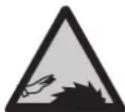
Warning: Rotating blade.
Keep hands away from the blade when it is rotating; never leave a rotating blade unattended.

Disconnect power when not in use.
Push in the emergency stop button and unplug the machine when you have stopped work and before servicing or adjusting the machine.

Keep children out of the work area.
Supervise children and pets so that they remain a safe distance away from the machine.

Keep visitors a safe distance away from the work area whilst the machine is in operation.
This log saw is only intended to be operated by one person.
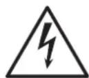
Warning: Risk of electric shock.
Follow all the safety precautions and instructions in the instruction manual.

Failure to follow the safety instructions could result in serious injury or fatality.
Package contents
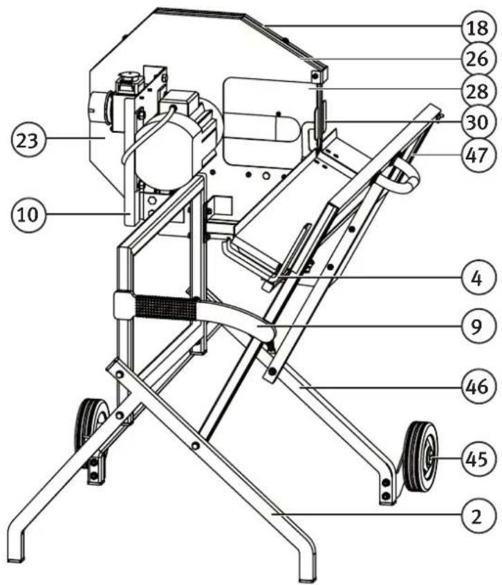
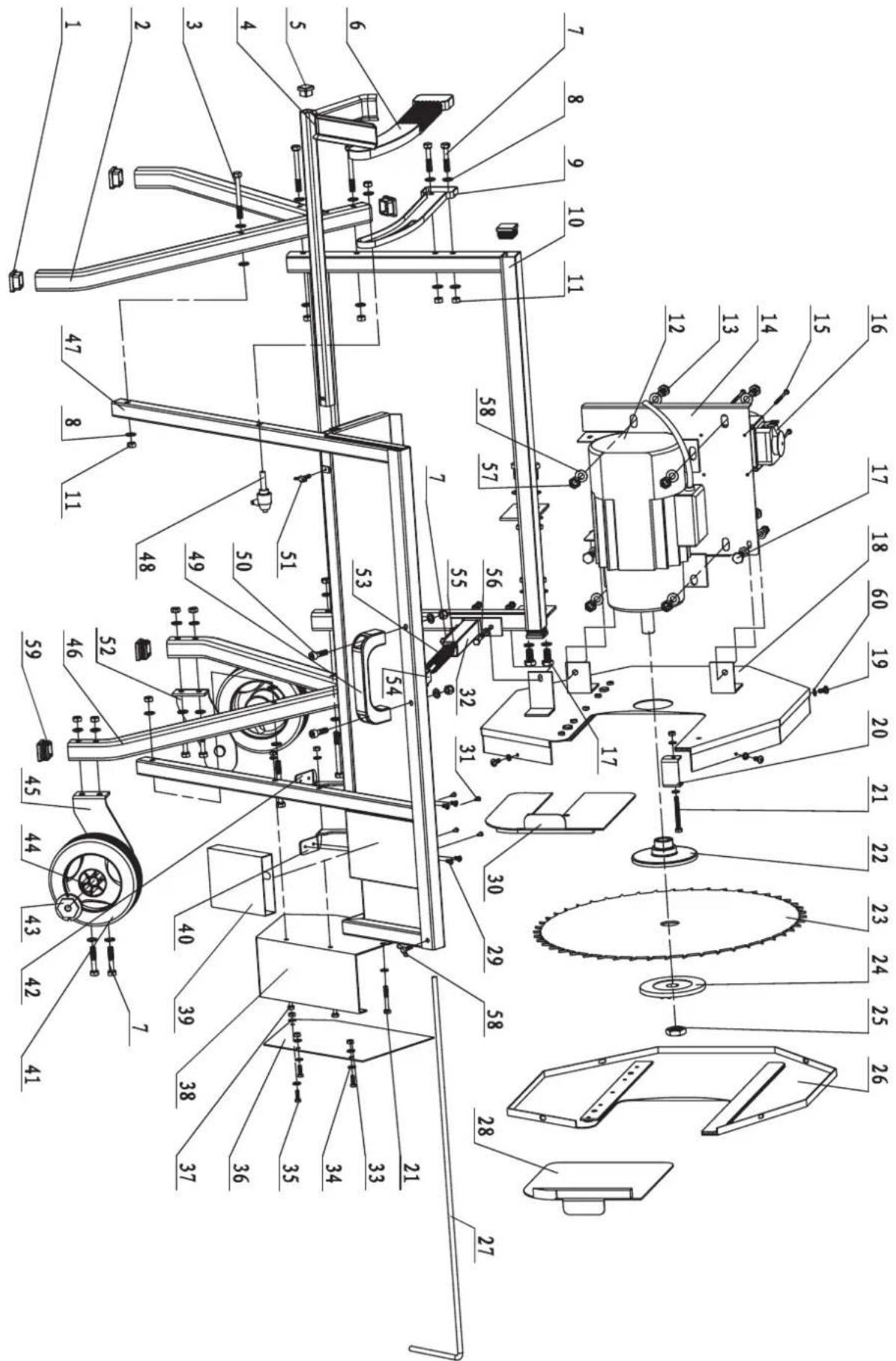
The list of contents and assembly instructions refer to the exploded view at the end of this instruction manual, where all parts are numbered in sequence.
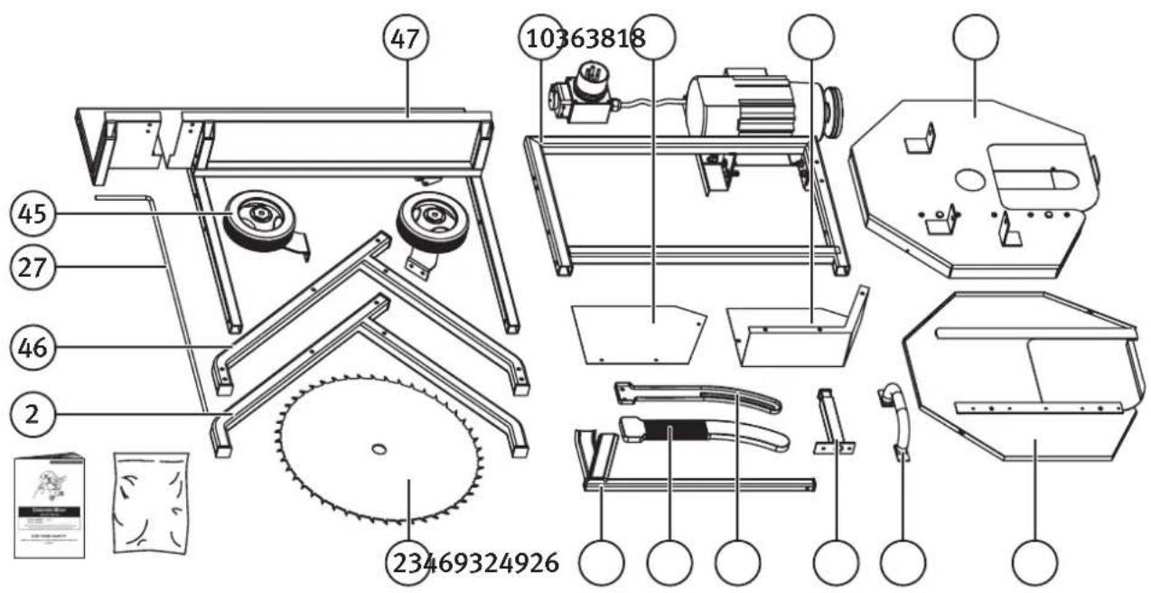
47.Cradle
10. Support stand with motor and on/off switch/emergency stop
36. Lower outerblade guard
38. Lower innerblade guard
18. Inner (moving) guard
45. Wheel assembly
27.Log stop bar
46. Leg (right)
2. Leg (left)
23.Saw blade
4. Log support yoke
6. Rubber cover for cradle connector (9)
9. Cradle connector
32. Return spring
49. Handle
26. Outer (moving) guard
- Bag of fasteners A, B, C, D, E and F
- Instruction manual
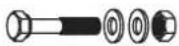
The following fasteners for assembly are in the bag
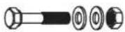
Note: The number and size of the fasteners can change if the product is modified.
A
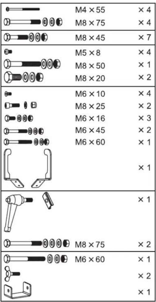
B

C


D






E






Parts
-
Saw blade (inside guard)
-
Support stand with motor and on/off switch/emergency stop
18, 26. Blade guard
28, 30. Moving guard
-
Cradle
-
Log support yoke
-
Cradle connector with rubber cover (6)
2,46. Legs
- Wheel assembly
Assembly
Warning: The log saw must not be switched on until it has been completely assembled and all the component parts have been securely tightened.
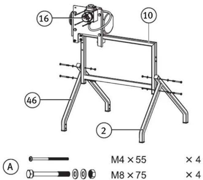
Step 1
-
Join the left leg (2) and the right leg (46) to the motor support (10) using:
-
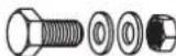
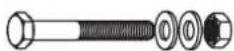
2 × bolt M8 × 75
- 2 × lock nut M8
-
8 × washer M8
-
Mount the on/off switch (16) to the motor support using 4 × screws M4 × 55.
Note: Rear view of the log saw.
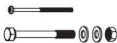
M4 × 55 × 4
M8 × 75 × 4
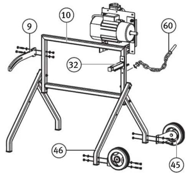
Step 2
-
Bolt the wheel assembly (45) onto the right leg (46) using:
-
4 × bolt M8 × 45
- 8 × washer M8
-
4 × lock nut M8
-
Attach the cradle connector (9) (can also be used as a handle) onto the support stand using:
-
2 × bolt M8 × 45
- 4 × washer M8
-
2 × lock nut M8
-
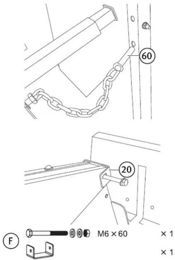
Attach the return spring (32) onto the support stand (10). Insert the bolt with a flat washer on into the second hole from the top.
-
1 × bolt M8 × 45
- 2 × washer M8
-
1 × lock nut M8
-
Fit the bolt attached to the chain (60) in the hole under the return spring (32).
B
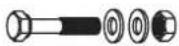
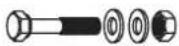
M8 × 45
× 7
Step 3
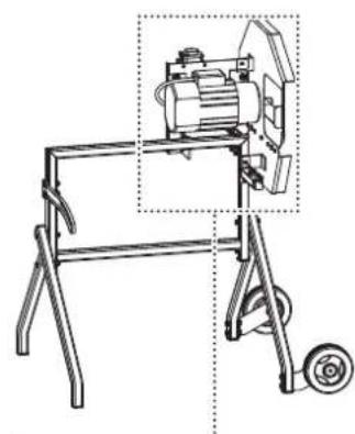
Mount the inner blade guard (18) (the part of the blade guard closest to the motor):
-
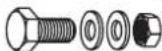
Fit the 2 short bolts (17) with washers through the inner blade guard. Pass the bolts through the elongated holes in the motor support plate (14), fit washers onto the bolts and fix with lock nuts.
-
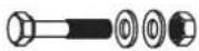
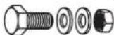
2 × bolt M8 × 20
- 2 × washer M8
-
2 × lock nut M8
-
Make sure that the inner blade guard is centered on the drive shaft, adjust if necessary.
-
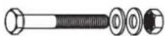
Fit a washer onto the long bolt (56) and then pass it through the front bracket of the inner blade guard and the upper hole for the return spring (32) on the support stand. Tighten the lock nut.
-
1 × bolt M8 × 50
- 2 × washer M8
- 1 × lock nut M8
natural_image
Technical line drawing of a mechanical device with wheels and a motor, no text or symbols present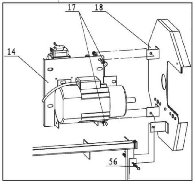
C
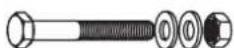
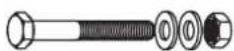
M8 × 50
× 1
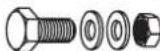
M8 × 20
× 2
Step 4
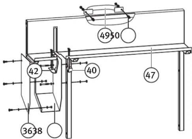
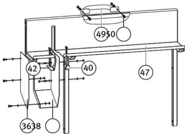
Assemble the cradle:
- Attach the lower blade guard to the cradle.
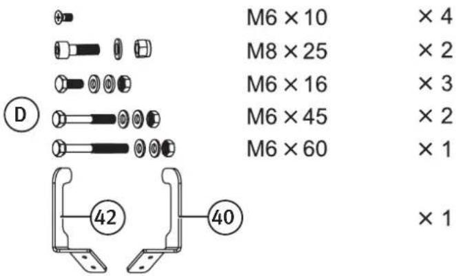
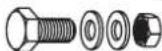
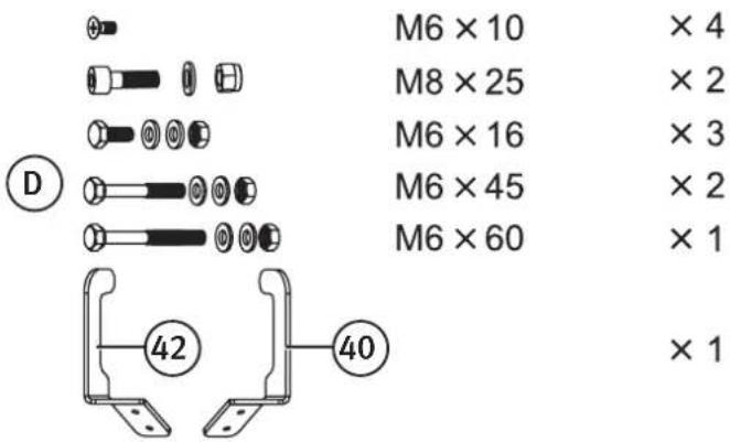
- Screw the parts of the lower blade guard (38 and 36) together using 3 screws M6 × 16, washers and nuts.
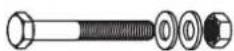
- Screw the assembled lower blade guard onto the cradle (47) using 2 screws M6 × 45, washers and nuts and 1 screw M6 × 60, washer and nut.
- Fix the handle (49) to the cradle using 2 screws M8 × 25 (50) and lock nuts.
- Screw the hook arms (40, 42) down using the countersunk M6 × 10 screws.
Step 5
-
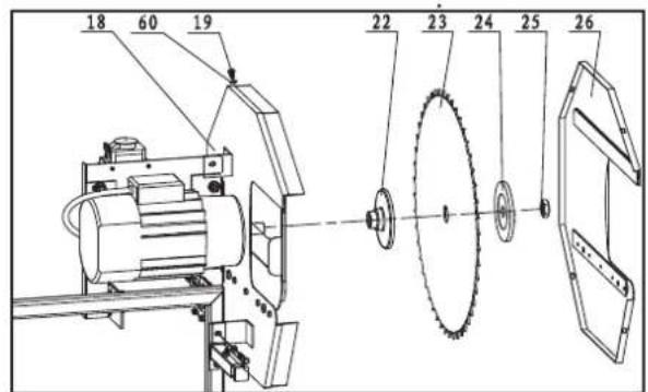
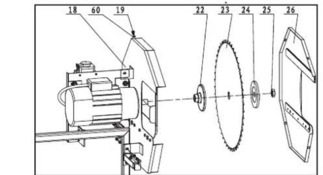
Install the saw blade and blade guard:
-
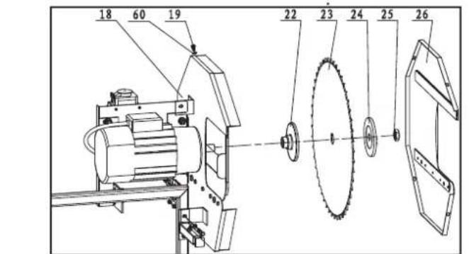
First fit the inner retaining disc (22) onto the drive shaft.
- Then fit the saw blade (23) onto the drive shaft*. Press the saw blade against the inner retaining disc and hold it in place. Fit the outer retaining disc (24) up against the saw blade, screw on the blade nut (25) and tighten it.
Note: The inner blade retaining disc is shouldered and has an inner barrel which fits into the centre hole of the saw blade to ensure that it is centred.
Make sure that the blade is centred on the retaining discs and that it rotates in the correct direction before tightening the securing nut.
Warning: Use the included blade nut spanner and locking spanner, and wear safety gloves.
Warning: Be careful when tightening the blade nut so as not to slip and cut yourself on the blade.
*Note: Install the blade in accordance with the direction of rotation arrow markings on the blade and the blade guard.

-
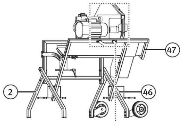
Screw the outer blade guard on as shown.
-
Fit the outer blade guard (26) onto the inner blade guard.
-
Fasten it in place using the four small screws (19) and washers (60).
-
Mount the cradle between the right (46) and left (2) legs.
-
Line up the holes in the cradle with the corresponding holes in the legs and pass a M8 × 75 bolt through from the outside on each side. Place one washer next to the head of the bolt, one between the cradle and the leg and one next to the nut.
- Remember to place washers between the cradle (47) and the right/left leg during assembly.
Step 6
Attach the moving guard, on the inside of the inner and outer blade guard.
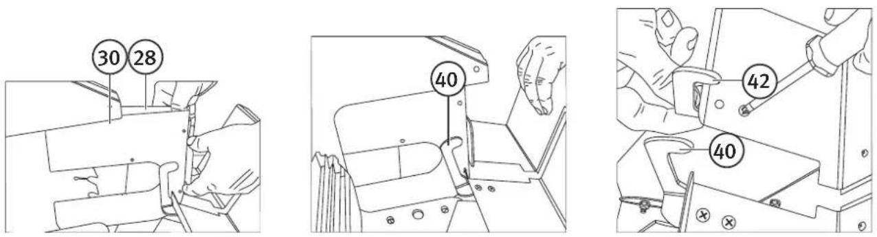
- Slide the two moving guards (30 and 28) into the slots on the inside of the inner and outer blade guards.
- The hook arms (40 and 42) on the cradle should then be placed on the inside of the protrusions on the moving guard. Turn the hook arms as shown in the figure.
- The moving guard which has an opening with a moving plate should be fitted to the inner blade guard closest to the motor (see figure).
Note: Make sure that the blade passes cleanly through the gap in the guard without touching. If not, loosen the screws in the guard and adjust it as necessary.
The motor is fitted with a brake which makes the blade difficult to turn by hand when the motor is switched off.
Step 7
Screw the other bolt (60) in the chain into the hole in the cradle.
Step 10
Attach the bracket (20) holding the moving guards in place as shown. Use the long bolt with 2 washers and a lock nut. Do not tighten it too much.
Step 9
natural_image
Technical line drawing of a mechanical tool with a labeled section (E) and a cross symbol (×1), no readable text or symbols present.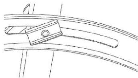
natural_image
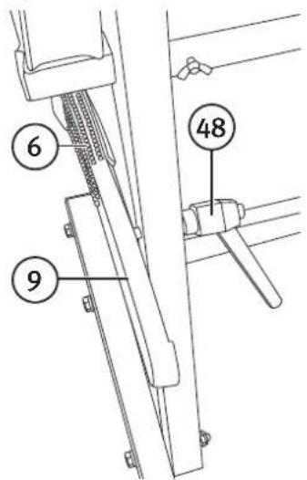
Technical line drawing of a mechanical clamp or bracket component (no text or symbols)Attach the cradle connector (9) locking knob.
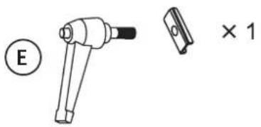
- Lock the cradle connector (9) to the cradle using the special nut, washer and the locking knob (48).
- Push the rubber cover (6) firmly onto the cradle connector.
Step 10
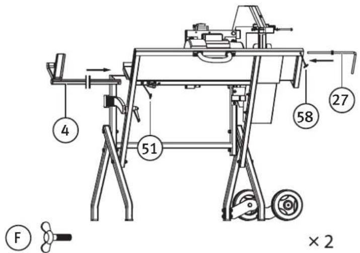
Mount the log support yoke (4) and log stop bar (27) into the cradle, tighten using the wing nuts (51, 58).
Exploded view
Preparations
- Familiarise yourself with the operation of the log saw. Make sure that you can work in an ergonomic working position and that you can work safely. Ensure that you can reach the emergency stop button.
- Place the log saw on firm, level surface providing a comfortable working height. Ensure that there is adequate lighting for the work to be carried out safely.
- Set the log saw to the desired cutting length.
- Plug the mains lead into an electrical socket, preferably via an RCD. Take care to position the mains lead where it will not hinder the work or be damaged by the work with the log saw.
Emergency stop
The red button is an emergency stop button enabling the log saw to be switched off quickly and easily if necessary.
Using the saw
- Switch the saw on using the green button and let the blade come up to full speed.
- Place a log into the cradle so that it will not move whilst it is being cut.
- Raise the cradle towards the saw blade in a smooth and steady motion.
- The motor is protected by a thermal overload circuit breaker which cuts power to the no-volt release switch if the motor becomes too hot. The motor could overheat if the saw is overloaded or used continuously for a long time. The thermal overload protection will automatically reset after about 10 minutes depending on the ambient temperature. When the thermal overload protection has reset, the RCD and on/off switch will work normally again.
Maintenance
Installing and changing the saw blade:
• Always wear gloves when handling the saw blade and formulate a plan of action before beginning.
• Make sure that the contact surfaces between the blade and the retaining discs are clean before beginning assembly.
- Use the included blade nut spanner and locking spanner.
Other maintenance:
- Always unplug the mains lead and wait until the saw blade has come to a complete stop before beginning any maintenance work. Move the plug well away from the electrical socket so that no-one can plug the saw in without your knowledge.
- Ensure that the mains lead, plug and on/off switch are all in good condition and undamaged.
- Clean all the parts of the log saw with a brush and dry rags.
- Store the log saw in a dry, clean and non-corrosive location, out of the reach of children.
- Check regularly to ensure that all screws and nuts are tight.
- The perforated anti-slip grips which prevent the log from rotating in the cradle should also be cleaned whenever necessary.
Responsible disposal
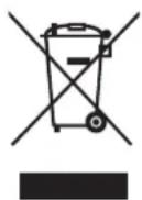
This symbol indicates that this product should not be disposed of with general household waste. This applies throughout the entire EU. In order to prevent any harm to the environment or health hazards caused by incorrect waste disposal, the product must be handed in for recycling so that the material can be disposed of in a responsible manner. When recycling your product, take it to your local collection facility or contact the place of purchase. They will ensure that the product is disposed of in an environmentally sound manner.
Technical specifications
Motor voltage 230 V AC, 50 Hz
Motor power 1600 W, S6 40%, 2850 RPM
Protection class IP44
Capacity ∅ 30–140 mm
Blade 405 × 30 × 3 mm, 40 teeth
Weight 42.6 kg
Sound power level (LwA) 108.6 dB(A)
Sound pressure level (LpA) 95.1 dB(A)
Vedkap
Montering
B
M8 × 45
× 7
Steg 3
natural_image
Technical line drawing of a mechanical device with wheels and a motor (no text or symbols)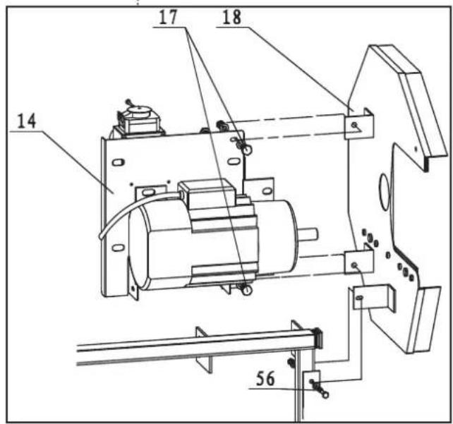
C
M8 × 50
× 1
M8 × 20
× 2
Steg 4
Montera vaggans delar:

Förberedelser
47.Vugge
Montering
B
M8 × 45
× 7
Trinn 3
Monter det indre beskyttelsesdekselet (18) (den delen av dekselet som sitter nærmest motoren):
natural_image
Technical line drawing of a mechanical device with wheels and a motor (no text or symbols)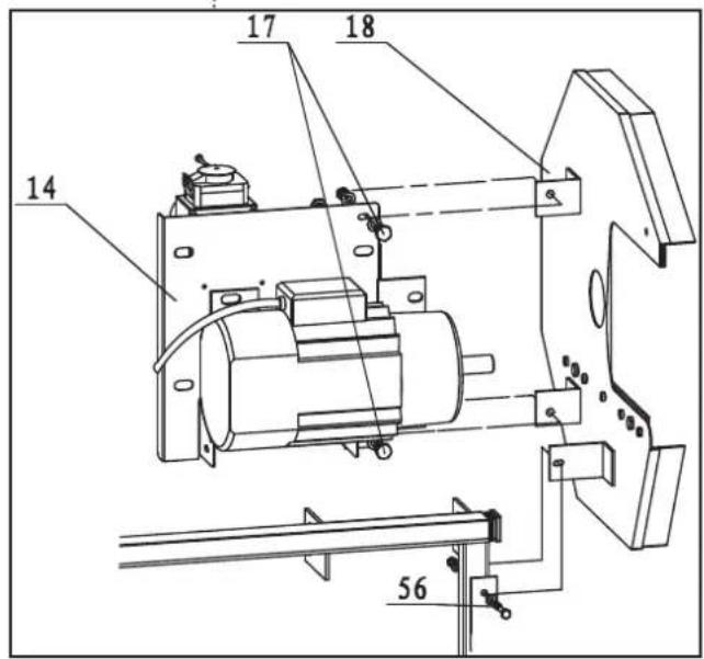
C
M8 × 50
× 1
M8 × 20
× 2
Trinn 4
Monter vuggen:
- Monter det nedre beskyttelsesdekselet til vuggen.
- Skru sammen det nedre beskyttelsesdekselets deler (38 og 36) med 3 skruer, skiver og mutre M6 × 16.
- Fest det ferdig monterte dekselet på vuggen (47) med 2 skruer, skiver og mutre M6 × 45 og en skrue, skive og mutter M6 × 60.
- Monter håndtaket (49) til vuggen med 2 skruer og låsemutre M8 × 25 (50).
- Fest bøylene (40, 42) med de forsenkede skruene, M6 × 10.
Trinn 5
-
Monter sagbladet og beskyttelsesdekselet:
-
Plasser først den indre klingeflensen (22) på motorakselen.
- Plasser deretter sagblad (23) på motorakselen*. Trykk sageklingen fast på den indre klingeflensen og hold fast. Plasser deretter den ytre klingeflensen (24) utenfor sageklingen, fest klingemutteren (25) og trekk til.
Obs! Den indre klingflensen har en ansats som passer til klingens sentrumshull (det trengs ingen løs bussning). Påse at klingen sentreres på klingflensen og at den roterer i riktig retning før du trekker til!
Forberedelser
47.Syöttökouru
Asennus
B
M8 × 45
× 7
Kohta 3
natural_image
Technical line drawing of a mechanical device with wheels and a motor (no text or symbols)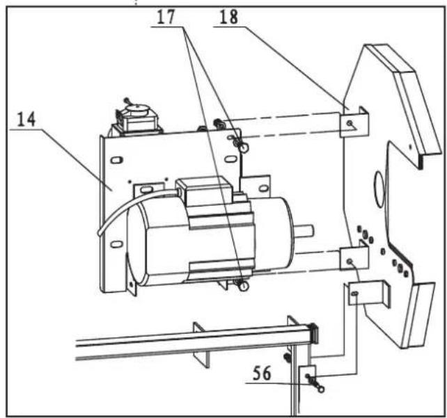
C
M8 × 50
× 1
M8 × 20
× 2
Kohta 4

natural_image
Technical line drawing of a mechanical clamp or bracket component (no text or symbols)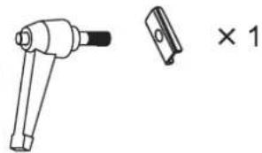
natural_image
Technical line drawing of a mechanical tool with a separate cross-sectional view (no text or symbols)Esivalmistelut
47.Wippe
Montage
B
M8 × 45
× 7
Schritt 3
natural_image
Technical line drawing of a mechanical device with wheels and a motor (no text or symbols)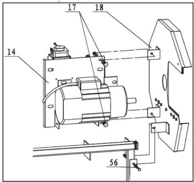
C
M8 × 50
× 1
M8 × 20
× 2
Schritt 4
Vorbereitungen
Declaration of Conformity
Declares that this product complies with the requirements of the following directives and standards
Machinery Directive 2006/42/EC
EMC Directive 2004/108/EC
Low Voltage Directive 2006/95/EC
EN 1870-6/A1:2009 EN
55014-1:2006+A1:2009+A2:2011
EN 55014-2:1997+A1:2001+A2:2008
EN 61000-3-2:2006+A1:2009+A2:2009
EN 61000-3-3:2008
EC type certificate, no. M6A120966014026
Issued by the following notified body:
Manager Technique & Quality
Insjön, Sweden, 2016-02-08
Sverige
10 - 13 Market Place
Kingston Upon Thames
Surrey
KT1 1JZ
Deutschland
- Viktig information:
- Safety
- General safety instructions for power tool use
- Specific safety instructions for log saws
- Safety symbols
- Package contents
- The following fasteners for assembly are in the bag
- Parts
- Assembly
- Step 1
- Step 2
- Step 3
- Step 4
- Step 5
- Step 6
- Step 7
- Step 10
- Preparations
- Emergency stop
- Using the saw
- Maintenance
- Responsible disposal
- Technical specifications
- Vedkap
- Montering
- Steg 3
- Steg 4
- Förberedelser
- Trinn 3
- Trinn 4
- Monter vuggen:
- Trinn 5
- Forberedelser
- Asennus
- Kohta 3
- Kohta 4
- Esivalmistelut
- Montage
- Schritt 3
- Schritt 4
- Vorbereitungen
- Declaration of Conformity
- Sverige
- Deutschland
Brand : Cocraft
Model : LS405
Category : Cutting machine