
HS 400-DE - Water pump Cocraft - Free user manual and instructions
Find the device manual for free HS 400-DE Cocraft in PDF.


| Product Type | Water Pump |
| Brand | Cocraft |
| Model | HS 400-DE |
| Power Supply | 230 V ~ 50 Hz |
| Power Consumption | 400 W |
| Max Flow Rate | 4000 L/h |
| Max Head | 35 m |
| Max Immersion Depth | 7 m |
| Max Liquid Temperature | 35 °C |
| Connection Size | 1" (25 mm) external thread |
| Pump Type | Submersible |
| Material | Stainless steel and plastic |
| Dimensions (L x W x H) | 180 x 150 x 300 mm |
| Weight | 4.5 kg |
| Protection Class | IPX8 |
| Fuse | 10 A (slow-blow) |
| Filter | Built-in mesh filter |
| Maintenance | Clean filter regularly, check seals |
| Storage | Drain and store dry in frost-free place |
| Warranty | 2 years |
Frequently Asked Questions - HS 400-DE Cocraft
User questions about HS 400-DE Cocraft
0 question about this device. Answer the ones you know or ask your own.
Ask a new question about this device
Download the instructions for your Water pump in PDF format for free! Find your manual HS 400-DE - Cocraft and take your electronic device back in hand. On this page are published all the documents necessary for the use of your device. HS 400-DE by Cocraft.
USER MANUAL HS 400-DE Cocraft
Read the entire instruction manual carefully and make sure that you fully understand it before you use the equipment. Keep the manual for future reference.
Viktig information:
natural_image
Blue and silver water purifier device with attached pipe fitting, placed on wooden surface (no visible text or symbols)Art.no Model
40-9034
LKS-404PS
Ver. 20160524
Original instructions
Bruksanvisning i original
Originalbruksanvisning
Stainless Steel Submersible Pump
Art.no 40-9034 Model LKS-404PS
Please read the entire instruction manual before using the product and then save it for future reference. We reserve the right for any errors in text or images and any necessary changes made to technical data. If you have any questions concerning technical problems please contact our Customer Services.
Safety
- This appliance can be used by children aged from 8 years and above and persons with reduced physical, sensory or mental capabilities or lack of experience and knowledge if they have been given supervision or instruction concerning use of the appliance in a safe way and understand the hazards involved.
• Children shall not play with the appliance. - Cleaning and user maintenance shall not be made by children without supervision.
- Always use a residual current device (RCD or RCCB) which trips at < 30 mA between the pump and the power supply.
- Always inspect the pump before using it, especially the mains lead and plug. Never use the pump if it is damaged.
- If the supply cord is damaged, it must be replaced by the manufacturer, its service agent or similarly qualified persons in order to avoid a hazard.
- Make sure that any electrical connections (extension lead, RCD, etc.) are placed in a dry place and protected from overflowing water and floods.
- Do not expose the mains lead to extreme heat, oil or sharp edges.
- The pump is not designed for continuous use.
-
Protect the pump from frost.
-
The pump is suitable for pumping clean or muddy water with a maximum particle size of 5 mm and washing water. Bear in mind that sand and other abrasive substances in the liquid that is pumped will increase the wear and tear and reduce the capacity of the pump.
- The pump must never be used in a swimming pool.
- The pump is waterproof and submersible to a depth of max 7 m.
- Make sure that the pressure head does not exceed 7 m.
- The pump must not be used for corrosive, combustible or explosive liquids such as petrol, kerosene or thinners. Neither must the pump be used for grease, oil, brackish water, seawater, urine or toilet sewage water.
- The temperature of the pumped liquid must not be greater than 35^ C.
- Dry-running should be avoided, as this soon wears the pump out. Turn off the pump as soon as water has stopped coming out of the hose.
- Avoid running the pump with the discharge outlet closed for more than ten minutes.
- The pump has a built-in thermal motor protection and automatically shuts off when it gets overheated. The motor starts again automatically when the motor has cooled.
- If chlorinated water, such as swimming pool water, has been pumped, clean water should be pumped afterwards to rinse out the pump.
Product description
The pump is intended for domestic use in the homes and gardens. Suitable uses:
• Emptying containers
- Pumping water from springs and barrels
- Bilge pumping boats
• Circulating water for limited periods
- Upper outlet (1¼" female thread)
- Plug for the outlet which is not used
- Mains lead with plug
- Carrying handle
- Electronic sensor
- Base with inlet
- Lower outlet (1¼" female thread)
-
Connections:
-
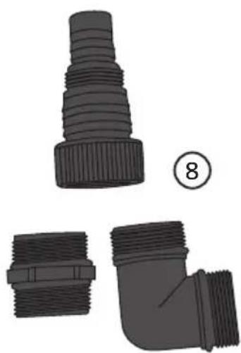
Universal hose union 38 mm and 25 mm + 1" and 1¼" male thread
- 90° elbow, 1¼" male thread
- Straight hose connector, 1¼" male thread
natural_image
Illustration of three different pipe fitting components: a conical threaded connector, a threaded pipe fitting, and an L-shaped pipe fitting (no text or symbols present)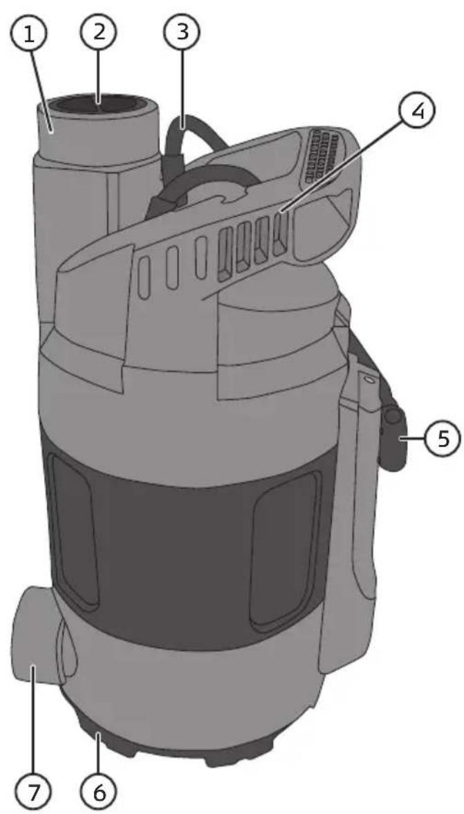
Before use
Pressure hose connection
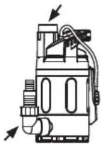
Fit the included universal hose union onto one of the outlets (1 or 7) ^* .
Note: The plastic plug (2) should be inserted into the outlet which is not being used.
natural_image
Technical line drawing of a mechanical device with no visible text or symbols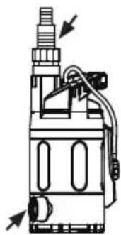
natural_image
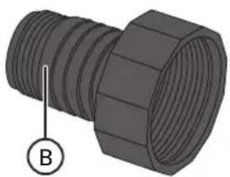
Technical line drawing of a mechanical device with no visible text or symbolsThe universal hose union is fitted with a 38 mm (1½") and 25 mm (1") diameter barbed hose connectors and a 1" male threaded hose connector. 38 mm hoses provide the best capacity.
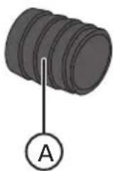
If the 38 mm barbed hose connector or the 1" threaded connector are to be used, the end of the nipple (A) should be cut off as shown in the figure. Cut off the part of the universal hose union (B) that is not needed (if using large diameter hose).
natural_image
3D rendering of a threaded pipe fitting with a labeled section B (no text or symbols on the object itself)* The pump has two alternative outlets, upper (1) and lower (7). Depending on the construction of the pump the upper outlet (1) provides about 10% less water flow than the lower outlet (7).
Note: The plastic plug (2) must be inserted into the outlet which is not used.
Positioning and transportation
- The pump should be placed in a stable position.
- The inlet must not be blocked in any way. Make sure that there are no loose particles such as sand or stones near the inlet as this increases wear on the pump and could even cause a stoppage.
- Do not use the mains lead to lift or carry the pump. Always use a rope tied to the handle when lowering or raising the pump.
Operating instructions
The pump is fitted with an electronic level sensor which detects the water level and automatically starts and stops the pump.
Operation
When the pump is connected to the mains it will run for about 10 seconds and if the sensor is above the level of the water the pump will stop after these 10 seconds, but if the sensor is below the water level the pump will continue for as long as the sensor is below the water level.
The pump starts: when the water level rises over the sensor, the pump starts after about 2 seconds and continues for as long as the sensor is under water.
The pump stops: when the water level drops below the sensor, the pump stops after about 10 seconds.
Adjusting the pump stop/start level
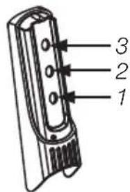
The pump has three holes in which the sensor can be placed to select the stop/start level.
Care and maintenance
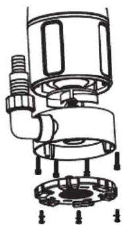
If necessary, unplug the mains lead from the wall socket, remove the 3 screws holding the cover plate onto the base of the pump, then remove the 4 screws holding the impeller housing and clean the inlet (6) of any debris.
Screw the parts back on in reverse order, making sure that the outlet on the impeller housing is on the same side of the pump as the upper outlet.
natural_image
Technical line drawing of a mechanical valve assembly (no text or symbols)Troubleshooting guide
| Problem Possible cause Possible solution | ||
| The pump does not start. | 1. The pump is not plugged in.2. The water level is below the sensor.3. The impeller is blocked by something such as a stone. | 1. Make sure the pump is plugged into a live socket, check the fuse/circuit breaker.2. The pump starts automatically when the water level rises.3. Dismantle the impeller housing and clean it as described in Care and maintenance. |
| The pump does not pump. | 1. Air leakage on the suction side.2. The impeller housing is blocked.3. The pressure hose is blocked. | 1. Wait for up to 1 minute for the pump to automatically be purged of air. Unplug the pump and then plug it in again to restart the pump.2. Unplug the pump from the power supply and remove any debris from the water inlet.3. Clean the hose, straighten out any kinks, etc. |
| The pump doesn’t stop when water level has fallen. | Check that the pump is upright or if it has fallen on its side so the sensor is on the bottom. | Check the water level, if it is above the sensor, the pump will not stop. |
| The flow is too low. | 1. The inlet filter is clogged.2. The pump could have deposits inside the impeller housing. | 1. Unplug the pump from the power supply and remove any debris from the inlet filter.2. Unplug the pump from the power supply and remove any deposits from the impeller housing. Refer to the Care and maintenance section. |
| The pump stops after a short while. | 1. The overheating protection has tripped because the motor became too hot.2. The sensor has stopped the motor because the pump is blocked. | 1. Remember that the max liquid temperature is 35 °C.2. Check and clean the impeller housing as described in Care and maintenance. |
Disposal
Dispose of your waste responsibly, sort and recycle where possible. All machines, hoses and packing material should be sorted and handled according to local environmental regulations.
Specifications
Model LKS-404PS
Wattage 400 W
Rated voltage 230 V AC, 50 Hz
Pump capacity 150 l/min
Pressure head 7 m
Max submersible depth 7 m
Max particle size 5 mm
Max water temperature 35 °C
Hose connection 25 mm and 38 mm
Union thread
1¼" (female) × 2
Length of mains lead 10 m (H05RN-F)
Ingress protection: IPX8
Weight 3.8 kg
Dränkbar pump rostfri
natural_image
Illustration of three different types of pipe fittings: a conical, threaded pipe fitting, a threaded pipe fitting, and an L-shaped pipe fitting (no text or symbols present)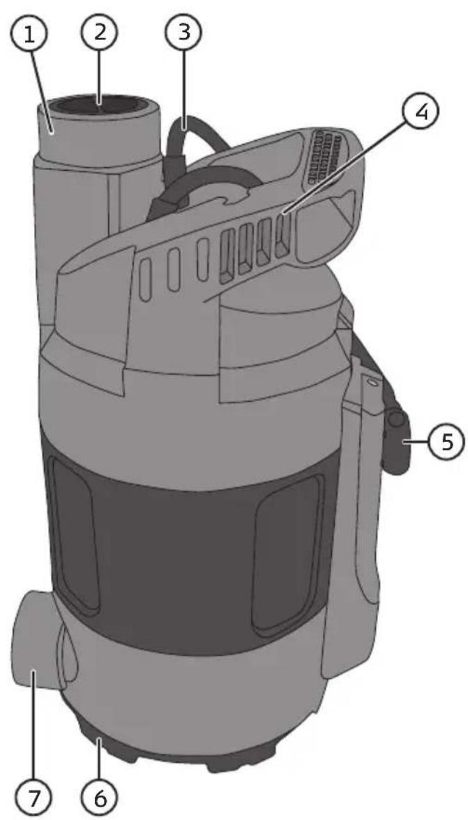
natural_image
Technical line drawing of a mechanical device with no visible text or symbols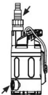
natural_image
Technical line drawing of a mechanical device with no visible text or symbolsnatural_image
3D rendering of a threaded pipe fitting with a labeled section B (no text or symbols on the object itself)natural_image
Technical line drawing of a mechanical device with no visible text or symbolsFelsökningsschema
natural_image
Illustration of three different pipe fitting components: a conical threaded connector, a threaded pipe fitting with flange, and a bent pipe fitting (no text or symbols present)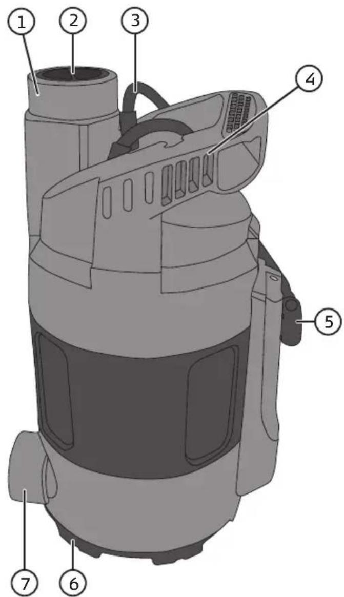
Før bruk
natural_image
Technical line drawing of two mechanical device components with directional arrows indicating movement (no text or symbols)En slange med diameter 38 mm (1 ½") eller 25 mm (1") eller med utvendige gjenger på 1" kan kobles til universaltilkoblingen. Slange med diameter på 38 mm gir den beste kapasiteten.
Hvis det benyttes en 38 mm slangetilkobling eller en 1" gjengetilkobling skal nippelen (A) kappes som vist på bildet.
natural_image
Two technical illustrations of a threaded connector, labeled A and B, showing internal threading (no text or symbols beyond labels)natural_image
Technical line drawing of a mechanical valve assembly (no text or symbols)Feilsøking
natural_image
Illustration of three different pipe fitting components (tens, side, and right-angle) with no text or symbols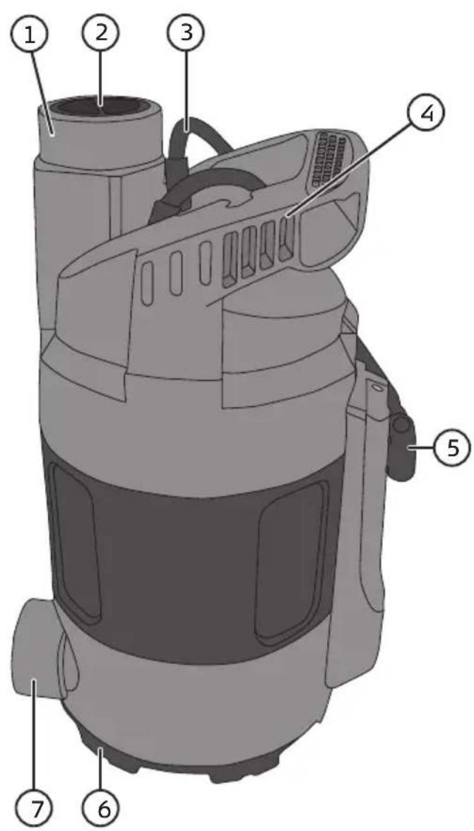
natural_image
Technical line drawing of a mechanical valve assembly (no text or symbols)Vianhakutaulukko
natural_image
Illustration of three different pipe fitting components: a conical plug, a threaded pipe fitting, and an L-shaped pipe fitting (no text or symbols present)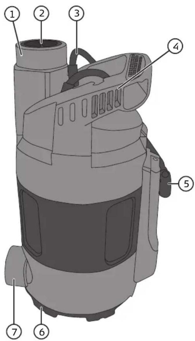
natural_image
Technical line drawing of two mechanical components with directional arrows indicating movement or force (no text or symbols)natural_image
Two 3D mechanical connectors labeled A and B, showing threaded and threaded surfaces (no text or symbols beyond labels)natural_image
Technical line drawing of a mechanical valve assembly (no text or symbols)Fehlersuche
Declaration of Conformity
Declares that this product complies with the requirements of the following directives and standards
Postal 10 - 13 Market Place
Kingston Upon Thames
Surrey
KT1 1JZ
Deutschland
Kundenservice
- Viktig information:
- Stainless Steel Submersible Pump
- Safety
- Product description
- Before use
- Pressure hose connection
- Positioning and transportation
- Operating instructions
- Operation
- Adjusting the pump stop/start level
- Care and maintenance
- Troubleshooting guide
- Disposal
- Specifications
- Dränkbar pump rostfri
- Før bruk
- Vianhakutaulukko
- Fehlersuche
- Declaration of Conformity
- Deutschland
Brand : Cocraft
Model : HS 400-DE
Category : Water pump