
XB-14² - Blender ALLEN & HEATH - Free user manual and instructions
Find the device manual for free XB-14² ALLEN & HEATH in PDF.


| Product Type | Professional Broadcast Mixer |
| Brand & Model | Allen & Heath XB-14 MK2 |
| Weight | 7.5 kg (unpacked), 11.5 kg (packed) |
| Power Supply | Mains powered via detachable IEC cord |
| Input Channels | 4 mono mic/line, 2 telco, 4 stereo (2 with dual RCA/Jack, 2 with RCA/Jack) |
| Outputs | Main PGM XLR (L/R), Mono RCA, Mix B RCA, Audition RCA, Aux Jack, CRM Speakers RCA, Telco Clean-Feed XLR |
| Headphone Outputs | 3 (1 engineer, 2 guest) with independent source selection |
| EQ | 3-band on mono channels (HF, MF sweep, LF); Telco: HPF & LPF; Stereo: HF & LF tone controls |
| USB Audio | Stereo bidirectional USB 1.1/2.0 compliant, selectable routing |
| Phantom Power | +48V switchable to all 4 mic XLR inputs |
| Remote Control | Mono fader start logic, stereo start/cue outputs, external mute inputs (D-sub connectors) |
| Monitoring | CRM speakers + headphone sources with priority matrix; PFL on each channel |
| Special Buses | Audition bus, Mix B bus, Aux bus (pre/post switch) |
| Construction | Individual vertical channel PCBs, metal nut mounted rotary controls, 100mm faders |
| Safety Compliance | EN55103, EN60065, CE marked |
| Warranty | 1 year limited (excluding fader wear) |
Frequently Asked Questions - XB-14² ALLEN & HEATH
User questions about XB-14² ALLEN & HEATH
0 question about this device. Answer the ones you know or ask your own.
Ask a new question about this device
Download the instructions for your Blender in PDF format for free! Find your manual XB-14² - ALLEN & HEATH and take your electronic device back in hand. On this page are published all the documents necessary for the use of your device. XB-14² by ALLEN & HEATH.
USER MANUAL XB-14² ALLEN & HEATH
natural_image
3D rendering of a black audio mixing console with multiple knobs and control knobs (no visible text or labels)
USER GUIDE
Publication AP8769
Limited One Year Warranty
This product is warranted to be free from defects in materials or workmanship for period of one year from the date of purchase by the original owner.
To ensure a high level of performance and reliability for which this equipment has been designed and manufactured, read this User Guide before operating. In the event of a failure, notify and return the defective unit to ALLEN & HEATH Limited or its authorised agent as soon as possible for repair under warranty subject to the following conditions
Conditions Of Warranty
The equipment has been installed and operated in accordance with the instructions in this User Guide.
The equipment has not been subject to misuse either intended or accidental, neglect, or alteration other than as described in the User Guide or Service Manual, or approved by ALLEN & HEATH.
Any necessary adjustment, alteration or repair has been carried out by ALLEN & HEATH or its authorised agent.
This warranty does not cover fader wear and tear.
The defective unit is to be returned carriage prepaid to ALLEN & HEATH or its authorised agent with proof of purchase.
Units returned should be packed to avoid transit damage.
In certain territories the terms may vary. Check with your ALLEN & HEATH agent for any additional warranty which may apply.

This product complies with the European Electromagnetic Compatibility directive 2004/108/EC and the European Low Voltage directive 2006/95/EC.
This product has been tested to EN55103 Parts 1 & 2 2009 for use in Environments E1, E2, E3, and E4 to demonstrate compliance with the protection requirements in the European EMC directive 2004/108/EC. During some tests the specified performance figures of the product were affected. This is considered permissible and the product has been passed as acceptable for its intended use. Allen & Heath has a strict policy of ensuring all products are tested to the latest safety and EMC standards. Customers requiring more information about EMC and safety issues can contact Allen & Heath.
NOTE: Any changes or modifications to the console not approved by Allen & Heath could void the compliance of the console and therefore the users authority to operate it.
Allen & Heath XB-14 MK2 User Guide AP8769 Issue 2
Copyright © 2012 Allen & Heath Limited. All rights reserved
Allen & Heath Limited
Kernick Industrial Estate, Penryn, Cornwall, TR10 9LU, UK
http://www.allen-heath.com
PACKED ITEMS
Check that you have received the following:
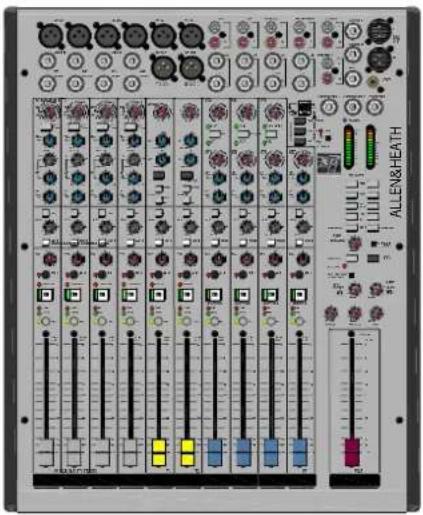
XB-14 MK2 MIXER

natural_image
Simple line drawing of a cable with two connectors (no text or symbols)Mains Lead (or leads)
Check that the correct mains plug is fitted.
This User Guide
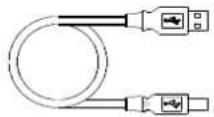
Type A-B USB Lead
To connect the XB-14 to your computer.
SAFETY INSTRUCTIONS
WARNINGS - Read the following before proceeding :
ATTENTION: RISQUE DE CHOC ELECTRIQUE – NE PAS OUVRIR
Read instructions: Retain these safety and operating instructions for future reference. Adhere to all warnings printed here and on the console. Follow the operating instructions printed in this User Guide.
Do not remove cover: Operate the console with its covers correctly fitted.
Power sources: Connect the console to a mains power unit only of the type described in this User Guide and marked on the rear panel. Use the power cord with sealed mains plug appropriate for your local mains supply as provided with the console. If the provided plug does not fit into your outlet consult your service agent for assistance.
Power cord routing: Route the power cord so that it is not likely to be walked on, stretched or pinched by items placed upon or against it.
Grounding: Do not defeat the grounding and polarisation means of the power cord plug. Do not remove or tamper with the ground connection in the power cord.

WARNING: This equipment must be earthed.
Water and moisture: To reduce the risk of fire or electric shock do not expose the console to rain or moisture or use it in damp or wet conditions. Do not place containers of liquids on it which might spill into any openings.
Ventilation: Do not obstruct the ventilation slots or position the console where the air flow required for ventilation is impeded. If the console is to be operated in a rack unit or flightcase ensure that it is constructed to allow adequate ventilation.
Heat and vibration: Do not locate the console in a place subject to excessive heat or direct sunlight as this could be a fire hazard. Locate the console away from any equipment which produces heat or causes excessive vibration.
Servicing: Switch off the equipment and unplug the power cord immediately if it is exposed to moisture, spilled liquid, objects fallen into the openings, the power cord or plug become damaged, during lightening storms, or if smoke, odour or noise is noticed. Refer servicing to qualified technical personnel only.
Installation: Install the console in accordance with the instructions printed in this User Guide. Do not connect the output of power amplifiers directly to the console. Use audio connectors and plugs only for their intended purpose.
SAFETY INSTRUCTIONS
Important Mains plug wiring instructions
The console is supplied with a moulded mains plug fitted to the AC mains power lead. Follow the instructions below if the mains plug has to be replaced. The wires in the mains lead are coloured in accordance with the following code:

The wire which is coloured Green and Yellow must be connected to the terminal in the plug which is marked with the letter E or with the Earth symbol. This appliance must be earthed.
The wire which is coloured Blue must be connected to the terminal in the plug which is marked with the letter N.
The wire which is coloured Brown must be connected to the terminal in the plug which is marked with the letter L.
Ensure that these colour codes are followed carefully in the event of the plug being changed.
General Precautions:
Damage :
To prevent damage to the controls and cosmetics avoid placing heavy objects on the control surface, scratching the surface with sharp objects, or rough handling and vibration.
Environment :
Protect from excessive dirt, dust, heat and vibration when operating and storing. Avoid tobacco ash, smoke, drinks spillage, and exposure to rain and moisture. If the console becomes wet, switch off and remove mains power immediately. Allow to dry out thoroughly before using again.
Cleaning :
Avoid the use of chemicals, abrasives or solvents. The control panel is best cleaned with a soft brush and dry lint-free cloth. The faders, switches and potentiometers are lubricated for life. The use of electrical lubricants on these parts is not recommended. The fader and potentiometer knobs may be removed for cleaning with a warm soapy solution. Rinse and allow to dry fully before refitting them.
Transporting :
The console may be transported as a free-standing unit or mounted in a rack or flightcase. Protect the controls from damage during transit. Use adequate packing if you need to ship the unit.
Hearing :

To avoid damage to your hearing do not operate any sound system at excessively high volume. This applies particularly to close-to-ear monitoring such as headphones and in-ear systems. Continued exposure to high volume sound can cause frequency selective or wide range hearing loss.
CONTENTS
Thank you for purchasing your Allen & Heath XB-14 mixer. To ensure that you get the maximum benefit from the unit please spare a few minutes familiarizing yourself with the controls and setup procedures outlined in this user guide. For further information please refer to the additional information available on our web site, or contact our technical support team.
http://www.allen-heath.com
http://www.allen-heath.com/xb
Warranty 3
Packed Items 4
Safety Instructions 5
Contents......7
Panel Drawings 8
Introduction to XB-14 9
Specifications 11
Dimensions 13
Block Diagram 14
Mono Input Channel 15
TELCO Channels 1&2 18
Stereo Input Channel ST1 & ST2 ....21
Stereo Input Channels ST3 & ST4 .. 23
Master Section 24
Remote Interface connectors ...... 27
On Switch Options 28
Remote Interface wiring 29
USB Connecting to a Computer .... 30
Application Diagram—Self Op ...... 31
Application Diagram—Studio ...... 32
Tips-off-air recording 33
Fixing into a Rack or furniture ..... 34
General wiring notes 35
Product Support 36
Service Options 37
PANEL DRAWINGS
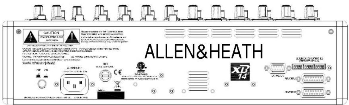
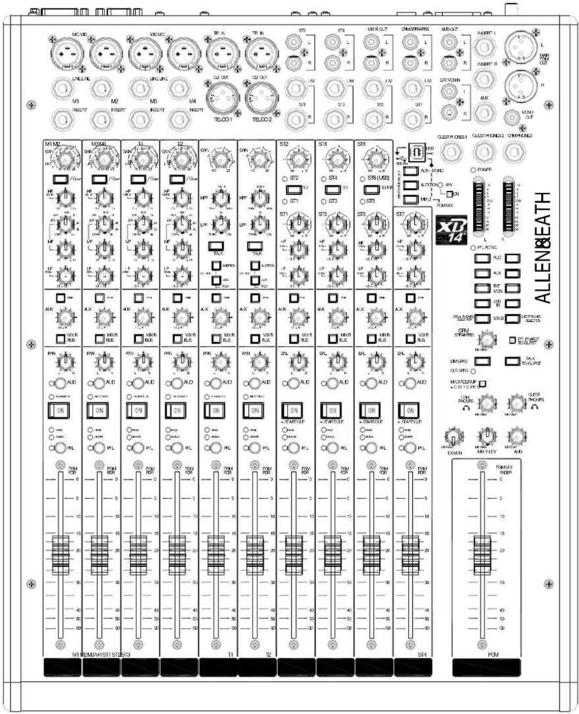
INTRODUCTION TO THEXB-14
Background overview:
The Allen & Heath XB-14 mixer has been carefully and lovingly designed in the beautiful county of Cornwall in the UK and is manufactured alongside a wide range of professional audio mixing consoles. Many of the components used in the XB-14 are exactly the same as in the larger Allen & Heath products and the construction methods are also very similar utilising individual vertically mounted channel circuit boards with each rotary control fixed with a metal nut to the front panel. This provides a very robust product that will resist damage and give years of reliable use. It also makes servicing much easier should it be required, with the ability to remove one particular channel from the mixer at a time, or easily change a fader.
The audio circuitry is based on years of continual development and refinement, the performance of all the elements within the mixer scrutinised and perfected to ensure the very best sound quality possible.
Multi-application:
The XB-14 is great for a range of applications from small radio or internet broadcast studios, or for larger studios with multiple rooms, for hospital radio, university radio and community radio broadcast applications. The XB-14 has a wealth of features specifically designed for broadcasters, things like telephone communication modules for telephone callers, mic fader start sensing for external connection and internal automatic muting of the speaker outputs, stereo channel start/cue outputs for CD deck transport control, separate headphones mix & outputs for guests, an audition bus.... The list goes on!
Mic/Line Pre-amps:
The XB-14 pre-amps use a two stage design, with carefully controlled amounts of gain in each stage. When amplifying the signal from the XLR input, the gain range is huge (69dB of range to be exact) and is very evenly distributed around the gain control, meaning better control of signal level. Most of the gain comes from the first stage, so unwanted noise is kept to a minimum. There is no “pad” switch, or pad circuit — line level signals are simply plugged into the second stage of the pre-amp by using the line input jack socket. This has the great advantage of lower noise when using the line input. (It is common to attenuate line level signals, then amplify them back up again which can give more noise or hiss).
EQ:
The XB-14 is equipped with a 3-band equaliser circuit on each mono input which can be used to cut sibilance or mic popping or to change the tone of a presenters voice. The telco channels are fitted with a total cut high pass and low pass filter which can be used to eliminate the top or bottom end of the channel frequency response. This can be very useful when a caller is connected via a low quality telephone line. Stereo channels have high and low frequency tone controls for use with music.
AUX bus:
XB-14 has a single Auxiliary bus that can be used for external processing, effects, recording or auditioning.
MIX B:
A separate stereo mix bus is provided for recording an independent mix to the main program mix, or creating a clean feed source with selected channels.
Audition bus:
The XB-14 has a dedicated stereo audition bus that can be used for auditioning or off air recording. Pressing the button marked AUD on the channels required, transfers the mix from the program feed over to the audition bus.
Channel signal/peak indicators:
Each channel on the XB-14 has an indicator to show if there is signal present. This is pre fader / ON switch so the operator can be aware of channels that are active. The peak LED also gives a warning if a channel is in danger of exceeding its peak level.
Remote Control:
The mono mic/line channels have fader start logic switching enabling them to control external equipment or automatically mute the speaker outputs to prevent acoustic feedback in localised or self-operated applications. The stereo channels have start & cue logic outputs available to hook up to external equipment like CD players. There are also options to mute the mono inputs remotely using an external "cough" switch or similar.
INTRODUCTION TO THEXB-14
USB:
Getting audio to and from a computer easily is now a common requirement for sound and music production and broadcast applications. The way we have implemented this on XB-14 is super-flexible and super-easy! No longer do you need to fiddle around the back of your computer to get to the soundcard inputs, only to find that the levels are all wrong and noisy. Just plug in a USB lead to your XB-14, select the USB routing on the mixer and the device on your computer and that's it! Quality audio to and from your PC or MAC.
Guest headphones:
The XB-14 has 3 headphone outputs. There is a headphones socket for the presenter/engineer with a routing matrix. There are two guest headphone outputs with a separate routing matrix. There is also a talk button for off air conversation with guests via the user selected comms mic channel.
Output matrix:
Both the operator and guest headphone outputs (and the control room speakers) have an output matrix with priority switched feeds. This means the operator could be monitoring one bus while a guest is listening to the program mix. There are many possible combinations.
Electronically balanced outputs:
The main program outputs are on XLR connectors with an electronically balanced output circuit.
Self operation or Producer operated:
Whether you need a mixer for a self operated broadcast situation, or whether you have a separate studio and engineer, the XB-14 has the features to fit. Separate monitor mixes can be created for operator and guests or presenter so the engineer can check levels and cue sources while the presenter or guest can listen to a different source. The engineer/producer can communicate to the guest or presenter using the Talk feature, as well as off-air communication to telephone callers.
There is also the facility for remote control of channel mutes from the studio using the remote interface connectors, ideal for studio situated mute switches.
SPECIFICATIONS
| Operating Levels | |
| Input | |
| Mono channel Mic input (XLR) +6 to -63dBu for nominal (+17dBu in max) | |
| Mono channel Line input (TRS Jack socket) +10 to -26dBu (+30dBu maximum) | |
| Insert point (TRS Jack socket) 0dBu nominal +21dBu maximum | |
| Stereo input (TRS Jack sockets) 0dBu nominal (control = Off to +10dB) | |
| Stereo input (RCA phono sockets) 0dBu nominal (control = Off to +10dB) | |
| Telco channel input (XLR) +10 to -26dBu (+30dBu maximum) | |
| External monitor inputs (RCA phono sockets) 0dBu Nominal | |
| Output | |
| PGM L & R outputs (XLR) +4dBu nominal. +25dBu maximum. | |
| PGM Mono output (RCA phono) 0dBu nominal. +21dBu maximum. | |
| PGM L & R inserts (TRS jack sockets) -2dBu nominal. +21dBu maximum | |
| Aux output (Jack socket) 0dBu nominal. +21dBu maximum. | |
| Mix B outputs (RCA phono sockets) 0dBu nominal. +21dBu maximum. | |
| Audition outputs (RCA phono sockets) | 0dBu nominal. +21dBu maximum. |
| Telco output (XLR) | 0dBu nominal. +21dBu maximum. |
| CRM Speaker outputs (RCA phono sockets) | 0dBu nominal. +21dBu maximum. |
| THD+n | |
| Mic in to PGM L/R Out, 0dB gain, 1kHz, +10dBu out | <0.01% |
| Mic in to PGM Out, 30dB gain, 1kHz, +10dBu out <0.01% | |
| Line in to PGM L/R out 0dB gain, 1kHz, 0dBu out | <0.01% |
| Stereo in to PGM out 0dB gain, 1kHz, +10dBu out | <0.01% |
| USB Audio CODEC (Coder/Decoder) | |
| USB Audio In/Out | USB 1.1 compliant 16bit. |
| Sample Rate | 32, 44.1, or 48kHz |
| Noise | |
| Mic Pre EIN @ max gain 150R input Z 22-22kHz -124dBu | |
| PGM out, PGM fader = 0, 22-22kHz | <-100dBu |
| Audition out, Mix B out = 0, 22-22kHz | <-100dBu |
| Aux out, Mono out = 0, 22-22kHz | <-85dBu |
SPECIFICATIONS
| Headroom | |
| Analogue Headroom from nominal (0Vu) Outputs 21dB | |
| Analogue Headroom from nominal (0Vu) Mix point 24dB | |
| USB in & out headroom from nominal (0Vu) 14dB | |
| Crosstalk & Attenuation (dB 22-22kHz) | |
| Mono fader attenuation (dB relative to +10dBu) 1kHz/10kHz -95/-95 | |
| Mono ON switch attenuation (dB relative to +10dBu) 1kHz/10kHz -95/-95 | |
| TELCO fader attenuation (dB relative to +10dBu) 1kHz/10kHz -95/-95 | |
| TELCO ON switch attenuation (dB relative to +10dBu) 1kHz/10kHz -95/-95 | |
| Stereo fader attenuation (dB relative to +10dBu) 1kHz/10kHz -95/-90 | |
| Stereo ON switch attenuation (dB relative to +10dBu) 1kHz/10kHz -95/-95 | |
| PGM fader attenuation (dB relative to +10dBu) 1kHz/10kHz -100/-95 | |
| TELCO clean-feed isolation from I/P (dB relative to +10dBu) 1kHz/10kHz | -55/-40 |
| Stereo separation, L in to PGM R out. dBr 1kHz/10kHz | -70/-50 |
| Frequency Response | |
| Mic in to PGM L/R Out, 30dB gain +0.5/-1dB 10Hz to 30kHz. | |
| Line in to PGM L/R out 0dB gain +0.5/-1dB 10Hz to 30kHz | |
| Stereo in to PGM L/R out +0.5/-1dB 10Hz to 30kHz | |
Dimensions
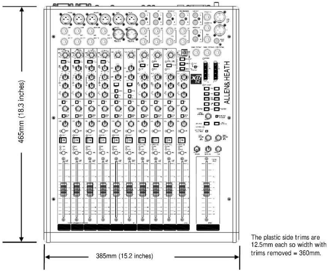
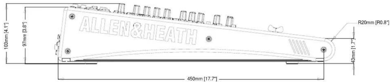
| W eight | |
| XB-14 | |
| Unpacked | 7.5kg |
| Packed 11.5kg (25.3lb) | |
(16.5lb
A rack mounting kit is available for XB-14. The part number is: ZED1402-RK19
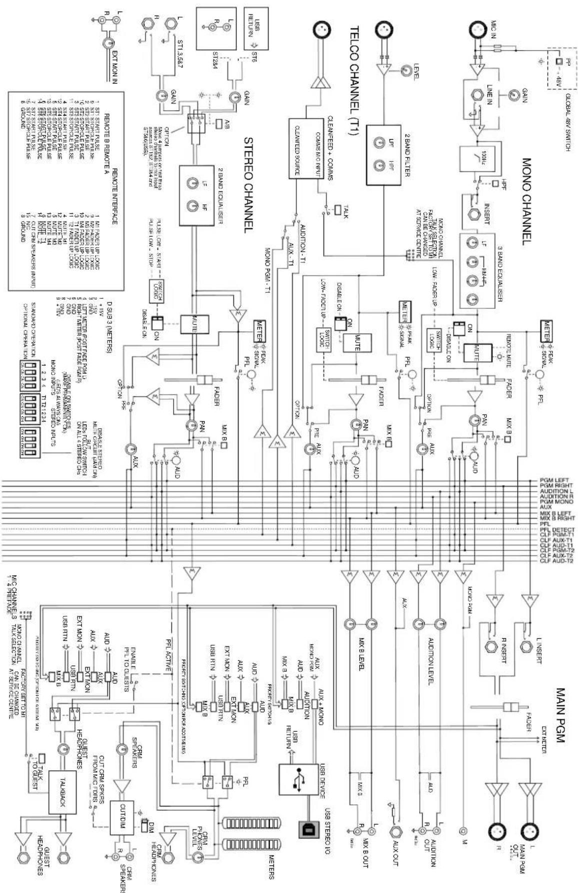
flowchart
graph TD
    subgraph MAIN_PGM
        A["MAIN PGM"] --> B["OUTRUN"]
        B --> C["OUTRUNS"]
        C --> D["OUTRUNS"]
        D --> E["OUTRUNS"]
        E --> F["OUTRUNS"]
        F --> G["OUTRUNS"]
        G --> H["OUTRUNS"]
        H --> I["OUTRUNS"]
        I --> J["OUTRUNS"]
        J --> K["OUTRUNS"]
        K --> L["OUTRUNS"]
        L --> M["OUTRUNS"]
        M --> N["OUTRUNS"]
        N --> O["OUTRUNS"]
        O --> P["OUTRUNS"]
        P --> Q["OUTRUNS"]
        Q --> R["OUTRUNS"]
        R --> S["OUTRUNS"]
        S --> T["OUTRUNS"]
        T --> U["OUTRUNS"]
        U --> V["OUTRUNS"]
        V --> W["OUTRUNS"]
        W --> X["OUTRUNS"]
        X --> Y["OUTRUNS"]
        Y --> Z["OUTRUNS"]
        Z --> AA["OUTRUNS"]
        AA --> AB["OUTRUNS"]
        AB --> AC["OUTRUNS"]
        AC --> AD["OUTRUNS"]
        AD --> AE["OUTRUNS"]
        AE --> AF["OUTRUNS"]
        AF --> AG["OUTRUNS"]
        AG --> AH["OUTRUNS"]
        AH --> AI["OUTRUNS"]
        AI --> AJ["OUTRUNS"]
        AJ --> AK["OUTRUNS"]
        AK --> AL["OUTRUNS"]
        AL --> AM["OUTRUNS"]
        AM --> AN["OUTRUNS"]
        AN --> AO["OUTRUNS"]
        AO --> AP["OUTRUNS"]
        AP --> AQ["OUTRUNS"]
        AQ --> AR["OUTRUNS"]
        AR --> AS["OUTRUNS"]
        AS --> AT["OUTRUNS"]
        AT --> AU["OUTRUNS"]
        AU --> AV["OUTRUNS"]
        AV --> AW["OUTRUNS"]
        AW --> AX["OUTRUNS"]
        AX --> AY["OUTRUNS"]
        AY --> AZ["OUTRUNS"]
        AZ --> BA["OUTRUNS"]
        BA --> BB["OUTRUNS"]
        BB --> BC["OUTRUNS"]
        BC --> BD["OUTRUNS"]
        BD --> BE["OUTRUNS"]
        BE --> BF["OUTRUNS"]
        BF --> BG["OUTRUNS"]
        BG --> BH["OUTRUNS"]
        BH --> BI["OUTRUNS"]
        BI --> BJ["OUTRUNS"]
        BJ --> BK["OUTRUNS"]
        BK --> BL["OUTRUNS"]
        BL --> BM["OUTRUNS"]
        BM --> BN["OUTRUNS"]
        BN --> BO["OUTRUNS"]
        BO --> BP["OUTRUNS"]
        BP --> BQ["OUTRUNS"]
        BQ --> BR["OUTRUNS"]
        BR --> BS["OUTRUNS"]
        BS --> BT["OUTRUNS"]
        BT --> BU["OUTRUNS"]
        BU --> BV["OUTRUNS"]
        BV --> BW["OUTRUNS"]
        BW --> BX["OUTRUNS"]
        BX --> BY["OUTRUNS"]
        BY --> BZ["OUTRUNS"]
        BZ --> CA["OUTRUNS"]
        CA --> CB["OUTRUNS"]
        CB --> CC["OUTRUNS"]
        CC --> CD["OUTRUNS"]
        CD --> CE["OUTRUNS"]
        CE --> CF["OUTRUNS"]
        CF --> CG["OUTRUNS"]
        CG --> CH["OUTRUNS"]
        CH --> CI["OUTRUNS"]
        CI --> CJ["OUTRUNS"]
        CJ --> CK["OUTRUNS"]
        CK --> CL["OUTRUNS"]
        CL --> CM["OUTRUNS"]
        CM --> CN["OUTRUNS"]
        CN --> CO["OUTRUNS"]
        CO --> CP["OUTRUNS"]
        CP --> CQ["OUTRUNS"]
        CQ --> CR["OUTRUNS"]
        CR --> CS["OUTRUNS"]
        CS --> CT["OUTRUNS"]
        CT --> CU["OUTRUNS"]
        CU --> CV["OUTRUNS"]
        CV --> CW["OUTRUNS"]
        CW --> CX["OUTRUNS"]
        CX --> CY["OUTRUNS"]
        CY --> CZ["OUTRUNS"]
        CZ --> DA["OUTRUNS"]
        DA --> DB["OUTRUNS"]
        DB --> DC["OUTRUNS"]
        DC --> DD["OUTRUNS"]
        DD --> DE["OUTRUNS"]
        DE --> DF["OUTRUNS"]
        DF --> DG["OUTRUNS"]
        DG --> DH["OUTRUNS"]
        DH --> DI["OUTRUNS"]
        DI --> DJ["OUTRUNS"]
        DJ --> DK["OUTRUNS"]
        DK --> DL["OUTRUNS"]
        DL --> DV["OUTRUNS"]
        DV --> DW["OUTRUNS"]
        DW --> DXD[D OUT RUN SISTOS 100% OFF/ON 50% OFF/ON 50% OFF/ON 50% OFF/ON 50% OFF/ON 50% OFF/ON 50% OFF/ON 50% OFF/ON 50% OFF/ON 50% OFF/ON 50% OFF/ON 50% OFF/ON 50% OFF/ON 50% OFF/ON 50% OFF/ON 50%
    end

    subgraph STEREO_CHANNEL
            C
            D
            E
            F
            G
            H
            I
            J
            K
            L
            M
            N
            O
            P
            Q
            R
            S
            T
            U
            V
            W
            X
            Y
            Z
            AA
            AB
            AC
            AD
            AE
            AF
            AG
            AH
            AI
            AJ
            AK
            AL
            AM
            AN
            AO
            AP
            AQ
            AR
            AS
            AT
            AU
            AV
            AW
            AX
            AY
            AZ
            BA
            BA
            BA
            BA
            BA
            BA
            BA
            BA
            BA
            BA
            BA
            BA
            BA
            BA
            BA
            BA
            BA
            BA
            BA
            BA
            BA
            BA
            BA
            BA
            BA
            BA
            BA
            BA
            BA
            BA
            BA
            BA
            BA
            BA
XB-14 MK2 BLOCK DIAGRAM
MONO INPUT CHANNEL
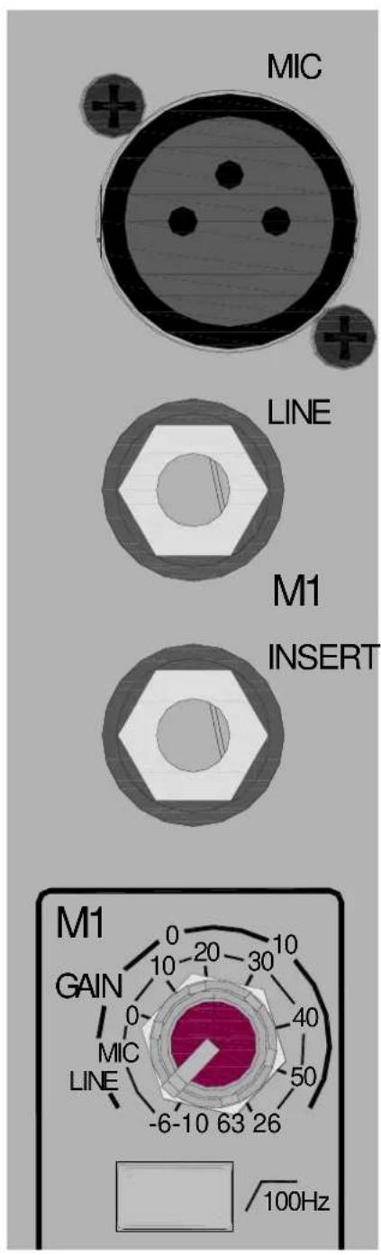
Mic Input Socket
Standard 3-Pin XLR socket wired as Pin 1=Chassis, Pin 2=hot (+), Pin 3=Cold (-).
Line Input Jack Socket
Standard 1/4" (6.25mm) Jack socket for balanced or unbalanced line level signals. Wired Tip=Hot (+), Ring=cold (-), Sleeve=Chassis. The Line input overrides the Mic input, so if you want to hear something plugged in to the xlr socket, make sure nothing is plugged into the Line input.
Insert Jack Socket
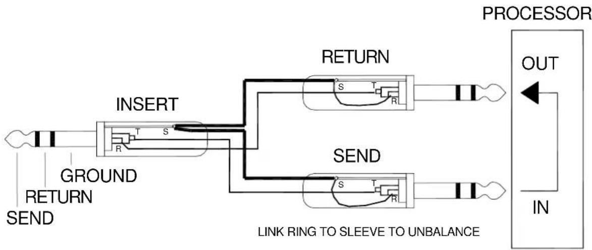
Standard 1/4" (6.25mm) Jack socket for unbalanced insert send and return signals. Wired Tip=send, Ring=return, Sleeve=Chassis. Nominal level is 0dBu. The insert point is after the 100Hz filter and before the EQ.
Gain Control
This adjusts the gain of the input amplifier to match the signal level of the input. The gain is varied from -6dB (attenuation) to +63dB for signals plugged in to the xlr socket (Mic Input) and -10dB to +26dB for signals plugged into the Line input jack.
line
| Time | Value | | -------- | ------ | | 10:00 | -70.00 | | 11:00 | -30.00 | | 12:00 | -10.00 | | 13:00 | 0.00 | | 14:00 | 2.69 | | 15:00 | 2.69 | | 16:00 | 2.69 | | 17:00 | 2.69 | | 18:00 | 2.69 | | 19:00 | 2.69 | | 20:00 | 2.69 | | 21:00 | 2.69 | | 22:00 | 2.69 | | 23:00 | 2.69 | | 24:00 | 2.69 |100Hz High Pass Filter
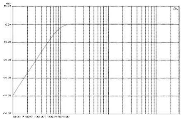
The Hi-pass filter is used for reducing pop noise and rumble from microphone signals. It is a 2-pole (12dB per octave) filter with a corner frequency set at 100Hz. The filter affects signals from both Mic XLR and Line jack socket.
MONO INPUT CHANNEL
HFEQ
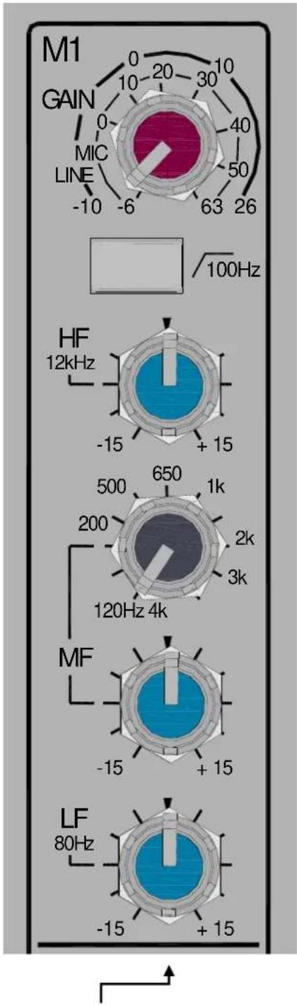
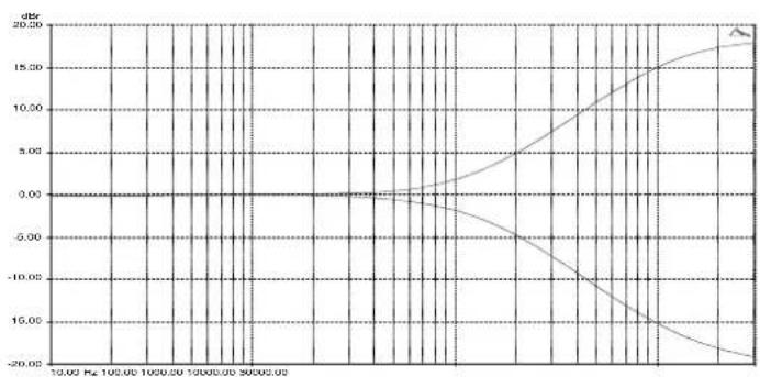
The HF (High Frequency) equaliser affects the frequency response of the higher audible frequencies. The corner frequency of 12kHz is around 3dB from the maximum cut or boost of the circuit. It has plenty of gain and actually gives slightly more that the +/-15dB legend suggests.
line
| x | y | | ------ | ----- | | 10.00 Hz | 0.0 | | 100.00 Hz | 0.0 | | 1020.00 Hz | 0.0 | | 1040.00 Hz | 0.0 | | 1060.00 Hz | 0.0 | | 1080.00 Hz | 0.0 | | 1100.00 Hz | 0.0 | | 1120.00 Hz | 0.0 | | 1140.00 Hz | 0.0 | | 1160.00 Hz | 0.0 | | 1180.00 Hz | 0.0 | | 1200.00 Hz | 0.0 | | 1220.00 Hz | 0.0 | | 1240.00 Hz | 0.0 | | 1260.00 Hz | 0.0 | | 1280.00 Hz | 0.0 | | 1300.00 Hz | 0.0 | | 1320.00 Hz | 0.0 | | 1340.00 Hz | 0.0 | | 1360.00 Hz | 0.0 | | 1380.00 Hz | 0.0 | | 1400.00 Hz | 0.0 | | 1420.00 Hz | 5.5 | | 1440.00 Hz | 7.5 | | 1460.00 Hz | 9.5 | | 1480.00 Hz | 11.5 | | 1500.00 Hz | 13.5 | | 1520.00 Hz | 15.5 | | 1540.00 Hz | 17.5 | | 1560.00 Hz | 19.5 | | 1580.00 Hz | 21.5 | | 1600.00 Hz | 23.5 | | 1620.00 Hz | 25.5 | | 1640.00 Hz | 27.5 | | 1660.00 Hz | 29.5 | | 1680.00 Hz | 31.5 | | 1700.00 Hz | 33.5 | | 1720.00 Hz | 35.5 | | 1740.00 Hz | 37.5 | | 1760.00 Hz | 39.5 | | 1780.00 Hz | 41.5 | | 1800.00 Hz | 43.5 | | 1820.00 Hz | 45.5 | | 1840.00 Hz | 47.5 | | 1860.00 Hz | 49.5 | | 1880.00 Hz | 51.5 | | 1900.00 Hz | 53.5 | | 1920.00 Hz | 55.5 | | 1940.00 Hz | 57.5 | | 1960.00 Hz | 59.5 | | 1980.00 Hz | 61.5 | | 2000.00 Hz | 63.5 | | 2020.02 Hz | -22.5 | | 2999e-23e-23e-23e-23e-23e-23e-23e-23e-23e-23e-23e-23e-23e-23e-23e-23e-23e-23e-23e-23e-23e-23e-23e-23e-23e-26e-23e-23e-23e-23e-23e-23e-23e-23e-23e-23e-23e-23e-23e-23e-23e-23e-23e-23e-23e-23e-23e-23e-23e-23e-24e-23e-23e-23e-23e-23e-23e-23e-23e-23e-23e-23e-23e-23e-23e-23e-23e-23e-23e-23e-23e-23e-23e-23e-23e-27e-24e-24e-24e-24e-24e-24e-24e-24e-24e-24e-24e-24e-24e-24e-24e-24e-24e-24e-24e-24e-24e-24e-24e-24e-24e-26e-26e-26e-26e-26e-26e-26e-26e-26e-26e-26e-26e-26e-26e-26e-26e-26e-26e-26e-26e-26e-26e-26e-27e-27e-27e-27e-27e-27e-27e-27e-27e-27e-27e-27e-27e-27e-27e-27e-28e-28e-28e-28e-28e-28e-28e-28e-28e-28e-28e-28e-28e-31f nan |MF EQ
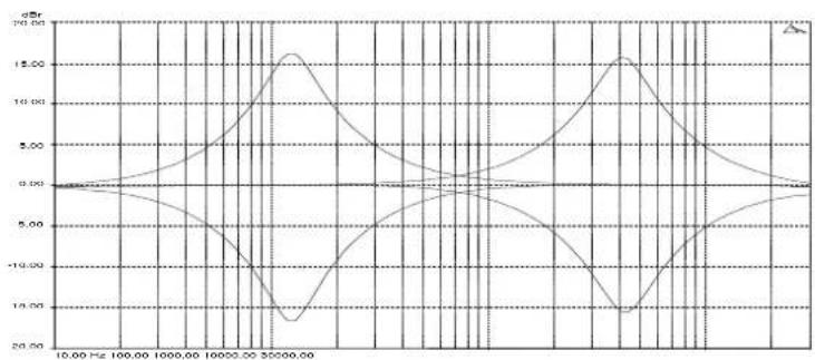
The MF (Mid Frequency) equaliser affects the middle of the audible frequency range. The frequency graduations on the sweep control are the centre frequencies of the EQ. The range has been carefully chosen to cover "boomy" frequencies around 120Hz to 250Hz which may need cutting back, or a lift at 2 to 3kHz may be required for microphone intelligibility.
line
| Frequency (Hz) | Amplitude (dB) | | -------------- | -------------- | | 10.00 | 0.00 | | 100.00 | 2.50 | | 1000.00 | 5.00 | | 10000.00 | 7.50 | | 30000.00 | 15.00 | | 10000 | 12.50 | | 15000 | 5.00 | | 30000 | 2.50 | | 15000 | -2.50 | | 30000 | -5.00 | | 15000 | -7.50 | | 30000 | -12.50 | | 15000 | -15.00 | | 30000 | -12.50 | | 15000 | -5.00 | | 30000 | 2.50 | | 15000 | 5.00 | | 30000 | 7.50 | | 15000 | 12.50 | | 30000 | 15.00 | | 15000 | 12.50 | | 30000 | 5.00 | | 15000 | 2.50 | | 30000 | 2.50 | | 15000 | 2.50 | | 30000 | 2.50 | | 15000 | 2.50 | | 30000 | 2.50 | | 15000 | 2.50 | | 30000 | 2.50 | | | 1500 | 2.5 | | 30 | 2.5 | | 3 | 2.5 | | 3 | 2.5 | | 3 | 2.5 | | 3 | 2.5 | | 3 | 2.5 | | 3 | 2.5 | | 3 | 2.5 | | 3 | 2.5 | | 3 | 2.5 | | 3 | | 3 | 2.5 | | 3 | 2.5 | | 3 | 2.5 | | 3 | 2.5 | | 3 | 2.5 | | 3 | 2.5 | | 3 | 2.5 | | 3 | 2.5 | | 3 | 2.5 |LFEQ
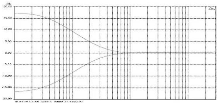
The LF (Low Frequency) equaliser affects the response at the low end of the audio range. The graph shows the response of the LF EQ at maximum cut and boost. The corner frequency is 80Hz.
line
| x | y1 | y2 | | ------ | ------ | ------ | | 10.00 | 15.00 | -20.00 | | 150.00 | 14.00 | -18.00 | | 200.00 | 12.00 | -15.00 | | 250.00 | 10.00 | -12.00 | | 300.00 | 8.00 | -10.00 | | 350.00 | 6.00 | -8.00 | | 400.00 | 4.00 | -6.00 | | 450.00 | 2.00 | -4.00 | | 500.00 | 1.00 | -2.00 | | 550.00 | 0.50 | 0.50 | | 600.00 | 0.25 | 1.55 | | 650.00 | 0.15 | 2.75 | | 700.00 | 0.1 | 4.12 | | 750.00 | 0.05 | 5.69 | | 800.00 | 0.02 | 7.49 | | 850.00 | 0.01 | 9.51 | | 900.00 | 0.0 | 11.83 | | 950.00 | -0.01 | 14.37 | | 1000.00| -0.1 | 17.16 | | 1667 | -1.6 | -18.83 | | 2337 | -3.2 | -23.89 | | 3117 | -5.4 | -31.47 | | 3897 | -7.8 | -42.43 | | 4677 | -11.6 | -57.99 | | 5467 | -16.8 | -78.43 | | 6257 | -24 | -112.47| | 7147 | -34 | -163.73| | 7937 | -48 | -239.47| | 8727 | -68 | -339.47| | 9517 | -94 | -479.99| | 13387 | -136 | -669.99| | 21277 | -216 | -919.99| | 28177 | -322 | -1239.99| | 34177 | -464 | -1699.99| | 41177 | -668 | -2299.99| | 48177 | -936 | -2999.99| | 54177 | -1264 | -3999.99| | 61177 | -1688 | -5299.99| | 68177 | -2344 | -6899.99| | 75177 | -3224 | -8899.99| | 82177 | -4424 | -11499.99| | 89177 | -6248 | -15699.99| | 96177 | -8432 | -21399.99| | 133177 | -11688 | -28699.99| | 211177 | -15888 | -38499.99| | 289177 | -21344 | -52499.99| | 367177 | -28688 | -68499.99| | 435177 | -38432 | -84499.99| | 513177 | -52484 | -112499.99| | 581177 | -68488 | -142499.99| | 650177 | -84488 | -175499.99| | 720177 | -112488| -225499.99| | 790177 | -146888| -285499.99| | 860177 | -183368| -355499.99| | 930177 | -23484| -435499.99| | 131177| -32248| -555499.99| | 218177| -46488| -685499.99| | 316177| -66888| -835499.99| | 385177| -83648| -112549.99| | 464177| -116888| -153549.99| | 533177| -168888| -213549.99| | 612177| -23484| -286549.99| | 681177| -32248| -384599.99| | 751177| -46488| -524599.99| | 821177| -66888| -684599.99| | 891177| -83648| -834599.99| | 961177| -116888|-112459.99| | 133177| -168888|-153459.99| | 211177| -23484|-223459.99| | 289177| -32248|-323459.99| | 367177| -46488|-453459.99| | 435177| -66888|-623459.99| | 513177| -83648|-763459.99| | 582177| -116888|-123345.99| | 651177| -168888|-223345.99| | 721177| -23484|-353345.99| | 791177| -32248|-523345.99| | 861177| -46488|-683345.99| | 931177| -66888|-853345.99| | 131177| -83648|-115334.5 |MONO INPUT CHANNEL


flowchart
graph TD
    A["Start"] --> B{Step 1}
    B --> C["Step 2"]
    C --> D{Step 3}
    D --> E["Step 4"]
    E --> F{Step 5}
    F --> G["End"]
Aux
This control sends a signal to an auxiliary bus. The signal is sourced pre-fade or post-fade depending on the PRE switch position. The pre-fade source selection will be affected by the channel ON/OFF switch if active. The send control varies the signal level to the bus from off (fully attenuated) to +6dB, with unity gain at the arrow.
MIX B
The MIX B switch routes the channel signal to a stereo bus which is independent of the main PGM (program) bus. The signal is post-fade and follows the PAN control. The MIX B bus can be used for creating mixes for recording or clean-feed sources for external equipment.
PAN
The pan control adjusts how the signal from the mono input channel is shared between the left and right sides of the PGM, Audition and MIX B bus. Set to the mid position, equal amounts of signal are fed to left and right, with pan set to L, none is sent to the Right bus.
AUDITION
Pressing the audition button illuminates the red LED and switches the signal from the program bus to the audition bus. The signal is post fade and follows the PAN control. The AUD switch is after the MIX B switch in the signal chain and so has no effect on the MIX B selection.
ON Switch
This mechanically latching switch operates the channel mute circuitry, turning the signal to the PGM, Audition, MIX B and Aux buses on or off. The switch is illuminated green when pressed.
There is an option to disable the switch (make permanently ON) using the option switches on the rear-panel. If this is activated, then the switch will be illuminated green regardless of whether it is pressed or not.
There is also a remote mute option wired to a D type connector on the rear panel. When this is wired and operated the REM MUTE red LED illuminates and the mute circuit is activated regardless of whether the ON switch is pressed.
SIGNAL & PEAK LEDs
The Signal LED illuminates when the pre-fader signal level is above -15dB. The Peak LED illuminates and stays on for around 0.5 seconds when a peak level is detected (pre-fader signal) within 5dB of clipping.
PFL Switch
The PFL (Pre-Fade Listen) switch sends the channel signal to the PFL bus and subsequently to the headphones/CRM speakers and the main L R meters. Used for checking the audio signal before raising the fader or unmuting the channel.
Fader
The 100mm fader controls the level of the channel signal to the left & right PGM bus, Audition bus, MIX B bus and post fade Aux.
The Mono channel faders have Fader Start switching logic available to either interface to external equipment or activate the muting circuit for the control room speaker outputs.
TELCO CHANNELS
TEL IN
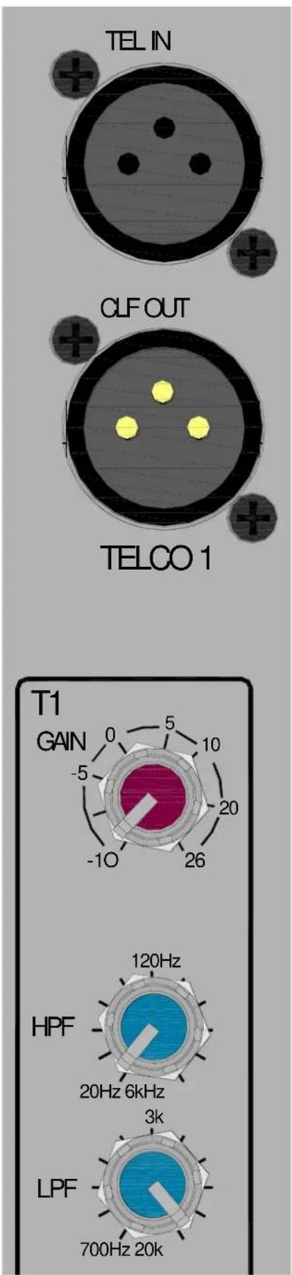
The Telephone Communication channel input XLR socket. Wired as Pin 1=Chassis, Pin 2=hot (+), Pin 3=Cold (-).
CLF OUT
Standard XLR output connector for the Clean-Feed output from the Telephone Communication channel.
Wired Pin 1=Chassis, Pin 2=hot (+), Pin 3=Cold (impedance balanced ground).
TELCO Input Gain
The Telephone Communication channel input gain control. Varies the gain applied to the TELCO input channel from -10dB to +26dB.
TELCO Channel Filters
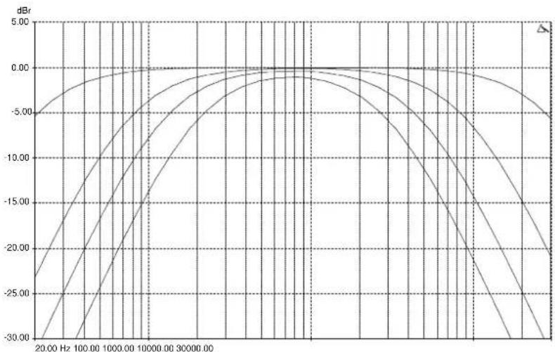
The TELCO Channel has a high pass and low pass total cut filter which is designed to allow the user to reduce the frequency range of the channel when used with a telephone caller.
The high pass filter can be varied from 20Hz (full range) to 6kHz. The low pass filter from 20kHz (full range) to 700Hz.
The default position (full range frequency response) is shown.
line
| Frequency (Hz) | Value (dB) | | -------------- | ---------- | | 20.00 | -30.00 | | 100.00 | -25.00 | | 1000.00 | -20.00 | | 10000.00 | -15.00 | | 30000.00 | -10.00 | | 30000.00 | -5.00 | | 30000.00 | 0.00 |TELCO CHANNELS
TALK
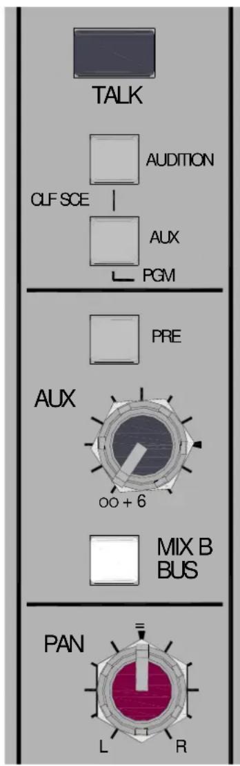
The TALK switch enables the presenter or operator to communicate with the telephone caller with the presenters channel fader down so the presenters voice does not go to the program mix.
The source for the TALK signal is one of the mono channels, pre-selected by links set within the XB-14, the factory default is mono channel 1. The signal source is pre-fade and pre-mute on the selected mono channel.
CLF SCE
The Clean-Feed Source switch selects the signal source for the TELCO cleanfeed output. With both buttons in the up position the signal will be the entire program (PGM) mix (pre main PGM fader) but without the signal from the input on that TELCO channel, so the caller does not hear any distracting echo of their voice.
If the AUX or AUDITION switch is pressed, the TELCO clean feed signal is sourced from the selected bus, but minus the signal sent from that TELCO channel.
This is a really useful feature that can enable the operator to send a mix of signals from different channels to the telephone caller, the sources may be on or off air because the sources for the AUX bus can be pre or post fader or the Audition bus can be used.
In addition, The telephone conversation could be recorded off air using the audition or aux buses, and replayed at a later time.
AUX
This control sends a signal to an auxiliary bus. The signal is sourced pre-fade or post-fade depending on the PRE switch position. The pre-fade source selection will be affected by the channel ON/OFF switch if active. The send control varies the signal level to the bus from off (fully attenuated) to +6dB, with unity gain at the arrow.
MIX B
The MIX B switch routes the channel signal to a stereo bus which is independent of the main PGM (program) and audition buses. The signal is post-fade and follows the PAN control. The MIX B bus can be used for creating mixes for recording or clean-feed sources for external equipment.
PAN
The pan control adjusts how the signal from the TELCO input channel is shared between the left and right sides of the PGM, audition and MIX B buses. Set to the mid position, equal amounts of signal are fed to left and right, with pan set to L, none is sent to the Right bus.
TELCO CHANNELS


natural_image
Pure geometric line drawing with no text, numbers, or symbolsAUDITION Switch
Pressing the audition button illuminates the red LED and switches the signal from the program bus to the audition bus. The signal is post fade and follows the PAN control. The AUD switch is after the MIX B switch in the signal chain and so has no effect on the MIX B selection.
ON Switch
This mechanically latching switch operates the channel mute circuitry, turning the signal to the PGM, Audition, MIX B and Aux buses on or off. The switch is illuminated green when pressed.
There is an option to disable the switch (make permanently ON) using the option switches on the rear-panel. If this is activated, then the switch will be illuminated green regardless of whether it is pressed or not.
There is also a remote mute option wired to a D type connector on the rear panel. When this is wired and operated the REM MUTE red LED illuminates and the mute circuit is activated regardless of whether the ON switch is pressed.
SIGNAL & PEAK LEDs
The Signal LED illuminates when the pre-fader signal level is above -15dB. The Peak LED illuminates and stays on for around 0.5 seconds when a peak level is detected (pre-fader signal) within 5dB of clipping.
PFL Switch
The PFL (Pre-Fade Listen) switch sends the channel signal to the PFL bus and subsequently to the headphones/CRM speakers and the main L R meters. Used for checking the audio signal before raising the fader or switching on the channel or raising the fader.
Fader
The 100mm fader controls the level of the TELCO channel signal to the left & right PGM bus, MIX B bus and post fade Aux.
The TELCO channel faders have fader start switching logic signals available on the rear-panel remote interface connectors for control of external equipment.
STEREO INPUT CHANNELS ST1 & ST2

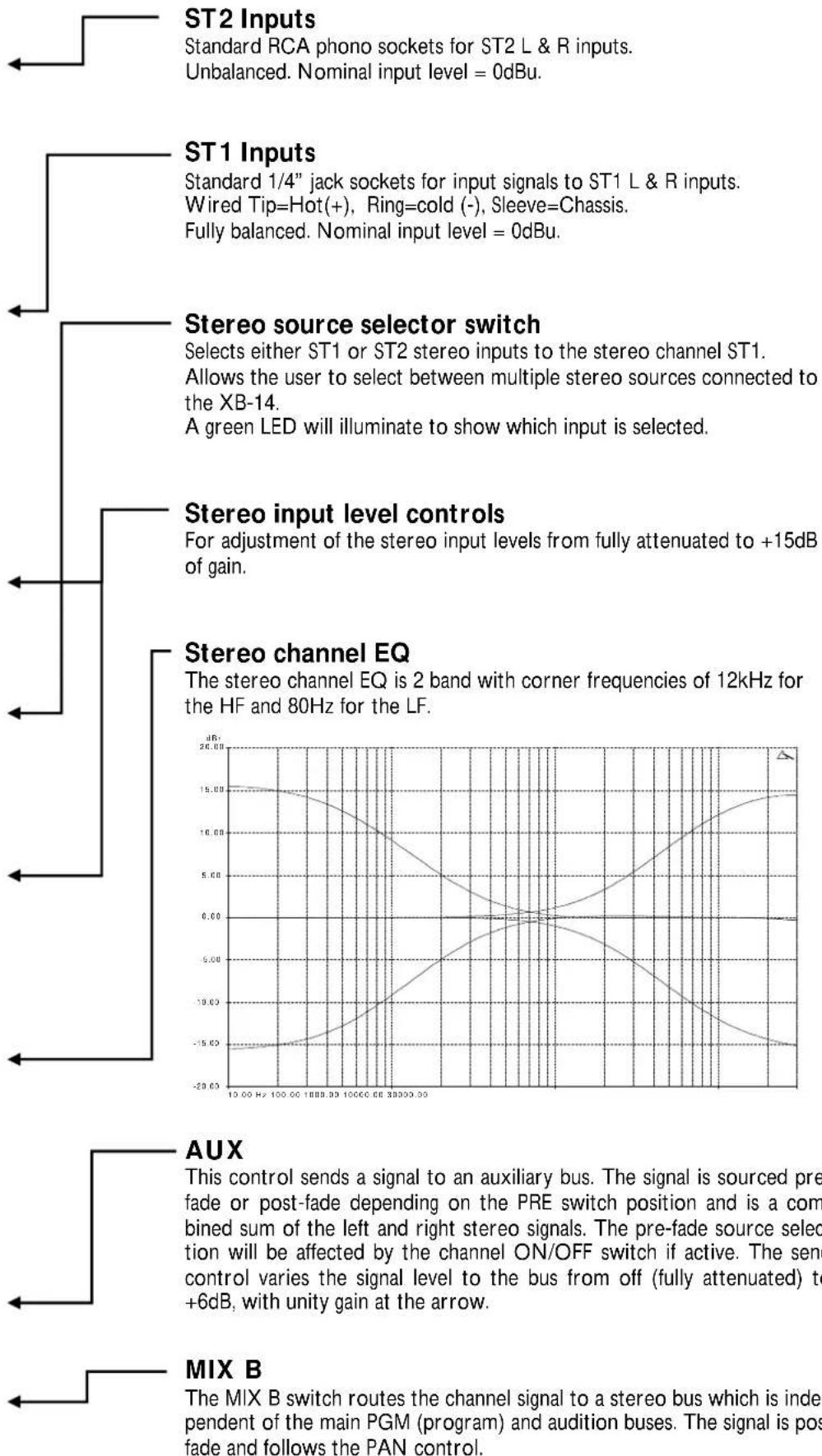
FOR CLARITY ONLY ST1 CHANNEL IS DESCRIBED HERE
line
| Input Type | Signal Amplitude (dB) | | --- | --- | | ST2 Inputs | - | | ST1 Inputs | - | | Stereo source selector switch | - | | Stereo input level controls | - | | Stereo channel EQ | - | | AUX | - | | MIX B | - |STEREO INPUT CHANNELS ST1 & ST2
FOR CLARITY ONLY ST1 CHANNEL IS DESCRIBED HERE
BAL
The balance control adjusts the relative levels of the left & right signals in the stereo input channel as they are sent to the PGM, Audition and MIX B buses. Set to the mid position, the signals are balanced equally. With the balance control set fully anticlockwise the right channel will be fully attenuated and the left channel will increase by approximately 3.5dB.
AUDITION Switch
Pressing the audition button illuminates the red LED and switches the signal from the program bus to the audition bus. The signal is post fade and follows the PAN control. The AUD switch is after the MIX B switch in the signal chain and so has no effect on the MIX B selection.
ON (+START/CUE) switch
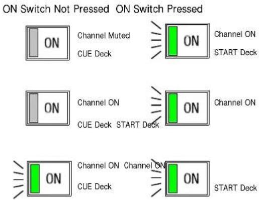
The stereo channel ON switch operates the stereo channel mute circuitry, turning the signals to the PGM, MIX B, Audition and Aux buses on or off. The switch is illuminated green when pressed.
The ON switch also activates the START/CUE logic signals (for the corresponding selected input) wired to the remote interface connector on the rear panel.
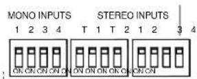
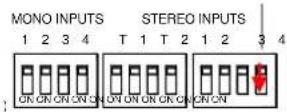
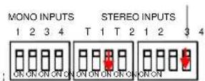
There is an option to disable the mute circuit on all the stereo channels (make the channels permanently ON) using the option switches on the rear panel. This can be done for all 4 stereo channels together, retaining the illumination switching (if the ON switch is being used for Start/Cue).
It can also be done on an individual channel basis by using the STEREO INPUTS 1,2,3&4 slide switches in which case the illumination of the switch will be jammed permanently ON.
natural_image
Three abstract line shapes with arrows pointing left, no text or symbols presentSTEREO ON Switch Optional Modes
Standard Operation
Mute
Disabled
(Always ON)
LEDs FOLLOW
SWITCH
(All stereos)
Mute
Disabled
(Always ON
All Stereos)
LEDs always
illuminated
(On ST1 only)
Fader
The 100mm fader controls the level of the stereo channel L & R signals to the PGM, MIX B, Audition and post fade Aux buses.
There is no fader start logic feature on the stereo channel faders.
SIGNAL & PEAK LEDs
The Signal LED illuminates when the pre-fader L or R signal level is above - 15dB.
The Peak LED illuminates and stays on for around 0.5 seconds when a peak level is detected (pre-fader signal) within 5dB of clipping.
PFL Switch
Sends the summed L & R stereo channel signals to the PFL bus.

Allen & Heath
STEREO INPUT CHANNELS ST3 & 4
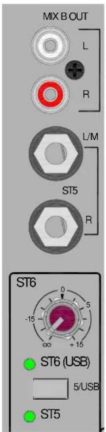
SIMILAR TO THE ST1 & 2 CHANNELS—THE DIFFERENCES ARE DETAILED HERE.
MIX B OUT
Standard RCA phono sockets for the MIX B bus output. The output level can be controlled by the MIX B Level control. Nominal level = 0dBu, unbalanced.
USB RTN (ST6) level
The source for the ST6 input is from the USB audio device, in other words from an external computer. The level control varies the gain applied to the USB audio device input signal from off (fully attenuated) to +15dB.
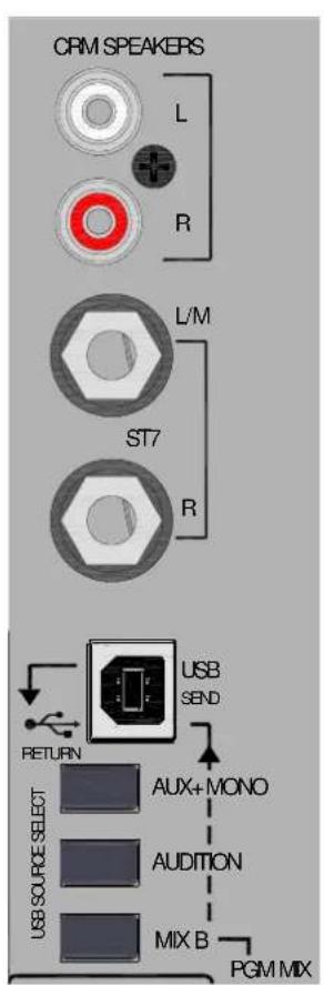
CRM SPEAKERS outputs
Standard RCA phono sockets for connecting to either powered speakers or a stereo amplifier for the control room speakers. The output level can be controlled by the CRM Speakers Level control. Nominal level = 0dBu, unbalanced.
USB audio send & return
The USB connection uses a USB1.1 compliant stereo USB audio CODEC which is also fully compliant with USB 2. The connector is a standard USB "B Type" connector. When connected to a computer (Windows or Mac) you will be able to transfer stereo audio to and from the XB-14. The signal source for the send is selected using the switches below the USB connector.
If all switches are un-pressed, the post-fader main program mix will be sent to the USB output. The priority switch matrix also gives the choice of post level MIX B, post level audition bus and AUX (left hand channel) and mono program feed (right hand channel).
The USB audio input can be selected to feed the stereo channel 4 (ST4) by selecting the stereo input 6 (ST6) to that channel.
MASTER SECTION
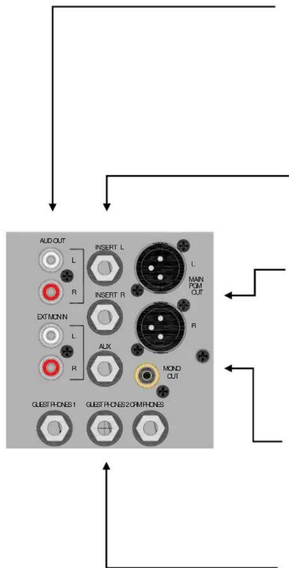
Audition Out
Standard RCA phono sockets for the Audition bus output. The output level can be controlled by the AUD Level control.
Nominal level = 0dBu, unbalanced.
External Monitor Input
Standard RCA phono sockets for a stereo signal which can be routed to either the engineers' CRM monitor headphones & speakers, or the guest headphones. It can be used for monitoring the program transmission or switching any external stereo source to the engineers or guests monitors.
The input level can be controlled with the EX MON level control.
Nominal level = 0dBu, unbalanced.
Main PGM Inserts
Standard 1/4" (6.25mm) Jack socket for unbalanced insert send and return signals.
Wired Tip=send, Ring=return, Sleeve=Chassis. Nominal level is 0dBu.
The insert point is pre the main PGM fader.
Main PGM Outputs
Standard XLR output connector for the main program mix left & right outputs.
Wired Pin 1=Chassis, Pin 2=hot (+), Pin 3=Cold (-).
Electronically balanced, nominal level = +4dBu (=0VU).
AUX Output
Standard 1/4" (6.25mm) Jack socket for aux output.
Wired Tip=Hot (+), Ring=cold (-), Sleeve=Chassis. Impedance balanced. Nominal level = 0dBu.
Mono Output
Standard RCA phono socket for the Mono PGM bus output.
The mono program bus is Nominal level = 0dBu, unbalanced.
The PGM mono output is a mono version of the main PGM stereo out but is independent of the main fader.
Headphone Output Sockets
Standard 1/4" (6.25mm) Jack sockets for the engineer/self operator and two guests.
Wired Tip=Left (+), Ring=Right (-), Sleeve=Ground.
Warning! To avoid damage to your hearing do not operate the headphones or sound system at excessively high volume. Continued exposure to high volume sound can cause frequency selective or wide range hearing loss.
MASTER SECTION
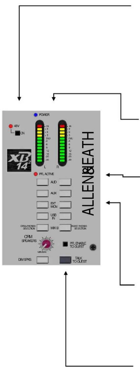
48v Phantom Power switch
Press this in to switch 48v Phantom Power to the 4 Mic input xlr connectors, if any of the microphones attached require power. Dynamic microphones won't mind being connected to a phantom powered input, but care is needed to ensure that 48v is not switched on if an xlr is used to input a signal from an electronic circuit (ie. Another mixer or keyboard).
When switching 48v on or off, or plugging in connectors to channels with 48v present, it is important (and normal procedure) to mute the channels. This will avoid loud clicks and bangs potentially getting through to the amps & speakers with the possible effect of damaging the speakers, or the audience's hearing!
Main Left & Right meters
12 segment LED meters, peak type response, the "0" position reflects nominal level at the outputs (+4dBu from the main PGM outputs). The meters display the signals from the CRM + Phones selector switches below, or the PFL (pre-fade listen) signal from any selected channels, which overrides.
PFL Active LED
Illuminates red when any one or more PFL (pre-fade listen) switch is pressed. Indicates that the meters are displaying the PFL signal rather than the signal from the selected source.
CRM + PHONES Source Selector switches
These 5 switches select the signal source for the control room speakers, headphones monitor and the meters. They work on a priority basis. If they are all up then the post-fade main PGM signals will feed the monitor circuit, if any of the switches are pressed then the PGM signal will be replaced. If more than one switch is pressed the switch nearest the meters will take priority. The PFL signal will override the selection to the meters and CRM if activated.
GUEST PHONES Source Selector switches
Similar to the CRM + PHONES selection switches, these select the source for the guest headphones output. The choices are the same as for the CRM outputs, but a different source can be selected for the guests to that selected for the operator.
The PFL signal will not be fed to the guest phones outputs unless the PFL ENABLE TO GUEST switch is pressed. This is an under-panel switch so it cannot be operated accidentally.
TALK TO GUEST switch
Pressing this switch allows the microphone channel that has been selected as the comms channel, to speak to the guest headphone feed. If the guest is listening to the program mix, for example, this will reduce in volume to a background level when the talk switch is pressed.
MASTER SECTION
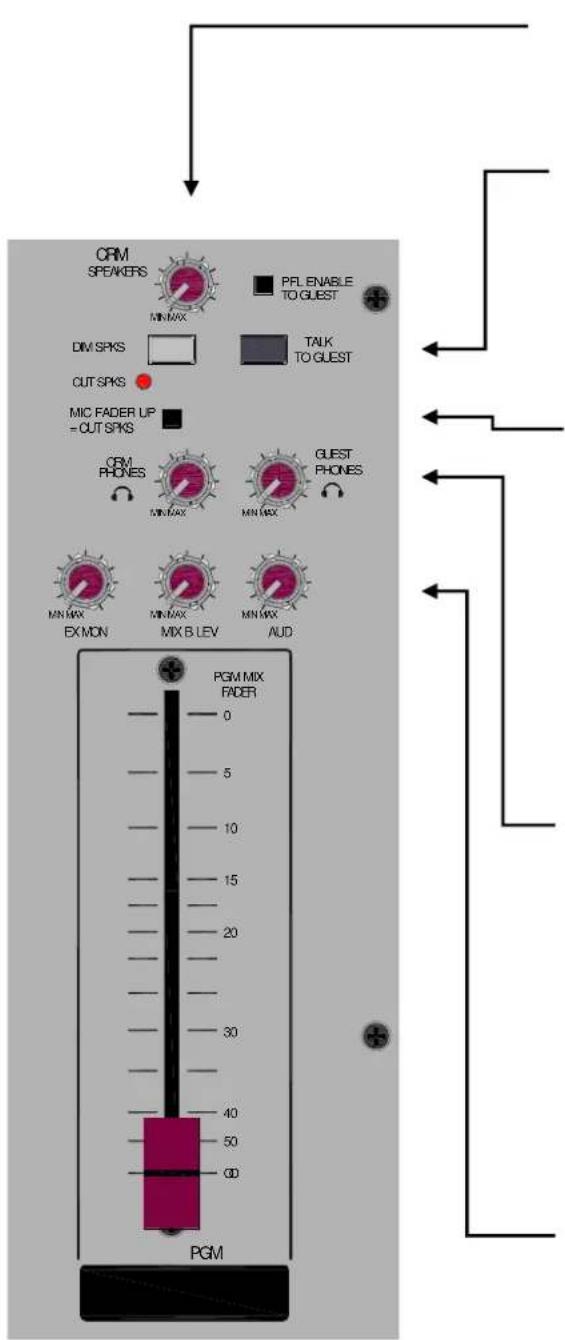
CRM Speakers level
Adjusts the level of the signal to the control room speaker outputs from off (fully attenuated) to unity gain.
DIM & Cut CRM Speakers
The Dim switch reduces the level of the control room speakers by 20dB.
The Cut CRM Speakers LED illuminates red when the control room speakers mute circuit is activated, either by external switching using the remote interface or by raising any one of the mono channel faders (if the MIC FADER UP switch has been pressed).
MIC FADER UP = CUT Speakers
An under-panel switch to enable the fader start logic switching to cut the control room speaker outputs. This is useful when the CRM speakers are in close proximity to the microphones plugged into the mono channels and acoustic feedback may occur from the speakers to the microphones.
Press the switch to enable the automatic muting.
Control Room Phones level
Adjusts the level of the operators' control room headphones from off (fully attenuated) to maximum. The headphone amplifier has a gain of 12dB.
Guest Phones level
Adjusts the level of the guests' headphones from off (fully attenuated) to maximum.
Each headphone output socket has a dedicated amplifier with a gain of 12dB.
EX MON level
This is the master level control for the external monitor stereo input. The range of adjustment is from off (fully attenuated) to unity gain.
MIX B level
This is the master level control for the MIX B stereo bus output.
The range of adjustment is from off (fully attenuated) to unity gain.
AUD level
This is the master level control for the audition stereo bus output. The range of adjustment is from off (fully attenuated) to unity gain.
Program Mix Fader
The main program mix level control. Affects the stereo PGM output, but not the mono PGM output.
0dB, or unity gain is at the top of the fader.
REMOTE INTERFACE CONNECTORS
| 15 Way D socket connector REMOTE A | |
| PIN | FUNCTION |
| 1 M1 FADER UP LOGIC (OPEN COLLECTOR OUTPUT) | |
| 2 M3 FADER UP LOGIC (OPEN COLLECTOR OUTPUT) | |
| 3 T1 FADER UP LOGIC (OPEN COLLECTOR OUTPUT) | |
| 4 M1 EXTERNAL MUTE (INPUT, ACTIVE LOW) | |
| 5 M3 EXTERNAL MUTE (INPUT, ACTIVE LOW) | |
| 6 T1 EXTERNAL MUTE (INPUT, ACTIVE LOW) | |
| 7 CUT CRM SPEAKERS (INPUT, ACTIVE LOW) | |
| 8 GROUND | |
| 9 M2 FADER UP LOGIC (OPEN COLLECTOR OUTPUT) | |
| 10 M4 FADER UP LOGIC (OPEN COLLECTOR OUTPUT) | |
| 11 T2 FADER UP LOGIC (OPEN COLLECTOR OUTPUT) | |
| 12 M2 EXTERNAL MUTE (INPUT, ACTIVE LOW) | |
| 13 M4 EXTERNAL MUTE (INPUT, ACTIVE LOW) | |
| 14 T2 EXTERNAL MUTE (INPUT, ACTIVE LOW) | |
| 15 N/C | |
| 15 Way D plug connector REMOTE B | |
| PIN | FUNCTION |
| 1 ST1 START PULSE (OPEN COLLECTOR OUTPUT) | |
| 2 ST2 START PULSE (OPEN COLLECTOR OUTPUT) | |
| 3 ST3 START PULSE (OPEN COLLECTOR OUTPUT) | |
| 4 ST4 START PULSE (OPEN COLLECTOR OUTPUT) | |
| 5 ST5 START PULSE (OPEN COLLECTOR OUTPUT) | |
| 6 ST6 START PULSE (OPEN COLLECTOR OUTPUT) | |
| 7 ST7 START PULSE (OPEN COLLECTOR OUTPUT) | |
| 8 GROUND | |
| 9 ST1 STOP/CUE PULSE (OPEN COLLECTOR OUTPUT) | |
| 10 ST2 STOP/CUE PULSE (OPEN COLLECTOR OUTPUT) | |
| 11 ST3 STOP/CUE PULSE (OPEN COLLECTOR OUTPUT) | |
| 12 ST4 STOP/CUE PULSE (OPEN COLLECTOR OUTPUT) | |
| 13 ST5 STOP/CUE PULSE (OPEN COLLECTOR OUTPUT) | |
| 14 ST6 STOP/CUE PULSE (OPEN COLLECTOR OUTPUT) | |
| 15 ST7 STOP/CUE PULSE (OPEN COLLECTOR OUTPUT) | |
Start/Cue logic
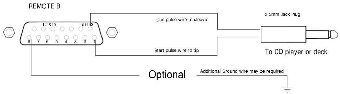
The Start/Cue logic from the Stereo channel ON switches is designed to interface to a common standard employed by Denon and Pioneer equipment. The logic signals are usually wired to a 2 pole 3.5mm jack plug where a low pulse on the tip starts the deck and a low pulse on the sleeve stops or cues the deck. There needs to be some form of ground connection between the equipment for this to work—normally effected by the audio connector leads. Notice that there are Start/Cue outputs for 7 machines even though there are only 4 Stereo channel ON switches. That's because there are dual inputs on 3 of the stereo channels making a total of 7 sources and the XB-14 only sends a Start/Cue signal to the deck selected as a source to the channel whose switch is pressed. It's clever like that!
REMOTE INTERFACE CONNECTORS
| 9 Way D socket connector EXTERNAL METER | |
| PIN | FUNCTION |
| 1 + 15V POWER | |
| 2 | -15V POWER |
| 3 | GROUND |
| 4 | LEFT METER |
| 5 | RIGHT METER |
| 6 | GROUND |
| 7 | GROUND |
| 8 | GROUND |
| 9 + 10V POWER | |
External Meter socket
This can be used to feed the main Program PGM L & R signals to external metering equipment. These are line level analogue signals, the level at 0VU will be 0dBu.
+/- 15V power is also available to power meter circuits, current draw should be kept under 100mA or so.
ON SWITCH OPTIONS
DISABLE STEREO
MUTE CIRCUIT (JAM ON)
BUT
LEDs FOLLOW SWITCH
ON ALL 4 STEREO CHs
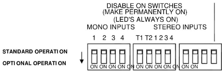
Configuration Switches
The tiny slide switches accessible on the rear panel are for configuring the XB-14's channel ON switches. In the up position, the channel ON switch will act as a normal ON/OFF switch affecting the channel signal accordingly. If the slide switch is moved down to the "ON" position, then the corresponding channel's ON switch will be disabled (made so that it is jammed ON). The green LEDs in the switch will then permanently illuminate. UNLESS....
Unless you are using the Stereo channel ON switches for transport Start/Cue and would like the channel mute circuit disabled but the switch illumination still to follow the switch position. In this case use the last switch in the row to disable the mute circuit on all 4 stereo channels, but make the illumination follow the switch position.
If you want, you can disable the Stereo channel mute circuit on an individual channel basis using the Stereo Inputs 1,2,3 & 4 slide switches individually. This will make the channel permanently on and the switch illumination also permanently on.
This may seem like a fussy complication, but could be useful if you want to revert to basic operation, where only the faders control the signal going out on air, disabling the ON switches so the operator cannot turn off the channel accidentally, but still want the switch illumination on certain stereo channels to follow the Start/Cue on the CD player or deck.
ALSO SEE P22 FOR A DIAGRAM TO EXPLAIN THESE SETTINGS.
REMOTE INTERFACE CONNECTORS
REMOTE A Connector wiring
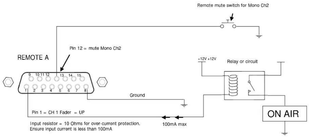
The REMOTE A connector is used for the "Fader Up" logic signals from the Mono and Telco channel faders. It is also used for remote muting of channels and control room speakers. An example of how these remote signals can be used is below:
REMOTE A Connector Example: Remote mute wiring and Fader Up interface
REMOTE B Connector Example: CD Deck start/cue from stereo channel ON switch
USB CONNECTION
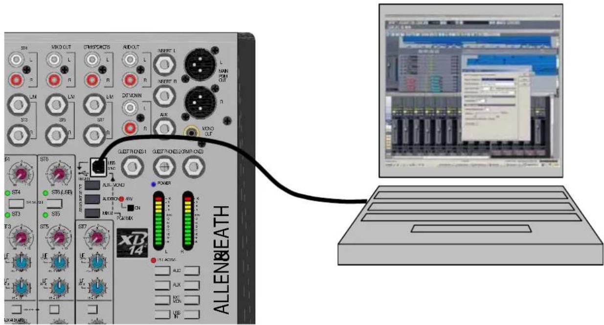
USB Audio Interface
The XB-14 is equipped with a stereo bi-directional USB 1.1 compliant audio CODEC. It is fully compliant with USB2 ports and uses standard Windows and MAC Core Audio Drivers. In other words, plug it in and your computer will find it and be able to transfer audio to and from the USB device.
You will need some form of audio software running on your computer for playback/recording or a voice over internet phone, but on a basic level, you can use your computers media player to play straight to the XB-14 device.
Just a couple of points to look out for:
W indows XP/Vista:
When you plug in your XB-14 USB interface to your computer, if the volume level is low or inaudible, check the device volume in control panel/Sounds and Audio Devices/Volume. Set the volume to High.
W indows 7:
At present, Windows 7 treats the USB audio device as a microphone source instead if a line input, so set the device volume level much lower, we found setting to 3 is ideal.
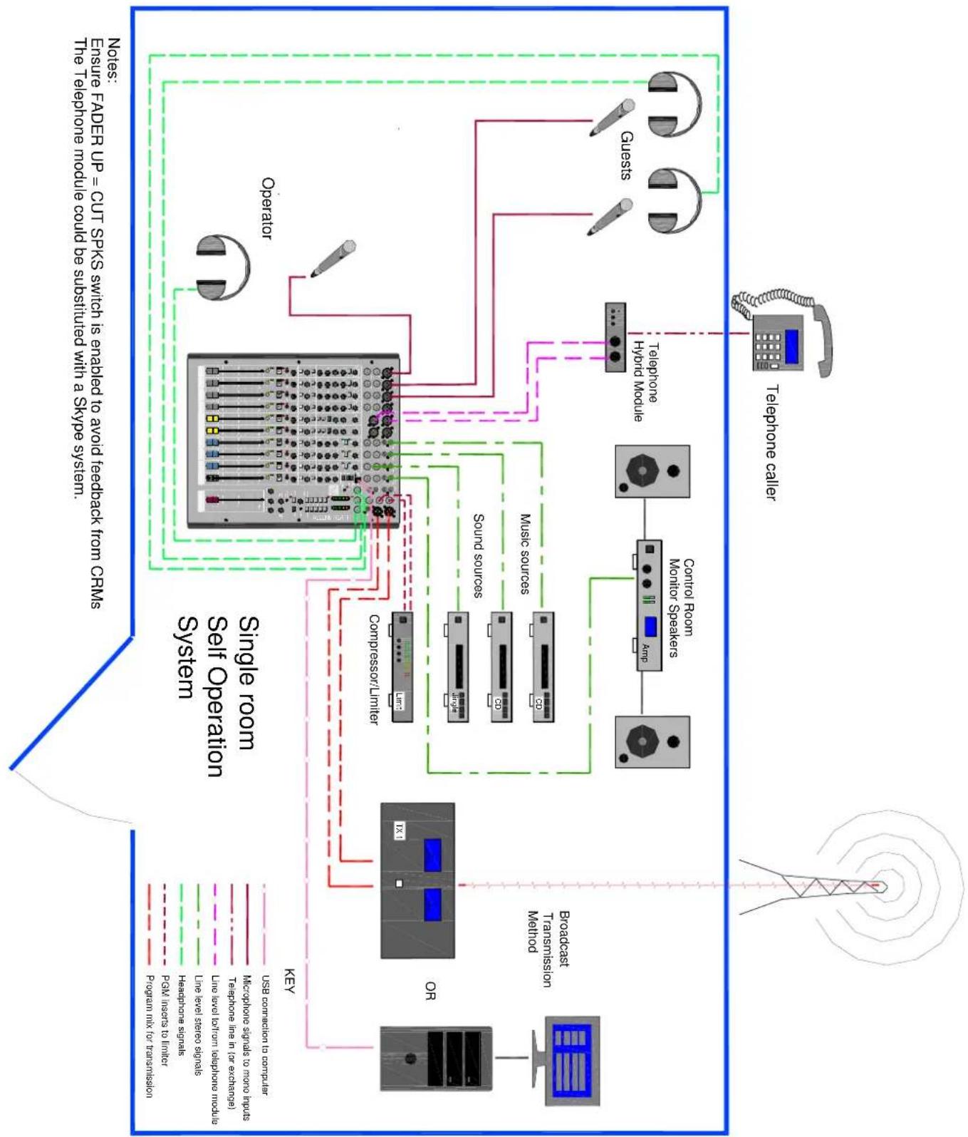
APPLICATION DIAGRAM: SELF OPERATION
flowchart
graph TD
    A["Single Room Set Operation System"] --> B["Operator"]
    A --> C["Telephone calier"]
    A --> D["Audio Sources"]
    A --> E["Audio Signals"]
    A --> F["Audio Audio Signals"]
    A --> G["Audio Level Audio Signals"]
    A --> H["Audio Level Audio Listening Modules"]
    A --> I["Audio Level In (or exchange)"]
    A --> J["Audio Signals in (or exchange)"]
    A --> K["Audio Signals in (or exchange)"]
    A --> L["Audio Signals in (or exchange)"]
    A --> M["Audio Signals in (or exchange)"]
    A --> N["Audio Signals in (or exchange)"]
    A --> O["Audio Signals in (or exchange)"]
    A --> P["Audio Signals in (or exchange)"]
    A --> Q["Audio Signals in (or exchange)"]
    A --> R["Audio Signals in (or exchange)"]
    A --> S["Audio Signals in (or exchange)"]
    A --> T["Audio Signals in (or exchange)"]
    A --> U["Audio Signals in (or exchange)"]
    A --> V["Audio Signals in (or exchange)"]
    A --> W["Audio Signals in (or exchange)"]
    A --> X["Audio Signals in (or exchange)"]
    A --> Y["Audio Signals in (or exchange)"]
    A --> Z["Audio Signals in (or exchange)"]
    A --> AA["Audio Signals in (or exchange)"]
    A --> AB["Audio Signals in (or exchange)"]
    A --> AC["Audio Signals in (or exchange)"]
    A --> AD["Audio Signals in (or exchange)"]
    A --> AE["Audio Signals in (or exchange)"]
    A --> AF["Audio Signals in (or exchange)"]
    A --> AG["Audio Signals in (or exchange)"]
    A --> AH["Audio Signals in (or exchange)"]
    A --> AI["Audio Signals in (or exchange)"]
    A --> AJ["Audio Signals in (or exchange)"]
    A --> AK["Audio Signals in (or exchange)"]
    A --> AL["Audio Signals in (or exchange)"]
    A --> AM["Audio Signals in (or exchange)"]
    A --> AN["Audio Signals in (or exchange)"]
    A --> AO["Audio Signals in (or exchange)"]
    A --> AP["Audio Signals in (or exchange)"]
    A --> AQ["Audio Signals in (or exchange)"]
    A --> AR["Audio Signals in (or exchange)"]
    A --> AS["Audio Signals in (or exchange)"]
    A --> AT["Audio Signals in (or exchange)"]
    A --> AU["Audio Signals in (or exchange)"]
    A --> AV["Audio Signals in (or exchange)"]
    A --> AW["Audio Signals in (or exchange)"]
    A --> AX["Audio Signals in (or exchange)"]
    A --> AY["Audio Signals in (or exchange)"]
    A --> AZ["Audio Signals in (or exchange)"]
    A --> BA["Audio Signals in (or exchange)"]
    A --> BB["Audio Signals in (or exchange)"]
    A --> BC["Audio Signals in (or exchange)"]
    A --> BD["Audio Signals in (or exchange)"]
    A --> BE["Audio Signals in (or exchange)"]
    A --> BF["Audio Signals in (or exchange)"]
    A --> BG["Audio Signals in (or exchange)"]
    A --> BH["Audio Signals in (or exchange)"]
    A --> BI["Audio Signals in (or exchange)"]
    A --> BJ["Audio Signals in (or exchange)"]
    A --> BK["Audio Signals in (or exchange)"]
    A --> BL["Audio Signals in (or exchange)"]
    A --> BM["Audio Signals in (or exchange)"]
    A --> BN["Audio Signals in (or exchange)"]
    A --> BO["Audio Signals in (or exchange)"]
    A --> BP["Audio Signals in (or exchange)"]
    A --> BQ["Audio Signals in (or exchange)"]
    A --> BR["Audio Signals in (or exchange)"]
    A --> BS["Audio Signals in (or exchange)"]
    A --> BT["Audio Signals in (or exchange)"]
    A --> BU["Audio Signals in (or exchange)"]
    A --> BV["Audio Signals in (or exchange)"]
    A --> BW["Audio Signals in (or exchange)"]
    A --> BX["Audio Signals in (or exchange)"]
    A --> BY["Audio Signals in (or exchange)"]
    A --> BZ["Audio Signals in (or exchange)"]
    A --> CA["Audio Signals in (or exchange)"]
    A --> CB["Audio Signals in (or exchange)"]
    A --> CC["Audio Signals in (or exchange)"]
    A --> CD["Audio Signals in (or exchange)"]
    A --> CE["Audio Signals in (or exchange)"]
    A --> CF["Audio Signals in (or exchange)"]
    A --> CG["Audio Signals in (or exchange)"]
    A --> CH["Audio Signals in (or exchange)"]
    A --> CI["Audio Signals in (or exchange)"]
    A --> CJ["Audio Signals in (or exchange)"]
    A --> CK["Audio Signals in (or exchange)"]
    A --> CL["Audio Signals in (or exchange)"]
    A --> CD
    A --> CD
    style A fill:#f9f,stroke:#333
    style B fill:#ccf,stroke:#333
    style C fill:#cfc,stroke:#333
    style D fill:#fcc,stroke:#333
    style E fill:#cff,stroke:#333
    style F fill:#ffc,stroke:#333
    style G fill:#fcc,stroke:#333
    style H fill:#cfc,stroke:#333
    style I fill:#fcc,stroke:#333
    style J fill:#cfc,stroke:#333
    style K fill:#fcc,stroke:#333
    style L fill:#cfc,stroke:#333
    style M fill:#fcc,stroke:#333
    style N fill:#cfc,stroke:#333
    style O fill:#fcc,stroke:#333
    style P fill:#cfc,stroke:#333
    style Q fill:#fcc,stroke:#333
    style R fill:#cfc,stroke:#333
    style S fill:#fcc,stroke:#333
    style T fill:#cfc,stroke:#333
    style U fill:#fcc,stroke:#333
    style V fill:#cfc,stroke:#333
    style W fill:#fcc,stroke:#333
    style X fill:#cfc,stroke:#333
    style Y fill:#fcc,stroke:#333
    style Z fill:#cfc,stroke:#333
    style AA fill:#fcc,stroke:#333
    style AB fill:#cfc,stroke:#333
    style AC fill:#fcc,stroke:#333
    style AD fill:#cfc,stroke:#333
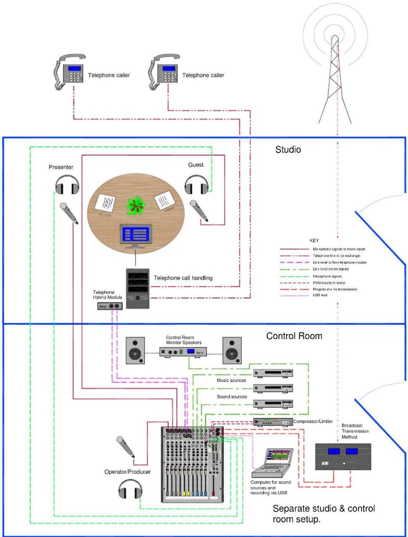
APPLICATION DIAGRAM: STUDIO+CONTROL ROOM
flowchart
graph TD
    subgraph Studio
        A["Telephone caller"] --> B["Speaker"]
        C["Telephone caller"] --> B
        B --> D["Telephone Hybrid Module"]
        D --> E["Presenter"]
        F["Guest"] --> D
    end

    subgraph Control Room
        G["Control Room Monitor Speakers"] --> H["Audio"]
        I["Music sources"] --> H
        J["Sound sources"] --> H
        K["Compressor/Limiter"] --> H
        L["Operator/Producer"] --> H
        M["Computer for sound sources and recording via USB"] --> H
    end

    style Studio fill:#f9f,stroke:#333
    style Control Room fill:#ccf,stroke:#333
    style Server fill:#cfc,stroke:#333
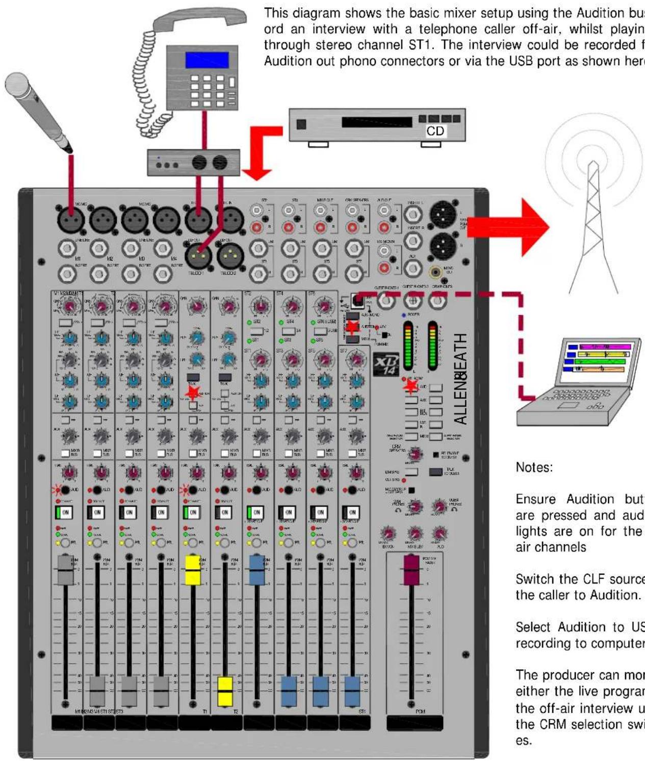
APPLICATION TIPS: OFF-AIR CALL RECORDING
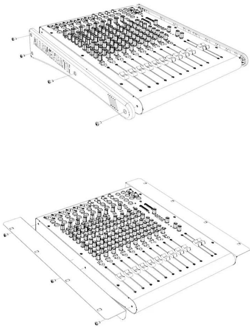
FIXING TO A RACK OR FURNITURE
The XB-14 can be fitted to a 19" rack or incorporated into studio furniture using the optional 19" rack fixing kit.
The following pictures give you an idea of how the rack fixing kit is fitted to the XB-14.
Should you decide to purchase the kit, please follow the fitting instructions provided with the kit.
The rack mounting kit part number is: ZED1402-RK19
WIRING NOTES
Insert cable wiring
flowchart
graph TD
    A["INSERT"] --> B["RETURN"]
    B --> C["SEND"]
    C --> D["LINK RING TO SLEEVE TO UNBALANCE"]
    D --> E["PROCESSOR"]
    E --> F["OUT"]
    E --> G["IN"]
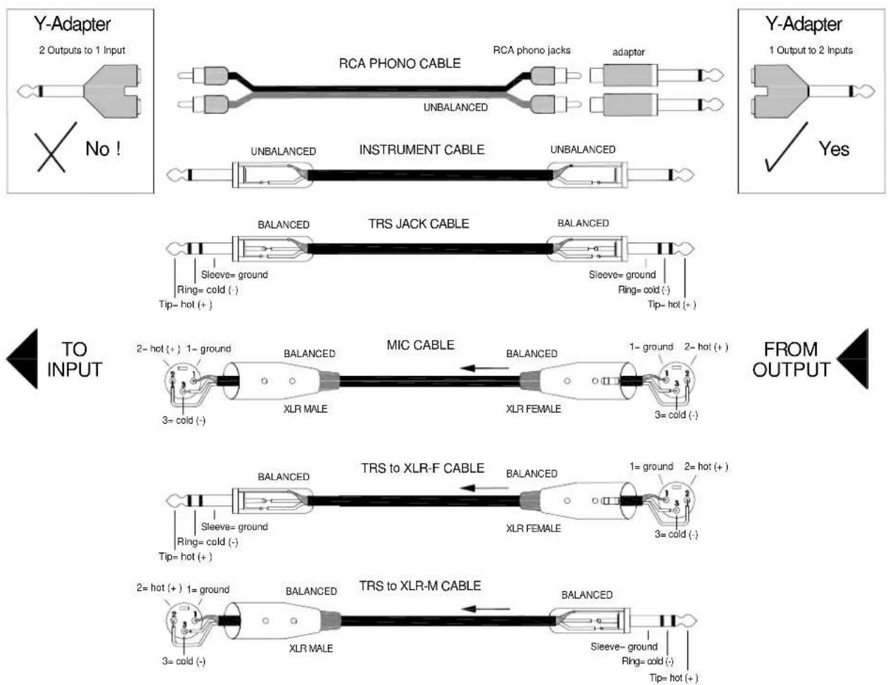
General Wiring Information
PRODUCT SUPPORT
Investigate ALLEN & HEATH's other ranges at www.allen-heath.com
natural_image
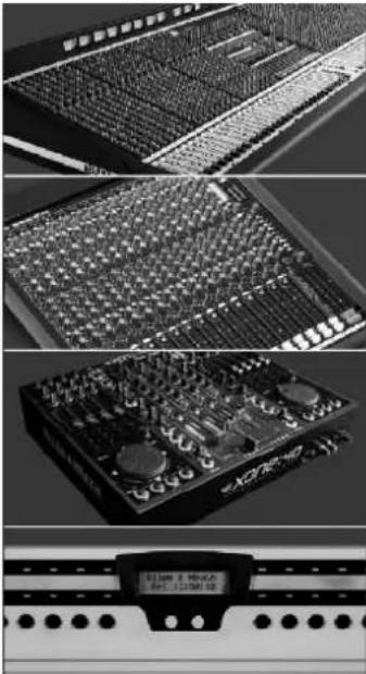
Close-up of various audio equipment modules including audio/video and audio recording systems (no visible text or labels)Large Live Sound mixers — iLive digital, ML and GL Series
Small Format Live Sound mixers — ZED, MixWizards, PA Series, XB
DJ products — Xone Series
Sound Management Series — iDR Series
Registering your product
Thank you for buying the Allen & Heath XB-14 mixer. We hope that you are happy with it and that you or your end users enjoy many years of faithful service with it.
Please go to www.allen-heath.com/register.asp and register your product's serial number and your details. By registering with us and becoming an official Registered User, you will ensure that any warranty claim you might make is actioned quickly and with the minimum delay.
Alternatively, you may either copy or cut off this section of the page, fill in the details, and return it by mail to:
Allen & Heath Ltd, Kernick Industrial Estate, Penryn, Cornwall TR10 9LU, UK
| SERIAL NUMBER | |
| Please return this section of the card by mail and retain the other part for your records. You can also register online at www.allen-health.com. Thanks for your help. Your Name: | |
| Company Name: | |
| Address 1: | |
| Address 2: | |
| Town/City: | County/State: |
| Country: | Postcode/Zip: |
| Telephone: | |
| Email: | |
| Why did you choose this console? | |
| Which other products did you you consider before choosing A&H? | |
| Is there any thing you would like to improve on this mixer? | |
| What audio magazines do you read? | |
| If you were going to design a mixer for your work, what are the 6 most important features it should have (in order of importance) 1 | 2 |
| 3 | 4 |
| 5 | 6 |
SERVICE OPTIONS
CAUTION
These servicing instructions are for use by qualified service personnel only. To reduce the risk of electric shock do not perform any servicing other than that contained in the operating instructions unless you are qualified to do so.
The XB-14 mixer has a versatile architecture which should satisfy most applications that you may encounter without modification. However, the following internal options provide alternative settings for those applications that may demand them.
Access is required to internal assemblies. There are a mixture of pluggable jumpers, cuttable wire links and solder bridge options inside the unit that can be modified to change mixer functionality.
NOTE: We advise that the modifications below are carried out by an authorised Allen & Heath service centre. The following information is provided to give the user an idea of how the console can be modified if required.
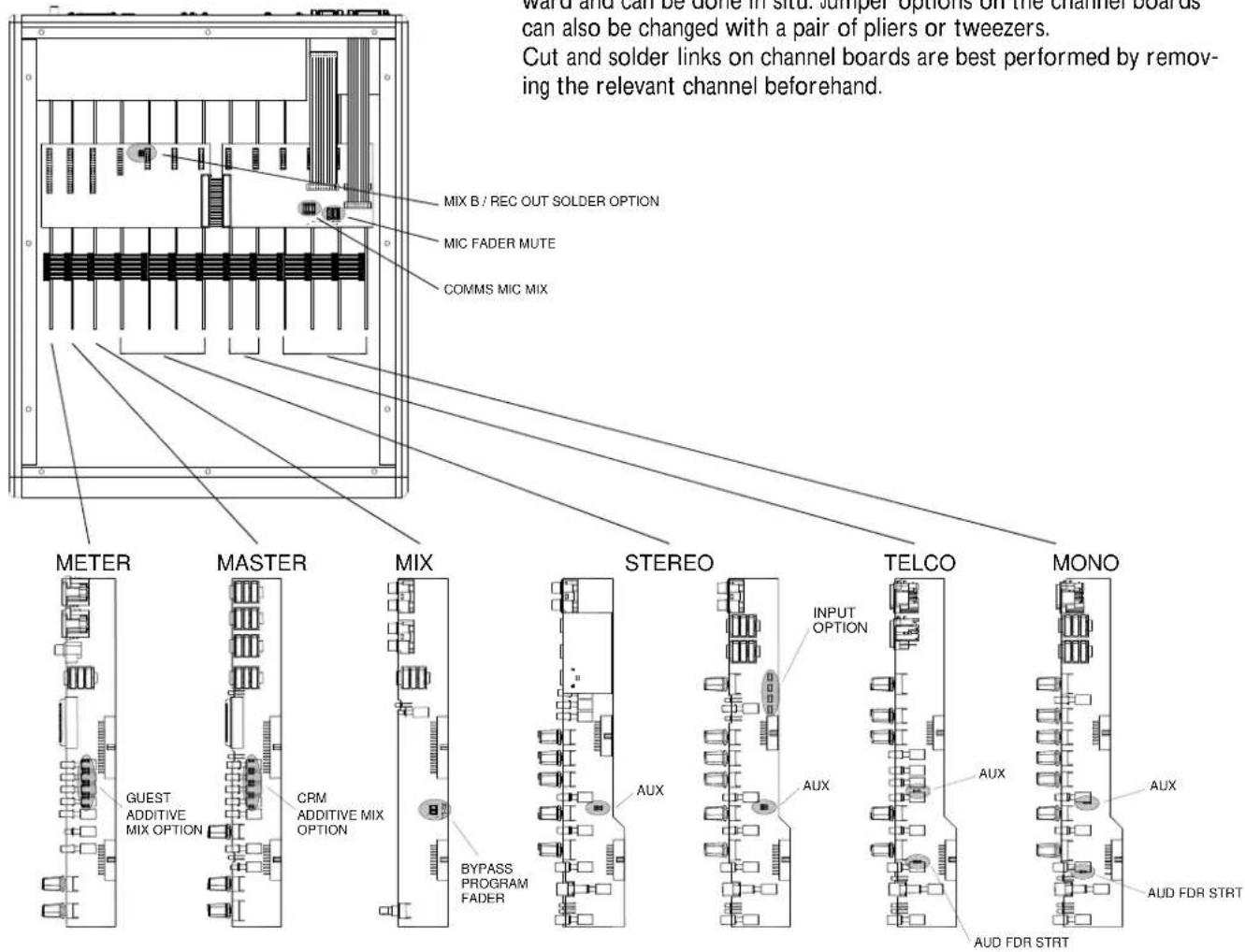
The diagram below shows the mixer with the rear cover removed.
Modifications to the rear mounted boards are relatively straightforward and can be done in situ. Jumper options on the channel boards can also be changed with a pair of pliers or tweezers.
Cut and solder links on channel boards are best performed by removing the relevant channel beforehand.
SERVICE OPTIONS
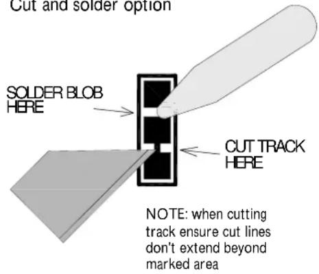
Cut and solder option
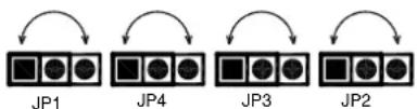
Stereo channel jumpers
flowchart
graph TD
    A["JP8"] --> B["PGM FADER BYPASS"]
    C["JP7"] --> B
    D["CN16"] --> B
    E["CN17"] --> B
    B --> F["Arrow Up"]
    B --> G["Arrow Down"]
Additive mix options


Add a solder bridge to each pair of pads
AUX Pre ON switch / Pre fade option (Mono, Telco and stereo channels)
This is a cut and solder link that sets the action of the AUX pre switch when it is in the down position.
The default setting is prefade which sources the audio signal after the ON switch but before the channel fader. The option when modified sources the signal pre ON switch and post EQ.
Audition fader start option (Mono and telco channels only)
Cut and solder link. The default for this option is to disable the channel fader start signal if the audition bus button is depressed. If the fader start option is required with the audition bus then cut and re-solder this link.
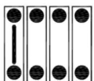
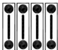
Stereo channel input option (channels ST1 - 3 only)
This option enables the stereo sources for these channels to be mixed and fed into the channel together. Simply move the position of all 4 jumpers to their opposing position to enable this option.
The red gain pots can still be used to set relative levels. The green selection LEDs will both stay on to indicate that both channels are being mixed. The main channel fader now controls both inputs.
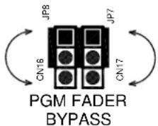
Program fader bypass (Mix PCB)
By moving the position of these 2 jumpers, the main program fader will be bypassed. This eliminates the possibility of the program fader being accidentally pulled down.
CRM / Guest additive mix option (Master & meter PCBs)
By bridging all eight solder links on the master and meter PCBs respectively, the feed selection buttons on the right hand side of the mixer are changed from priority mix to additive mix. The default setting is priority mixing where pressing a button higher up on the mixer cuts the previous signal to listen to the selected signal. In additive mixing mode the bottom button still priority switches between the main program mix and Mix B but all other feeds are mixed in to the signal when pressed.
Mix B / Rec out solder option (Distribution PCB)
Cut and solder link. Cutting and re-soldering these 2 links changes the Mix B out phono sockets to provide a pre fader program mix for recording purposes.
M1 M2 M3 M4 M1
COMMS MIC
MIX
M2 M3 M4
FADERMIC
MUTE
Comms mic mix option (Logic PCB)
Cutting or adding wire links here determines the source of the microphone signal that is used to talk to telephone callers and studio guests with the mixer talk buttons. The signal is sourced after the channel gain pot and so is not affected by the channel faders. A single source or a mix of sources can be used. The default is M1.
Mic fader mute option (Logic PCB)
Cutting or adding wire links here selects which microphone channels will mute the control room speakers when a channel fader is raised and the corresponding ON switch depressed. The default is that all mic channels will mute the control room feed but any combination can be used.

- Limited One Year Warranty
- Conditions Of Warranty
- PACKED ITEMS
- SAFETY INSTRUCTIONS
- ATTENTION: RISQUE DE CHOC ELECTRIQUE – NE PAS OUVRIR
- WARNING: This equipment must be earthed.
- Important Mains plug wiring instructions
- General Precautions:
- CONTENTS
- PANEL DRAWINGS
- INTRODUCTION TO THEXB-14
- Background overview:
- Multi-application:
- Mic/Line Pre-amps:
- EQ:
- AUX bus:
- MIX B:
- Audition bus:
- Channel signal/peak indicators:
- Remote Control:
- USB:
- Guest headphones:
- Output matrix:
- Electronically balanced outputs:
- Self operation or Producer operated:
- SPECIFICATIONS
- Dimensions
- MONO INPUT CHANNEL
- Mic Input Socket
- Line Input Jack Socket
- Insert Jack Socket
- Gain Control
- 100Hz High Pass Filter
- HFEQ
- MF EQ
- LFEQ
- Aux
- MIX B
- PAN
- AUDITION
- ON Switch
- SIGNAL & PEAK LEDs
- PFL Switch
- Fader
- TELCO CHANNELS
- TEL IN
- CLF OUT
- TELCO Input Gain
- TELCO Channel Filters
- TALK
- CLF SCE
- AUDITION Switch
- STEREO INPUT CHANNELS ST1 & ST2
- FOR CLARITY ONLY ST1 CHANNEL IS DESCRIBED HERE
- BAL
- ON (+START/CUE) switch
- STEREO INPUT CHANNELS ST3 & 4
- SIMILAR TO THE ST1 & 2 CHANNELS—THE DIFFERENCES ARE DETAILED HERE.
- MIX B OUT
- USB RTN (ST6) level
- CRM SPEAKERS outputs
- USB audio send & return
- MASTER SECTION
- Audition Out
- External Monitor Input
- Main PGM Inserts
- Main PGM Outputs
- AUX Output
- Mono Output
- Headphone Output Sockets
- 48v Phantom Power switch
- Main Left & Right meters
- PFL Active LED
- CRM + PHONES Source Selector switches
- GUEST PHONES Source Selector switches
- TALK TO GUEST switch
- CRM Speakers level
- DIM & Cut CRM Speakers
- MIC FADER UP = CUT Speakers
- Control Room Phones level
- Guest Phones level
- EX MON level
- MIX B level
- AUD level
- Program Mix Fader
- REMOTE INTERFACE CONNECTORS
- Start/Cue logic
- External Meter socket
- ON SWITCH OPTIONS
- Configuration Switches
- REMOTE A Connector wiring
- USB CONNECTION
- USB Audio Interface
- W indows XP/Vista:
- W indows 7:
- APPLICATION DIAGRAM: SELF OPERATION
- APPLICATION TIPS: OFF-AIR CALL RECORDING
- FIXING TO A RACK OR FURNITURE
- WIRING NOTES
- PRODUCT SUPPORT
- Investigate ALLEN & HEATH's other ranges at www.allen-heath.com
- Registering your product
- SERVICE OPTIONS
- CAUTION
Brand : ALLEN & HEATH
Model : XB-14²
Category : Blender