
SB46 - Snow brushcutter Cocraft - Free user manual and instructions
Find the device manual for free SB46 Cocraft in PDF.


| Product Type | Snow Thrower |
| Model | SB46 |
| Brand | Cocraft |
| Clearing Width | 46 cm (18 inches) |
| Intake Height | 30 cm (12 inches) |
| Throwing Distance | Up to 10 meters |
| Number of Stages | Single stage |
| Engine Displacement | 196 cc |
| Power Source | Petrol (gasoline) |
| Starting System | Recoil start |
| Drive Type | Manual push |
| Wheel Type | Pneumatic tires |
| Chute Rotation | Manual 180 degrees |
| Dimensions (L x W x H) | 90 x 55 x 60 cm |
| Weight | 25 kg |
| Fuel Tank Capacity | 1.0 L |
| Oil Capacity | 0.5 L |
| Maintenance | Check oil before each use, clean after each use, replace spark plug annually |
| Safety Features | Engine brake, safety key, warning labels |
| Spare Parts Availability | Available from Cocraft or authorized dealers |
| Repairability | Moderate; common parts replaceable by user |
| Warranty | 2 years |
Frequently Asked Questions - SB46 Cocraft
User questions about SB46 Cocraft
0 question about this device. Answer the ones you know or ask your own.
Ask a new question about this device
Download the instructions for your Snow brushcutter in PDF format for free! Find your manual SB46 - Cocraft and take your electronic device back in hand. On this page are published all the documents necessary for the use of your device. SB46 by Cocraft.
USER MANUAL SB46 Cocraft
Read the entire instruction manual carefully and make sure that you fully understand it before you use the equipment. Keep the manual for future reference.
Viktig information:
natural_image
Top-down view of a blue and black lawn mower with red buttons, shown against a dark background (no text or symbols visible)Art.no Model
18-4456
31-5053
DB5013-UK
DB5013
Ver. 20200716
Original instructions
Bruksanvisning i original
Please read the entire instruction manual before using the product and save it for future reference.
We reserve the right for any errors in text or images and any necessary changes made to technical data.
If you have any questions regarding technical problems please contact our Customer Services.
Safety

Double insulated for additional protection.

Conforms to relevant safety standards.

Read the entire instruction manual before use.

General hazard warning symbol. Specific safety precautions are required by the user.

Keep children and pets a safe distance away from the machine.
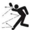
Beware of flying objects. Make sure onlookers are kept at a safe distance.
This product should be disposed of in accordance with local regulations. If you are unsure how to proceed, contact your local authority.
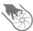
Never insert your hands into the discharge chute.
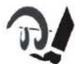
Danger – rotating feed screw.

Danger – risk of electric shock (machines with electric start). Never start the machine from the mains (230 V) under rainy conditions.
- The motor of the snow blower is fitted with an overload safety cut-off device which protects the motor by switching it off if it is overloaded. The overload safety cut-off device does not have a reset button, it resets automatically when the motor has cooled down.
- If the motor cuts out, let it cool down before switching it on again.
General safety precautions
- The snow blower must not be used by anyone (including children) suffering from physical or mental impairment. This product should not be used by anyone that has not read the instruction manual unless they have been instructed in its use by someone who will take responsibility for their safety.
- Read carefully through the instructions and inform yourself about all controls and functions and how to correctly use the snow blower.
- Never let children or others who do not have the adequate knowledge of these instructions use the snow blower. Local ordinances can have restrictions regarding the user's age.
- Remember that the user/driver is always ultimately responsible for accidents caused by use of the snow blower.
- Be careful not to fall or slip, especially when the snow blower is in reverse.
- Never use the snow blower whilst under the influence of drugs, alcohol or medicine. Do not use the product if you are tired or sick.
- The snow blower must only be repaired by qualified staff and only using original parts.
- Never use accessories not approved for use by the manufacturer or the retailer where the snow blower was purchased.
Preparations
- Make sure that the area being cleared is free from loose and foreign objects.
- Remove all service tools/keys before switching the snow blower on. A spanner or other tool which has been left on a rotating part of the blower could result in an injury.
• Make sure that the controls are easily manoeuvrable and that they return to their original position when released. - Pre-plan the area to be cleared in order to avoid personal or property damage by flying objects.
- Never use the snow blower without proper clothing. Use appropriate footwear with solid traction especially in slippery conditions.
- Under no circumstances may maintenance and service be performed when the engine is on (unless otherwise instructed in the instruction manual).
• Always use safety glasses or a visor when operating or carrying out maintenance on the snow blower. - Let the snow blower adjust to outdoor temperatures before use.
Electrical safety
- If using an extension lead, make sure that it is designed for outdoor use.
- Never modify an extension lead or its plug in any way. Unmodified plugs and suitable wall sockets minimize the risk of electric shocks.
- Do not abuse the mains lead. Never use the mains lead or extension lead to pull or jerk the plug from the wall socket. Keep electrical leads away from heat, oil, sharp edges and moving parts. Never use a damaged mains or extension lead.
- Never use the snow blower if its on/off switch is damaged or malfunctioning. Make sure that it is repaired by a qualified electrician before using it.
Safety precautions during use
- Make sure to keep hands and feet away from rotating parts. Avoid the discharge chute.
- The snow blower cannot be used for any other purpose than for removing snow.
- Be careful when using on gravel paths, pavement and roads. Be attentive for possible hazards and nearby traffic. Avoid steep inclines.
- Never point the discharge chute towards public roads or traffic.
- Stop the engine immediately if you have struck a foreign object. Inspect the machine carefully after such an incident. Do not reuse the snow blower until any possible damage has been repaired.
-
If the snow blower begins to vibrate abnormally, turn off the engine immediately and find the cause. Vibrations are normally a sign of problems.
-
Existing safety features may not be disconnected or made inoperative.
- Never use the snow blower in the vicinity of fences, cars, windows, inclines, etc. without properly adjusting the discharge chute.
• Always keep children and pets away from the areas to be cleared of snow. - Never overload the blower by driving it too fast.
- Be very careful when reversing. Always look behind you for possible obstacles.
- Never point the chute towards onlookers. Never let anyone stand in front of the snow blower.
- Never use the snow blower in conditions of inadequate visibility or improper lighting.
- Make sure you are well-balanced and have a firm grip on the handles while using the snow blower.
- Never use the snow blower on roofs.
Safety instructions specific to snow blowers
- Read the instruction manual thoroughly. Familiarize yourself with all the controls and functions of the snow blower before attempting to use it. It is very important that you know how to switch the snow blower on and off and how to disengage the drive.
- Make sure that the discharge chute is fitted correctly and undamaged and that all the controls move smoothly and return to their original positions when released. If any part of the snow blower is missing or damaged, it must be repaired/replaced before use.
- Pre-plan the area to be cleared in order to avoid personal or property damage by flying objects.
- Always unplug the mains lead before clearing snow blockages from the feed screw, impeller housing or discharge chute. Note: Use a suitable tool such as a plastic or wooden stick - never your hands.
- Never leave the snow blower unsupervised when it is connected to an electrical socket. Unplug the mains lead and remove the ignition key before leaving the snow blower.
- All safety devices and guards must be in place and working properly before the snow blower is used.
- If the mains and/or extension lead is damaged in any way during use, stop work immediately and unplug it. Have the lead replaced or repaired before continuing work.
- If any part of the snow blower has been replaced, all the functions of the snow blower should be tested before snow clearing is commenced.
• Always unplug the mains lead and remove the ignition key before relocating the snow blower. - Always respect local regulations regarding noise and exhaust emissions. Show consideration for your neighbours and choose a reasonable time to begin work.
Contents
The snow blower comes with the following accessories:
- 3 cable clips
- Chute crank, upper and lower part
• Key
Buttons and functions
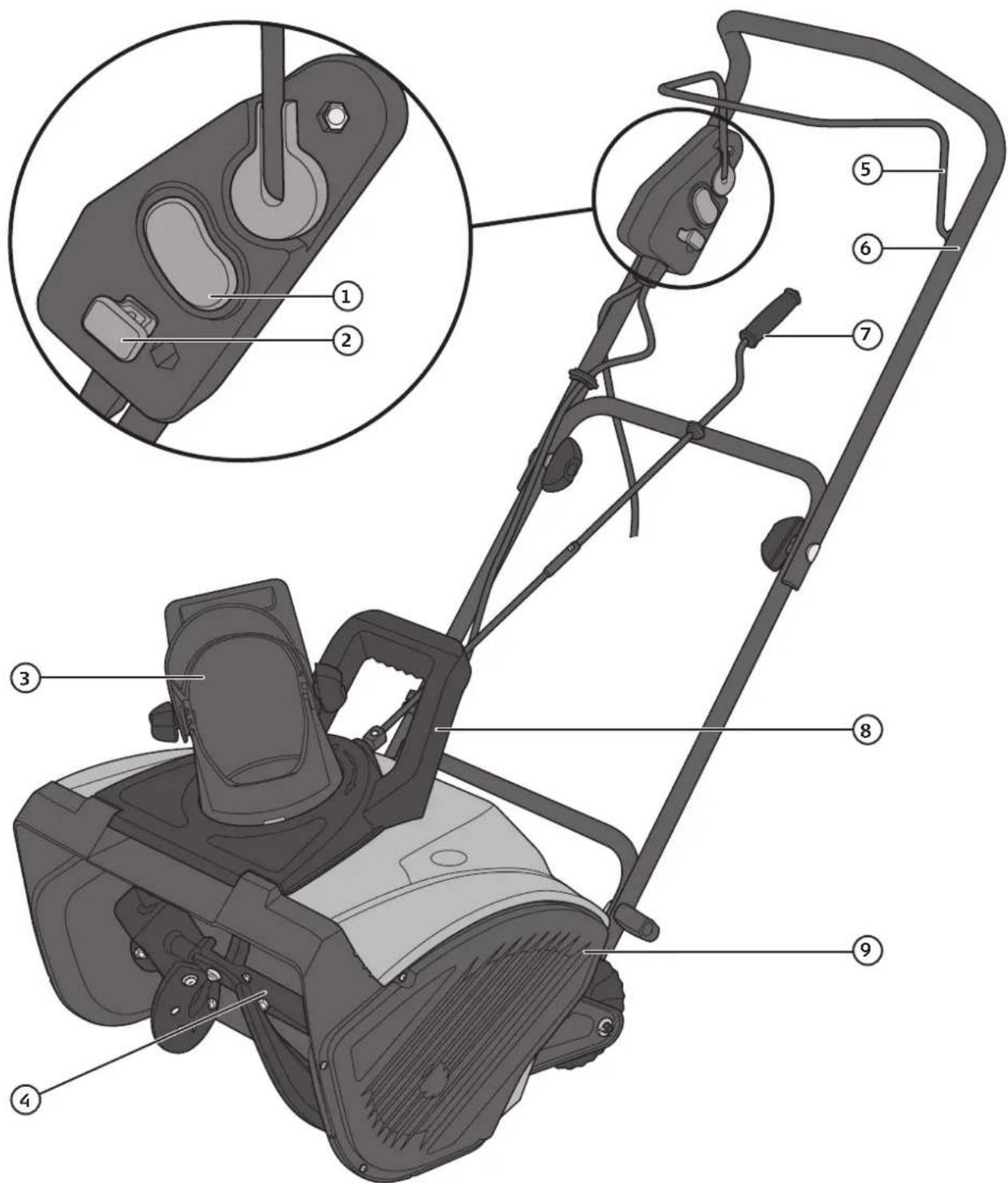
- On/off switch
- Key
- Chute
-
Rubber bladed feed screw
-
Feed screw starting handle
- Handle
- Chute direction crank
- Carrying handle
- Drive belt cover
Assembly
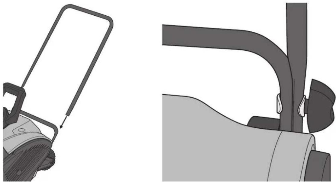
Handle
Join the parts of the handle together using the 4 bolts, wing nuts and washers. If the nuts and bolts were fastened to the handles upon delivery, they will need to be removed first.
natural_image
Technical illustration of a mechanical device with a handle and lever mechanism (no text or symbols)-
Hold the middle part of the handle so that the holes line up with the holes in the lower part. Fasten them together using bolts, washers and wing nuts. The wing nuts should be on the outside of the handle.
-
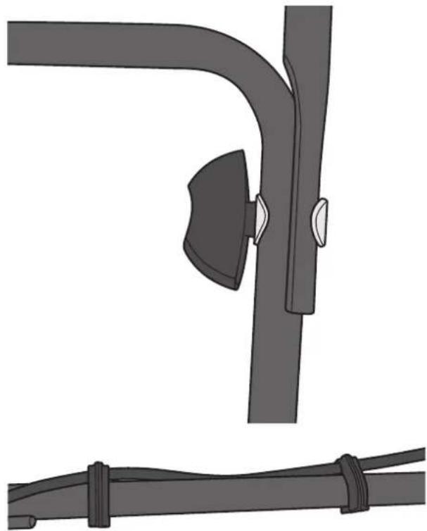
Hold the upper part of the handle so that its holes line up with the holes in the middle part. Fasten them together using bolts, washers and wing nuts. The wing nuts should be on the inside of the handle.
-
Fasten the cable to the handle using two of the included cable clips.
natural_image
Technical illustration of a mechanical linkage assembly with two separate views (top and bottom), no text or symbols present.Chute
natural_image
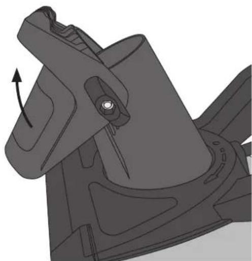
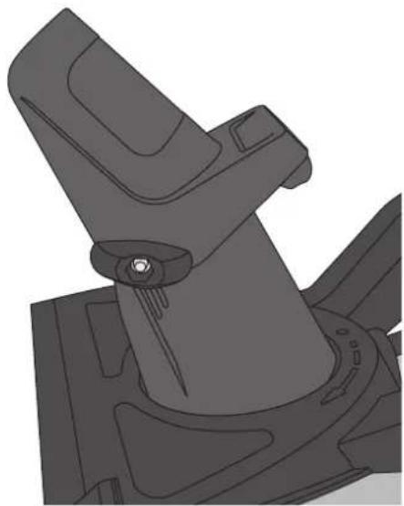
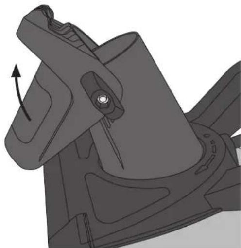
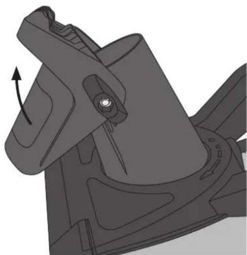
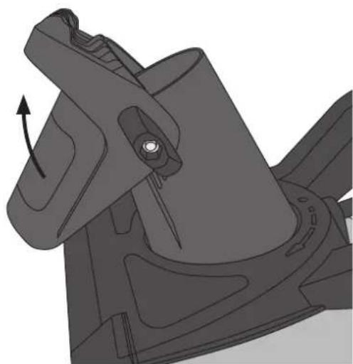
Mechanical component diagram showing a rotating assembly with an arrow indicating rotation (no text or symbols present)- Undo the wing nuts holding the upper part of the chute in place just enough to enable you to lift the top of the chute.
Note: Make sure that there is no gap between the upper part and lower parts of the chute.
natural_image
Mechanical component diagram showing a lever mechanism with mounting flanges and a central hub (no text or symbols)- Set the top of the chute in the desired position and lock it in place using the wing nuts.
Chute direction crank
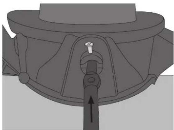
- Slot the two parts of the crank together and fasten using the included nuts and bolts.
natural_image
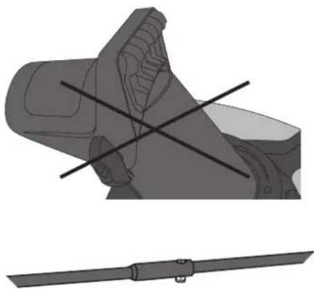
Mechanical component diagram showing a valve inserted into a housing (no text or symbols)- Slot the crank into its hole at the base of the chute and fasten it.
natural_image
Technical illustration of a mechanical component with cross-sectional view and tool holder (no text or symbols)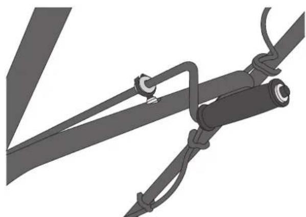
natural_image
Mechanical assembly diagram showing a cable with clamping and mounting bracket (no text or symbols)- Mount the crank's eyelet through the hole in the middle handle and tighten its retaining nut to secure it.
Operation
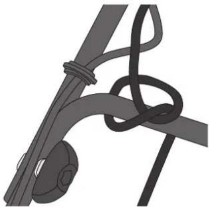
Note: Knot the extension lead loosely around the middle of the handle to prevent it from accidentally disconnecting during operation.
natural_image
Illustration of a rope knot and a hanging object (no text or symbols)Starting
- Make sure that the safety lever for the feed screw drive is released so the blower is in neutral.
- Insert the ignition key. Make sure that it is pushed all the way in.
- Connect an extension lead approved for outdoor use to the mains lead of the snow blower and to an earthed wall socket.
- Press and hold the on/off switch.
- Pull the safety lever in towards the handle to start the feed screw. Release the on/off switch.
- Release the safety lever to stop the feed screw.
Care and maintenance
• Always disconnect the mains lead from the power before servicing or adjusting the snow blower.
- Regularly check that all the nuts and bolts are tight and that the snow blower is undamaged and working properly.
- Ensure that any safety/warning labels are visible and legible. Replace any damaged or illegible labels.
- Always unplug the mains lead after use and before cleaning snow off the feed screw, impeller housing or discharge chute.
- Store the snow blower in a dry, sheltered place out of the reach of children.
- Never store the snow blower with the mains lead plugged into a wall socket.
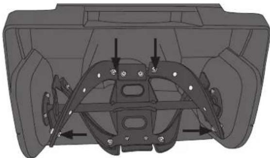
Changing the feed screw blades
- Unplug the mains lead from the wall socket.
- Undo the nuts and bolts and remove the rubber blades.
- Replace the blades with new ones, refit the nuts and bolts and tighten them.
natural_image
Technical diagram of a vehicle dashboard frame with mounting holes and structural components (no text or labels)Replacing the scraper blade
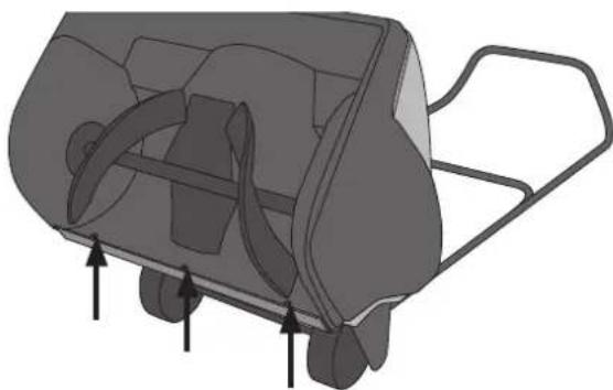
- Unplug the mains lead from the wall socket.
- Lay the snow blower handle down on the ground.
- Detach the worn scraper by removing the 3 screws holding it in place.
- Screw the new scraper into place.
natural_image
3D diagram of a mechanical device with internal components and directional arrows indicating motion (no text or symbols)Changing the Drive Belt
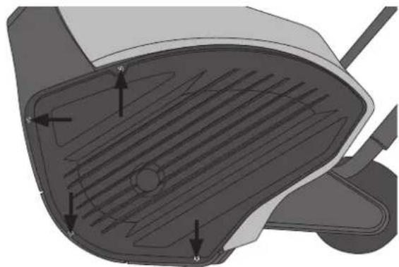
- Unplug the mains lead from the wall socket.
-
Remove the 4 screws from the left side of the belt cover and remove the cover.
-
Lift the belt tensioner and remove the drive belt from the large pulley.
-
Install a new belt as shown in the picture, turning the pulley until the belt sits into its groove.
- Refit the belt cover and the 4 screws.
natural_image
Technical diagram of a vehicle hood with ventilation grating and directional arrows indicating components (no text or labels)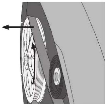
natural_image
Mechanical diagram showing a wheel and gear assembly with directional arrows (no text or symbols)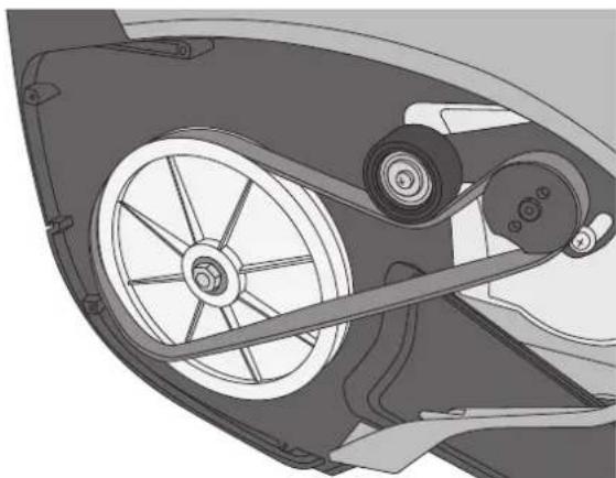
natural_image
Mechanical assembly diagram showing wheel and pulley components (no text or symbols)Troubleshooting guide
| The snow blower does not start. • Make sure that the extension lead is connected correctly.• Check to see if there is power at the wall socket• Is the on/off button pushed in?• Is the safety lever pulled in against the handle? |
| Snow does not exit the chute. • Unplug the extension lead and make sure that the chute is not clogged with snow. |
Responsible disposal
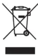
This symbol indicates that this product should not be disposed of with general household waste. This applies throughout the entire EU. In order to prevent any harm to the environment or health hazards caused by incorrect waste disposal, the product must be handed in for recycling so that the material can be disposed of in a responsible manner. When recycling your product, take it to your local collection facility or contact the place of purchase. They will ensure that the product is disposed of in an environmentally sound manner.
Specifications
Rated voltage 230 V, 50 Hz
Wattage 1800 W
No-load speed 2100 rpm
Capacity Max 200 m²/h
Clearing width 46 cm
Max snow depth 25 cm
Discharge range 10 m
LpA 88 dB (A), K = 3.0 dB (A)
LwA 100 dB (A), K = 3.0 dB (A)
Vibration 2.4 m/s², K = 1.5 m/s²
Snöslunga
Art.nr 18-4456 Modell DB5013-UK
31-5053 DB5013
natural_image
Technical illustration of a mechanical device with a handle and lever mechanism (no text or symbols)natural_image
Technical illustration of a mechanical linkage assembly with two views (top and side), no text or symbols present.Utkast
natural_image
Mechanical component diagram showing a rotating arm mechanism (no text or symbols)natural_image
Technical illustration of a mechanical component with no visible text or symbolsnatural_image
Technical illustration of a mechanical component with crosshair lines, no visible text or symbolsVev till utkast
natural_image
Mechanical component diagram showing a lever mechanism with no visible text or symbolsnatural_image
Mechanical assembly diagram showing a cable with attached components (no text or symbols)natural_image
Illustration of a rope knot and a hanging object (no text or symbols)Start
natural_image
3D technical diagram of a car interior showing structural components and mounting points (no text or labels)Byte av skrapskär
natural_image
3D diagram of a mechanical device with internal components and directional arrows indicating motion (no text or symbols)Byte av drivrem
natural_image
Diagram of a car interior showing ventilation grating and exhaust pipe (no text or labels)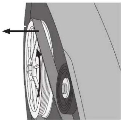
natural_image
Mechanical diagram showing a wheel and pulley assembly with directional arrows (no text or symbols)natural_image
Technical illustration of a car wheel assembly with pulleys and wheels (no text or symbols)Felsökningsschema
LpA 88 dB (A), K = 3.0 dB (A)
LwA 100 dB (A), K = 3.0 dB (A)
Vibration 2.4 m/s ^2 , K = 1.5 m/s ^2
Snøfreser
Art.nr. 18-4456 Modell DB5013-UK
31-5053 DB5013
natural_image
Technical illustration of a mechanical device with a handle and bracket, shown from two different angles (no text or symbols present)natural_image
Technical illustration of a mechanical linkage assembly with two views (top and side), no text or symbols present.Utkast
natural_image
Mechanical component diagram showing a rotating arm mechanism (no text or symbols)natural_image
Technical line drawing of a mechanical component with no visible text or symbolsnatural_image
Mechanical component diagram showing a piston and lever mechanism (no text or symbols)natural_image
Technical illustration of a mechanical component with crosshair lines, no visible text or symbols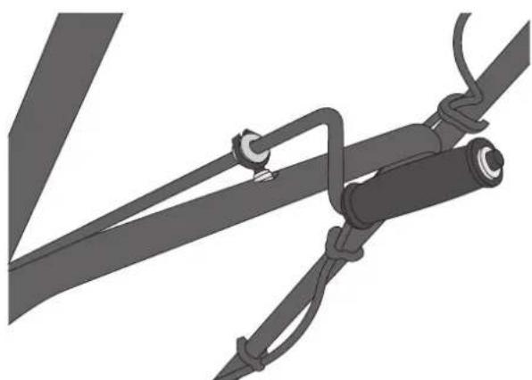
natural_image
Mechanical assembly diagram showing a cable with attached components and connectors (no text or symbols)natural_image
Illustration of a rope knot and a hanging object (no text or symbols)Start
natural_image
Technical diagram of a car interior showing structural components and directional arrows (no text or labels)natural_image
3D diagram of a mechanical device with internal blades and mounting brackets (no text or symbols)Skifte av drivrem
natural_image
Technical diagram of a vehicle hood with internal ventilation grating and labeled components (no text or symbols)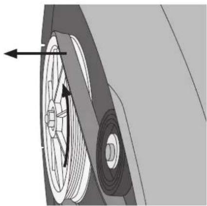
natural_image
Mechanical diagram showing a wheel and pulley assembly with directional arrows (no text or symbols)natural_image
Mechanical assembly diagram showing wheel and pulley components (no text or symbols)Feilsøking
LpA 88 dB (A), K = 3.0 dB (A)
LwA 100 dB (A), K = 3.0 dB (A)
natural_image
Technical illustration of a mechanical device with a handle and side panel view (no text or symbols)natural_image
Technical illustration of a mechanical clamp or bracket assembly with two separate views (no text or symbols)Ulossyöttö
natural_image
Mechanical component diagram showing a rotating assembly with an arrow indicating rotation (no text or symbols present)natural_image
Mechanical component diagram showing a lever mechanism with mounting flanges and a central hub (no text or symbols)natural_image
Technical illustration of a mechanical component with crosshair lines, no visible text or symbolsUlossyötön kampi
natural_image
Mechanical component diagram showing a lever mechanism with no visible text or symbolsnatural_image
Mechanical assembly diagram showing a cable with clamping and mounting bracket (no text or symbols)natural_image
Illustration of a rope knot and hook mechanism (no text or symbols)Käynnistys
natural_image
Technical diagram of a vehicle chassis frame with mounting holes and structural components (no text or labels)natural_image
3D diagram of a mechanical device with internal components and directional arrows indicating motion (no text or symbols)Vetohihnan vaihto
natural_image
3D diagram of a car intake manifold with ventilation grilles and arrows indicating flow direction (no text or symbols)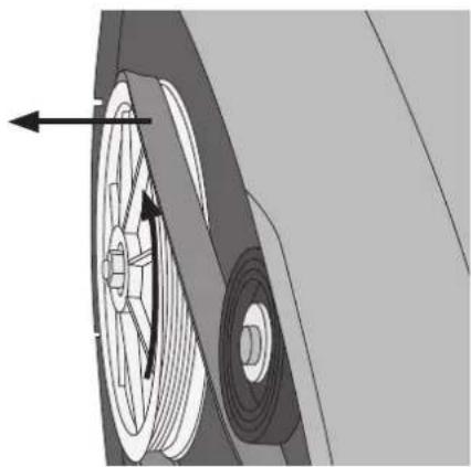
natural_image
Mechanical diagram showing a wheel and gear assembly with directional arrows (no text or symbols)natural_image
Mechanical assembly diagram showing wheel and pulley components (no text or symbols)Vianhakutaulukko
LpA 88 dB (A), K = 3.0 dB (A)
LwA 100 dB (A), K = 3.0 dB (A)
natural_image
Technical illustration of a mechanical device with a handle and bracket, shown from two different angles (no text or symbols present)natural_image
Technical illustration of a mechanical linkage assembly with two views (top and side), no text or symbols present.natural_image
Mechanical component diagram showing a rotating arm mechanism (no text or symbols)natural_image
Mechanical component diagram showing a lever mechanism with mounting flanges and a central hub (no text or symbols)natural_image
Mechanical assembly diagram showing a valve inserted into a housing component (no text or symbols visible)natural_image
Illustration of a mechanical device with intersecting lines, no visible text or symbols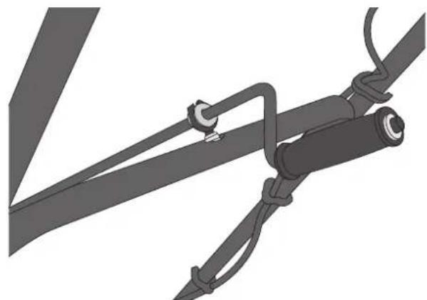
natural_image
Mechanical assembly diagram showing a cable with attached components (no text or symbols)natural_image
Illustration of a rope knot and a hanging object (no text or symbols)Start
natural_image
Technical diagram of a vehicle chassis frame with mounting brackets and structural elements (no text or symbols)natural_image
3D diagram of a mechanical device with internal components and directional arrows indicating motion (no text or symbols)natural_image
Technical diagram of a vehicle hood with internal ventilation grating and labeled components (no text or symbols)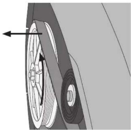
natural_image
Mechanical diagram showing a wheel and gear assembly with directional arrows (no text or symbols)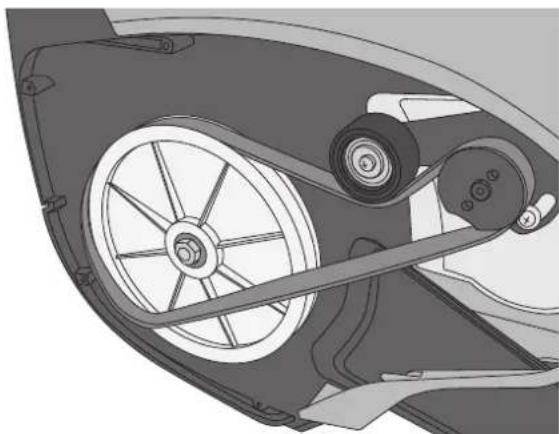
natural_image
Mechanical assembly diagram showing wheel and pulley components (no text or symbols)Fehlersuche
LpA 88 dB (A), K = 3.0 dB (A)
LwA 100 dB (A), K = 3.0 dB (A)
Schwingungsemission 2.4 m/s², K = 1.5 m/s²
Declaration of Conformity
Declares that this product complies with the requirements of the following directives and standards
Henrik Alfredsson
Technical Manager
Insjön, Sweden, 2018-06-13
CLAS OHLSON AB, SE-793 85 INSJÖN, SWEDEN
Sverige
10 - 13 Market Place
Kingston upon Thames
Surrey
KT1 1JZ
Deutschland
Kundenservice
Hotline: 040 2999 78111
E-Mail: kundenservice@clasohlson.de
Homepage
www.clasohlson.de
Postanschrift
- Viktig information:
- Safety
- General safety precautions
- Preparations
- Electrical safety
- Safety precautions during use
- Safety instructions specific to snow blowers
- Contents
- Buttons and functions
- Assembly
- Handle
- Chute
- Chute direction crank
- Operation
- Starting
- Care and maintenance
- Changing the feed screw blades
- Replacing the scraper blade
- Changing the Drive Belt
- Troubleshooting guide
- Responsible disposal
- Specifications
- Snöslunga
- Utkast
- Vev till utkast
- Start
- Byte av skrapskär
- Byte av drivrem
- Felsökningsschema
- Snøfreser
- Skifte av drivrem
- Feilsøking
- Ulossyöttö
- Ulossyötön kampi
- Käynnistys
- Vetohihnan vaihto
- Vianhakutaulukko
- Fehlersuche
- Declaration of Conformity
- Sverige
- Deutschland
Brand : Cocraft
Model : SB46
Category : Snow brushcutter