
SIROCCO700 - Vacuum Cleaner VOX - Free user manual and instructions
Find the device manual for free SIROCCO700 VOX in PDF.


| Product Type | Vacuum Cleaner |
| Brand | VOX |
| Model | SIROCCO700 |
| Power Source | Corded electric |
| Dust Collection Type | Bagged (paper dust bag) |
| Dust Full Indicator | Yes (red indicator light) |
| Inlet Filter | Foam filter (washable) |
| Outlet Filter | HEPA filter (washable) |
| Suction Control | Variable (rotary knob) |
| Cord Rewind | Yes (button-operated) |
| Accessories Included | Metal tube, floor brush, round brush, flat brush |
| Accessory Storage | On-board compartment |
| Applicable Surfaces | Carpets and hard floors (adjustable floor brush) |
| Usage | Indoor household use only |
| Carrying Handle | Yes (on back of unit) |
| Bag Replacement | Easy-open front cover with button |
| Certification | CE |
| Maintenance | Washable filters (dry completely before reinstalling) |
Frequently Asked Questions - SIROCCO700 VOX
User questions about SIROCCO700 VOX
0 question about this device. Answer the ones you know or ask your own.
Ask a new question about this device
Download the instructions for your Vacuum Cleaner in PDF format for free! Find your manual SIROCCO700 - VOX and take your electronic device back in hand. On this page are published all the documents necessary for the use of your device. SIROCCO700 by VOX.
USER MANUAL SIROCCO700 VOX
SCIROCCO 700
OPERATING INSTRUCTIONS VACUUM CLEANERMANUALE DI ISTRUZIONI ASPIRAPOLVEREGEBRAUCHSANLEITUNG STAUBSAUGERИНСТРУКЦИЯ ПО ЭКСПЛУАТАЦИИ ПЫЛЕСОСUPUTSTVO ZA UPOTREBU USISIVAČ
natural_image
Technical line drawing of a mechanical device with no visible text or symbolsSCIROCCO 700
CE

PLEASE READ THIS MANUAL CAREFULLY BEFORE USING AND KEEP IT PROPERLY FOR FUTURE USE
IMPORTANT SAFETY INSTRUCTIONS
Read this manual thoroughly before first use, even if you are familiar with this type of product. The safety precautions enclosed herein reduce the risk of fire, electric shock and injury when correctly adhered to.
Keep the manual in a safe place for future reference, along with the completed warranty card, purchase receipt and carton. If applicable, pass these instructions on to the next owner of the appliance.
Always follow basic safety precautions and accident prevention measures when using an electrical appliance, including the following:
Electrical safety and cord handling
- Before turning on, ensure that your electrical voltage and circuit frequency correspond to those indicated on the appliance.
- To reduce the risk of electrocution, never operate this product or handle the plug with wet hands, submerge it under water or spill liquids into the product.
- Do not insert any objects into the appliance.
- If the supply cord is damaged, it must be replaced by the manufacturer or its service agent or an appropriately qualified person in order to avoid a hazard.
- Check the appliance and cord regularly for visible damage. Do not use it if the cord or housing is damaged, if it has been dropped, damaged, left outdoors or dropped into water, or if it appears faulty in any way. Call the after sales support line if any part appears damaged.
- Do not kink, bend, squash, strain or damage the power cord.
- Do not pull or carry the vacuum cleaner by the cord. Do not use the cord as a handle, close a door on the cord or pull the cord around sharp edges or corners.
Do not run the vacuum cleaner over the cord. Keep the cord away from heated surfaces.
• Turn off the vacuum cleaner controls before connecting or disconnecting it from the mains supply. - WARNING: Always switch off and unplug the vacuum cleaner before connecting or disconnecting the vacuum hose and accessories and before emptying or cleaning the dust tank.
- Do not pull on the cord to disconnect the plug from the power supply. To unplug, grasp the plug, not the cord, and gently pull it out of the power point and then press the cord retraction button to retract the cord.
Usage conditions and restrictions
- This appliance is intended for household use only. It is neither suitable for commercial/industrial nor for outdoor use.
- Only use the vacuum cleaner on dry, indoor surfaces, as described in this manual and with the original accessories supplied by the manufacturer/distributor.
Do not use it for any purpose other than described in this manual. - Improper installation and use may result in the risk of fire, electric shock and/or injury to persons. We assume no liability for any eventual damages caused by improper or faulty use.
- This appliance is not intended for use by persons (including children) with reduced physical, sensory or mental capabilities, or lack of experience and knowledge, unless they have been given supervision or instructions concerning use of the appliance by a person responsible for their safety.
- Supervise young children to ensure they do not play with the appliance. Close supervision is necessary when any appliance is used by or near children.
- Never leave the appliance unattended.
Safe usage
- Keep hair, loose clothing, fingers and all parts of the body away from openings and moving parts.
- Keep the end of the hose, wands and other openings away from your face and body.
- Do not point the vacuum cleaner at people or animals when in use.
- Do not use the product without the filters in place.
• Take extra care when vacuuming on stairs. - Do not use the vacuum cleaner to pick up: flammable or combustible fluids (such as fuel or solvent); burning substances (such ash, cigarettes or hot coals), or use it in the presence of explosive liquids or vapours; hard or sharp objects such as shards of glass, nails, coins; harmful or toxic materials (such as chlorine bleach, ammonia, drain cleaner); any liquids, or vacuum in areas where liquids may be present.
- Keep the vacuum cleaner away from heat sources (radiator, oven etc.), direct sunlight, moisture and sharp edges.
- Keep all openings free of dust, lint, hair or anything that may reduce the airflow.
Do not use the product with any openings blocked or restricted airflow.
- Put the vacuum cleaner away after every use to prevent anyone tripping over it.
- IMPORTANT: Washing the filters improves vacuum performance. Make sure all filters are completely dry before reattaching them.
- Only clean the housing with a soft, dry cloth. Do not use liquid or aerosol cleaners.
- Store the vacuum cleaner indoors in a cool, dry area, out of reach of young children.
- Never attempt to open the motor base of the vacuum cleaner yourself or to replace the power cord. If the vacuum cleaner is damaged, it must be repaired by the manufacturer or its service agent or an appropriately qualified person in order to avoid a hazard. In case of damage, call the after sales support line for advice.
Correct Disposal of this product
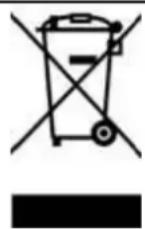
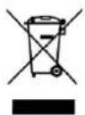
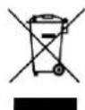
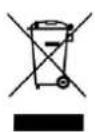
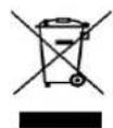
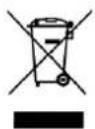
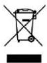
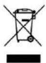
This marking indicates that this product should not be disposed with other household wastes throughout the EU. To prevent possible harm to the environment or human health from uncontrolled waste disposal, recycle it responsibly to promote the sustainable reuse of material resources. To return your used device, please use the return and collection systems or contact the retailer where the product was purchased. They can take this product for environmental safe recycling.
WARNING!
- Never use this machine when the suction power becomes very weak.
When this happens:
- Switch off the unit, unplug it and check whether the dust container is full.
- Then check if any part of the floor brush, tube or hose is blocked.
Do not use the vacuum cleaner until the blockage is removed and it operates normally again.
If you cannot solve the problem, contact the after sales support line.
- Always switch the vacuum cleaner off after use, and before plugging it in again, make sure to hold the vacuum cleaner firmly when using it.
- Always switch off and unplug the vacuum cleaner from the electrical outlet before assembling, opening or emptying the dust bag, or before connecting/ disconnecting the attachments.
PARTS
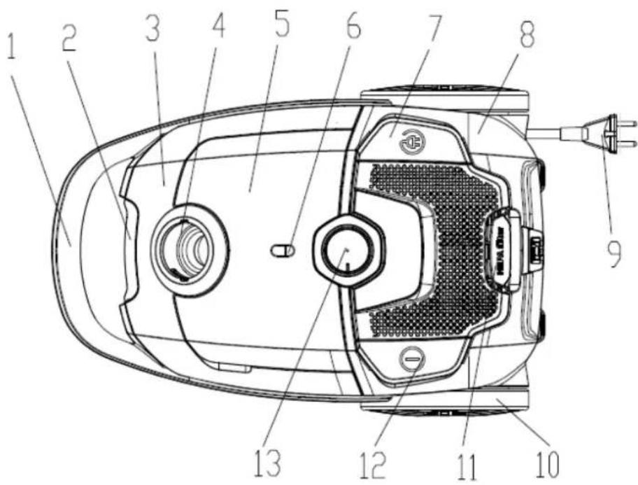
- Handle cover
- Front cover Decorating Plate
- Front cover
- Suction Base
- Accessories Cover
- Dust full indicator
-
Cord Rewinding Button
-
Back Cover
- Power Cord and Plug
- Big Wheel
- Air Outlet Cover
- ON/OFF Switch Button
- Mode Selection knob
Accessory List
A set of hose accessories includes: one metal tube, one floor brush, one round brush, one flat brush.
Operation Method
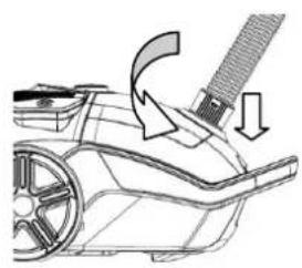
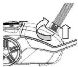
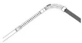
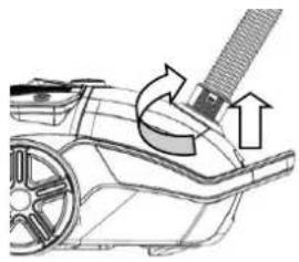
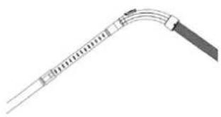
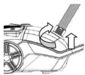
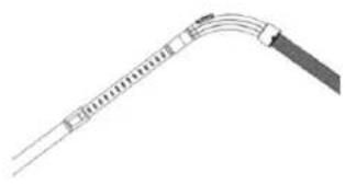
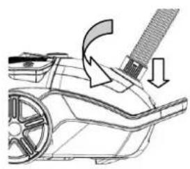
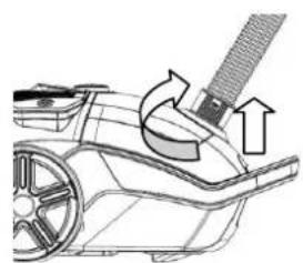
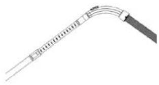
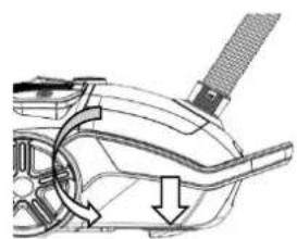
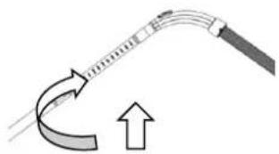
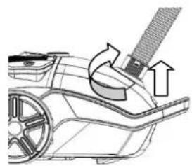
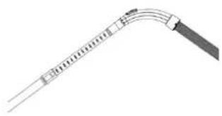
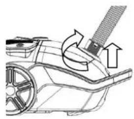
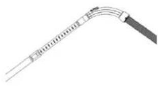
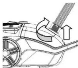
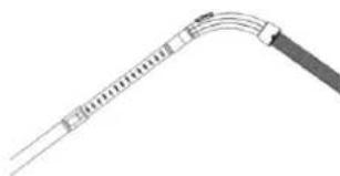
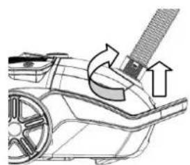
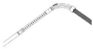
- Connect the hose accessory: insert the hose end into the hose socket at the front cover and then hook it. (Fig 1) Remove the hose accessory: turn the connector of hose to the right position and then pull the hose accessory. (Fig 2), Connect the metal tube to the curved end of the hose. (Fig 3)
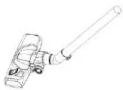
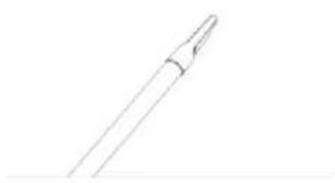
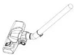
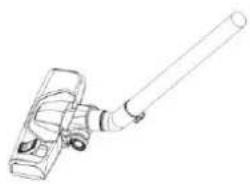
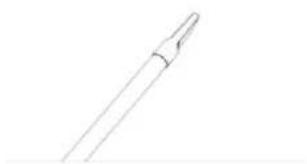
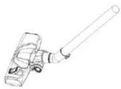
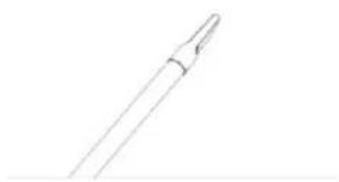
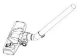
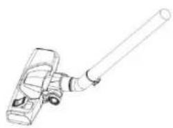
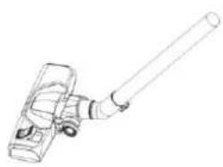
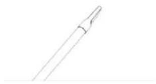
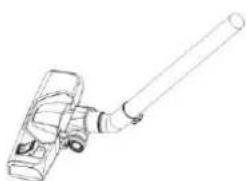
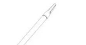
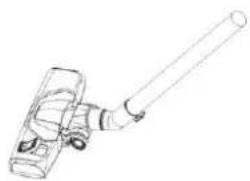
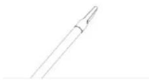
- Connect different nozzle tools to the tube for different cleaning purposes: floor brush (adjusted to the type of ground) for carpet or hard floor (Fig 4); crevice nozzle for sofa, wall surface, curtain, corner of space between furniture, etc. (Fig 5): The round brush and crevice tool is stored in the accessory compartment;
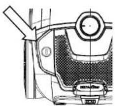
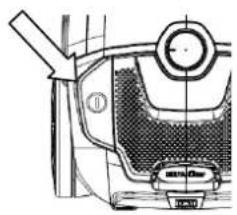
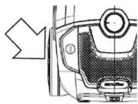
- Operating the vacuum cleaner: insert the plug and cord into the power socket which conforms to that on the label for the power supply, and press the on/off switch pedal, the vacuum cleaner will start working. (Fig 6)
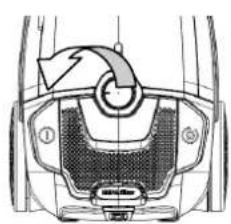
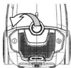
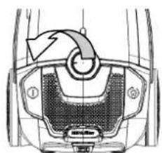
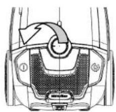
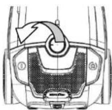
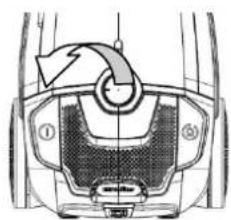
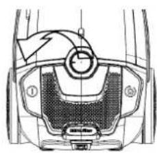
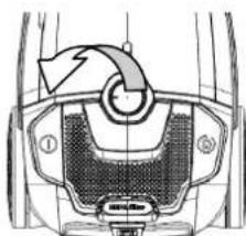
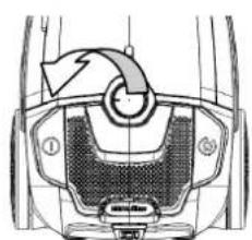
- Adjust the power of the vacuum power: changing the power of the machine by the right and left rotation speed control knob to meet the different needs of use (Fig 7).
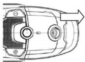
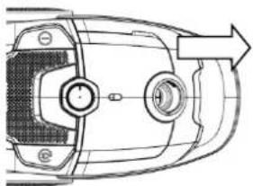
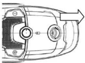
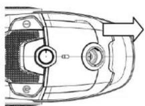
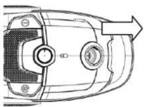
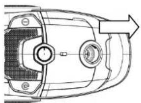
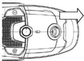
- Move the machine: carry the handle at the back of vacuum (Fig 8).
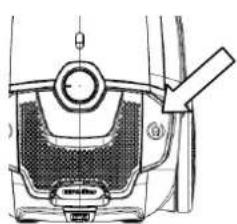
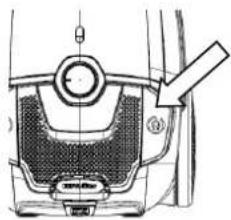
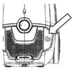
- Cord rewinding: Switch off the vacuum cleaner with on/off switch button and pull the plug from the main socket, press the cord rewinding button, the power cord will be drawn in (Fig 9).
natural_image
Technical line drawing of a car interior showing a lever and handle mechanism (no text or symbols)Fig 1
natural_image
Technical line drawing of a car interior showing steering wheel, gear shift, and directional arrows (no text or symbols)Fig 2
natural_image
Pure diagram of a curved mechanical or electrical component without any text, numbers, or symbolsFig 3
natural_image
Line drawing of a mechanical device with a cylindrical rod extending from its side (no text or symbols)Fig 4
natural_image
Simple line drawing of a pen or stylus (no text or symbols)Fig 5
natural_image
Technical line drawing of a mechanical component with no visible text or symbolsFig 6
natural_image
Technical diagram of a mechanical component with labeled parts (no readable text or symbols)Fig 7
natural_image
Technical line drawing of a car interior with directional arrow indicating movement (no text or symbols)Fig 8
natural_image
Technical line drawing of a mechanical component with no visible text or symbolsFig 9
Maintenance
-
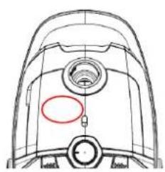
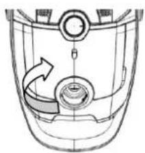
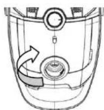
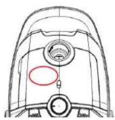
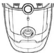
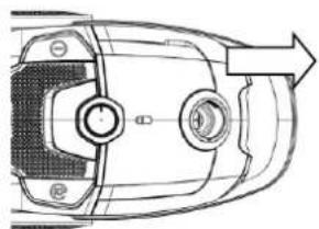
Change the dust bag: when the dust full indicator turns red or loss of suction is noticed, it is time to clear the dust bag or replace with a new bag. (Fig 10)
-
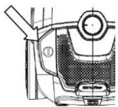
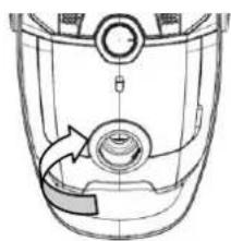
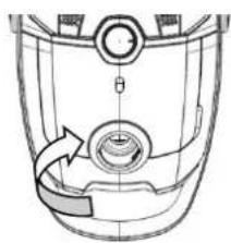
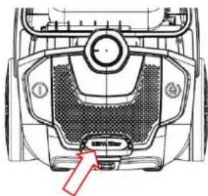
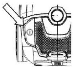
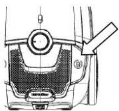
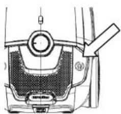
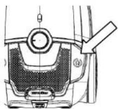
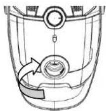
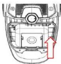
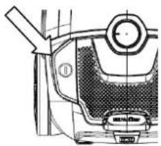
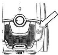
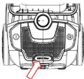
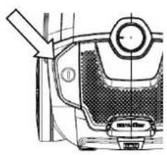
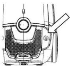
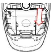
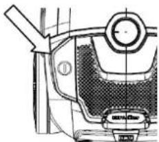
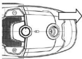
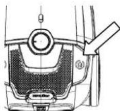
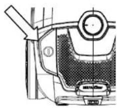
Open the front cover by touching front cover button. (Fig 11)
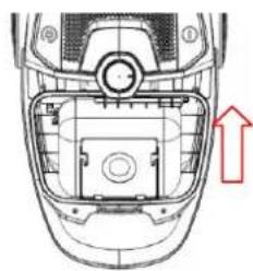
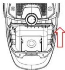
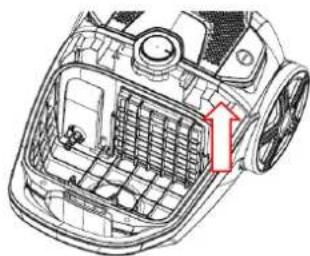
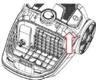
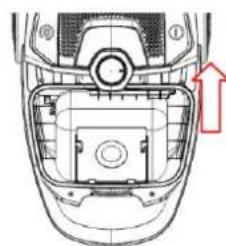
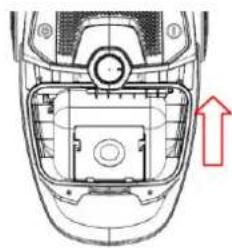
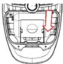
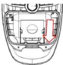
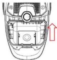
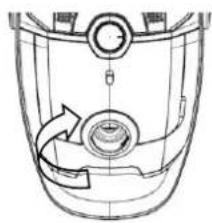
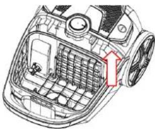
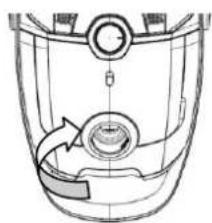
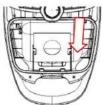
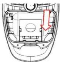
● Take out the bag holder then remove the full dust bag. (Fig 12)
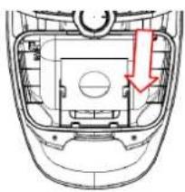
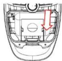
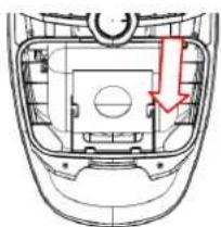
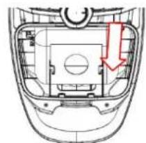
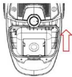
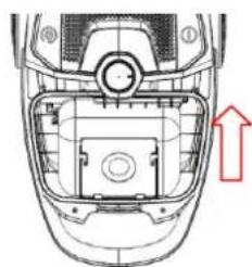
Installing the dust bag: insert the dust bag into the bag holder and then put it in the slot cabinet. (Fig 13) Note: If the dust bag is not installed, the front cover can't be closed
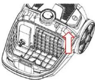
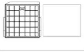
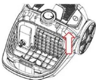
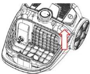
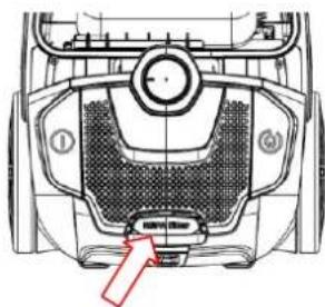
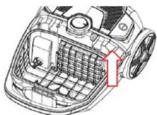
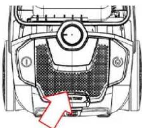
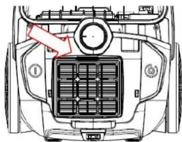
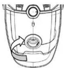
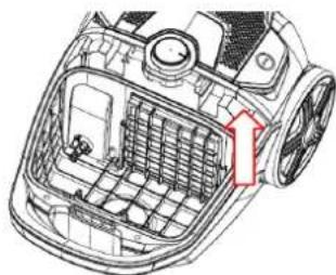
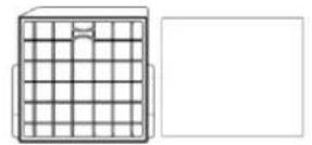
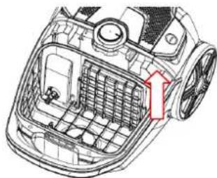
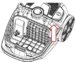
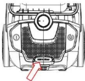
- Inlet filter: clean the filter with warm water and allow to dry fully before placing back into the unit. (Fig 14) Replacing the inlet filter: clip down and remove the inlet cover, remove and replace with a suitable filter. (Fig 15)
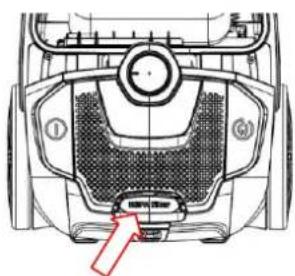
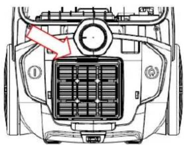
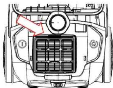
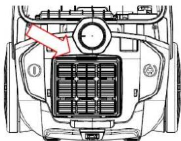
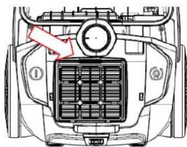
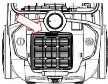
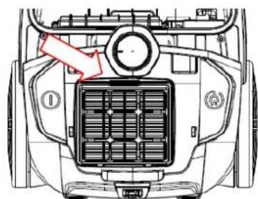
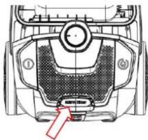
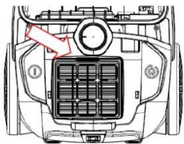
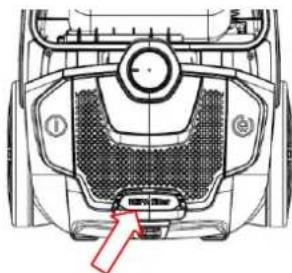
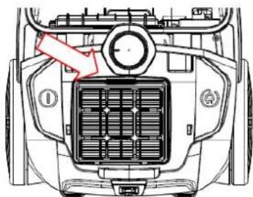
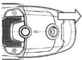
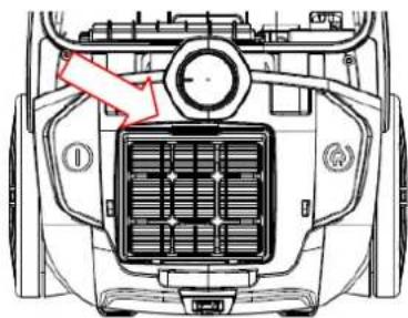
- Clean the outlet filter: open the outlet cover and take out the HEPA frame and filter. Wash it and install it after the filter has fully dried. (Fig 16/17)
natural_image
Technical line drawing of a mechanical component with no visible text or symbolsFig 10
natural_image
Technical line drawing of a mechanical component with no visible text or symbolsFig 11
natural_image
Top-down technical diagram of a vehicle head with internal components and a red arrow indicating direction (no text or symbols)Fig 12
natural_image
Technical diagram of a vehicle head and dashboard with no visible text or symbolsFig 13
natural_image
Technical diagram of a car interior showing internal compartments and fan structure (no text or labels)Fig 14
natural_image
Simple line drawing of a grid-patterned object next to a blank rectangular area (no text or symbols)Fig 15
natural_image
Technical line drawing of a mechanical component with no visible text or symbolsFig 16
natural_image
Top-down technical diagram of a vehicle's front engine compartment showing internal air vent and control panel (no text or labels)Fig 17
Warning
The plug must be removed from the power socket before any maintenance or replacement.
If the power cord is damaged, it must be replaced by the manufacturer or its service agent or an appropriately qualified person in order to avoid a hazard.
natural_image
Technical line drawing of a mechanical device with no visible text or symbolsSCIROCCO 700
CE

LEGGERE CON ATTENZIONE QUESTO MANUALE PRIMA DI UTILIZZARE L'UNITÀ E CONSERVARE PER USO FUTURO.
IMPORTANTI ISTRUZIONI DI SICUREZZA
natural_image
Mechanical diagram showing a tool interacting with a car's wheel and dashboard (no text or symbols)Fig 1
natural_image
Technical line drawing of a car interior showing a handle and seat assembly (no text or symbols)Fig 2
natural_image
Pure diagram of a curved mechanical or electrical component without any text, numbers, or symbolsFig 3
natural_image
Line drawing of a mechanical lever or clamp device (no text or symbols)Fig 4
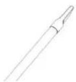
Fig 5
natural_image
Technical line drawing of a mechanical component with no visible text or symbolsFig 6
natural_image
Diagram of a mechanical component with labeled parts and directional arrow (no text or symbols)Fig 7
natural_image
Top-down schematic of a vehicle dashboard with control buttons and an arrow indicating direction (no text or symbols)Fig 8
natural_image
Technical line drawing of a mechanical component with a highlighted section (no text or symbols)Fig 9
Manutenzione
natural_image
Technical line drawing of a mechanical component with no visible text or symbolsFig 10
natural_image
Technical line drawing of a mechanical component with no visible text or symbolsFig 11
natural_image
Top-down view of a car's front intake showing internal components and a red arrow indicating direction (no text or symbols)Fig 12
natural_image
Technical diagram of a vehicle head with internal components and a red arrow indicating a specific area (no text or symbols present)Fig 13
natural_image
Technical line drawing of a car air vent with internal compartments and a red arrow indicating a component (no text or symbols present)Fig 14

Fig 15
natural_image
Top-down technical diagram of a mechanical component with labeled parts (no readable text or symbols)Fig 16
natural_image
Top-down technical diagram of a vehicle's front engine compartment showing vent, grille, and mounting points (no text or labels)Fig 17
Avvertimento
natural_image
Technical line drawing of a mechanical device with no visible text or symbolsSCIROCCO 700
CE

natural_image
Mechanical diagram showing a curved arrow interacting with a component, no text or symbols presentAbb. 1
natural_image
Technical line drawing of a car hood with a brush and directional arrows indicating motion (no text or symbols)Abb. 2
natural_image
Pure diagram of a curved mechanical or electrical component without any text, numbers, or symbolsAbb. 3
natural_image
Line drawing of a mechanical device with a cylindrical rod and lever (no text or symbols)Abb. 4
natural_image
Simple line drawing of a pen or stylus (no text or symbols)Abb. 5
natural_image
Technical line drawing of a mechanical component with no visible text or symbolsAbb. 6
natural_image
Technical diagram of a mechanical component with labeled parts (①, ②, ③) and directional arrow indicating rotation or force (no text or symbols beyond labels)Abb. 7
natural_image
Technical line drawing of a car's top-down view showing front and side views with no text or symbolsAbb. 8
natural_image
Technical line drawing of a mechanical component with no visible text or symbolsAbb.9
Wartung
natural_image
Top-down schematic of a vehicle's front view showing dashboard, gear, and wheel (no text or labels)Abb. 10
natural_image
Technical line drawing of a mechanical component with no visible text or symbolsAbb. 11

natural_image
Technical diagram of a car's front and side views showing engine, dashboard, and gear components (no text or labels)Abb. 12
natural_image
Technical diagram of a vehicle head panel with no visible text or symbolsAbb. 13
natural_image
Technical line drawing of a car interior showing internal compartments and a red arrow indicating a specific area (no text or symbols present)Abb. 14
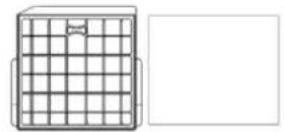
Abb. 15
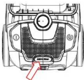
Abb. 16
natural_image
Top-down technical diagram of a vehicle's front engine compartment showing vent, grille, and dashboard (no text or labels)Abb. 17
Warnung
natural_image
Technical line drawing of a mechanical device with no visible text or symbolsSCIROCCO 700
CE

natural_image
Diagram of a car interior showing steering wheel, dashboard, and gear shift (no text or labels)natural_image
Technical line drawing of a car interior showing a brush and directional arrows indicating motion (no text or symbols)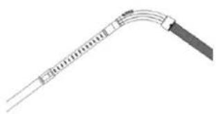
natural_image
Pure diagram of a curved mechanical or electrical component without any text, numbers, or symbols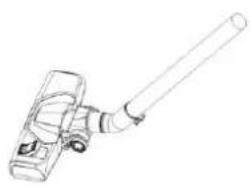
natural_image
Line drawing of a mechanical device with a cylindrical shaft and lever (no text or symbols)natural_image
Simple line drawing of a pen or stylus (no text or symbols)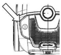
natural_image
Technical line drawing of a mechanical component with no visible text or symbols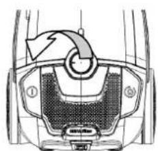
natural_image
Technical diagram of a mechanical component with labeled parts (no readable text or symbols)Рис. 7.
natural_image
Top-down schematic of a car's front wheel and dashboard (no text or symbols)Рис. 8.
natural_image
Technical line drawing of a mechanical component with no visible text or symbolsРис. 9.
natural_image
Technical line drawing of a mechanical component with no visible text or symbolsРис. 10.
Рис. 11.
natural_image
Technical line drawing of a mechanical component with an arrow indicating rotation (no text or symbols)Рис. 12.
natural_image
Top-down technical diagram of a car's front and head assembly, showing internal components and a red arrow indicating direction (no text or labels)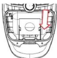
natural_image
Technical diagram of a vehicle head panel with no visible text or symbolsРис. 13.
Рис. 14.
natural_image
Technical diagram of a car air vent with internal compartments and a red arrow indicating direction (no text or symbols)Рис. 15.

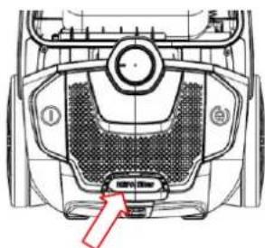
Рис. 16.
Рис. 17.
natural_image
Top-down technical diagram of a vehicle's front engine compartment showing vent, grille, and mounting points (no text or labels)Предупреждение
natural_image
Technical line drawing of a mechanical device with no visible text or symbolsSCIROCCO 700
CE

VAŽNA BEZBEDNOSNA UPUTSTVA
Pročitajte ovo uputstvo pre prve upotrebe, čak iako ste upoznati sa ovom vrstom proizvoda. Ovde navedene sigurnosne mere opreza smanjuju rizik od požara, strujnog udara i povreda ako ih se pravilno pridržavate.
- Ručka
- Dekorativna ploča na prednjem poklopcu
- Prednji poklopac
- Usisna baza
- Poklopac za dodatke
- Indikator prepunjenosti kese za prašinu
- Dugme za namotavanje kabla
-
Zadnji poklopac
-
Kabl i utikač
- Veliki točak
- Poklopac za odvod vazduha
- ON/OFF Dugme za uključivanje/ isključivanje
- Regulator izbora režima rada
Spisak dodataka
U set dodataka za crevo spadaju: jedna metalna cev, jedna četka za pod, jedna okrugla četka, jedna ravna četka.
Način rada
- Stavite dodatak creva: umetnite kraj creva u otvor za crevo na prednjem poklopcu, a zatim ga pričvrstite. (Sl.1) Sklonite dodatak creva: priključak creva okrenite u pravilan položaj, a zatim povucite dodatak creva. (Sl. 2), Stavite metalnu cev na zakrivljeni kraj creva. (Sl. 3)
- Stavljajte različite četke i dodatke na cev za različite namene čišćenja: četka za pod (prilagođena vrsti poda) za tepih ili tvrdi pod (Sl.4); usisni dodatak za sofu, zidne površine, zavese, uglove između nameštaja i sl. (Sl. 5);
Okrugla četka i usisni dodatak nalaze se u pregradi za dodatke.
- Rukovanje usisivačem: uključite utikač kabla u utičnicu koja je u skladu s onom na etiketi za napajanje i pritisnite papučicu za uključivanje / isključivanje i usisivač će početi da radi. (Sl. 6).
- Podešavanje snage usisavanja: okretanjem indikatora režima rada u levo ili u desno, pronađite odgovarajući način rada. (Sl. 7).
- Pomeranje uređaja: držite ručku na zadnjem delu uređaja radi pomeranja (Sl. 8).
- Namotavanje kabla: Isključite usisivač pritiskom na dugme za uključivanje / isključivanje i isključite utikač iz utičnice, pritisnite dugme za namotavanje kabla i kabl će se uvući (Sl. 9).
natural_image
Technical line drawing of a mechanical component with an arrow indicating motion or assembly (no text or symbols)Slika 1
natural_image
Technical line drawing of a car's hood and seat assembly (no text or symbols)Slika 2
natural_image
Pure diagram of a curved mechanical or electrical component without any text, numbers, or symbolsSlika 3
natural_image
Line drawing of a mechanical device with a cylindrical shaft and attached housing (no text or symbols)Slika 4
natural_image
Simple line drawing of a pen or stylus (no text or symbols)Slika 5
natural_image
Technical line drawing of a mechanical component with no visible text or symbolsSlika 6
natural_image
Technical diagram of a mechanical component with labeled parts (no readable text or symbols)Slika 7
natural_image
Top-down schematic of a vehicle's front wheel and dashboard (no text or symbols)Slika 8
natural_image
Technical line drawing of a mechanical component with no visible text or symbolsSlika 9
Održavanje
-
Menjanje kese za prašinu: kada indikator prepunjenosti kese za prašinu zasvetli crveno ili primetite loše usisavanje, vreme je da očistite kesu za prašinu ili je zamenite novom. (Sl.10)
-
Otvorite prednji poklopac dodirom na dugme prednjeg poklopca. (Sl.11)
- Izvadite držač kese za prašinu, a zatim sklonite punu kesu za prašinu. (Sl.12)
Stavljanje kese za prašinu: umetnite kesu za prašinu u držač kese za prašinu, a zatim je stavite u pregradu. (Sl.13)
Napomena: Ako kesa za prašinu nije stavljena, prednji poklopac se ne može zatvoriti.
- Ulazni filter: očistite filter toplom vodom i ostavite da se potpuno osuši pre nego što ga vratite u uređaj. (Sl.14) Zamena ulaznog filtera: otvorite i sklonite poklopac, sklonite stari filter i zamenite odgovarajućim filterom. (Sl. 15)
- Čišćenje izlaznog filtera: otvorite izlazni poklopac i izvadite HEPA okvir i filter. Operite i stavite filter tek nakon što se potpuno osuši. (Sl. 16/17)
natural_image
Technical line drawing of a mechanical component with no visible text or symbolsSlika 10
natural_image
Technical line drawing of a mechanical component with no visible text or symbolsSlika 11
natural_image
Top-down technical diagram of a vehicle head and engine compartment with no visible text or symbolsSlika 12
natural_image
Technical line drawing of a car interior showing dashboard and seat components with no visible text or symbolsSlika 13
natural_image
Technical diagram of a car air intake manifold showing internal compartments and fan structure (no text or labels)Slika 14

Slika 15
natural_image
Top-down technical diagram of a mechanical component with labeled parts (no readable text or symbols)Slika 16
natural_image
Top-down technical diagram of a vehicle's front engine compartment showing air vent and fan structure (no text or symbols)Slika 17
Upozorenje
Pre bilo kakvog održavanja ili zamene, utikač treba isključiti iz utičnice. Ako je kabl za napajanje oštećen, mora ga zameniti proizvođač ili njegov servisni agent ili odgovarajuće kvalifikovana osoba kako bi se izbegla opasnost.
natural_image
Technical line drawing of a mechanical device with no visible text or symbolsSCIROCCO 700
CE

POR FAVOR, LEA ESTE MANUAL ATENTEMENTE ANTES DE USAR EL APARATO, Y GUARDELO PARA FUTURAS REFERENCIAS
natural_image
Technical line drawing of a car interior component with handle and wheel (no text or symbols)Fig 1
natural_image
Technical diagram of a mechanical component with a curved arrow indicating direction (no text or symbols present)Fig 2
natural_image
Diagram showing a curved arrow with an upward arrow, no text or symbols presentFig 3
natural_image
Line drawing of a mechanical device with a cylindrical rod extending upward (no text or symbols)Fig 4
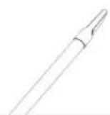
Fig 5
natural_image
Technical line drawing of a vehicle front panel with a circular head and gear (no text or symbols)Fig 6
natural_image
Diagram of a car interior showing a seatbelt with a directional arrow indicating rotation (no text or symbols)Fig 7
natural_image
Technical line drawing of a car's top-down view showing front wheel, side-mounted buttons, and dashboard (no text or symbols)Fig 8
natural_image
Technical line drawing of a mechanical component with a central hub and a handle (no text or symbols)Fig 9
Mantenimiento
natural_image
Technical line drawing of a mechanical component with no visible text or symbolsFig 10

natural_image
Technical line drawing of a mechanical component with no visible text or symbolsFig 11
natural_image
Top-down schematic of a vehicle head showing internal components and a red arrow indicating direction (no text or symbols)Fig 12
natural_image
Technical line drawing of a vehicle head panel with no visible text or symbolsFig 13
natural_image
Technical line drawing of a car interior showing internal compartments and structural elements (no text or labels)Fig 14

Fig 15
natural_image
Technical diagram of a vehicle's front view showing dashboard, intake manifold, and gear (no text or labels)Fig 16
natural_image
Top-down technical diagram of a vehicle's front engine compartment showing vent, grille, and mounting points (no text or labels)Fig 17
¡ADVERTENCIA!
natural_image
Technical line drawing of a mechanical device with no visible text or symbolsSCIROCCO 700

POR FAVOR LEIA ATENTAMENTE ESTE MANUAL E MANTENHA-O PARA NECESSIDADES FUTURAS
INSTRUÇÕES DE SEGURANÇA A TER EM CONTA
natural_image
Diagram of a car dashboard with a tool and directional arrows indicating motion (no text or symbols)Fig 1
natural_image
Diagram of a car interior showing a lever and handle mechanism (no text or symbols)Fig 2
natural_image
Pure diagram of a curved mechanical or electrical component without any text, numbers, or symbolsFig 3
natural_image
Line drawing of a mechanical lever or lever device with a cylindrical shaft and handle (no text or symbols)Fig 4
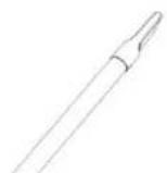
Fig 5
natural_image
Technical line drawing of a mechanical component with no visible text or symbolsFig 6
natural_image
Technical diagram of a mechanical component with labeled parts (①, ②, ③) and an arrow indicating rotation or force direction (no text or symbols beyond labels)Fig 7
natural_image
Top-down schematic of a vehicle's front wheel and dashboard (no text or symbols)Fig 8
natural_image
Technical line drawing of a mechanical device with a handle and internal components (no text or symbols)Fig 9
Manutenção
natural_image
Technical line drawing of a mechanical component with no visible text or symbolsFig 10
natural_image
Technical line drawing of a mechanical component with no visible text or symbolsFig 11
natural_image
Technical diagram of a mechanical component with no visible text or symbolsFig 12
natural_image
Technical diagram of a vehicle head with internal components and a red arrow indicating a specific area (no text or symbols present)Fig 13
natural_image
Technical line drawing of a car interior showing internal compartments and fan structure (no text or symbols)Fig 14

Fig 15
natural_image
Top-down technical diagram of a vehicle's engine compartment, showing mesh head and circular components (no text or labels)Fig 16
natural_image
Top-down technical diagram of a vehicle's front engine compartment showing vent, grille, and gear (no text or labels)Fig 17
Aviso
natural_image
Technical line drawing of a mechanical device with no visible text or symbolsSCIROCCO 700
CE

natural_image
Technical line drawing of a car interior showing a brush applying material to the dashboard (no text or symbols)Eik 1
natural_image
Technical line drawing of a mechanical component with arrows indicating motion or assembly (no text or symbols)Eik 2
natural_image
Pure diagram of a curved mechanical or electrical component without any text, numbers, or symbolsEik 3
natural_image
Line drawing of a mechanical device with a long rod and lever (no text or symbols)Eik 4
natural_image
Simple line drawing of a pen or stylus (no text or symbols)Eik 5
natural_image
Technical line drawing of a mechanical component with no visible text or symbolsEik 6
natural_image
Technical diagram of a mechanical component with labeled parts (no readable text or symbols)Eik 7
natural_image
Top-down schematic of a vehicle's top-down view showing key components and airflow direction (no text or labels)Eik 8
natural_image
Technical line drawing of a mechanical component with no visible text or symbolsEik 9
Συντήριση
natural_image
Top-down technical diagram of a vehicle's rear intake and dashboard (no text or labels)Eik 10
natural_image
Technical line drawing of a mechanical component with an arrow indicating rotation or movement (no text or symbols)Eik 11
natural_image
Top-down technical diagram of a vehicle head and dashboard with no visible text or symbolsEik 12
natural_image
Technical line drawing of a vehicle head panel with no visible text or symbolsEik 13
natural_image
Technical diagram of a car interior showing internal compartments and a red arrow indicating a specific area (no text or symbols present)Eik 14
Eik 15
natural_image
Top-down technical diagram of a mechanical component with labeled parts (no readable text or symbols)Eik 16
natural_image
Top-down technical diagram of a vehicle's front engine compartment showing internal grid structure and mounting points (no text or labels)Eik 17
Προειδοποιήση
natural_image
Technical line drawing of a mechanical device with no visible text or symbolsSCIROCCO 700
CE

PRED UPORABO POZORNO PREUČITE NAVODILA. SHRANITE TA NAVODILA ZA POZNEJŠO UPORABO.
POMEMBNI VARNOSTNI NAPOTKI
natural_image
Simple line drawing of a trash bin with crossed lines indicating no waste or discharge (no text or symbols)natural_image
Diagram of a car interior showing a curved arrow and a downward arrow indicating motion or change (no text or symbols present)Slika 1
natural_image
Diagram of a car interior showing a brush applying force to a wheel rim, with no text or symbols present.Slika 2
natural_image
Pure diagram of a curved pipe or tube with internal divisions, no text or symbols presentSlika 3
natural_image
Line drawing of a mechanical lever assembly (no text or symbols)Slika 4
natural_image
Simple line drawing of a pen or pipette (no text or symbols)Slika 5
natural_image
Technical line drawing of a mechanical component with no visible text or symbolsSlika 6
natural_image
Technical diagram of a mechanical component with no visible text or symbolsSlika 7
natural_image
Technical line drawing of a vehicle head and dashboard with no visible text or symbolsSlika 8
natural_image
Technical line drawing of a mechanical component with no visible text or symbolsSlika 9
Vzdrževanje
natural_image
Technical line drawing of a mechanical component with no visible text or symbolsSlika 10
natural_image
Technical line drawing of a mechanical component with an arrow indicating rotation or assembly (no text or symbols)Slika 11
natural_image
Top-down technical diagram of a vehicle head and engine compartment with no visible text or symbolsSlika 12
natural_image
Technical diagram of a vehicle head with internal components and a red arrow indicating a specific area (no text or symbols present)Slika 13
natural_image
Technical diagram of a car air intake manifold with no visible text or symbolsSlika 14

Slika 15
Slika 16
natural_image
Top-down technical diagram of a vehicle's front engine compartment showing vent, grille, and mounting points (no text or labels)Slika 17
Pozor
natural_image
Technical line drawing of a mechanical device with no visible text or symbolsSCIROCCO 700
CE

POZORNO PROČITAJTE OVE UPUTE PRIJE KORIŠTENJA I SAČUVAJTE IH ZA BUDUĆU UPORABU
VAŽNE SIGURNOSNE UPUTE
natural_image
Technical line drawing of a mechanical component with an arrow indicating motion or assembly (no text or symbols)Slika 1
natural_image
Technical line drawing of a car's hood and seat assembly (no text or symbols)Slika 2
natural_image
Pure diagram of a curved mechanical or electrical component without any text, numbers, or symbolsSlika 3
natural_image
Line drawing of a handheld device with a cylindrical handle and mechanical components (no text or symbols)Slika 4
natural_image
Simple line drawing of a pen or stylus (no text or symbols)Slika 5
natural_image
Technical line drawing of a mechanical component with no visible text or symbolsSlika 6
natural_image
Technical diagram of a mechanical component with labeled parts (no readable text or symbols)Slika 7
natural_image
Top-down schematic of a car's front wheel and dashboard (no text or symbols)Slika 8
natural_image
Technical line drawing of a mechanical component with no visible text or symbolsSlika 9
Održavanje
-
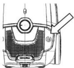
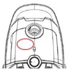
Mijenjanje vreće za prašinu: kada indikator prepunjenosti vreće za prašinu zasvijetli crveno ili primjetite loše usisavanje, vrijeme je da očistite vreću za prašinu ili je zamijenite novom. (Sl.10)
-
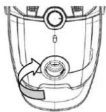
Otvorite prednji poklopac dodirom na gumb prednjeg poklopca. (Sl.11)
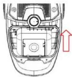
- Izvadite držač vreće za prašinu, a zatim sklonite punu vreću za prašinu. (Sl.12)
Stavljanje vreće za prašinu: umjetnite vreću za prašinu u držač vreće za prašinu, a zatim je stavite u pregradu. (Sl.13)
Napomena: Ako vreća za prašinu nije stavljena, prednji poklopac se ne može zatvoriti.
- Ulazni filter: očistite filter toplom vodom i ostavite da se potpuno osuši prije nego što ga vratite u uređaj. (Sl.14) Zamjena ulaznog filtra: otvorite i sklonite poklopac, sklonite stari filter i zamijenite odgovarajućim filtrom. (Sl. 15)
- Čišćenje izlaznog filtra: otvorite izlazni poklopac i izvadite HEPA ram i filter. Operite i stavite filter tek nakon što se potpuno osuši. (Sl. 16/17)
natural_image
Technical line drawing of a mechanical component with no visible text or symbolsSlika 10
natural_image
Technical line drawing of a mechanical component with no visible text or symbolsSlika 11
natural_image
Top-down technical diagram of a vehicle head and engine compartment with no visible text or symbolsSlika 12
natural_image
Technical line drawing of a car interior showing dashboard and seat components with no visible text or symbolsSlika 13
natural_image
Technical diagram of a car air intake manifold showing internal compartments and fan structure (no text or labels)Slika 14

Slika 15
natural_image
Top-down technical diagram of a mechanical component with labeled parts (no readable text or symbols)Slika 16
natural_image
Top-down technical diagram of a vehicle's front engine compartment showing air vent and fan structure (no text or symbols)Slika 17
Upozorenje
- SCIROCCO 700
- IMPORTANT SAFETY INSTRUCTIONS
- Electrical safety and cord handling
- Usage conditions and restrictions
- Safe usage
- Correct Disposal of this product
- WARNING!
- PARTS
- Accessory List
- Operation Method
- Maintenance
- Warning
- IMPORTANTI ISTRUZIONI DI SICUREZZA
- Manutenzione
- Avvertimento
- Wartung
- Warnung
- Предупреждение
- VAŽNA BEZBEDNOSNA UPUTSTVA
- Spisak dodataka
- Način rada
- Održavanje
- Upozorenje
- Mantenimiento
- ¡ADVERTENCIA!
- INSTRUÇÕES DE SEGURANÇA A TER EM CONTA
- Manutenção
- Aviso
- Συντήριση
- Προειδοποιήση
- POMEMBNI VARNOSTNI NAPOTKI
- Vzdrževanje
- Pozor
- VAŽNE SIGURNOSNE UPUTE
Brand : VOX
Model : SIROCCO700
Category : Vacuum Cleaner