BCI-CH41 - Uncategorized PAC - Free user manual and instructions
Find the device manual for free BCI-CH41 PAC in PDF.


User questions about BCI-CH41 PAC
0 question about this device. Answer the ones you know or ask your own.
Ask a new question about this device
Download the instructions for your Uncategorized in PDF format for free! Find your manual BCI-CH41 - PAC and take your electronic device back in hand. On this page are published all the documents necessary for the use of your device. BCI-CH41 by PAC.
USER MANUAL BCI-CH41 PAC
Introduction & Features
The BCI-CH41 will program your Chrysler / Dodge / Jeep / RAM radio to allow the addition of a reverse camera or Rear Media input if the vehicle is not equipped with these features from the factory (reverse camera and video source sold separately). The BCI-CH41 will also allow the factory navigation features of your radio to be used by the passenger at anytime. The interface can also be configured to add even more features, such as: Blind Spot Cameras, Front Camera, Eco Mode Memory, Auto Start / Stop Memory, Sport Mode Memory, Remote Start Climate Restore, Steering Wheel Control (SWC) swap, EQ Presets, and three programmable 12v outputs. The BCI-CH41 also has on-demand activation of rear or front camera.
Important Notes
- These instructions only apply to firmware version 14 and harness version 3. The versions can be found on a small white sticker on the interface and harness.
- RAM trucks equipped with a manual transmission will not support the forced Reverse Camera or Reverse Output Trigger features.
- The Jeep Cherokee and Chrysler 200 will not support the addition of Reverse Camera or Rear Media input.
- 2017 Dodge Charger, Challenger, Chrysler 300 and vehicles equipped with the 5" screen do not support the addition of Rear Media Mode.
- It is very important to follow the exact sequence of installation steps as listed below. Failure to do so will result in the interface not working as intended.
- If you change the DIP switch settings, you must disconnect and reconnect power for the change to take effect
- The navigation unlock feature must be activated by the SWC every time the key is cycled.
- The VS41 video switcher, AVS21 A/V switcher, or possibly both, must be used in order to use more than one video source with the BCI-CH41.
- If navigation is being used and the camera input is engaged UNDER 20 MPH, it will affect the navigation guidance until the camera input is switched off.
- Vehicles without audio SWC (located on the back of the steering wheel) will not support the Navigation Unlock or SWC Swap features.
- You cannot force the front camera when the reverse camera is active as reverse camera always takes priority.
Module Layout
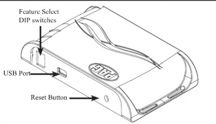
text_image
Feature Select DIP switches USB Port Reset Button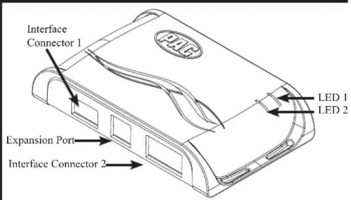
text_image
Interface Connector 1 LED 1 LED 2 Expansion Port Interface Connector 2Installation Steps
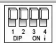
Set DIP switches to the ON position to activate the corresponding features. Set DIP switches to the OFF position for any features that are not desired.
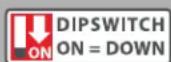
| Reverse Camera Rear Media Navigation Unlock Feature Settings Menu | |||
| 1 2 3 4 | |||
- Set DIP switches to the ON position that correspond with the features you want to add. Feature DIP switches (1-3) must be set before connecting the interface to the vehicle harness.
a. DIP switch 4 - Turning ON DIP switch 4 will allow you to access the Feature Settings Menu through the vehicles Multi Function Display to turn additional features On / Off. These features can also be set using the BCI App. Please see Page 6 for a full list and description of each of the BCI features. - At this point, you can plug the BCI into a Windows PC and set up the programmable outputs, blind spot and / or front camera operation, as well as enable any other features of the BCI using the BCI App. See page 6 for more details on the BCI app.
- Remove the factory radio and disconnect the factory harness(es).
- Connect the factory harness into the female connector on the BCI-CH41 harness.
Installation Steps (cont.)
- Connect the aftermarket reverse camera's video output to the female camera input located on the radio side of the BCI-CH41 harness. If you are also adding blind spot and / or a front camera, the VS41 must be used (sold separately). See below for VS41 wiring. You can also use any universal video switcher and utilize the programmable outputs to trigger as necessary.
- Connect the trigger wire(s) as needed. Please see chart for trigger wire colors and functions.
- If you wish to use the on-demand activation feature, run and mount the toggle switch on the BCI-CH41 harness to the desired location. PLEASE NOTE: If you are not adding a front camera, the on-demand switch will only trigger the reverse camera.
- If you are adding an additional A/V input: Connect the A/V outputs from the source to the Rear Media inputs on the radio side of the BCI-CH41 harness. If you have more than one source, the AVS21 or any other universal video switcher must be used (sold separately).
- Connect the male connector on the BCI-CH41 harness to the factory radio.
- Turn the ignition to the on position.
- Plug the 4-pin and 20-pin plugs on the BCI-CH41 harness into interface connector 1 and 2.
- Both LEDs will blink green while the module is initializing. Once initialized, LED 1 will turn solid red and LED 2 will begin blinking green. If LED 2 blinks red, there is a problem with the data connection to the factory radio. In this case please refer to the troubleshooting section on page 8.
- Turn the vehicle off, shut the doors and lock the vehicle with the factory keyfob. Wait 10 minutes. After 10 minutes, turn vehicle back on and test BCI operation (see operation section on page 4). Sometimes it may take more than one sleep cycle to engage all features, especially the performance page feature.
| Trigger Wires | |||
| Wire | Color | Function | Note |
| Prog. Output 1 | Blue | 12v+ | 10 Amp positive output when user programmed feature is activated |
| Prog. Output 2 | Blue / White | 12v+ | 1 Amp positive output when user programmed feature is activated |
| Prog. Output 3 | Blue / Red | 12v+ | 1 Amp positive output when user programmed feature is activated |
| Left Camera | Red | 12v+ | 1 Amp positive output when left blind spot camera is activated |
| Left Camera | Black | Ground | Negative output when left blind spot camera is activated |
| Right Camera | Red | 12v+ | 1 Amp positive output when right blind spot camera is activated |
| Right Camera | Black | Ground | Negative output when left blind spot camera is activated |
Connecting a VS41 (sold separately)
If you are adding a front camera and two blind spot cameras, or any combination of the three, to the factory radio, a VS41 (sold separately) can be used in conjunction with the BCI. Follow the example below to make all inputs work accordingly through the one camera input on the factory radio. Connect the 10-pin harness from the VS41 harness into the Expansion Port on the BCI-CH41. Do not manually wire the trigger wires, or power and ground leads, when using the Expansion Port connector. When the appropriate CAN-Bus signals are detected (ie. reverse, or turn signal) the corresponding camera input will be automatically selected, and it's video feed will be routed to the factory radio display.
The behaviors of the cameras and output wires can be configured using the BCI app. Please see page 6 for full details on using the BCI app.
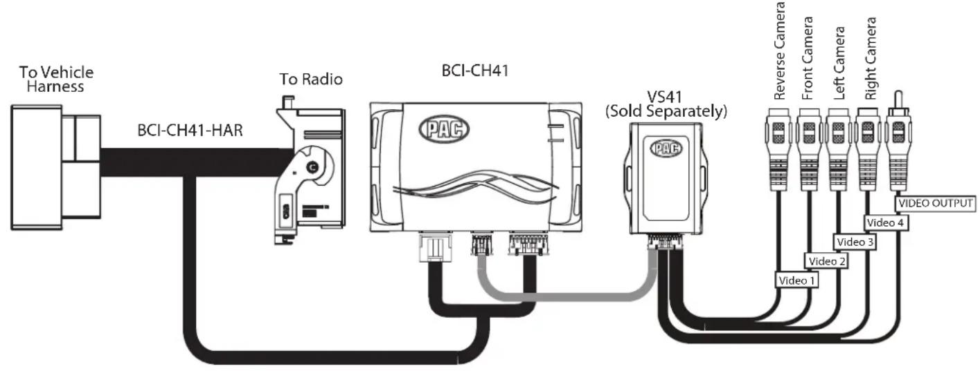
flowchart
graph LR
    A["To Vehicle Harness"] --> B["BCI-CH41-HAR"]
    C["To Radio"] --> B
    B --> D["BCI-CH41"]
    D --> E["VS41 (Sold Separately)"]
    E --> F["Video 1"]
    E --> G["Video 2"]
    E --> H["Video 3"]
    E --> I["Video 4"]
    E --> J["Video OUTPUT"]
    D --> K["Reverse Camera"]
    D --> L["Front Camera"]
    D --> M["Left Camera"]
    D --> N["Right Camera"]
Common Use Examples w/Setup
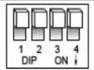
Set DIP switches to the ON position to activate the corresponding features.
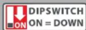
Set DIP switches to the OFF position for any features that are not desired.
| Reverse Camera Rear Media Navigation Unlock Feature Settings Menu | |||
| 1 2 3 | 4 | ||
Adding Reverse Camera Only
• DIP switch 1 = ON
• DIP switch 2 = OFF
• DIP switch 3 = OFF
• DIP switch 4 = User Preference
- No additional programming needed as Programmable Output 1 (10A) is set to "Accessory" by default (use to power cameras)
Adding Reverse Camera and Navigation Unlock
• DIP switch 1 = ON
• DIP switch 2 = OFF
• DIP switch 3 = ON
• DIP switch 4 = User Preference
- No additional programming needed as Programmable Output 1 (10A) is set to "Accessory" by default (use to power camera)
Adding Reverse Camera and Rear Media
• DIP switch 1 = ON
• DIP switch 2 = ON
• DIP switch 3 = User Preference
• DIP switch 4 = User Preference
- No additional programming needed as Programmable Output 1 (10A) is set to accessory by default (use to power cameras and video source)
Adding Reverse Camera and a Bed Camera using the AVS21 (sold separately)
• DIP switch 1 = ON
• DIP switch 2 = OFF
• DIP switch 3 = OFF
• DIP switch 4 = User Preference
- PC Settings
- Blind Spot Camera = OFF.
- Front Camera = OFF
- Programmable Output 1 (10A) = Any Camera Active or Accessory (use to power cameras)
- Programmable Output 2 (1A) = Forced Reverse Camera (use to trigger AVS21 when the forced reverse camera feature is triggered via the SWC or the on-demand switch)
- Programmable Output 3 (1A) = OFF
Adding Blind Spot Cameras using the VS41 (sold separately)
- DIP switch 1 = ON if adding rev cam; OFF if already equipped
• DIP switch 2 = OFF
• DIP switch 3 = User Preference
• DIP switch 4 = User Preference -
PC Settings
-
Blind Spot Camera = User Preference, can't be OFF
- Front Camera = Off
- Programmable Output 1 (10A) = Any Camera Active or Accessory (use to power cameras)
• Programmable Output 2 = OFF
• Programmable Output 3 = OFF
Adding Blind Spot Cameras and a Front Camera using the VS41 (sold separately)
- DIP switch 1 = ON if adding reverse camera; OFF if already equipped
• DIP switch 2 = OFF
• DIP switch 3 = User Preference
• DIP switch 4 = User Preference -
PC Settings
-
Blind Spot Camera = User Preference, can't be OFF.
- Front Camera = User Preference, can't be OFF.
- Programmable Output 1 (10A) = Any Camera Active or Accessory (use to power cameras)
• Programmable Output 2 (1A) = OFF
• Programmable Output 3 (1A) = OFF
Adding Reverse Camera, Blind Spot Cameras, and a Front Camera using the VS41 (sold separately), a bed camera using the AVS21 (sold separately), Navigation Unlock, and Rear Media
• DIP switch 1 = ON
• DIP switch 2 = ON
• DIP switch 3 = ON
• DIP switch 4 = User Preference
- PC Settings
- Blind Spot Camera = User Preference, can't be OFF.
- Front Camera = User Preference, can't be OFF.
- Programmable Output 1 (10A) = Accessory (use to power cameras and video source)
- Programmable Output 2 (1A) = Forced Reverse Camera (use to trigger AVS21 when the forced reverse camera feature is triggered via the SWC or the on-demand switch)
- Programmable Output 3 (1A) = OFF
Operation
Feature Settings Menu
PLEASE NOTE:
• DIP switch 4 must be on in order to access the BCI Feature Settings Menu through the vehicle.
- Please see page 7 for a full list and description of each of the BCI-CH41 features.
• These features can also be set using the BCI App. Please see page 6 for more info on the BCI App.
To Access the Feature Settings Menu
- Place the Multi Function Display into the mode that displays radio text.
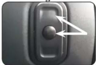
- Press and hold the Lock button on the driver door for approximately 5 seconds (see Fig. A). "BCI-CH41 Menu" followed by the product revision number will be displayed on the MFD in the gauge cluster.
- Use the up / down buttons on either side of the back of the steering wheel to scroll through the features in the menu. Press the center button to scroll through options within the feature (Fig. B).
a. If the vehicle is not equipped with SWC on the back of the steering wheel, you can use the forward and back arrows on the front of the steering wheel to navigate through the menu and use the VR button to change selections and turn features off / on (Fig.C).
- Once all settings have been made, scroll to Exit & Save and press the selection button. The MFD will display "Saving".
- You can now either flip DIP switch 4 OFF to disable access to the menu, or leave it in the ON position to access the menu later.
Fig. A Fig. C
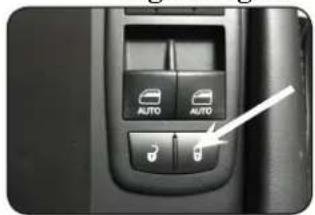
natural_image
Close-up of a car air conditioner control panel with two buttons and a white arrow pointing to the button (no text or symbols visible)Fig. B
natural_image
Close-up of a black mechanical lever handle with a circular knob and two white arrows pointing to the pivot point (no text or symbols visible)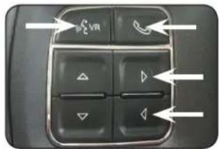
text_image
VRReverse Camera
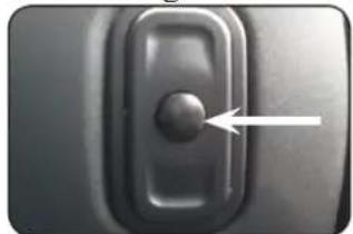
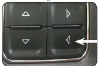
If you have DIP switch 1 in the ON position, the factory screen will switch to the reverse camera whenever the vehicle is placed into reverse. You can also force the reverse camera at anytime by pressing and holding the center button on the back left side of the steering wheel for at least 4 seconds (Fig. D). If your vehicle does not have SWC on the back of the steering wheel, you can use the back button on the front of the steering wheel (Fig. E) or the included on-demand activation switch.
PLEASE NOTE: The OEM reverse camera will turn off when the vehicle exceeds 5 MPH. This is a limitation of the vehicle, not the BCI-CH41.
Fig. D
natural_image
Close-up of a mechanical switch or lever component with a circular knob and an arrow pointing to it (no text or symbols visible)Fig. E
natural_image
Close-up of a black control panel with four directional buttons and a white arrow pointing to the right (no text or symbols visible)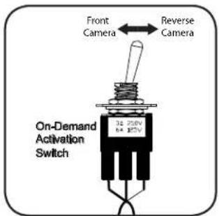
text_image
Front Camera ← Reverse Camera On-Demand Activation Switch 30 Ω 250V N=1.875%Operation (cont.)
Front Camera (VS41 required)
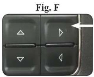
You can set up the front camera to be triggered a variety of different ways. Please refer to the chart on Page 7 for a full list. Whenever one of the feature settings for front camera is on, you can manually force the front camera at anytime by pressing and holding the forward arrow on the front of the steering wheel (Fig. F) or by using the included on-demand activation switch.
text_image
Fig. F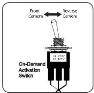
text_image
Front Camera ← Reverse Camera On-Demand Activation SwitchRear Media Mode
If you have DIP switch 2 in the ON position, it will activate Rear Media mode on the factory screen (8.4" screens only).
PLEASE NOTE: In order to access Rear Media mode for the first time, you will need to turn the key ON, then OFF and let the vehicle go to sleep (about 1 minute), then turn the key ON again, then OFF again and let the vehicle go to sleep a second time (about 1 minute).
To access Rear Media mode follow these steps:
- Press the "Media" icon in the bottom left corner of the screen (Fig. G).
- Press the down arrow on the middle left of the screen (Fig. H).
- Press the "AV1" icon on the middle left of the screen (Fig. I).
- Press the "Full" icon on the right middle of the screen to view the video (Fig J). PLEASE NOTE: If you have any of the programmable outputs set to "Rear Media Full Screen", this is the point at which it will become active.
If you have DIP switch 3 turned ON, you can activate the navigation unlock which will enable any features that are normally locked out while the vehicle is in motion.
To activate the navigation unlock, follow these steps:
- Place the MFD in the mode that displays radio text.
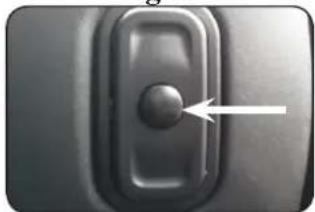
- Press and hold the center button on the back right side of the steering wheel for at least 2 seconds, then release (Fig. K).
- The MFD in the cluster will display "Confirm Safe Passenger Use".
- Press the same button again within 5 seconds to acknowledge "safe use", agreeing that use will be performed only by the passenger whenever the vehicle is in motion, and activate the navigation unlock.
- The MFD will display "Acknowledged".
- To de-activate the navigation unlock simply press and hold the same button for at least 4 seconds and then release.
- The MFD will display "NU Deactivated".
Fig. K
natural_image
Close-up of a black mechanical switch or lever with a circular knob and an arrow pointing to the pivot point (no text or symbols visible)Operation (cont.)
Preset EQ
- This feature is only available in vehicles equipped with a factory amplifier.
- If you are using preset 1, 2 or 3 and not "P", the EQ shown on the radio may not be what you are hearing. The interface cannot force EQ settings that the user has stored onto the factory radio.
This feature can be enabled in the Feature Settings menu outlined on Page 3, or by using the PAC app. Presets can be viewed on the MFD when it is set to audio mode and the Mute button is pressed.
To access / store presets follow the procedure below.
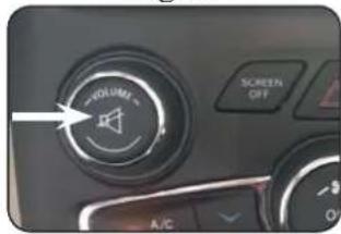
- Presets can be recalled by simply pressing the Mute button located in the center of the volume knob (Fig L). Repeatedly pressing this button will scroll through the presets and the pass through. The pass through is the one labeled "P" and will set the EQ to whatever is displayed on the radio screen.
- To store a preset, press the Mute button until you get to the desired location. Next, go to the equalizer screen by pressing Audio > Equalizer and set it to the desired sound. Now press and hold the Mute button (Fig L) until the MFD displays "Storing EQ".
Fig. L
text_image
VOLUME SCREEN OFF A/CBCI App
PLEASE NOTE:
The BCI must be programmed with revision 12 or higher to support app programmability. You can program the BCI either on the bench or in the car (with ignition on). To program the BCI module with the BCI App, follow these steps:
- Download and install the BCI App. It can be found online at pac-audio.com/app-downloads. Once installed, open the app.
- Connect the interface to the PC.
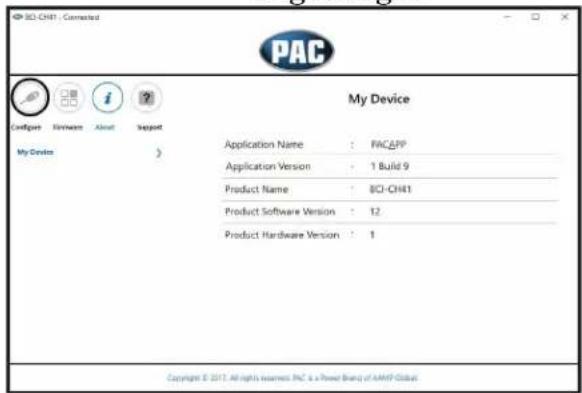
- When first connected, the revision info for both the app and the interface should be displayed. Select "Configure". (Fig A).
- You may now choose between "Camera Settings" and "Interface User Options" on the left, then make selections within those categories on the right (Fig B) Please reference the chart below for all available features and descriptions..
- Once all selections have been made, you can simply disconnect the interface and install it.
PLEASE NOTE: The features outlined in Fig B may or may not be available in your vehicle. Once the interface has been connected to your vehicle, it will determine what is there, and show the correct options in the Vehicle Setting menu available through the MFD.
Fig A Fig B
text_image
PAC My Device Application Name : PACAPP Application Version : 1 Build 9 Product Name : BCI-CH41 Product Software Version : 12 Product Hardware Version : 1 Copyright © 2017. All rights reserved. Inc. is a Power Board of AMIP Global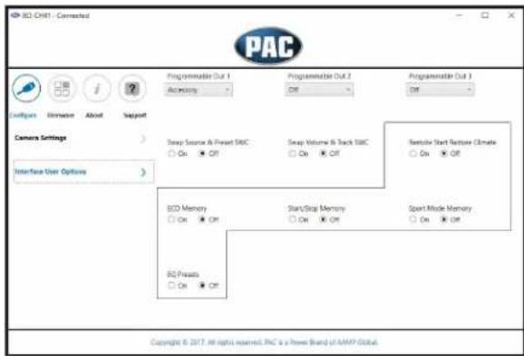
text_image
PAC Camera Settings Interface User Options Programmable Out 1 Accuracy Programmable Out 2 Off Programmable Out 3 Off Swap Source & Print SBC On Off Swap Volume & Track SBC On Off Remote Start Network Climate On Off ECD Memory On Off Start/Stop Memory On Off Sport Mode Memory On Off ECD Presets On Off Copyright © 2017. All rights reserved. PNC is a Power Board of AAMP GlobalBCI Feature Setting Menu
| Available BCI-CH41 Features | |||
| Camera Settings | |||
| Feature | Option | Description | Notes |
| Toggle Switch | Reverse/Font | On-Demand toggle switch will activate the Reverse or Front cameras | If navigation is being used and the camera input is engaged UNDER 20 MPH, it will affect the navigation guidance until the camera input is switched off. |
| Left/Right | On-Demand toggle switch will activate the Left or Right cameras | ||
| Blind Spot Camera | Double tap turn signal | This will activate the camera input when you double tap the turn signal within 2 seconds. | |
| Turn Signal | This will activate the camera input whenever a turn signal is on. | ||
| Turn signal and moving above xMPH | This will activate the camera input when a turn signal is active and the vehicle is going faster than the designated number. | ||
| Front Cam | Greater than 0MPH and less than xMPH | This will activate the camera input whenever the vehicle is going faster than 0 mph or less than the designated number. | |
| Manual Only | This will allow you to activate the camera input manually by using the on-demand activation toggle switch or the forward arrow on the SWC. | ||
| Front Park Assist | This will activate the camera input whenever the front park assist warning system is activated | You must trigger the front park assist before this feature will show up in the menu.This feature is not available in the Chrysler 300 or Dodge Charger. | |
| On when shift into D until 6MPH or 30 seconds | This will activate the camera input whenever the vehicle is placed into Drive. The camera input will turn off once the vehicles MPH is faster than 6MPH, or after 30 seconds. | This mode will not work in vehicles with a manual transmission. | |
| On when shift out of R until 6 MPH or 30 seconds | This will activate the camera input whenever the vehicle is shifted out of reverse. The camera input will turn off once the vehicles MPH is faster than 6MPH, or after 30 seconds. | This mode should only be used in vehicles that have a manual transmission. | |
| Interface User Options | |||
| Feature | Option | Description | Notes |
| Nav Unlock Off/On Turns | the navigation unlock feature off or on. | Once this has been turned on you will still need to activate it by using the back right SWC. | |
| Prog Out 1 | Accessory | This will provide a 12v+ trigger whenever the key is in the accessory or run position. | This is the default setting for Prog Out 1. |
| Any Camera Active | This will provide a 12v+ trigger whenever any camera is triggered. | ||
| Reverse Camera Image | This will provide a 12v+ trigger whenever the vehicle is placed in reverse or the reverse camera is forced on using the SWC or the on-demand activation toggle switch. | ||
| Reverse Gear | This will provide a 12v+ trigger whenever the vehicle is placed in reverse. | ||
| Prog Out 2 & 3 | Accessory | This will provide a 12v+ trigger whenever the key is in the accessory or run position. | |
| Blind Spot | This will provide a 12v+ trigger whenever the blind spot camera is activated. | ||
| Forced Reverse Camera Image | This will provide a 12v+ trigger whenever the reverse camera is forced on using the SWC. | ||
| Front Camera Active | This will provide a 12v+ trigger whenever the front camera is activated. | ||
| Reverse Camera image | This will provide a 12v+ trigger whenever the vehicle is placed in reverse or the reverse camera is forced on using the SWC. | ||
| Reverse Gear | This will provide a 12v+ trigger whenever the vehicle is placed in reverse. | ||
| Off | This is the default setting for Prog Out 2 & 3. | ||
| Swap Source & Preset SWC On/Off | This will allow you to swap the Source and Preset SWC around. | Vehicle must be equipped with audio SWC on the back of the steering wheel. | |
| Swap Track and Volume SWC On/Off | This will allow you to swap the Track and Volume SWC around. | Vehicle must be equipped with audio SWC on the back of the steering wheel. | |
| Remote Start Restore Climate On/Off | This will restore the climate controls to the last known setting on remote start. | Vehicle must be equipped with remote start. | |
| ECO Memory On/Off | This will force the vehicle to remember the ECO mode setting once the vehicles key has been cycled. | Only available in the 2014 Dodge Durango and Jeep Grand Cherokee. | |
| Start/Stop Memory On/Off | This will force the vehicle to remember the Auto Start/Stop mode setting once the vehicles key has been cycled. | Only available in vehicles equipped with Auto Start/Stop system.Must turn Auto Start/Stop feature on/off before it will appear in the BCI menu. | |
| Sport Mode Memory On/Off | This will force the vehicle to remember the Sport mode setting once the vehicles key has been cycled. | Only available in vehicles equipped with Sport Mode.Must turn Sport Mode on/off before it will appear in the BCI menu. | |
| EQ Presets On/Off | This will give you 3 user programmable presets for the factory EQ. | See page 4 of instruction manual for operation. This will only show up if the vehicle is equipped with a factory amplified system. | |
Troubleshooting
- The module can be reset to factory default settings by pressing and holding the Programming button (on the side of the module) for 5 seconds. When pressing and holding the button, both LEDs will blink red while the module is resetting. Once reset, both LEDs will blink green, this indicates the module is initializing, release the programming button.
- The LEDs on the module can tell you what the BCI-CH41 is doing. Please refer to the chart below for LED status patterns and possible troubleshooting actions.
| LED Pattern | State | Action |
| Dual flashing green initializing | Turn on ignitionWait for BCI to finish initializing | |
| LED 1 solid green | Active | N/A |
| LED 2 flashing green | CAN Activity | N/A |
| LED 1 solid red | Programmable output 1 active | N/A |
| LED 2 flashing red No | CAN communication | Check harness and connector pins for proper connection or change status of loop (cut or re-connect) |
| LED 1 flashing red | Resetting | N/A |
| LED 2 flashing amber | USB connected | N/A |