
F35 - Vidéo-projecteur Barco - Free user manual and instructions
Find the device manual for free F35 Barco in PDF.


| Product type | Single-chip DLP video projector |
| Available resolutions | WQXGA (2560x1600), WUXGA (1920x1200), 1080p (1920x1080), Panorama (2560x1080) |
| Light source | Dual 300W UHP lamps or LED illumination (model dependent) |
| Lamp life (UHP) | 2000 hours full power / 2500 hours eco mode; up to 5000 hours in auto-switch eco mode |
| Lamp life (LED) | Up to 100,000 hours (full power and eco mode) |
| Dimensions (D x W x H) | 376 x 510 x 223 mm (excluding lens) |
| Weight | Approximately 12.6 kg (excluding lens) |
| Power requirements | 100-240 V, 50-60 Hz, 8.4 A max |
| Power consumption | < 1050 W (UHP) / < 325 W (LED) |
| Optics | Powered lens shift (horizontal & vertical), motorized zoom and focus, bayonet lens mount |
| Color processing | RealColor advanced color management, BrilliantColor 6-color processing, selectable gamma curves |
| Inputs | 2x DVI-D (dual link up to 330 MHz), 2x HDMI 1.3a, 2x VGA, YPbPr, 2x X-PORT slots |
| Control interfaces | LAN (10/100), RS-232, USB (for software upgrade), IR remote (laser class II) |
| 3D support | Active stereo 3D on 1080p and WUXGA models; side-by-side, frame sequential, top/bottom via X-PORT modules |
| Installation flexibility | Desktop front/rear, ceiling front/rear; ceiling mount (UL listed, capacity min 60 kg) |
| Safety features | Automatic power off on overheat, pin code protection, remote control ID, DPMS, timer |
| Operating temperature | 0-40°C (32-104°F) at 0-1500 m; 0-35°C (32-95°F) at 1500-3000 m |
| Compliance | CE, FCC Class A, cCSAus, RoHS, WEEE |
| Maintenance | Lamp hot-swap (UHP), software upgrade via USB, preventive maintenance recommended after 8000 hours |
| Warranty | Use only original lamps; authorized dealer for service; no user-serviceable parts |
Frequently Asked Questions - F35 Barco
User questions about F35 Barco
0 question about this device. Answer the ones you know or ask your own.
Ask a new question about this device
Download the instructions for your Vidéo-projecteur in PDF format for free! Find your manual F35 - Barco and take your electronic device back in hand. On this page are published all the documents necessary for the use of your device. F35 by Barco.
USER MANUAL F35 Barco
natural_image
Close-up of a white BARCO camera lens with pink lens, showing aperture and lens dimensions (no text or symbols on the lens itself)1 Contents of this User's Guide
1 Introduction 6
1.1 Thank you
1.2 Features
2. Safety Instructions 9
2.1 SAFETY
2.2 GENERAL WARNINGS
2.2.2 HEAVY DUTY AND CONTINUOUS USE (UHP lamps only)
2.2.3 SERVICE PERSONNEL INFORMATION WARNING (UHP lamps only)
2.2.4 REMOTE CONTROL WARNING
2.2.5 WARNING SYMBOLS
2.3 FCC
2.4 WEEE INFORMATION
2.4.1 Turkey RoHS compliance
2.5 ENVIRONMENTAL INFORMATION
2.5.1 Disposal Information
2.5.2 Disposal of batteries in the product
2.6 SERVICE INFORMATION
2.2.1 INFORMATION AND WARNING ABOUT POTENTIAL HEALTH ISSUES RELATED TO MERCURY VAPOR (UHP lamps only)
3 What's in the box? 13
4. Getting to know the projector 15
4.1 Overview
4.2 Indicators
4.2.1 The status indicator
4.2.2 Keypad
4.2.3 Remote control
4.3 Connectivity
4.4 Graphical User Interface (GUI)
5. Basic setup 21
5.1 Lens
5.1.1 Lens and lens mount
5.1.2 Inserting a lens
5.1.3 Replacing a lens
5.2 Adjusting on screen image size and position
5.3 Lamp operation
5.4 Projector rotation
5.5 Ceiling mount
5.5.1 Ceiling mount cover (optional)
5.5.2 Attaching the ceiling cover
5.6 Connection and cables
5.6.1 Setting up a video source
5.6.2 Setting up a computer source
5.6.3 Connecting command and control interfaces
5.6.4 Attaching X-PORT™ modules
5.7 Using X-PORT™ modules
5.7.1 X-PORT DCC120
5.7.2 X-PORT 3G-SDI
5.7.3 X-PORT HDMI 3D
5.8 Image alignment
5.9 Setting image orientation
5.10 Using source scan
5.11 Limiting OSD messages
5.12 Changing the language of the menu system
5.13 Identifying system status
5.13.1 Getting information about the active source
5.14 Using the dual lamp system (UHP models only)
5.15 Configuring 3D (AS3D)
5.16 Image sizes
6 Advanced setup 35
6.1 Controlling multiple projectors with remote control ID (RCID)
6.2 Protecting the projector with a pin code
6.3 Using dual head input
6.4 Multi-channel 3D synchronization
6.4.1 Synchronous frame sequential
6.4.2 Asynchronous frame sequential
6.4.3 Synchronous side-by-side
6.4.4 Asynchronous side-by-side
6.5 Setting custom color space and digital level
6.6 Disabling IR receivers
6.7 Controlling screens with triggers
6.8 Setting aspect trigger behavior
6.9 Automatic power on/off
6.9.1 Using the timer
6.9.2 Using DPMS (Display Power Management Signaling)
6.10 Disabling LED indicators
6.11 Setting the background color
6.12 Selecting the startup logo
6.13 Setting OSD menu timeout
6.14 Selecting the startup logo
7 Optimising the picture 43
7.1 Calibration data
7.1.1 Updating RealColor™ calibration data
7.2 Working with RealColor™
7.2.1 Setting the BrilliantColor™ correctly
7.2.2 Gamma
7.2.3 RealColor™ operating modes
7.2.4 Setting a white point or color temperature
7.2.5 Defining the system color gamut
8 Maintenance 49
8.1 Software upgrades
8.2 Lamp replacement (UHP units only)
9 Technical specifications 51
9.1 Product details
1 Introduction
1.1 Thank you
Thank you for purchasing this projector.
When referring to the term F35/FL35 in this document, it means that the content is applicable for following Barco products:
• F35 1080p FL35 1080p
• F35 WUXGA FL35 WUXGA FS35 IR WUXGA + Addendum
• F35 WQXGA FL35 WQXGA FS35 IR WQXGA + Addendum
• F35 Panorama (2560x1080)
The F85 series projectors set an industry benchmark for projectors in its size and performance category. Featuring high resolution DLP technology, high performance optics and lenses, updated signal processing and built-in frame-lock synchronisation makes it the ideal projector for multi-channel visualisation and simulation applications, where realism and reliability are key criteria. In addition the excellent image performance, the 1080p and WUXGA version are capable of Active Stereo 3D.
1.2 Features
- 1080p (1920x1080), WUXGA (1920 x 1200), panorama (2560x1080) or WQXGA (2560 x 1600) resolution single chip DLP® technology
- Patented Dual Architecture or LED illumination system and optics
• RealColor advanced colour management suite - Fail safe, hot swap Dual Lamp architecture or longlife LED illumination
- Dual optomechanical IRIS for customizable brightness and contrast
• Full powered horizontal and vertical lens shift, allows direct stacking
• Full 12-bit colour resolution for minimised artefacting and high accuracy - BrilliantColor™ technology with six-colour processing for accurate colours
• Elevated contrast levels for unmatched image dynamics
• High brightness for large screen applications - Range of application specific colour wheel options
- Wide range of projection lenses
• Highly versatile colour management and calibration options
• Built-in real time clock for timed operations - Sigma Designs™ technology video de-interlacing and processing
• Economy mode for reduced power consumption and prolonged lamp life - Small and ergonomic footprint, with low weight
- Direct view status monitor and lamp function indicators
- Multiple video and graphics inputs for virtually any video and data source
• Dual Link DVI (330 MHz) - HDMI ver. 1.3a
• LAN and RS232 for control and monitoring
Symbols used in this documentation

WARNING: Used to point out potential danger to people or equipment when using this product or peripheral equipment.

NOTE: Used to point out essential handling requirements for the projector, which if not acted on may cause product malfunctioning.

TIP: Used to give advice which benefits the projector usage or conditions related to projector performance.
The specifications and functionality of this projector may change without prior notice.
The cabinet colour of your product may differ from the one shown in the pictures in this manual.
2 What's in the box?
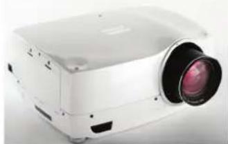
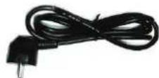
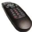
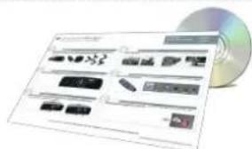
The following components are standard delivery:
Projector
natural_image
White projector with a black lens and red lens, shown against a plain background (no text or symbols visible)Power Cable (Country Dependent)
Remote Control
User Documentation
natural_image
CD or DVD interface showing various electronic components and icons (no readable text or symbols)Additional accessories available for the projector:
DVI-cable
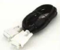
Please verify that you have all components upon unpacking the unit, and its contents. Check next page for additional accessories.

Please save packaging materials for future use, should it be necessary to ship the unit.
2 Safety Instructions
This device complies with safety regulations for Information Technology Equipment for use in an office environment. Before using the device for the first time, please read the safety instructions thoroughly.
2.1 SAFETY
This user guide contains important information about safety precautions and the set-up and use of the projector. Please read the manual carefully before you operate the projector.
2.2 GENERAL WARNINGS
Use only the cables and cords supplied with the projector or original replacement cables. Using other cables or cords may lead to malfunction and permanent damage of the unit.
Always use 3-prong / grounded power cord to ensure proper grounding of the unit. Never use 2-prong power cords, as this is dangerous and could lead to electrical shock.
Never open the unit. The projector contains no user serviceable parts. Refer all repairs to qualified personnel only. Make sure that no objects enter into the vents and openings of the set.
Do not spill any liquids on the projector or into the vents or openings of the unit.
Always remove lens cap before switching on the projector. If the lens cap is not removed, it may melt due to the high energy light emitted through the lens. Melting the lens cap may permanently damage the surface of the projection lens.
Do not look into the projection lens when the projector is switched on. The strong light may permanently damage sight. Do not look into the laser beam when activated on the remote control. Laser light may permanently damage sight.
Do not point laser beam at people or animals.
Only place the projector on a stable surface, or mount it securely using an approved ceiling-mount.
Do not drop the projector.

Always operate the projector according to the rotation guidelines. Operating the unit in other positions may reduce lamp life significantly, and may lead to overheating, resulting in malfunctioning.
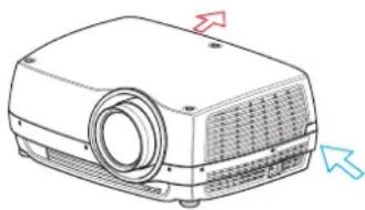
Always allow ample airflow through the projector. Never block any of the air vents. Never cover the unit in any way while running. Allow for sufficient distance to walls and ceilings to avoid overheating.
Minimum safety distance to any side of the unit is 50 cm / 20" in any direction.
Hot air is exhausted from the rear vent. Do not place objects that are sensitive to heat nearer than 50cm / 20" to the exhaust vent.
The projector is designed for indoor use only. Never operate the unit outdoors.
Do not operate the projector outside its temperature and humidity specifications, as this may result in overheating and malfunctioning.

Connecting sources to a powered projector may result in product failure. It is recommended that the power cable connector (projector-end) or the mains power socket are accessible while the product is in use to enable mains power to be disconnected or switched off when connecting source devices. This should be considered during product installation.
natural_image
Illustration of a projector with ventilation grilles and a circular lens (no text or symbols)Only connect the projector to signal sources and voltages as described in the technical specification. Connecting to unspecified signal sources or voltages may lead to malfunction and permanent damage of the unit.
In order to prevent damage to the projector caused by overvoltages (e.g. lightning), we recommend connection to a line (mains) circuit which has overvoltage protection.
Allow lamp to cool down before changing. One lamp may be changed while the other lamp is operating (hot-swap). USE ONLY ORIGINAL LAMPS.
2.2.1 INFORMATION AND WARNING ABOUT POTENTIAL HEALTH ISSUES RELATED TO MERCURY VAPOR (UHP lamps only)
This projector uses a very powerful UHP ^™ lamp for illumination to produce an extremely bright image.
This technology is similar to other high-pressure discharge lamps that are extensively used in cars, street lights and other lighting appliances today. These lamps, like fluorescent lighting, contain small amounts of mercury. The amount of mercury present in a lamp is far below the limits of danger. It is very important that lamps containing mercury are treated properly to minimize potential health hazards.
The UHP ^™ lamp, like any other high brightness projector lamp, is under high-pressure when operating. While the lamp and the projector are carefully designed to minimize the probability of lamp rupture, the lamp may break while operating and small amounts of mercury vapor may be emitted from the projector. The probability of rupture increases when the lamp reaches its expected lifetime. It is therefore highly recommended that the lamp is replaced when the rated lifetime is reached.
As a general precaution, secure good ventilation in the room when operating the projector. If lamp rupture occurs, evacuate the room and secure good ventilation. Children and pregnant women in particular should leave the room.
When replacing a worn lamp, dispose of the used lamp carefully by proper recycling.
Mercury is a naturally occurring, stable metallic element that may pose a safety risk to people under certain conditions. According to the Public Health Statement for Mercury published by the Agency for Toxic Substances and Disease Registry (“ATSDR”, part of the United States Public Health Service), the brain, central nervous system and kidneys are sensitive to the effects of mercury, and permanent damage can occur at sufficiently high levels of exposure. Acute exposure to high concentrations of mercury vapor can cause conditions such as lung and airway irritation, tightness in the chest, a burning sensation in the lungs, coughing, nausea, vomiting and diarrhea. Children and fetuses are particularly sensitive to the harmful effects of metallic mercury to the nervous system.
Seek medical attention if any of the above symptoms are experienced or if other unusual conditions are experienced following lamp rupture.
2.2.2 HEAVY DUTY AND CONTINUOUS USE (UHP lamps only)
The projector contains moving parts (such as cooling fans) that have limited life-expectancies. When the projector has been used for 8 000 hours, and when the unit is used in mission-critical applications, it is recommended that the projector is given preventive maintenance by a qualified service person. A message will appear on the screen when the projector is due for preventive maintenance. This will help ensure long term stable operation.
2.2.3 SERVICE PERSONNEL INFORMATION WARNING (UHP lamps only)
Use UV radiation eyes and skin protection during servicing.
2.2.4 REMOTE CONTROL WARNING
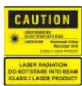
Laser radiation class II product; wavelength 670nm; maximum output 1mW.
Remote control complies with applicable requirements of 21 CFR 1040.10 and 1040.11.
Remote control complies with applicable requirements of EN/IEC 60825-1/2007

Use of controls or adjustments, or performance of procedures other than those specified in the User Guide, may result in hazardous radiation exposure.
2.2.5 WARNING SYMBOLS
Here is a list of warning symbols found on the product lable(s):
READ USER GUIDE Attention! Read the user guide for further information!
⚠️ DANGEROUS VOLTAGE Danger! High voltage inside the product!
HOT Warning! Hot surfaces!
⚠️ WAIT Warning! Wait until cooled down!
Hg MERCURY Warning! Lamp contains mercury! Recycle properly, do not dispose of in ordinary waste!
⚠️ UV Warning! UV radiation inside the product!
RECYCLE Warning! Recycle properly, do not dispose of in ordinary waste!
2.3 FCC
FCC regulations provide that changes or modifications not expressly approved by the party responsible manufacturer could void your authority to operate the equipment.

This equipment has been tested and found to comply with the limits for a Class A digital device, pursuant to part 15 of the FCC Rules. These limits are designed to provide reasonable protection against harmful interference when the equipment is operated in a commercial environment. This equipment generates, uses, and can radiate radio frequency energy and, if not installed and used in accordance with the instruction manual, may cause harmful interference to radio communications. Operation of this equipment in a residential area is likely to cause harmful interference in which case the user will be required to correct the interference at his own expense.
This device complies with part 15 of the FCC Rules. Operation is subject to the following two conditions:
(1) This device may not cause harmful interference, and
(2) this device must accept any interference received, including interference that may cause undesired operation.
CANADA
This is a Class A product. In a domestic environment this product may cause radio interference, in which case the user may be required to take adequate measures.
2.4 WEEE INFORMATION
This product conforms to all requirements of the EU Directive on waste electrical and electronic equipment (WEEE). This product shall be recycled properly. It can be disassembled to facilitate proper recycling of it's individual parts. This product is using projection lamps that shall be recycled properly. Consult your dealer or relevant public authority regarding drop-off points for collection of WEEE.
2.4.1 Turkey RoHS compliance
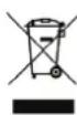
Waste Electrical and Electronic Equipment

This symbol on the product indicates that, under the European Directive 2002/96/EC governing waste from electrical and electronic equipment, this product must not be disposed of with other municipal waste. Please dispose of your waste equipment by handing it over to a designated collection point for the recycling of waste electrical and electronic equipment. To prevent possible harm to the environment or human health from uncontrolled waste disposal, please separate these items from other types of waste and recycle them responsibly to promote the sustainable reuse of material resources.
For more information about recycling of this product, please contact your local city office or your municipal waste disposal service.
For details, please visit the Barco website at: http://www.barco.com/en/AboutBarco/weee
2.5.2 Disposal of batteries in the product

This product contains batteries covered by the Directive 2006/66/EC which must be collected and disposed of separately from municipal waste.
If the battery contains more than the specified values of lead (Pb), mercury (Hg) or cadmium (Cd), these chemical symbols will appear below the crossed-out wheeled bin symbol.
By participating in separate collection of batteries, you will help to ensure proper disposal and to prevent potential negative effects on the environment and human health.
2.6 SERVICE INFORMATION
This product contains no user serviceable parts. If the product fails to function as expected, please first check that all connections are properly made, and that the power cord is properly connected. Please check that the projector as well as the video and computer sources are all switched on. Cables and cords may break over time. Try to change cables and cords, in case there is a bad or intermittent connection. Check if the circuit breaker or fuse of your mains is intact. In the event of product failure, please contact your reseller. You should prepare a description of the symptoms of failure you experience. Please also state product number and serial number as printed on the label on the bottom of the projector.
3 Getting to know the projector
3.1 Overview
A Lens
B IR sensor
C1 Ventilation - Air flow IN
C2 Ventilation - Air flow OUT
D Lens release
E Power connector
F Keypad
G Connector panel
H LCD
I Lamp lids*
J Adjustable feet
K Security lock
L Ceiling mount
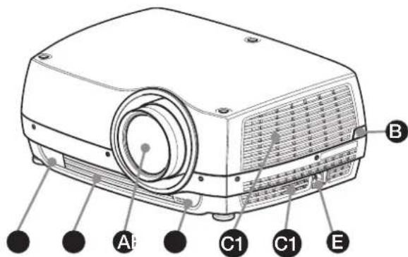
Figure 3-1. - Projector front view
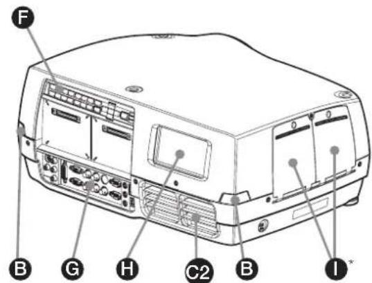
Figure 3-2. - Projector rear view
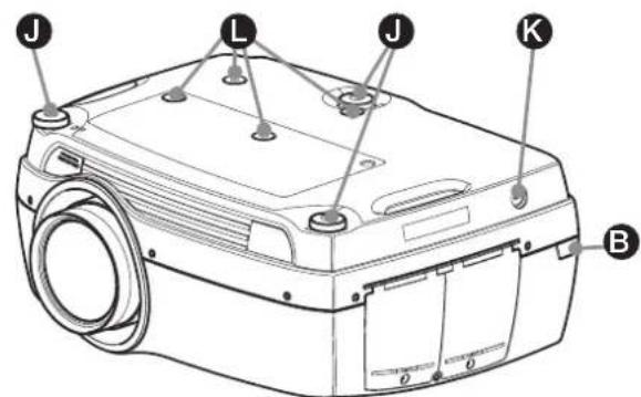
Figure 3-3. - Projector bottom view
* Features in the user guide pictures/drawings may be different from your projector depending on model/version.
3.2 Indicators
System status indicators are located right of the keypad on the back of the projector. Figure 4-4 shows the three status indicators – one for each lamp and one for the system status.
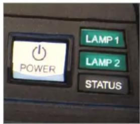
Figure 3-4. The lamp indicators
* Pictures show backpanel of projector with UHP lamps.
LED illumination projectors have one indicator lamp (LED), instead of two (LAMP 1, LAMP 2).
For the lamp indicators the following apply:
- PERMANENT GREEN LIGHT: The lamp is on and operating normally.
- PERMANENT YELLOW LIGHT: The lamp is off. The lamp may be disabled in the menu or the system is in standby.
- PERMANENT RED LIGHT: Lamp life has expired, lamp is not igniting or lamp door is open. If the lamp life has expired, please change projection lamp immediately. Failing to change lamp may lead to lamp explosion. Please replace with original projectiondesign replacement lamp.
- FLASHING YELLOW LIGHT: The lamp is cooling down. The total cooling down time is approx. 45 seconds.
- NO LIGHT: No lamp inserted.
The replacement lamps must be purchased from an authorized projectiondesign dealer for the warranty of the product to be valid. Using lamps from any other after market supplier will void the warranty.
3.2.1 The status indicator
- PERMANENT GREEN LIGHT: The projector is turned on and in normal operation.
- PERMANENT YELLOW LIGHT: The projector is in standby mode. If the projector was powered off by the power saving feature (DPMS), it will automatically power on when you connect a valid source.
- FLASHING YELLOW LIGHT: Please wait. The yellow light will flash a period after power cord is connected (20-30 sec.), and a period after going to standby mode while lamp is cooling down (approximately 45 sec.). The projector may not be turned on again until the light has turned to permanent yellow.
- FLASHING RED LIGHT: Projector is overheated. Turn off immediately! Check if air inlets are covered or if ambient temperature is outside specifications. The projector cannot be restarted until the power cord is disconnected and reconnected again. If the projector continues to flash red, you will need to return the unit for service.
3.2.2 Keypad
The projector has an illuminated keypad on the back of the unit. Figure 4-5 shows the keypad.

Figure 3-5. Projector keypad
* Pictures show backpanel of projector with UHP lamps.
LED illumination projectors have one indicator lamp (LED), instead of two (LAMP 1, LAMP 2).
The keypad is used to:
- navigate the menu system
- scroll the information in the LCD panel
- directly select input sources
- enter pin code (if enabled)
- power on/off
- adjust basic image functions
The keypad is illuminated for operation in dark environments. Available functions are illuminated in yellow while selected (active) functions are illuminated in green. Functions that are not available are not illuminated.
3.2.3 Remote control
The remote control allows flexible access to the projector settings, either through direct keys, or through the menu system. The remote control is backlit for use in dark environments. It also has a data-jack that allows for wired connection to the projector. When the wire is connected, the IR (infra-red) beam and internal batteries are switched off.

The direct sources buttons for VGA1, VGA2, X-Port 2 and YPbPr are not available for all versions of the product. If your product does not have these inputs implemented the OSD will display "not available" when pressing these buttons.
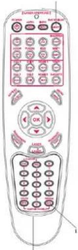

Do not look into the laser beam when activated on the remote control. Laser light may permanently damage eyesight. Avoid pointing the laser beam at people or animals.

Only use the supplied remote control, otherwise the result may be malfunction.
Figure 3-6. Remote control
3.3 Connectivity
he projector features a wide range of video inputs and command/control connectors.
Figure 4-7 shows the connector panel.
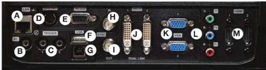
Figure 3-7. Connector panel
A LAN: 10/100 Mbit Ethernet connector for command, control and software upgrade.
B RC INPUT: 3.5mm mini-jack connector. Allows connection of external IR receiver or wired remote control.
C TRIGGERS: 3.5mm mini-jack connector triggers. Used for controlling peripheral equipment like motorized screens.
D 3D SYNC: For 1080/WUXGA 3D projectors used to attach external ir-glass emitters
E RS-232: Allows for wired remote control and monitoring of many projector functions used in installation environments.
F USB-A: Allows for software upgrades using a standard USB memory stick.
G USB-B: Reserved for future use.
H SYNC-IN: Allows for taking an external vertical sync signal and using that with the select video input. This is mainly used in multiple projector installations with requirement of video synchronization between the units.
SYNC-OUT: Constantly outputs the vertical sync signal of the active video input. This is mainly used in multiple projector installations with requirement of synchronization between the units.
J DVI-D: Two Dual Link DVI-D connectors with bandwidth up to 330 Mhz total. These connectors can also be used to form one uniform image by feeding half of the image into each connector. HDCP compliant for sources up 165 Mhz.
K VGA: Two VGA connectors with bandwidth up to 170 Mhz
L YPbPr: Analog video input supporting YPbPr and RGB (sync-on-green) video standard up to 1080i.
M HDMI 1.3: Two HDMI 1.3a connectors with bandwidth up to 165 Mhz each. These connectors can also be used to form one uniform image by feeding half of the image into each connector. HDCP compliant. All video formats specified by the HDMI 1.3a are supported.
3.4 Graphical User Interface (GUI)
The projector has an easy-to-use on screen display (OSD) system for controlling the extensive number of features implemented. Figure 4-8. Top level OSD menu, shows the top level of the OSD menu.
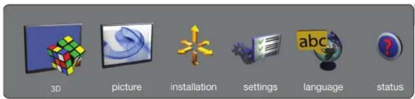
Figure 3-8. Top level OSD menu
Activate the menu by pressing the "MENU" button on either the keypad or the remote control. Navigate the menu using the arrow keys.
The various functions in OSD menu is described in Chapter "5 Basic setup".

The top level menu item 3D is only visible for Active Stereo 3D enabled projectors (1080p and WUXGA).
4 Basic setup
4.1 Lens
4.1.1 Lens and lens mount
A range of fixed and zoom lenses is available to cover most applications, both both for front and rear projection. The lenses are powered and fitted with a bayonet mount for ease of installation.

Switch off all equipment before setting-up for proper function.
When mounting and changing lenses, be aware that the optical system is exposed to dust and foreign particles as long as the lens is not attached to the system. Do not leave the lens mount open longer than necessary to change lens. If a lens is not mounted, always insert the protection lid to avoid dust and foreign particles entering the internal optics.

Never run the projector without lens mounted.
4.1.2 Inserting a lens
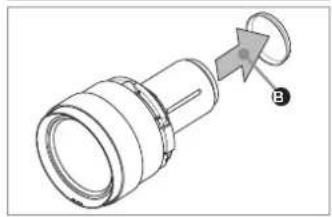
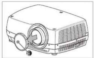
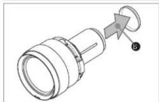
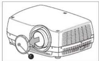
To insert a lens please follow this procedure:
A Remove the protection lid from the bayonet mount by turning the knob anti-clockwise.
B Remove the rear lens cap.
C Attach the projection lens using the bayonet mount, observing the red insertion marks.
D Turn the lens firmly clockwise until it stops with a click.
E Remove the lens cap from the projection lens. If you switch the projector on with the lens cap in place, the lens cap may melt, damaging not only the lens cap, but also the projection lens and surrounding parts.
4.1.3 Replacing a lens
To replace a lens please follow this procedure:
A To change lens, first remove the current lens by pushing the release button and twisting the lens counter-clockwise until it comes loose. Pull the lens out.
B Insert the new lens as described in above.
natural_image
Technical line drawing of a mechanical component with a circular arrow and label B (no text or symbols present)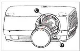
natural_image
Line drawing of a projector with a circular dial and label B (no text or symbols on the device itself)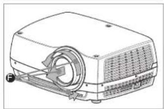
natural_image
Line drawing of a portable projector with ventilation slots and a scroll wheel (no text or symbols)4.2 Adjusting on screen image size and position
Adjusting the placement of the image on screen can be done using the:
- Adjustable feet (E in Figure 5-1).
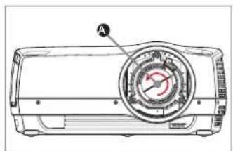
- Lens shift mechanism controlled from the keypad, the remote control, RS-232 or LAN (A in Figure 9).
- Zoom (for lenses with zoom) in the lens controlled from the keypad, the remote control, RS-232 or LAN (B in Figure 5-1).
After the correct image size and position is found, please adjust the image focus using the keypad, the remote control, RS-232 or LAN. (C in Figure 5-1).
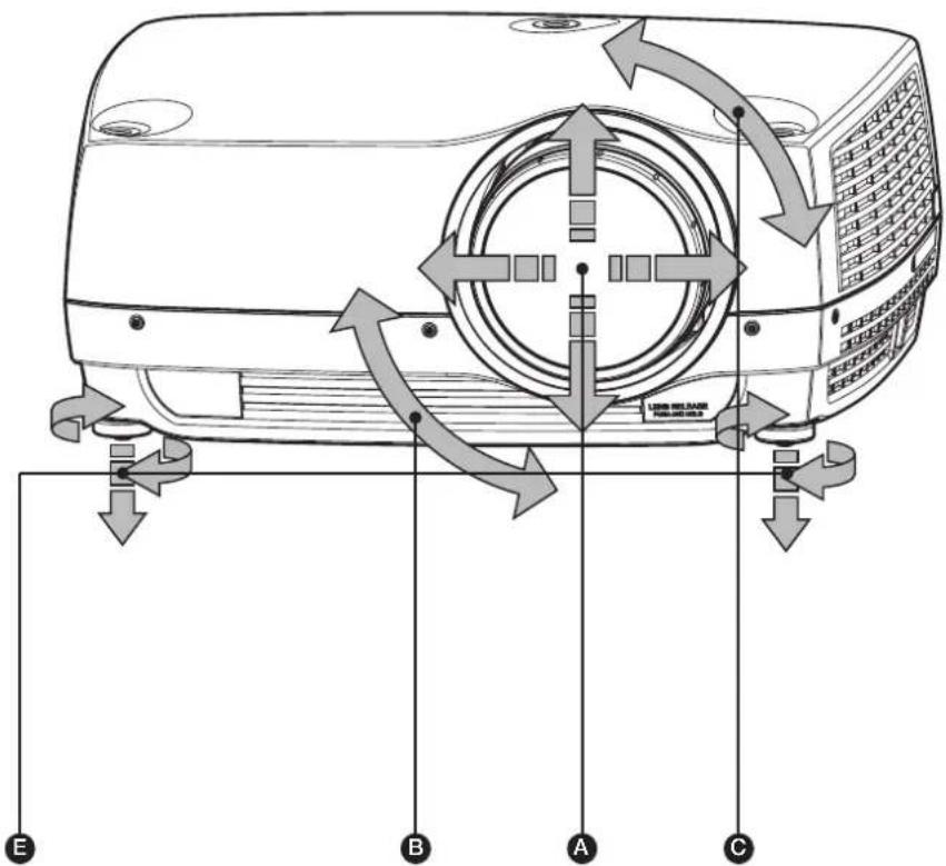
Figure 4-1. Image size ans position adjustment
4.3 Lamp operation
The projector is fitted with two individual projection lamps ^+ that can be run in various modes. In addition, lamps can be replaced as needed separately. This ensures an optimized cost of ownership. Individual lamp timers are maintained for each lamp.
Lamp operation mode is controlled in the INSTALLATION > LAMPS sub menu.
* UHP lamp projectors only. LED projectors have only one lamp.
4.4 Projector rotation
Always operate the projector horizontally, within the range of the adjustable front and rear feet. The projector may be rotated so that the lens points downwards. It may not be rotated around the through-the-lens axis.

Operating the unit in other positions may reduce lamp life significantly, and may lead to overheating, finally resulting in malfunctioning.
4.5 Ceiling mount
The projector can be ceiling mounted using an approved UL tested/ listed ceiling mount fixture, with a capacity of minimum 60 kg / 130 lbs. For ceiling mount use M6 screws that penetrate maximum 15 mm / 0.6" into the projector body. Figure 5-2. Ceiling mount, gives detailed information about the alignment of the ceiling mount screw holes in the projector.

For proper ventilation the minimum distance from ceiling/ rear wall should be: 30/ 50 cm, 12/ 20 inch.
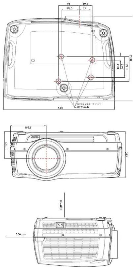
Figure 4-2. Ceiling mount
4.5.1 Ceiling mount cover (optional)
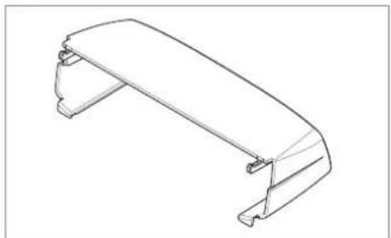
The optional auxiliary cable cover can be mounted on the projector to conceal the interface cables and power cord when the unit is ceiling mounted. Connect all cables and fix them in place before the cable cover is attached to the projector. Figure 5-3 shows the ceiling mount cover.
natural_image
Technical line drawing of a mechanical bracket component (no text or symbols)Figure 4-3. The ceiling mount cover
4.5.2 Attaching the ceiling cover
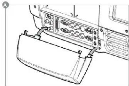
To attach the ceiling mount cover, please follow this procedure:
A Attach the cable cover to the projector by inserting the horizontal hooks on the cover in the horizontal slots on the rear of the projector.
B Turn the cover until the vertical hooks on the cover are inserted into the vertical slots on the rear of the projector.
C The cover will snap in place, to release pull the vertical hooks on the cover out of the slots, letting the cover hinge on the horizontal hooks.
natural_image
Technical line drawing of a device rear panel with connectors and ports (no text or symbols)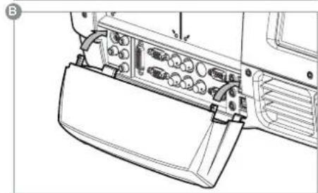
natural_image
Technical line drawing of a vehicle's rear panel with buttons and sensors (no text or symbols)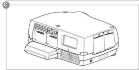
natural_image
Line drawing of a vehicle chassis with front panel and side door (no text or symbols)4.6 Connection and cables

Before setting up, switch off all equipment and disconnect the power cord. In order to prevent damage to the projector caused by overvoltages (e.g. lightning), connect to a line (mains) circuit which has overvoltage protection when installing.
4.6.1 Setting up a video source
For best quality video, connect a digital video source using the HDMI 1.3a interface (O) Connecting a video source in Figure 5-4. The HDMI input is HDCP copy protection compliant. Depending on cable quality, the projector is supporting the use of cables with lengths up 20 meters (65 feet).
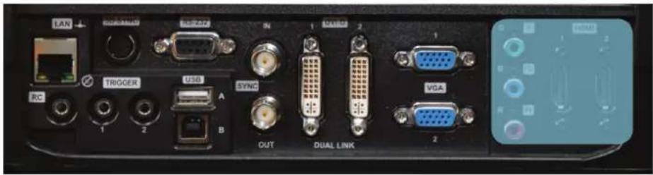
Figure 4-4. Connecting a video source
4.6.2 Setting up a computer source
The projector may be connected to up to six computer sources simultaneously, using the HDMI (O), DVI-D (J) or VGA (K) interfaces, shown in Figure 5-4/Figure 5-5. The digital interfaces (DVI/HDMI) will yield a projected image with very low noise.
Both DVI and HDMI are HDCP compliant with sources up to 1920x1200@60Hz (single link source up to 165 Mhz). Additional functionality may be achieved using additional X-PORT connectors like 3G-SDI, DisplayPort 1.1a and HDMI 3D (se separate sections).
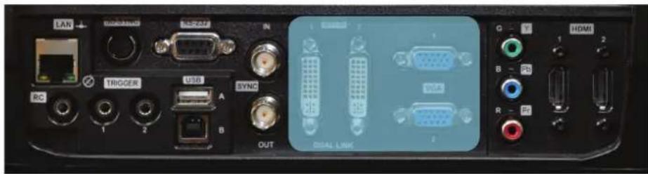
Figure 4-5. Connecting a computer source

HDCP is not supported on higher resolution sources like 2560x1600@60Hz (WQXGA).
Connect the power cord after the other cables have been inserted properly.
4.6.3 Connecting command and control interfaces
The projector is supporting RS-232 and LAN command and control interfaces. Use the ASCII based protocol to communicate with the projector. A detailed description of the ASCII protocol is available for download at www.projectiondesign.com. Connect the power cord after the command and control cables are inserted properly.
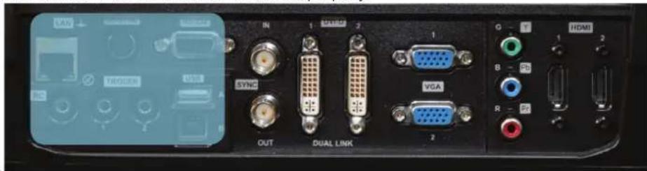
Figure 4-6. Connecting command interfaces
4.6.4 Attaching X-PORT™ modules
! X-PORT™ modules are separately available for purchase and not included with the base projector.
! Switch off projector and disconnect power cord before attaching X-PORT™ module. Before attaching any X-PORT module, please make sure you have the latest SW running on the projector. Please go to www.projectiondesign.com to download the current SW and update the projector accordingly. See chapter 8 for details on how to upgrade the projector SW.
The projector supports up to two X-PORT™ modules simultaneously:
- X-PORT™ 1 for additional image processing (X-PORT™ DCC120*). Left hand side.
- X-PORT™ 2 for additional connectivity (X-PORT™ 3G-SDI, X-PORT™ DisplayPort 1.1a and X-PORT™ HDMI 3D*). Right hand side.
*X-PORT™ modules subject to availability.
To attach an X-PORT™ module, please follow this procedure:
A Remove cover plate, by removing the four screws.
B Attach module. Observe X-PORT™ 1 and 2 positions are different. Attaching X-PORT™ modules in the wrong position will leave the module non-functional, but it is not destructive.
C Fix the four mounting screws securely.
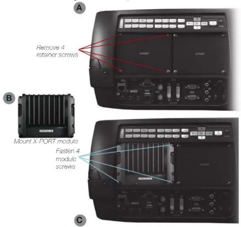
* Features in the user guide pictures/drawings may be different from your projector depending on model/version.
Finally connect power cord and switch on projector.
The first time after a module is attached, the projector will automatically update and configure the module. This may take a few minutes. Please ensure that power remains on during this period.
4.7 Using X-PORT™ modules
X-PORT ^™ modules allows for extra functionality with the projector. This includes more connectivity as well as additional image processing.
Functionality may include extended connectivity (like 3G-SDI and HDMI 3D) and additional 3D format support (like Blu-Ray frame packed, dual input sources, double flash 3D etc.)

Please refer to Chapter 6.4 for information on multi channel 3D sync.
4.7.1 X-PORT DCC120
X-PORT DCC120 is an X-PORT 1 module (post processing) adding additional 3D capabilities and multi-projector synchronization capabilities to the system.
4.7.1.1 3D formats supported
By using X-PORT DCC120 the following 3D format will then be supported:
Dual head input: When “Dual head” is enabled, the projector will combine the signals from DVI1 and DVI2 (or HDMI1 and HDMI2), place them beside each other and interpret it as a single source. The two sources need to have the same resolution. For example, if both inputs are 1920x1200 @ 60Hz, the combined dual head source will be seen by the projector as a single 3840x1200 @ 60Hz source. If, now, 3D mode is set to side-by-side, the projector will take the left half of this combined image, which is in fact the source on DVI1, and use it as the left eye source. The same goes for DVI2 being the right eye source.
Side-by-side: In side-by-side 3D, each input frame is divided in half and the left half of the frame is used as the left eye frame and the right half of the input frame is used as the right eye frame. This makes the output width become half of the input width. If, for example, the input is 1920x1200 @ 60Hz, the output will be 960 x 1200 @ 120Hz.
Frame sequential: n frame sequential 3D, every other frame is interpreted as the left eye frame and the other input frame is interpreted as the right eye frame. To ensure that the projector chooses the correct frames as the left eye and right eye frames, a 3D sync signal should be connected from the IG's display adapter DIN connector to the projector's BNC sync-in connector. If such a signal isn't present, the projector will choose the first input frame as the left eye frame and the next input frame as the right eye frame. This will be wrong half the times the signal is acquired.
4.7.2 X-PORT 3G-SDI
The X-PORT 3G-SDI module is an X-PORT2 interface module to support all SDI, HD-SDI and 3G-SDI formats.
4.7.2.1 Connectivity
| PARAMETER VALUE | |
| Main connectors 2xBNC-F | Input A1, Input B1 |
| Redundancy connectors 2xBNC-FInput A2, Input B2 | |
| Video formats - SDI (SMPTE 259M, up to 360 Mbps)- HD-SDI (SMPTE 292M, up to 1.485 Gbps)- 3G-SDI (SMPTE 424M/425M, up to 3.0 Gbps) | |
| Nominal impedance 75 Ohms | |
| Scan format Interlaced or progressive | |
| Return loss <-15 dB, DC @ 1 MHz to 1.5 GHz | |
| Clock rate Up to 3 Gbit/s (3G-SDI) | |
| Maximum resolution 1920x1080p@60Hz | |
4.7.2.2 Cable Lenghts
| PARAMETER VALUE | |
| 3G-SDI Max 100 m (RG-5) | 8 AWG/1694A) |
| HD-SDI Max 110 m (RG-5) | 8 AWG/1694A) |
| SDI | Max 400 m (RG-5 18 AWG/1694A) |
4.7.3 X-PORT HDMI 3D
The X-PORT HDMI 3D module is an X-PORT2 interface module to support various 3D formats from the HDMI 3D specification.
4.7.3.1 Connectivity
| PARAMETER VALUE | |
| Main connectors 2xHDMI Type AInput A, Input B | |
| Video formats 720p or 1080p | |
| Scan format Progressive only | |
| Clock rate Up to 225 MHz | |
| Maximum resolution 1920x1080p@60Hz | |
4.7.3.2 3D modes supported
| RESOLUTION REFRESH HDMI 3D MODE | ||
| 1080p 60Hz, 50 Hz | Side by side, Top/Bottom | |
| 1080p 24 Hz | Side by side, Top/Bottom, Frame packed | |
| 720p 60Hz, 50 Hz | 24 Hz Side by side, Top/Bottom, Frame packed | |
4.8 Image alignment
For easier alignment of the projector, test images are built into the system.
To enable test images, go to the menu entry INSTALLATION > TEST IMAGE. Cycle the various test images using the arrow keys. When a test image matching the aspect ratio of your screen has been found, use the zoom, focus, lens shift and physical projector alignment to match the screen.
4.9 Setting image orientation
In relation to the screen, the projector supports the following installation orientations:
- Desktop front (default)
- Ceiling front
- Desktop rear
- Ceiling rear
To set the image orientation go to menu entry INSTALLATION > IMAGE ORIENTATION
4.10 Using source scan
The projector can automatically scan through all the input connectors for a valid signal. If a valid signal is found, the image will set up. This is called source scan.
Source scan is default disabled. When disabled, the projector will only search the selected input connector for a valid signal. Use the keypad, remote control or any command and control interface to change in selected input interface.
To set the source scan setting, go to menu entry INSTALLATION > SOURCE SCAN
4.11 Limiting OSD messages
When detecting sources and using the various features of the projector, OSD messages will appear on the screen. Which messages that are appearing can be partially controlled by the user. The OSD can run in these modes:
- ON. All messages, warning and information OSDs are displayed.
• OFF. No messages are shown. - Only warnings. Only critical warning messages like temperature overheating will be shown.
Go to menu entry INSTALLATION > OSD ENABLE to control the OSD behavior.
4.12 Changing the language of the menu system
The projector menu system has a total of 11 user-selectable languages embedded for easier use all over the world. The default language is English.
The available languages are:
- English
- French
- German
- Spanish
- Russian
- Norwegian
- Swedish
- Korean
- Japanese
- Chinese Simplified
- Chinese Traditional
- Portuguese
- Italian
To change the language of the menu system, just select "LANGUAGE" from the top menu and select your desired language.
4.13 Identifying system status
For ease of use, the projector has a complete menu available for system status. It is easily accessible from the top menu. From this menu the following information can be read:
- Part number
- Serial number
• The year/week the projector was manufactured - Current software version
• Runtime and remaining time for both lamps
• Total number of operating hours
• All network information - Current lens mounted
- Currently active source
4.13.1 Getting information about the active source
By selecting STATUS > SOURCE INFORMATION basic information about currently active source is displayed.
If a deeper analysis is required for the currently active source, select STATUS > SOURCE INFORMATION > ADVANCED. This menu provides detailed timing information for the currently active source.
4.14 Using the dual lamp system (UHP models only)
The projector is fitted with two individual projection lamps* that can be run in various modes.
4.15 Configuring 3D (AS3D)
This is information is only applicable to the WUXGA and 1080p versions, not WQXGA.
The projector has support for AS3D. AS3D images require active shutter glasses to work. To enable active stereo select 3D > 3D MODE. Enabling 3D mode will configure the projector for the use with an active stereo source.
The only active stereo 3D format natively supported by the projector is sequential left/right at a frequency between 100 and 120 Hz. Both DVI and HDMI connectors can be used for sources up to 165 Mhz. For sources between 165 and 330 Mhz, only DVI dual link is supported.
After enabling stereo mode, configure the glass type being used by selecting 3D > 3D GLASSES TYPE. The follow glasses are support:
- DLP Link ^TM
• IR
• IR high brightness (may cause crosstalk)
When using IR glasses it is important to configure the phase delay between the glasses and actual image. This is done using 3D > 3D LOCK PHASE DELAY with values 0 and 179 degrees.
If left/right data channels are swapped there will be no 3D effect in the image, only parallel distortion between the channels. This can be countered by enabling the 3D > SWAP EYES feature.
! User selectable Brilliant Color™ processing will be disable when 3D is enabled.
4.16 Image sizes
1920 x 1080 (1080)
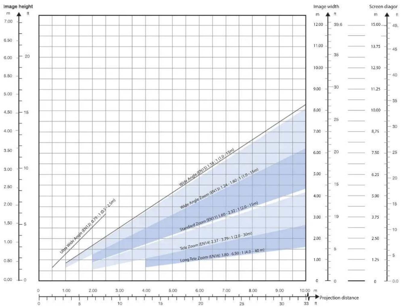
line
| Projection distance (m) | Image height (m) | Screen diagor (m) | | ----------------------- | ---------------- | ----------------- | | 0.0 | 0.0 | 0.0 | | 5.0 | 0.5 | 1.25 | | 10.0 | 1.0 | 2.50 | | 15.0 | 1.5 | 3.75 | | 20.0 | 2.0 | 5.00 | | 25.0 | 2.5 | 6.25 | | 30.0 | 3.0 | 7.50 | | 33.0 | 3.5 | 8.75 | | 33.0 | 4.0 | 10.00 | | 33.0 | 4.5 | 11.25 | | 33.0 | 5.0 | 12.50 | | 33.0 | 5.5 | 13.75 | | 33.0 | 6.0 | 15.00 | | 33.0 | 6.5 | 16.25 | | 33.0 | 7.0 | 17.50 | | 33.0 | 7.5 | 18.75 | | 33.0 | 8.0 | 20.00 | | 33.0 | 8.5 | 21.25 | | 33.0 | 9.0 | 22.50 | | 33.0 | 9.5 | 23.75 | | 33.0 | 10.0 | 25.00 | | 33.0 | 10.5 | 26.25 | | 33.0 | 11.0 | 27.50 | | 33.0 | 11.5 | 28.75 | | 33.0 | 12.0 | 30.00 | | 33.0 | 12.5 | 31.25 | | 33.0 | 13.0 | 32.50 | | 33.0 | 13.5 | 33.75 | | 33.0 | 14.0 | 35.00 | | 33.0 | 14.5 | 36.25 | | 33.0 | 15.0 | 37.50 | | 33.0 | 15.5 | 38.75 | | 33.0 | 16.0 | 40.00 | | 33.0 | 16.5 | 41.25 | | 33.0 | 17.0 | 42.50 | | 33.0 | 17.5 | 43.75 | | 33.0 | 18.0 | 45.00 | | 33.0 | 18.5 | 46.25 | | 33.0 | 19.0 | 47.50 | | 33.0 | 19.5 | 48.75 | | 33.0 | 20.0 | 50.00 | | 33.0 | 20.5 | 51.25 | | 33.0 | 21.0 | 52.50 | | 33.0 | 21.5 | 53.75 | | 33.0 | 22.0 | 55.00 | | 33.0 | 22.5 | 56.25 | | 33.0 | 23.0 | 57.50 | | 33.0 | 23.5 | 58.75 | | 33.0 | 24.0 | 60.00 | | 33.0 | 24.5 | 61.25 | | 33.0 | 25.0 | 62.50 | | 33.0 | 25.5 | 63.75 | | 33.0 | 26.0 | 65.00 | | 33.0 | 26.5 | 66.25 | | 33.0 | 27.0 | 67.50 | | 33.0 | 27.5 | 68.75 | | 33.0 | 28.0 | 70.00 | | 33.0 | 28.5 | 71.25 | | 33.0 | 29.0 | 72.50 | | 33.0 | 29.5 | 73.75 | | 33.0 | 30.0 | 75.00 | | 33.0 | 30.5 | 76.25 | | 33.0 | 31.0 | 77.50 | | 33.0 | 31.5 | 78.75 | | 33.0 | 32.0 | 80.00 | | 33.0 | 32.5 | 81.25 | | 33.0 | 33.0 | 82.50 | | 33.0 | 33.5 | 83.75 | | 33.0 | 34.0 | 85.00 | | 33.0 | 34.5 | 86.25 | | 33.0 | 35.0 | 87.50 | | 33.0 | 35.5 | 88.75 | | 33.0 | 36.0 | 90.00 | | 33.0 | 36.5 | 91.25 | | 33.0 | 37.0 | 92.50 | | 33.0 | 37.5 | 93.75 | | 33.0 | 38.0 | 95.00 | | 33.0 | 38.5 | 96.25 | | 33.0 | 39.0 | 97.50 | | 33.0 | 39.5 | 98.75 | | 33.0 | 40.0 | 100.00 | | Note: The image width and screen diagor data are not explicitly provided in the code snippet, so they are represented as a single column in the image table format. **Projection distance (m)***;** *Image height (m): *Ultra Wide Angle (EN12); *Size of *Size of *Value; *Distance of *Value of *Diagonal; *Screen diameter: *Screen diameter.! Lens types and specifications may change without prior notice. For correct lens information please refer to projectiondesign.com/products/lenses
1920 x 1200 (WUXGA)
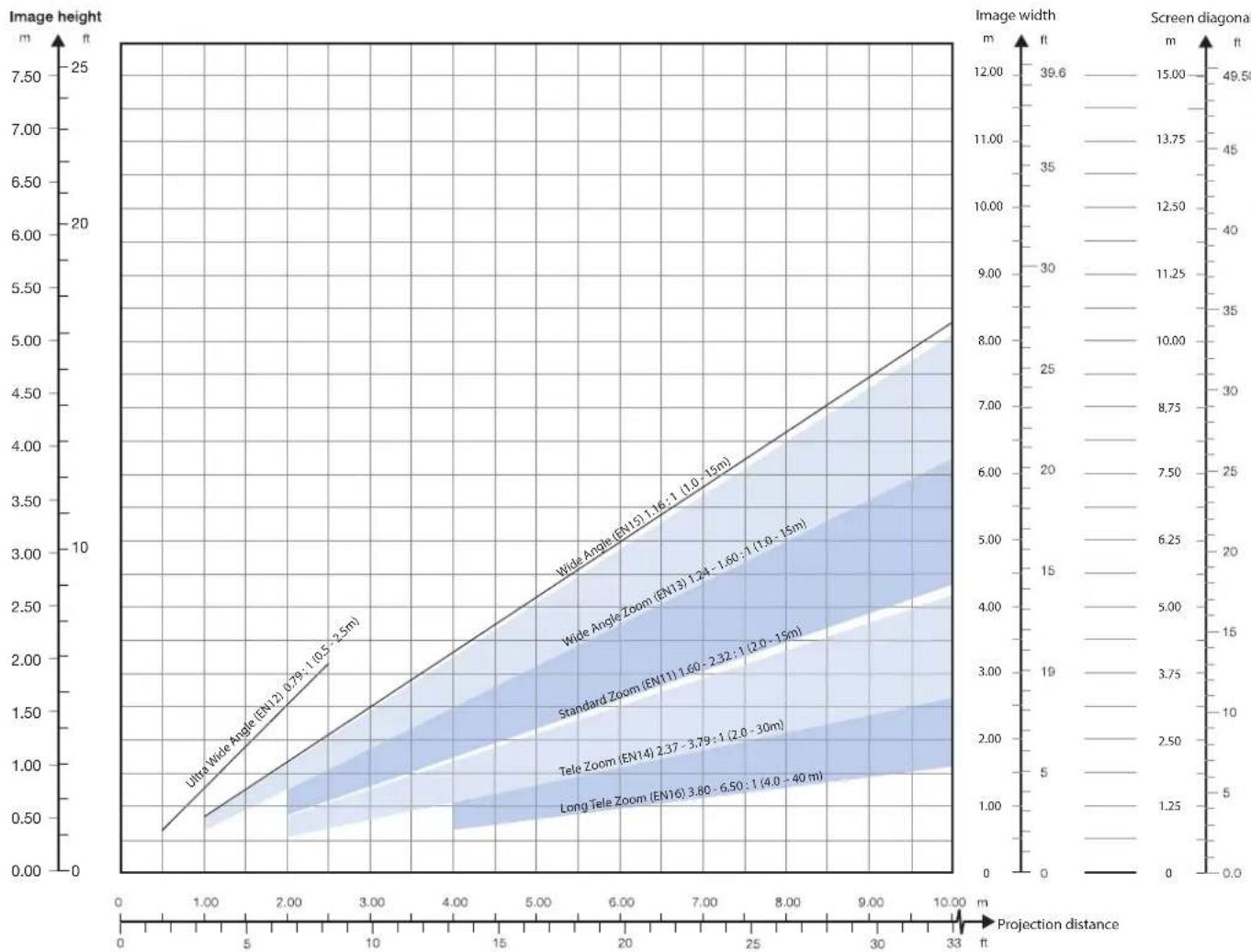
line
| Projection distance | Ultra Wide Angle (EN12) | Wide Angle (EN15) | Wide Zoom (EN19) | Standard Zoom (EN11) | Tele Zoom (EN14) | Long Tele Zoom (EN16) | | ------------------- | ------------------------ | ------------------ | ----------------- | --------------------- | ----------------- | ---------------------- | | 0.5 | 0.79 | 1.16 | 1.24 | 1.60 | 2.37 | 3.80 | | 2.5 | 1.05 | 1.50 | 1.60 | 2.32 | 3.79 | 6.50 | | 4.0 | - | - | - | - | - | - | | 6.0 | - | - | - | - | - | - | | 8.0 | - | - | - | - | - | - | | 10.0 | - | - | - | - | - | - |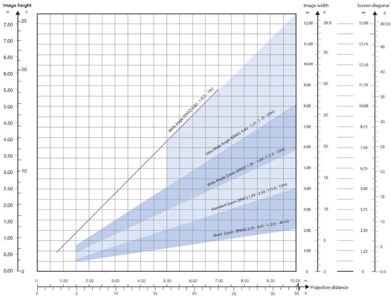
line
| Projection distance (m) | Image height (m) | Screen diagonal (m) | | ------------------------ | ---------------- | -------------------- | | 0.80 | 1.0 | 15.0 | | 1.21 | 1.2 | 13.75 | | 1.69 | 1.69 | 12.5 | | 2.50 | 2.50 | 11.25 | | 4.61 | 4.61 | 10.0 | | 7.0 | 7.0 | 8.75 |5 Advanced setup
5.1 Controlling multiple projectors with remote control ID (RCID)
The remote control can be operated either in 'broadcast mode', or 'individual mode'. When several projectors are in use in an installation, individual control may be convenient. Individual control is available either by wired remote control, using the data-jack, or by using an individual number code. For individual control, first set the individual RC ID code using the projector menu system, see the SETTINGS sub menu. Then, to select a specific projector to control, first press the '*' button in the lower keypad area, then the code as set in the target projector. A code can be in the range '0'..'99'. '0' is reserved for broadcast. To select another target, repeat the process by pressing '*' and a new code. To exit individual control, press '*' twice or press '*' and '0'.
5.2 Protecting the projector with a pin code
The projector may be controlled by a PIN (Personal Identification Number) code. The PIN code is 4 digits, and if the PIN code is activated, you must enter the correct code to unlock the projector. Factory set PIN (1234).
To activate, deactivate or change the PIN code, see the SETTINGS > PIN CODE sub menu.
If an incorrect PIN code is entered, you may try again two times. If you fail three times in a row, a PUK (unlock) code is needed. The PUK code is supplied with the product.
Entering the puk code correctly is the customers responsibility
If you also fail three times with the PUK code, the projector locks up permanently, and can only be unlocked by a special service unlock code.
To access this code, you will need to contact your dealer or a service station. The service unlock code will be generated based on a secure, encrypted number that is produced by the projector itself. The projector will produce a new number every time.
To unlock the projector, proof of ownership must be provided by the customer
5.3 Using dual head input
For extended flexibility to connect high resolution sources with a pixel clock over 165 MHz, the projector is supporting a dual head input mode. In this mode the left and right half of the image can be connected to the DVI 1/DVI 2 or HDMI 1/HDMI 2 interfaces respectively (Figure 6-1).
To enable this mode, go to the menu INSTALLATION > DUAL HEAD SETUP. Side-by-side is the only available option at this time.
| 1 | 2 |
Figure 5-1. Dual input mode
An example of this is feeding a WUXGA (1920 x 1200) 120Hz source with 960 x 1200 - 120Hz source resolutions on each the DVI interfaces.
When enabling this mode, the EDID data on each of the DVI connectors will automatically be changed from WUXGA (1920 x 1200) 120Hz to 960 x 1200 - 120Hz.
For the image to be displayed in this mode, the resolution must be exactly the same on both connectors.
In this mode the two connected sources must have exactly the same timing. A drift in timing between the inputs will result in a visible split in the center of image.
! Some graphic cards have problems with detecting the change from single head to dual head mode. If problems occur, disconnect both signal cables before enabling or disabling the dual mode in the menu.
5.4 Multi-channel 3D synchronization
X-PORT DCC120 has advanced capabilities for handling synchronization of multiple projectors in a 3D installation.
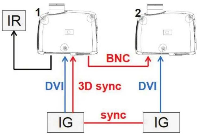
5.4.1 Synchronous frame sequential
A typical synchronous frame sequential 3D setup is shown in Figure 6-2.
flowchart
graph TD
    IR["IR"] -->|BNC| BNC_BNC
    BNC_BNC -->|3D sync| DVI1["DVI"]
    BNC_BNC -->|sync| DVI2["DVI"]
    DVI1 -->|ID| IG1["IG"]
    DVI2 -->|ID| IG2["IG"]
    IG1 -->|ID| ID1["1"]
    IG2 -->|ID| ID2["2"]
Figure 5-2. Synchronous frame sequential 3D
In this case IGs are synchronized and 3D sync from the source is connected from the DIN connector on the IG to the BNC sync-in connector. The source 3D sync is then sent to every projector in the setup. See table below.
| SETTING PROJECTOR 1 | PROJECTOR 2 | |
| 3D Frame sequential Frame | sequential | |
| 3D L/R sync BNC sync-in B | NC sync-in | |
| 3D BNC sync-out signal Pass through Pass through | ||
5.4.2 Asynchronous frame sequential
This mode is not supported.
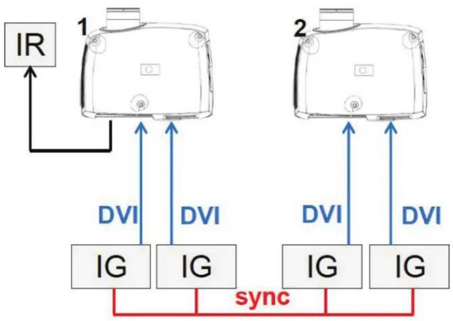
5.4.3 Synchronous side-by-side
Figure 6-3 illustrates a typical synchronous side-by-side 3D setup.
flowchart
graph TD
    A["IR"] --> B["1"]
    B --> C["2"]
    C --> D["DVI"]
    C --> E["DVI"]
    C --> F["DVI"]
    C --> G["DVI"]
    B --> H["IG"]
    C --> I["IG"]
    D --> J["sync"]
    E --> J
    F --> J
    G --> J
    style J fill:#f9f,stroke:#333
Figure 5-3. Synchronous side-by-side setup
Since the sources are synchronized in this setup, synchronization management is not required in the projector. The table below shows the recommended system settings.
| SETTING PROJECTOR 1 | PROJECTOR 2 | |
| 3D Side-by-side Side-by-side | ||
| 3D L/R sync Source Source | ||
| 3D BNC sync-out signal Not used, but can be set to 3D glass sync. | Not used, but can be set to 3D glass sync. | |
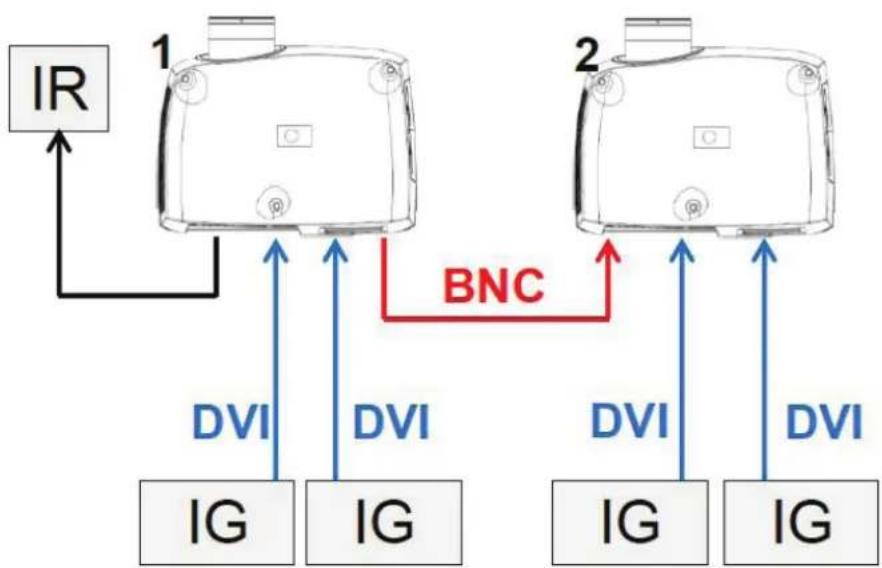
5.4.4 Asynchronous side-by-side
In asynchronous side-by-side 3D, the projectors utilize the BNC sync-in and sync-out connectors to distribute a system wide display sync. This display sync is used by all projectors to perform frame rate conversion on the input signals if necessary. Figure 6-4 illustrates this setup.
flowchart
graph TD
    A["1"] -->|BNC| B["2"]
    B -->|DVI| C["IG"]
    B -->|DVI| D["IG"]
    B -->|DVI| E["IG"]
    style A fill:#f9f,stroke:#333
    style B fill:#f9f,stroke:#333
    style C fill:#ccf,stroke:#333
    style D fill:#ccf,stroke:#333
    style E fill:#ccf,stroke:#333
Figure 5-4. Asynchronous side-by-side setup
As seen in Figure 6-4, an extra cable is connected between BNC sync-out on projector 1 and BNC sync-in on projector 2. In this setup the projectors need the settings in the table below to send/utilize the display sync correctly.
| SETTING PROJECTOR 1 | PROJECTOR 2 | |
| 3D Side-by-side Side-by-side | ||
| 3D L/R sync Source BNC sync-in | ||
| 3D BNC sync-out signal 3D | display L/R sync Pass through | |
5.5 Setting custom color space and digital level
The projector will automatically try to set the correct color space and digital drive level based on information from the source.
To manually override the automatically detected color space and digital level go to menu entry PICTURE -> ADVANCED. Set the "digital color space and level" to manual and select your color space and digital drive level.
5.6 Disabling IR receivers
The projector has 3 IR receivers as shown in chapter "4.1 Overview".
These receivers can be individually disabled if necessary. Go to menu entry INSTALLATION > IR FRONT / IR REAR to disable the receivers.
5.7 Controlling screens with triggers
The projector has two programmable triggers with 3.5 mm mini-jack connectors. These can be used to enable or disable screens, curtains or other peripheral equipment.
To change trigger settings, go to menu entry INSTALLATION > TRIGGER
By default:
- Trigger 1 is set to control a screen depending on whether projector is powered on or not.
- Trigger 2 is set to control a screen depending on the aspect ratio of currently active source.
Both triggers can be manually overridden both in the menu system and by using the command and control protocol through RS-232 or LAN.
5.8 Setting aspect trigger behavior
To customize the aspect trigger functionality, go to menu entry INSTALLATION > TRIGGER > ASPECT TRIGGER BEHAVIOR. In this sub-menu it is selectable for which input aspect ratios the trigger will be enabled.
5.9 Automatic power on/off
The projector can be automatically powered on or off by using the internal timer function or DPMS.
5.9.1 Using the timer
The projector features a real-time clock that enables timing control. This means that the projector can be programmed to switch on and off at certain pre-set times during a weekly cycle.
To allow for a flexible schedule, 10 'programs' are available. With each program, you can define the switch on or switch off time for a single day (Monday to Sunday), all work days (Monday through Friday), or week-end (Saturday and Sunday). One, several or all programs can be active at the same time as desired. In this way, a flexible scheme can be established. Observe the 24 hour time format. For more information, see the SETTINGS > TIMER menu.
The following example illustrates a case where the projector turns on at 08:00 in the morning (8 am) and switches off at 20:00 (8 pm) on weekdays (Monday through Friday). Weekends (Saturdays and Sundays), it turns on at 10:00 (10 am) and off at 18:00 (6 pm). VGA is used as the source. For this, four programs are needed, 2 for on and two for off.
5.9.2 Using DPMS (Display Power Management Signaling)
The projector is enabled for DPMS (Display Power Management Signaling). When enabled, the projector will automatically switch to standby mode after a specified time if there is no valid source present at its inputs. When a valid source is reconnected, the projector will start up again.
To enable or disable DPMS, go to menu entry SETTINGS > DPMS. The desired DPMS timeout is set in the DPMS > DPMS TIMEOUT menu entry.
DPMS is disabled by default.
5.10 Disabling LED indicators
In certain installations it may desirable to completely disable the LED indicator in the keypad of the projector. To disable the LED indicators, go to menu entry SETTINGS > LED INDICATORS MUTE.
If the LED indicators are enabled, the timeout period can be set in the menu under SETTINGS > BACKLIGHT TIMEOUT.
5.11 Setting the background color
The background color displayed when the projector is searching for a source can be set to a set of predefined colors. Go to menu entry SETTINGS > BACKGROUND to set the desired color. Default is black. Setting OSD menu timeout
If the OSD menu is open and not used for a defined period of time, it will automatically be disabled. The default time is 30 seconds. This timeout interval can be controlled from 5 seconds to 60 seconds. The timeout can also be set to "never" for the OSD menu to never time out. Go to menu entry SETTINGS > MENU TIMEOUT to change this setting.
5.12 Selecting the startup logo
When the projector is starting up, a logo is displayed in the entire image. The logo can also be set to "black" if it is desirable to disable the manufacturers default logo. Go to menu entry SETTINGS > SPLASH to change this setting.
5.13 Setting OSD menu timeout
If the OSD menu is open and not used for a defined period of time, it will automatically be disabled. The default time is 30 seconds. This timeout interval can be controlled from 5 seconds to 60 seconds. The timeout can also be set to "never" for the OSD menu to never time out. Go to menu entry SETTINGS > MENU TIMEOUT to change this setting.
5.14 Selecting the startup logo
When the projector is starting up, a logo is displayed in the entire image. The logo can also be set to "black" if it is desirable to disable the manufacturers default logo. Go to menu entry SETTINGS > SPLASH to change this setting.
6 Optimising the picture
The projector has power features for picture optimization. This chapter describes details in using these features. All color calibration is done using projectiondesign's proprietary Real-Color™ solution.
6.1 Calibration data
All projectiondesign projectors are measured and calibrated with high precision equipment at the factory for the best out-of-box experience. Over the lifetime of the lamps the characteristics of the projector might change slightly. The same applies when replacing lamps.
6.1.1 Updating RealColor™ calibration data
For accurate results with the RealColor ^™ system, accurate measurement data is required.
RealColor™ calibration data can be found under the menu entry PICTURE > CALIBRATION > REALCOLOR CALIBRATION > MEASURED VALUES
X, Y and relative luminance values for red, green, blue, white and BrilliantColor™ 1 is entered in this menu. The BrilliantColor™ should all be set to 0.000 for the VizSim (RGBRGB) color wheel. All values can also be updated using the communications protocol over RS-232 or LAN.

Before setting these values, it is important to select the desired BrilliantColor ^™ setting. Go to menu entry PICTURE > REALCOLOR > BRILLIANTCOLOR to select the desired BrilliantColor ^™ look.
Measurements must be done on the built in test patterns. This is in particularly important for the BrilliantColor™ 1 test pattern since it is impossible to generate this pattern correctly using a computer source. In the user menu these patterns can be accessed through PICTURE > CALIBRATION > REALCOLOR CALIBRATION > CALIBRATION TESTIMAGE. Use the arrow keys to cycle through the images.

Performing a factory reset of the projector will restore the measured values to the values measured in the factory.

When measuring data, a high quality measurement instrument is highly recommended for accurate results. Spectrometers (like PhotoResearch PR-655) are preferred.

For an easier calibration procedure, automated calibration can be achieved using projectiondesign's software package ProNet. A license for the calibration software package of ProNet must be purchased separately.
6.2 Working with RealColor™
6.2.1 Setting the BrilliantColor™ correctly
The BrilliantColor™ setting is used to control how color boost is applied in the image. It can operate in four modes:
- Computer Native (Default): This give max brightness and color boost. Recommended for non-video applications, like CAD and visualization.
- Computer Balanced: Gives the same brightness as Computer Native, but has a less aggressive color boost profile.
- Video Native: Gives less brightness than computer, but will appear with significantly less noise in video content.
- Video Balanced: Same brightness as Video Native, but with a smoother color boost profile.
- Off: Only recommend for applications requiring a pure red, green, blue mix of colors. No secondary color or white are added to the mix.
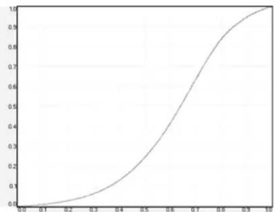
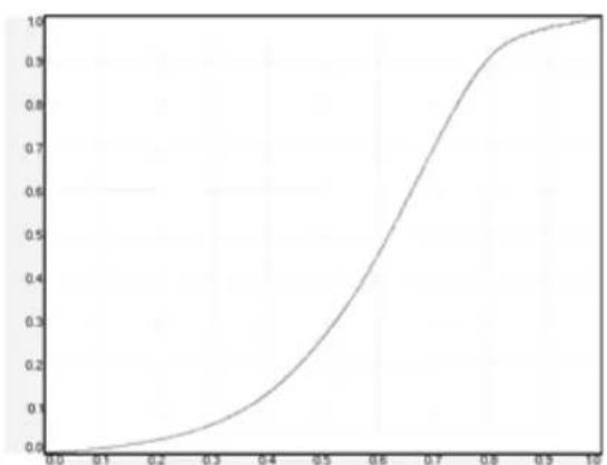
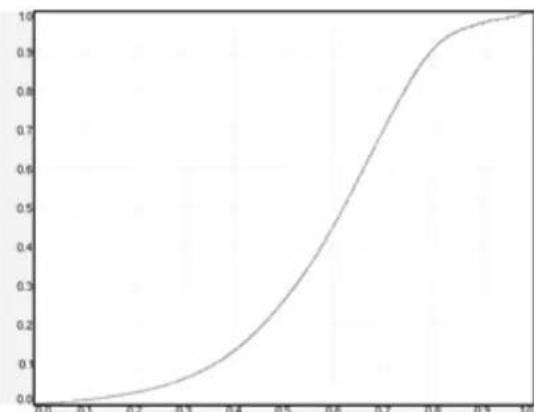
6.2.2 Gamma
The projector features a set of 6 built in gamma curves: Film 2.2, Film 2.8, Video 1, Video 2, Computer 1, Computer 2. The different gamma curves are displayed below.

The names of the curves are descriptive for their recommended use. Use any of the computer curves for video applications will results in significant image noise.
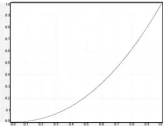
line
| x | y | | ---- | ---- | | 0.0 | 0.0 | | 0.1 | 0.05 | | 0.2 | 0.1 | | 0.3 | 0.15 | | 0.4 | 0.2 | | 0.5 | 0.3 | | 0.6 | 0.4 | | 0.7 | 0.55 | | 0.8 | 0.7 | | 0.9 | 0.85 | | 1.0 | 1.0 |Figure 6-1. Film 2.2 gamma
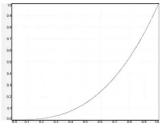
line
| x | y | | ---- | ----- | | 0.0 | 0.0 | | 0.1 | 0.0 | | 0.2 | 0.0 | | 0.3 | 0.05 | | 0.4 | 0.1 | | 0.5 | 0.2 | | 0.6 | 0.3 | | 0.7 | 0.45 | | 0.8 | 0.6 | | 0.9 | 0.8 | | 1.0 | 1.0 |Figure 6-2. Film 2.8 gamma
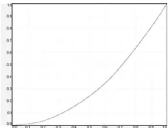
line
| x | y | | ---- | ---- | | 0.0 | 0.0 | | 0.1 | 0.05 | | 0.2 | 0.1 | | 0.3 | 0.15 | | 0.4 | 0.2 | | 0.5 | 0.25 | | 0.6 | 0.35 | | 0.7 | 0.5 | | 0.8 | 0.65 | | 0.9 | 0.85 | | 1.0 | 1.0 |Figure 6-3. Video 1 gamma
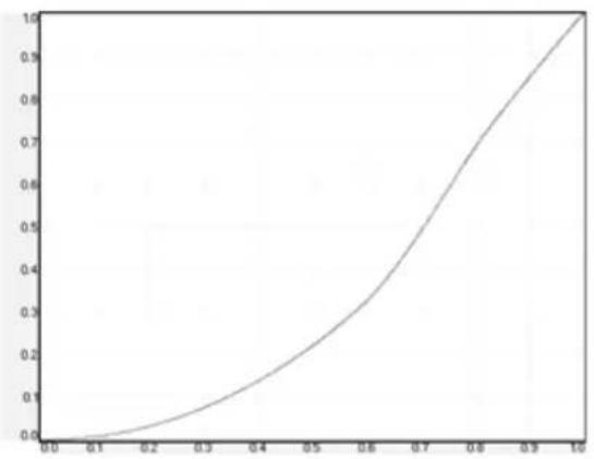
line
| x | y | | ---- | ----- | | 0.0 | 0.0 | | 0.1 | 0.05 | | 0.2 | 0.1 | | 0.3 | 0.15 | | 0.4 | 0.2 | | 0.5 | 0.3 | | 0.6 | 0.4 | | 0.7 | 0.55 | | 0.8 | 0.7 | | 0.9 | 0.85 | | 1.0 | 1.0 |Figure 6-4. Video 2 gamma
line
| x | y | | ---- | ----- | | 0.0 | 0.0 | | 0.1 | 0.05 | | 0.2 | 0.1 | | 0.3 | 0.2 | | 0.4 | 0.35 | | 0.5 | 0.5 | | 0.6 | 0.7 | | 0.7 | 0.85 | | 0.8 | 0.95 | | 0.9 | 0.98 | | 1.0 | 1.0 |Figure 6-5. Computer 1 gamma
line
| x | y | | ---- | ----- | | 0.0 | 0.0 | | 0.1 | 0.05 | | 0.2 | 0.1 | | 0.3 | 0.2 | | 0.4 | 0.35 | | 0.5 | 0.5 | | 0.6 | 0.7 | | 0.7 | 0.85 | | 0.8 | 0.95 | | 0.9 | 0.98 | | 1.0 | 1.0 |Figure 6-6. Computer 2 gamma
6.2.3 RealColor™ operating modes
Before any color correction is applied to the image, the feature must be enabled. Go to menu entry PICTURE > REALCOLOR > COLOR CORRECTION to enable RealColor™.
RealColor ^TM can operate in 3 modes:
• Color temperature/white point correction only.
- Red, Green, Blue, White correction. In this mode optimal color coordinates for Cyan, Magenta and Yellow will be computed automatically.
- Red, Green, Blue, Cyan, Magenta, Yellow, White. In this mode color points and intensity for each color can be manipulated separately.
To change the RealColor™ mode, please go the menu entry PICTURE > REALCOLOR > DESIRED VALUES > DESIRED COORDS MODE.
6.2.4 Setting a white point or color temperature
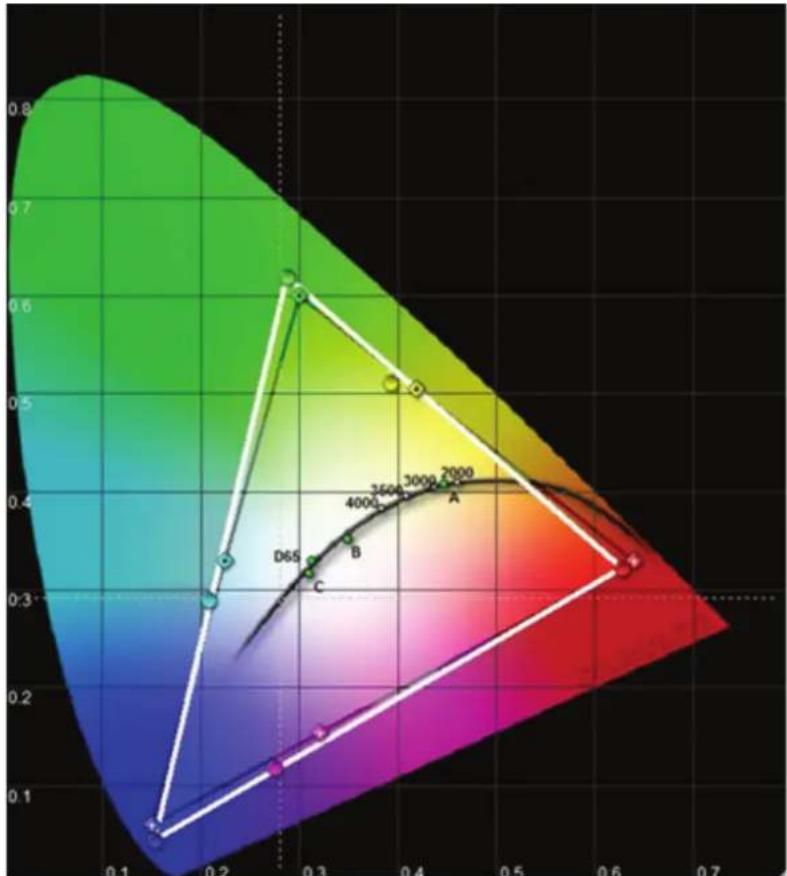
After enabling RealColor™, set the color temperature in the menu entry PICTURE > REAL-COLOR > COLOR TEMPERATURE. Values between 3200K and 9300K can be selected. These color temperatures are tracking the "black body curve"- the black curved line in the center of CIE Chart in Figure 7-7. The default is the D65 illuminant at 6500K.
radar
| Label | Value | |-------|-------| | D65 | 0.3 | | B | 0.35 | | 4000 | 0.38 | | 2600 | 0.4 | | 3000 | 0.42 | | 2000 | 0.45 |Figure 6-7. CIE Chart with the black body curve
The white point can also be set to a custom value defined by an x, y coordinate not linked to the black body curve. Go to menu entry PICTURE > REALCOLOR > X-COORDINATE and PICTURE > REALCOLOR > Y-COORDINATE to change the white point.
6.2.5 Defining the system color gamut
All colors visible to the eye are defined by CIE Chart in Figure 7-7. The boundary of the colors the projector can display is called the system color gamut. The white triangle in Figure 7-7 is an example of a system color gamut. By default the projector has the widest possible system gamut, which is limited by the color wheel selected for the system. The VizSim color wheel has the widest color gamut and the High Brightness color wheel has the smallest.

The system color gamut cannot be expanded outside color gamut defined by the color wheel.
It may be desirable to change the system color gamut of the projector to:
- Color match multiple projectors.
- Meet defined color standards, like REC 709.
- Create a special "look" to the image.
Before the system color gamut can be change the desired RealColor™ mode has to be defined. To change the RealColor™ mode, please go the menu entry PICTURE > REAL-COLOR > DESIRED VALUES > DESIRED COORDS MODE.
RealColor™ has to be enabled for the desired system gamut to be applied. Go to menu entry PICTURE > REALCOLOR > COLOR CORRECTION to enable RealColor™.
After RealColor ^™ is enabled and the desired color correction mode is selected, please go the menu entry PICTURE > REALCOLOR > DESIRED VALUES to change the color points to the your desired system color gamut.

For graphical visualization of the system color gamut and easy color management for a single or multiple projectors, the ProNet software package could be used. A license for the calibration software package of ProNet must be purchased separately.
7 Maintenance
7.1 Software upgrades
In order to upgrade your projector, please follow the method and sequence described below.
- You will need a USB memory stick set up with a FAT-file system to perform this upgrade
- Access the upgrade software from the following web-address; www.projectiondesign.com
- Download and save the firmware.zip-file to your PC desktop
- Unzip and extract the firmware file to the root of a memory stick PS! Important that the USB is safely removed from computer, using the eject function on your PC.
- Set the projector in standby mode
- Insert the memory stick in the projector and wait for a few seconds
- The LCD display will indicate that it has detected an upgrade file on the memory stick. Wait a few seconds while the file is validated
- Remove the memory stick when the LCD display instructs you to do so.
- Do not remove the power cord while the upgrade is still in progress
- The projector may restart several times during the upgrade
The upgrade has finished successfully when the ordinary LCD display returns.
Please refer to our website to download the required files or seek other information
7.2 Lamp replacement (UHP units only)
The LAMP indicators on the keypad will turn red when lamp life expires or if the lamp fails.
Change the lamp when lifetime expires. Always replace lamp with the same type and rating. USE ORIGINAL LAMPS ONLY.
The lamp includes an electronic lamp timer that is tracking the life time of the lamp.
Allow lamp to cool down before changing. One lamp may be changed while the other lamp is operating (hot-swap).
Release the screw (LAMP 1) or (LAMP 2) depending on which lamp that needs to be replaced.
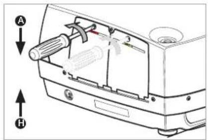
Be careful not to touch the protective glass when replacing the lamp, this may cause the protective glass to overheat and break while in use.
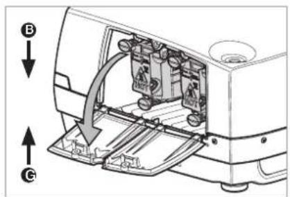
Be extremely careful when removing the lamp module. In the unlikely event that the bulb ruptures, small glass fragments may be generated. The lamp module is designed to contain these fragments, but use caution when removing the lamp module.
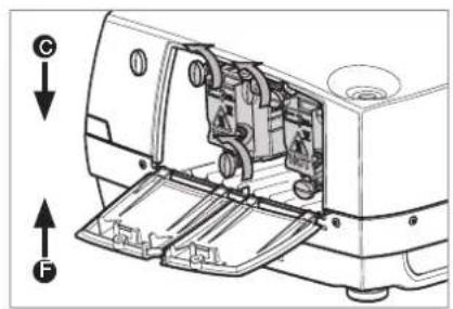
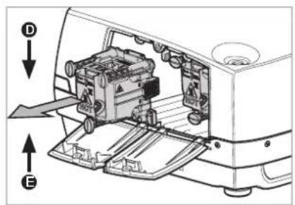
A Open the lamp lid(s).
B Turn the three locking screws a quarter turn anti-clockwise.
C Pull the lamp out.
D Replace with a new lamp in reverse order.
E Insert a new lamp. Observe the guide pins.
F Turn the tree locking screws a quarter turn clockwise.
G Close the lamp lid.
H Turn the locking screw clockwise.
In the unlikely event of a lamp rapture, a limited amount of mercury vapor may be emitted into the room. To avoid inhailing this mercury vapor (which is toxic, and can be harmful for lungs and nervous system) the room should be thoroughly ventilated for a period of at least 30 minutes. There are no known health hazards from exposure to lamps that are intact and which are used within an enclosed fixture. No adverse effects are expected from occasional exposure to broken lamps. As a matter of good practise, avoid prolonged or frequent exposure to lamps unless there is adequate ventilation. The major hazard from broken lamps is the possibility of sustaining glass cuts.
8 Technical specifications
8.1 Product details
technology single chip DMD™ (Digital Micromirror Device™)
concept sealed, all-glass optical design with lens shift
available resolutions WQXGA (2560 x 1600)
WUXGA (1920 x 1200)
1080p (1920 x 1080)
connectivity please refer to section 4.3 Connectivity for complete list
dimensions (dwh) 376 x 510 x 223 mm (ex. lens)
weight about 12.6 kg (ex. lens)
environmental RoHS, WEEE
power requirements 8.4A -100-240V 50-60Hz
<1050W power consumption (UHP)
<325W power consumption (LED)
BTU/hr <2750 (UHP) / <1100 (LED)
operating temperature 0 - 40°C / 32 - 104°F, 0 - 1500 m
0 - 35°C / 32 - 95°F, 1500 - 3000 m
conformances CE, FCC Class A and cCSAus
UHP lamp 2 x 300W UHP™
lamp life 2000/2500 hrs full/eco (5000 hrs in auto switch eco mode*)
lamp part no. 400-0500-00
LED lamp LED illumination
lamp life Up to 100000 hours (Full power)
Up to 100000 hours (Eco mode)
lamp part no. n/a
* Option in lamp sub menu: One lamp will be lit at the time and the projector will automatically switch between the lamps in a specified interval (1hr to 24hr).

For a more extensive and up to date overview of technical specifications, please refer to the product page on our home page.
1 本用户手册目录
1 简介 7
1.1 谢谢您
1.2 特征
1.3 本文档中使用的符号
2 安全说明 9
2.1 安全性
2.2 常规警告
natural_image
Illustration of a projector with warning symbols (no text or labels)natural_image
White projector with black lens and gray frame (no visible text or symbols)电源线(不同国家/地区的电源线有区别)
遥控器
用户文档
投影机的其他配件:
DVI 线缆
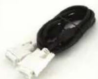
图 4-8. 顶层 OSD 菜单
natural_image
Technical line drawing of a mechanical component with a circular end and arrow indicator (no text or symbols)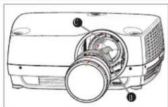
natural_image
Illustration of a projector with a circular dial and control knob (no text or symbols)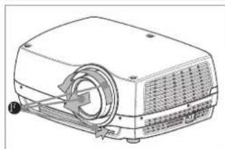
natural_image
Line drawing of a projector device with fan and control panel (no text or symbols)5.2 调节屏幕上的图像尺寸和位置
图 5-1. 图像尺寸和位置调节
5.3 灯泡运作
natural_image
Technical line drawing of a mechanical bracket or support structure (no text or symbols)图 5-3. 吊装支架罩
5.5.1 连接吊装支架罩
如需连接吊装支架罩,请遵循以下步骤:
natural_image
Technical line drawing of a device rear panel with connectors and ports (no text or symbols)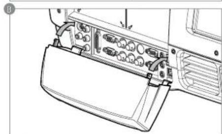
natural_image
Technical line drawing of a mechanical component with ports and connectors (no text or symbols)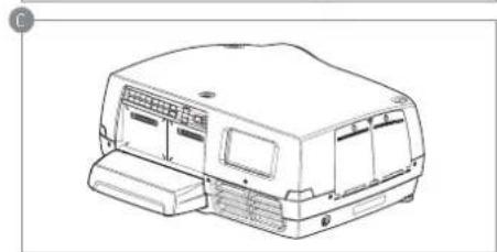
natural_image
Line drawing of a vehicle chassis with front panel and side door (no text or symbols)5.6 连接和电缆
line
| Projection distance (m) | Image height (m) | Screen diagonal (m) | Resolution (m) | | ----------------------- | ---------------- | -------------------- | -------------- | | 0 | 0.5 | 0 | 0 | | 5 | 1.0 | 1.25 | 1 | | 10 | 1.5 | 2 | 2 | | 15 | 2.0 | 3.75 | 3 | | 20 | 2.5 | 5 | 4 | | 25 | 3.0 | 6.25 | 5 | | 30 | 3.5 | 7.5 | 6 | | 33 | 4.0 | 8.75 | 7 | | 33 | 4.5 | 10 | 8 | | 33 | 5.0 | 11.25 | 9 | | 33 | 5.5 | 12.5 | 10 | | 33 | 6.0 | 13.75 | 11 | | 33 | 6.5 | 15 | 12 | | 33 | 7.0 | 16.25 | 13 | | 33 | 7.5 | 17.5 | 14 | | 33 | 8.0 | 18.75 | 15 | | 33 | 8.5 | 20 | 16 | | 33 | 9.0 | 21.25 | 17 | | 33 | 9.5 | 22.5 | 18 | | 33 | 10.0 | 23.75 | 19 | | 33 | 10.5 | 25 | 20 | | 33 | 11.0 | 26.25 | 21 | | 33 | 11.5 | 27.5 | 22 | | 33 | 12.0 | 28.75 | 23 | | 33 | 12.5 | 30 | 24 | | 33 | 13.0 | 31.25 | 25 | | 33 | 13.5 | 32.5 | 26 | | 33 | 14.0 | 33 | 27 | | 33 | 14.5 | | | | 33 | 15.0 | | | | 33 | 15.5 | | | | 33 | 16.0 | | | | 33 | 16.5 | | | | 33 | 17.0 | | | | 33 | 17.5 | | | | 33 | 18.0 | | | | 33 | 18.5 | | | | 33 | 19.0 | | | | 33 | 19.5 | | | | 33 | 20.0 | | | | 33 | 20.5 | | | | 33 | 21.0 | | | | 33 | 21.5 | | | | 33 | 22.0 | | | | 33 | 22.5 | | | | 33 | 23.0 | | | | 33 | 23.5 | | | | 33 | 24.0 | | | | 33 | 24.5 | | | | 33 | 25.0 | | | | Note: The image width values are not explicitly provided in the code snippet, so they are calculated based on the original image and the original image of the original image of the original image of the original image of the original image of the original image of the original image of the original image of the original image of the original image of the original image of the original image of the original image of the original image of the original image of the original image of the original image of the original image of the original image of the original image of the original image of the original image of the original image of the original image of the original image of the original image in each image range (e.g., 'Wide Angle' or 'Ultra Wide Zoom'). The image width is calculated by summing the original image height by a factor of approximately two times the original image height for each image range (e.g., 'Wide Angle' or 'Ultra Wide Zoom'). The screen diagonal is calculated using a formula for the original image and screen diagonal for the original image.6 高级设置
line
| x | y | | ---- | ----- | | 0.0 | 0.0 | | 0.1 | 0.05 | | 0.2 | 0.1 | | 0.3 | 0.15 | | 0.4 | 0.25 | | 0.5 | 0.4 | | 0.6 | 0.6 | | 0.7 | 0.75 | | 0.8 | 0.9 | | 0.9 | 0.95 | | 1.0 | 1.0 |图 7-5. 计算机 1 伽玛
line
| x | y | | ---- | ----- | | 0.0 | 0.0 | | 0.1 | 0.05 | | 0.2 | 0.1 | | 0.3 | 0.2 | | 0.4 | 0.35 | | 0.5 | 0.5 | | 0.6 | 0.7 | | 0.7 | 0.85 | | 0.8 | 0.95 | | 0.9 | 0.98 | | 1.0 | 1.0 |图 7-6. 计算机 2 伽玛
www projectiondesign.com
A 打开灯泡盖。
B 逆时针直角回转三个螺钉。
C 拔出灯泡。
D 按相反的顺序更换新灯泡。
E 插入新灯泡。观察定位销。
9 技术规范
9.1 产品细节
Model certification name:
GP3

- Contents of this User's Guide
- Introduction 6
- Safety Instructions 9
- What's in the box? 13
- Getting to know the projector 15
- Basic setup 21
- Advanced setup 35
- Optimising the picture 43
- Maintenance 49
- Technical specifications 51
- Introduction
- Thank you
- Features
- Symbols used in this documentation
- What's in the box?
- The following components are standard delivery:
- Additional accessories available for the projector:
- Safety Instructions
- SAFETY
- GENERAL WARNINGS
- INFORMATION AND WARNING ABOUT POTENTIAL HEALTH ISSUES RELATED TO MERCURY VAPOR (UHP lamps only)
- HEAVY DUTY AND CONTINUOUS USE (UHP lamps only)
- SERVICE PERSONNEL INFORMATION WARNING (UHP lamps only)
- REMOTE CONTROL WARNING
- WARNING SYMBOLS
- FCC
- CANADA
- WEEE INFORMATION
- Turkey RoHS compliance
- Waste Electrical and Electronic Equipment
- Disposal of batteries in the product
- SERVICE INFORMATION
- Getting to know the projector
- Overview
- Indicators
- The status indicator
- Keypad
- Remote control
- Connectivity
- Graphical User Interface (GUI)
- Basic setup
- Lens
- Lens and lens mount
- Switch off all equipment before setting-up for proper function.
- Never run the projector without lens mounted.
- Inserting a lens
- Replacing a lens
- Adjusting on screen image size and position
- Lamp operation
- Projector rotation
- Ceiling mount
- Ceiling mount cover (optional)
- Attaching the ceiling cover
- Connection and cables
- Setting up a video source
- Setting up a computer source
- Connecting command and control interfaces
- Attaching X-PORT™ modules
- Using X-PORT™ modules
- X-PORT DCC120
- 3D formats supported
- X-PORT 3G-SDI
- Connectivity
- Cable Lenghts
- X-PORT HDMI 3D
- Connectivity
- 3D modes supported
- Image alignment
- Setting image orientation
- Using source scan
- Limiting OSD messages
- Changing the language of the menu system
- Identifying system status
- Getting information about the active source
- Using the dual lamp system (UHP models only)
- Configuring 3D (AS3D)
- Image sizes
- Advanced setup
- Controlling multiple projectors with remote control ID (RCID)
- Protecting the projector with a pin code
- Using dual head input
- Multi-channel 3D synchronization
- Synchronous frame sequential
- Asynchronous frame sequential
- Synchronous side-by-side
- Asynchronous side-by-side
- Setting custom color space and digital level
- Disabling IR receivers
- Controlling screens with triggers
- Setting aspect trigger behavior
- Automatic power on/off
- Using the timer
- Using DPMS (Display Power Management Signaling)
- Disabling LED indicators
- Setting the background color
- Selecting the startup logo
- Setting OSD menu timeout
- Selecting the startup logo
- Optimising the picture
- Calibration data
- Updating RealColor™ calibration data
- Working with RealColor™
- Setting the BrilliantColor™ correctly
- Gamma
- RealColor™ operating modes
- Setting a white point or color temperature
- Defining the system color gamut
- Maintenance
- Software upgrades
- Lamp replacement (UHP units only)
- Technical specifications
- Product details
- 本用户手册目录
- 简介 7
- 安全说明 9
- 调节屏幕上的图像尺寸和位置
- 灯泡运作
- 连接吊装支架罩
- 连接和电缆
- 高级设置
- 技术规范
- 产品细节
Brand : Barco
Model : F35
Category : Vidéo-projecteur