
HDX-4K12 - Projector Barco - Free user manual and instructions
Find the device manual for free HDX-4K12 Barco in PDF.


| Product Type | Video Projector |
| Brand | Barco |
| Model | HDX-4K12 |
| Brightness | 12,000 lumens |
| Native Resolution | 4K UHD (3840 x 2160) |
| Contrast Ratio | 1,900:1 (standard) / 2,200:1 (high contrast mode) |
| Brightness Uniformity | 90% |
| Light Source | 2.5 kW Xenon lamp |
| Lamp Life | 1,000 hours typical |
| Lens Shift | Vertical -30% to +120%, Horizontal -40% to +40% |
| Lens Types | TLD+ zoom lenses: 0.8-1.16, 1.16-1.5, 1.5-2.0, 2.0-2.8, 2.8-4.5, 4.5-7.5, 7.5-11.5:1 |
| Color Correction | P7 Realcolor |
| Warping | Direct adjust OSD + Toolset |
| Edge Blending | ScenergiX horizontal and vertical |
| 3D Capability | Active eyewear (optional), passive Infitec, passive circular, triple flash up to 200 Hz |
| Inputs | Dual HDBaseT, HDMI 2.0, DP 1.2, Quad SDI/HDSDI/dual HDSDI/Quad 3G HDSDI/BarcoLink |
| Control | 10/100 Base-T, RJ-45, RS232, DMX512, IR, XLR wired remote |
| Power Consumption | 3,000 W (standby <8 W) |
| Operating Temperature | 0 to 40 °C |
| Dimensions (W x L x H) | 475 x 725 x 382 mm (18.70" x 28.54" x 14.96") |
| Weight | 50 kg (110 lbs) |
| Safety Features | Hazard distance calculation, lens safety cable, interlock, emergency stop |
| Warranty | 3 years standard |
Frequently Asked Questions - HDX-4K12 Barco
User questions about HDX-4K12 Barco
0 question about this device. Answer the ones you know or ask your own.
Ask a new question about this device
Download the instructions for your Projector in PDF format for free! Find your manual HDX-4K12 - Barco and take your electronic device back in hand. On this page are published all the documents necessary for the use of your device. HDX-4K12 by Barco.
USER MANUAL HDX-4K12 Barco
natural_image
Line drawing of a rectangular electronic device with control panel and ports, no visible text or symbolsUserguide
Productrevision
Software version: 1.0.10
Barco NV
President Kennedypark 35, 8500 Kortrijk, Belgium
Phone: +32 56.36.82.11
Fax: +32 56.36.883.86
Support: www.barco.com/en/support
Visit us at the web: www.barco.com
Copyright©
All rights reserved. No part of this document may be copied, reproduced or translated. It shall not otherwise be recorded, transmitted or stored in a retrieval system without the prior written consent of Barco.
Changes
Barco provides this manual 'as is' without warranty of any kind, either expressed or implied, including but not limited to the implied warranties or merchantability and fitness for a particular purpose. Barco may make improvements and/or changes to the product(s) and/or the program(s) described in this publication at any time without notice.
This publication could contain technical inaccuracies or typographical errors. Changes are periodically made to the information in this publication; these changes are incorporated in new editions of this publication.
The latest edition of Barco manuals can be downloaded from the Barco web site w _ww.barco.com or from the secured Barco web site https://www.barco.com/en/signin.
Trademarks
Brand and product names mentioned in this manual may be trademarks, registered trademarks or copyrights of their respective holders. All brand and product names mentioned in this manual serve as comments or examples and are not to be understood as advertising for the products or their manufacturers.
GuaranteeandCompensation
Barco provides a guarantee relating to perfect manufacturing as part of the legally stipulated terms of guarantee. On receipt, the purchaser must immediately inspect all delivered goods for damage incurred during transport, as well as for material and manufacturing faults Barco must be informed immediately in writing of any complaints.
The period of guarantee begins on the date of transfer of risks, in the case of special systems and software on the date of commissioning, at latest 30 days after the transfer of risks. In the event of justified notice of complaint, Barco can repair the fault or provide a replacement at its own discretion within an appropriate period. If this measure proves to be impossible or unsuccessful, the purchaser can demand a reduction in the purchase price or cancellation of the contract. All other claims, in particular those relating to compensation for direct or indirect damage, and also damage attributed to the operation of software as well as to other services provided by Barco, being a component of the system or independent service, will be deemed invalid provided the damage is not proven to be attributed to the absence of properties guaranteed in writing or due to the intent or gross negligence or part of Barco.
If the purchaser or a third party carries out modifications or repairs on goods delivered by Barco, or if the goods are handled incorrectly, in particular if the systems are operated incorrectly or if, after the transfer of risks, the goods are subject to influences not agreed upon in the contract, all guarantee claims of the purchaser will be rendered invalid. Not included in the guarantee coverage are system failures which are attributed to programs or special electronic circuitry provided by the purchaser, e.g. interfaces. Normal wear as well as normal maintenance are not subject to the guarantee provided by Barco either.
The environmental conditions as well as the servicing and maintenance regulations specified in this manual must be complied with by the customer.
FederalCommunicationsCommission(FCCStatement)
This equipment has been tested and found to comply with the limits for a class A digital device, pursuant to Part 15 of the FCC rules. These limits are designed to provide reasonable protection against harmful interference when the equipment is operated in a commercial environment. This equipment generates, uses, and can radiate radio frequency energy and, if not installed and used in accordance with the instruction manual, may cause harmful interference to radio communications. Operation of this equipment in a residential area may cause harmful interference, in which case the user will be responsible for correcting any interference at his own expense
Changes or modifications not expressly approved by the party responsible for compliance could void the user's authority to operate the equipment
EN55022/CISPR22ClassAITE(InformationTechnologyEquipment)
Class A ITE is a category of all other ITE which satisfies the class A ITE limits but not the class B ITE limits. Such equipment should not be restricted in its sale but the following warning shall be included in the instructions for use:
Warning : This is a class A product. In a domestic environment this product may cause radio interference in which case the user may be required to take adequate measures.
Warning : This equipment is compliant with Class A of CISPR 32. In a residential environment this equipment may cause radio interference.
TABLEOFCONTENTS
1. Safety....3
1.1 General considerations.... 3
1.2 Important safety instructions 4
1.3 High Brightness precautions: Hazard Distance (HD) 7
1.4 HD for fully enclosed projection systems 8
1.5 HD in function of the lens Throw Ratio (TR)....9
1.6 Important warnings concerning HDX flight cases 10
2. Installation preparations .... 11
2.1 Installation requirements 11
2.2 Unpacking the projector....12
2.3 Initial inspection....13
2.4 HDX flight case 14
2.5 Projector configurations 14
2.6 Projector air inlets and outlets....18
2.7 Free download of Projector Toolset 18
3. Physical Installation ......21
3.1 Connecting the projector with the power net 21
3.2 Alignment of a table mounted projector....22
3.3 Mounting the bottom carry handler 22
3.4 Mounting the top carry handler....24
3.5 Suspension of the projector with rigging clamps 25
3.6 Alignment of a ceiling mounted projector 27
4. Lenses & Lens selection....29
4.1 Available lenses 29
4.2 Lens selection 30
4.3 Lens installation 31
4.4 Lens removal 33
4.5 Lens safety cable 33
4.6 Scheimpflug adjustment....35
5. Input & Communication....41
5.1 Introduction 41
5.2 Input source connections....41
5.3 Communication connections 43
5.4 LED and Button indication chart 44
6. Getting Started....47
6.1 Functionality overview 47
6.2 Power on projector 48
6.3 Switching to standby 50
6.4 Power off projector 50
6.5 Using the RCU....50
7. GraphicUserInterface (GUI)....53
7.1 Overview 53
7.2 Navigation 53
7.3 Test Patterns....54
8. GUI – Source ....55
8.1 Source Selection 55
8.2 Connector Settings 55
9. GUI - Image ....57
9.1 Setting image levels manually 57
9.2 P7 Realcolor 58
9.3 Setting the output resolution 59
10. GUI – Installation ...... 61
10.1 Configuring the lens 61
10.2 Orientation 62
10.3 Warping 63
10.3.1 About warping....63
10.3.2 Warping – Screen Size 63
10.3.3 Warping - 4 corners adjustment....64
10.4 Lamp illumination....65
11. GUI-System Settings....67
11.1 Communication....67
11.1.1 Introduction to a Network connection 67
11.1.2 Wired IP address set up 68
11.2 Themes 68
11.3 Service Menu 69
11.3.1 Service - Color 69
11.3.2 Service – Statistics....70
11.3.3 Lens Calibration....70
11.4 Reset....71
12. Maintenance....73
12.1 Cleaning the lens 73
12.2 Cleaning the exterior of the projector 73
13. Servicing....75
13.1 Inserting an input module 75
13.2 Removal of the front cover 76
13.3 Mounting the front cover 78
13.4 Removal of the lamp cover 79
13.5 Mounting the lamp cover 80
13.6 Removal of the lamp house 81
13.7 Installation of the lamp house 82
13.8 Replacement of the high density dust filter 83
13.9 Remove and clear metal front filter 84
A. Specifications 87
A.1 Specifications of the HDX-4K20 87
A.2 Dimensions of a HDX....88
A.3 Technical Regulations 89
B. Stacking HDX projectors....91
B.1 Mount stacking points 91
B.2 Stacking HDX projectors 91
B.3 Aligning stacked HDX projectors....94
C. Environmental Information ......97
C.1 Disposal information....97
C.2 Turkey RoHS compliance 97
C.3 Contact information....98
Glossary 99
Index....101
1.SAFETY
Aboutthischapter
Read this chapter attentively. It contains important information to prevent personal injury while installing and using a HDX projector. Furthermore, it includes several cautions to prevent damage to the HDX projector. Ensure that you understand and follow all safety guidelines, safety instructions and warnings mentioned in this chapter before installing the HDX projector. After this chapter, additional "warnings" and "cautions" are given depending on the installation procedure. Read and follow these "warnings" and "cautions" as well.
Clarificationoftheterm“HDX”usedinthisdocument
When referring in this document to the term "HDX" means that the content is applicable for following Barco products:
• HDX 4K
• HDX 4K12
• HDX 4K14
• HDX 4K20 FLEX

Barcoprovidesaguaranteerelatingtoperfectmanufacturingaspartofthelegallystipulatedtermsofguarantee. Observing the specification mentioned in this chapter is critical for projector performance. Neglecting thiscanresultinlossofwarranty.
1.1 General considerations

WARNING: Ensure you understand and follow all the safety guidelines, safety instructions, warnings and cautionsmentionedinthismanual.

WARNING: Beawareofsuspendedloads.

WARNING: Wear a hard hat to reduce the risk of personal injury.

WARNING: Be careful while working with heavy loads.

WARNING: Mind your fingers while working with heavy loads.

CAUTION: High pressure lamp may explode if improperly handled.
Generalsafetyinstructions
• Before operating this equipment please read this manual thoroughly and retain it for future reference.
• Installation and preliminary adjustments should be performed by qualified Barco personnel or by authorized Barco service dealers.
• All warnings on the projector and in the documentation manuals should be adhered to.
• All instructions for operating and use of this equipment must be followed precisely.
• All local installation codes should be adhered to.
Noticeonsafety
This equipment is built in accordance with the requirements of the international safety standards IEC60950-1, EN60950-1, UL60950-1 and CAN/CSA C22.2 No.60950-1, which are the safety standards of information technology equipment including electrical business equipment. These safety standards impose important requirements on the use of safety critical components, materials and insulation, in order to protect the user or operator against risk of electric shock and energy hazard and having access to live parts. Safety standards also impose limits to the internal and external temperature rises, radiation levels, mechanical stability and strength, enclosure construction and protection against the risk of fire. Simulated single fault condition testing ensures the safety of the equipment to the user even when the equipment's normal operation fails.
Usersdefinition
Throughout this manual, the term SERVICE PERSONNEL refers to persons having appropriate technical training and experience necessary to be knowledgeable of potential hazards to which they are exposed (including, but not limited to HIGH VOLTAGE ELECTRIC and ELECTRONIC CIRCUITRY and HIGH BRIGHTNESS PROJECTORS) in performing a task, and of measures to minimize the potential risk to themselves or other persons. The term USER and OPERATOR refers to any person other than SERVICE PERSONNEL, AUTHORIZED to operate professional projection systems.
A HDX projector is intended "FOR PROFESSIONAL USE ONLY" by AUTHORIZED PERSONNEL familiar with potential hazards associated with high voltage, high intensity light beams, ultraviolet exposure and high temperatures generated by the lamp and associated circuits. Only qualified SERVICE PERSONNEL, knowledgeable of such risks, are allowed to perform service functions inside the product enclosure.
1.2 Important safety instructions
Topreventtheriskofelectricalshock
• This product should be operated from a mono phase AC power source.
- This apparatus must be grounded (earthed) via the supplied 3 conductor AC power cable. If none of the supplied power cables are the correct one, consult your dealer.
If you are unable to insert the plug into the outlet, contact your electrician to replace your obsolete outlet. Do not defeat the purpose of the grounding-type plug.
- Do not allow anything to rest on the power cord. Do not locate this product where persons will walk on the cord. To disconnect the cord, pull it out by the plug. Never pull the cord itself.
- Use only the power cord supplied with your device. While appearing to be similar, other power cords have not been safety tested at the factory and may not be used to power the device. For a replacement power cord, contact your dealer.
- Do not operate the projector with a damaged cord. Replace the cord.
Do not operate the projector if the projector has been dropped or damaged - until it has been examined and approved for operation by a qualified service technician.
- Position the cord so that it will not be tripped over, pulled, or contact hot surfaces.
- If an extension cord is necessary, a cord with a current rating at least equal to that of the projector should be used. A cord rated for less amperage than the projector may overheat.
- Never push objects of any kind into this product through cabinet slots as they may touch dangerous voltage points or short out parts that could result in a risk of fire or electrical shock.
- Do not expose this projector to rain or moisture.
- Do not immerse or expose this projector in water or other liquids.
- Do not spill liquid of any kind on this projector.
- Should any liquid or solid object fall into the cabinet, unplug the set and have it checked by qualified service personnel before resuming operations.
• Do not disassemble this projector, always take it to an authorized trained service person when service or repair work is required.
• Do not use an accessory attachment which is not recommended by the manufacturer.
• Lightning - For added protection for this video product during a lightning storm, or when it is left unattended and unused for long periods of time, unplug it from the wall outlet. This will prevent damage to the device due to lightning and AC power-line surges.
Topreventpersonalinjury
- Isolate electrically before replacing the lamp or lamp house. Caution: Hot lamp (house).
• Caution: High pressure lamp may explode if improperly handled. Refer servicing to qualified service personnel.
• To prevent injury and physical damage, always read this manual and all labels on the system before inserting the lamp casing, connecting to the wall outlet or adjusting the projector.
• To prevent injury, take note of the weight of the projector. Minimum 2 persons are needed to carry the projector.
• To prevent injury, ensure that the lens and all covers are correctly installed. See installation procedures.
• Warning: high intensity light beam. NEVER look into the lens! High luminance could result in damage to the eye. - Warning: extremely high brightness lamps: This projector uses extremely high brightness lamps. Never attempt to look directly into the lens or at the lamp. If the projection distance is less than 6 meter, any person needs to be at least 4 meters away from the projected image. Avoid close range reflection of the projected image on any reflecting surface (such as glass, metal, ...) . When operating the projector, we strongly recommend wearing suitable safety glasses.
• Before attempting to remove any of the projector's covers, you must turn off the projector and disconnect from the wall outlet.
- When required to switch off the projector, to access parts inside, always disconnect the power cord from the power net.
- The power input at the projector side is considered as the disconnect device. When required to switch off the projector, to access parts inside, always disconnect the power cord at the projector side. In case the power input at the projector side is not accessible (e.g. ceiling mount), the socket outlet supplying the projector shall be installed nearby the projector and be easily accessible, or a readily accessible general disconnect device shall be incorporated in the fixed wiring.
- Never stack more than 2 HDX projectors in a hanging configuration (truss) and never stack more than 3 HDX projectors in a base stand configuration (table mount).
- When using the projector in a hanging configuration, always mount 2 safety cables. See installation manual for the correct use of these cables.
- Do not place this equipment on an unstable cart, stand, or table. The product may fall, causing serious damage to it and possible injury to the user.
- It is hazardous to operate without lens or shield. Lenses, shields or ultra violet screens shall be changed if they have become visibly damaged to such an extent that their effectiveness is impaired. For example by cracks or deep scratches.
- Warning: Protection from ultraviolet radiation: Do not look directly in the light beam. The lamp contained in this product is an intense source of light and heat. One component of the light emitted from this lamp is ultraviolet light. Potential eye and skin hazards are present when the lamp is energized due to ultraviolet radiation. Avoid unnecessary exposure. Protect yourself and your employees by making them aware of the hazards and how to protect themselves. Protecting the skin can be accomplished by wearing tightly woven garments and gloves. Protecting the eyes from UV can be accomplished by wearing safety glasses that are designed to provide UV protection. In addition to the UV, the visible light from the lamp is intense and should also be considered when choosing protective eye wear.
- Exposure to UV radiation: Some medications are known to make individuals extra sensitive to UV radiation. The American Conference of Governmental Industrial Hygienists (ACGIH) recommends occupational UV exposure for an-8 hour day to be less than 0,1 micro-watts per square centimeters of effective UV radiation. An evaluation of the workplace is advised to assure employees are not exposed to cumulative radiation levels exceeding these government guidelines. The exposer of this UV radiation is allowed for only 1 hour per day for maintenance and service persons.
- Cooling liquid circuit. The projector contains a cooling circuit filled with Blue antifreeze diluted (1/3 ethanediol – 2/3 Demi water).
When the cooling circuit leaks, switch off the device and contact a service technician.
The liquid is not for household use. Keep out of reach of children. Harmful by oral intake. Avoid exposure to pregnant women. Avoid contact with eyes, skin and clothing. Avoid inhale of the noxious fumes.
- When the projector is mounted above persons, mount always a lens safety cable.
Topreventfirehazard
- Do not place flammable or combustible materials near the projector!
- Barco large screen projection products are designed and manufactured to meet the most stringent safety regulations. This projector radiates heat on its external surfaces and from ventilation ducts during normal operation, which is both normal and safe. Exposing flammable or combustible materials into close proximity of this projector could result in the spontaneous ignition of that material, resulting in a fire. For this reason, it is absolutely necessary to leave an “exclusion zone” around all external surfaces of the projector whereby no flammable or combustible materials are present. The exclusion zone must be not less than 40 cm (16") for all DLP projectors. The exclusion zone on the lens side must be at least 5 m. Do not cover the projector or the lens with any material while the projector is in operation. Keep flammable and combustible materials away from the projector at all times. Mount the projector in a well ventilated area away from sources of ignition and out of direct sun light. Never expose the projector to rain or moisture. In the event of fire, use sand, CO _2 or dry powder fire extinguishers. Never use water on an electrical fire. Always have service performed on this projector by authorized Barco service personnel. Always insist on genuine Barco replacement parts. Never use non-Barco replacement parts as they may degrade the safety of this projector.
- Slots and openings in this equipment are provided for ventilation. To ensure reliable operation of the projector and to protect it from overheating, these openings must not be blocked or covered. The openings should never be blocked by placing the projector too close to walls, or other similar surface. This projector should never be placed near or over a radiator or heat register. This projector should not be placed in a built-in installation or enclosure unless proper ventilation is provided.
• Projection rooms must be well ventilated or cooled in order to avoid build up of heat. - Let the projector cool down completely before storing. Remove cord from the projector when storing.
• Heat sensitive materials should not be placed in the path of the exhausted air or on the lamp house.
Topreventprojectordamage
• This projector has been designed for use with a specific lamp (house) type. See installation instructions for its correct type.
- The air filters of the projector must be cleaned or replaced on regular base (a "clean" booth would be monthly-minimum). Neglecting this could result in disrupting the air flow inside the projector, causing overheating. Overheating may lead to the projector shutting down during operation.
- The projector must always be installed in a manner which ensures free flow of air into its air inlets and unimpeded evacuation of the hot air from its cooling system.
- In order to ensure that correct airflow is maintained, and that the projector complies with Electromagnetic Compatibility (EMC) requirements, it should always be operated with all of its covers in place.
- Slots and openings in the cabinet are provided for ventilation. To ensure reliable operation of the product and to protect it from overheating, these openings must not be blocked or covered. The openings should never be blocked by placing the product on a bed, sofa, rug, or other similar surface. This product should never be placed near or over a radiator or heat register. The device should not be placed in a built-in installation or enclosure unless proper ventilation is provided.
- Ensure that nothing can be spilled on, or dropped inside the projector. If this does happen, switch off and unplug the mains supply immediately. Do not operate the projector again until it has been checked by qualified service personnel.
- Do not block the projector cooling fans or free air movement around the projector. Loose papers or other objects may not be nearer to the projector than 10 cm (4") on any side.
- Do not use this equipment near water.
- Special care for Laser Beams: Special care should be used when DLP projectors are used in the same room as high power laser equipment. Direct or indirect hitting of a laser beam on to the lens can severely damage the Digital Mirror Devices™ in which case there is a loss of warranty.
- Never place the projector in direct sun light. Sun light on the lens can severely damage the Digital Mirror Devices™ in which case there is a loss of warranty.
- Save the original shipping carton and packing material. They will come in handy if you ever have to ship your equipment. For maximum protection, repack your set as it was originally packed at the factory.
- Unplug this product from the wall outlet before cleaning. Do not use liquid cleaners or aerosol cleaners. Use a damp cloth for cleaning. Never use strong solvents, such as thinner or benzine, or abrasive cleaners, since these will damage the cabinet. Stubborn stains may be removed with a cloth lightly dampened with mild detergent solution.
- To ensure the highest optical performance and resolution, the projection lenses are specially treated with an anti-reflective coating, therefore, avoid touching the lens. To remove dust on the lens, use a soft dry cloth. Do not use a damp cloth, detergent solution, or thinner.
- Rated maximum ambient temperature, t _a = 40 °C (104 °F).
• The lamp house shall be replaced if it has become damaged or thermally deformed.
Onservicing
- Do not attempt to service this product yourself, as opening or removing covers may expose you to dangerous voltage potentials and risk of electric shock.
• Refer all servicing to qualified service personnel. - Attempts to alter the factory-set internal controls or to change other control settings not specially discussed in this manual can lead to permanent damage to the projector and cancellation of the warranty.
• Unplug this product from the wall outlet and refer servicing to qualified service technicians under the following conditions:
- When the power cord or plug is damaged or frayed.
- If liquid has been spilled into the equipment.
- If the product has been exposed to rain or water.
- If the product does not operate normally when the operating instructions are followed. Adjust only those controls that are covered by the operating instructions since improper adjustment of the other controls may result in damage and will often require extensive work by a qualified technician to restore the product to normal operation.
- If the product has been dropped or the cabinet has been damaged.
- If the product exhibits a distinct change in performance, indicating a need for service.
- Replacement parts: When replacement parts are required, be sure the service technician has used original Barco replacement parts or authorized replacement parts which have the same characteristics as the Barco original part. Unauthorized substitutions may result in degraded performance and reliability, fire, electric shock or other hazards. Unauthorized substitutions may void warranty.
- Safety check: Upon completion of any service or repairs to this projector, ask the service technician to perform safety checks to determine that the product is in proper operating condition.
- Possible explosion hazard: Always keep in mind the caution below:

CAUTION: Xenon compact arc lamps are highly pressurized. When ignited, the normal operating temperature of the bulb increases the pressure to a level at which the bulb may explode if not handled in strict accordance to the manufacturer's instructions. The bulb is stable at room temperature, but may still explode if dropped or otherwise mishandled. Whenever the lamp house, containing a xenon lamp, has to be dismantled or whenever the protective container or cloth has to be removed from the xenon lamp, authorized protective clothing MUST beworn!
Topreventbatteryexplosion
- Danger of explosion if battery is incorrectly installed.
- Replace only with the same or equivalent type recommended by the manufacturer.
- For disposal of used batteries, always consult federal, state, local and provincial hazardous waste disposal rules and regulations to ensure proper disposal.
1.3 High Brightness precautions: Hazard Distance (HD)

HD
Hazard Distance (HD) is the distance measured from the projection lens at which the intensity or the energy per surface unit becomes lower than the applicable exposure limit on the cornea or on the skin. The light beam is considered (to be) unsafe for exposure if the distance from a person to the light source is less than the HD.
RestrictionZone(RZ)basedontheHD
The HD depends on the amount of lumens produced by the projector and the type of lens installed. See next chapter "HD in function of the lens Throw Ratio (TR)", page 9.
To protect untrained end users (as cinema visitors) the installation shall comply with the following installation requirements: Operators shall control access to the beam within the hazard distance or install the product at the height that will prevent spectators' eyes from being in the hazard distance. Radiation levels in excess of the limits will not be permitted at any point less than 2.0 meter (SH) above any surface upon which persons other than operators, performers, or employees are permitted to stand or less than 1.0 meter (SH) lateral separation from any place where such persons are permitted to be. In non-cinema environments where unrestrained behavior is reasonably foreseeable, the minimum separation height should be greater than or equal to 3.0 meter to prevent potential exposure, for example by an individual sitting on another individual's shoulders, within the HD.
These values are minimum values and are based on the guidance provided in IEC 62471-5:2015 section 6.6.5.
The end user must understand the risk and apply protective measures based upon the hazard distance as indicated on the label and in the user information. Installation method, barriers, detection system or other applicable control measure shall prevent hazardous eye access to the radiation within the hazard distance.
For example, projectors that have a HD greater than 1 m and emit light into an uncontrolled area where persons may be present should be positioned in accordance with "the fixed projector installation" parameters, resulting in a HD that does not extend into the audience area unless the beam is at least 2.0 meter above the floor level. In non-cinema environments where unrestrained behavior is reasonably foreseeable, the minimum separation height should be greater than or equal to 3.0 meter to prevent potential exposure, for example by an individual sitting on another individual's shoulders, within the HD. For example, a sufficiently large separation height may be achieved by mounting the image projector on the ceiling or through the use of physical barriers.
For applications installed in the USA market the above limits do not apply. The relevant minimum separation height is 2.5 meter (8.2 ft) and the separation width is defined as 1.0 meter (3.3 ft) by the FDA CDRH.
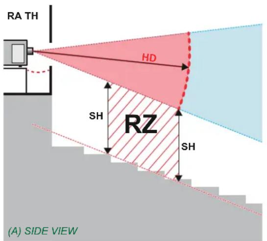
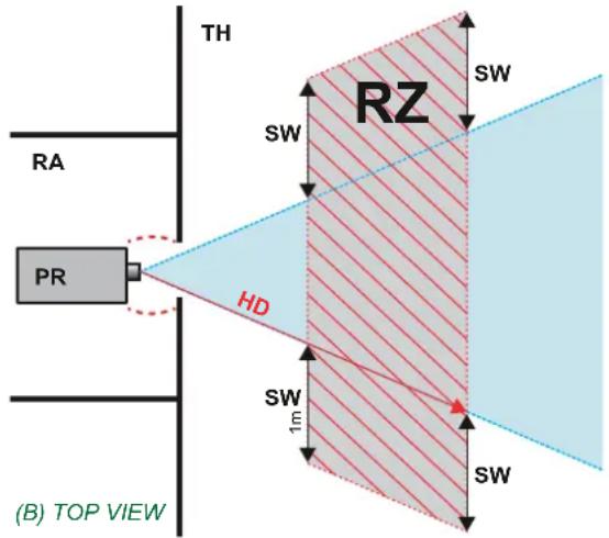
Image 1-1
A Side view.
B. Top view
RA Restricted Access location (boot area of projector).
PR Projector.
TH Theater.
RZ Restriction Zone in the theater.
SH Separation Height
SW Separation Width.
Based on national requirements, no person is allowed to enter the projected beam within the zone between the projection lens and the related hazard distance (HD). This shall be physically impossible by creating sufficient separation height or by placing barriers. The minimum separation height takes into account the surface upon which persons other than operator, performers or employees are permitted to stand.
On image 1-2 a typical setup is displayed. It must be verified if these minimum requirements are met. If required a restricted zone (RZ) in the theater must be established. This can be done by using physical barrier, like a red rope as illustrated in image 1-2.
The restricted area sticker can be replaced by a sticker with only the symbol.
1. Safety
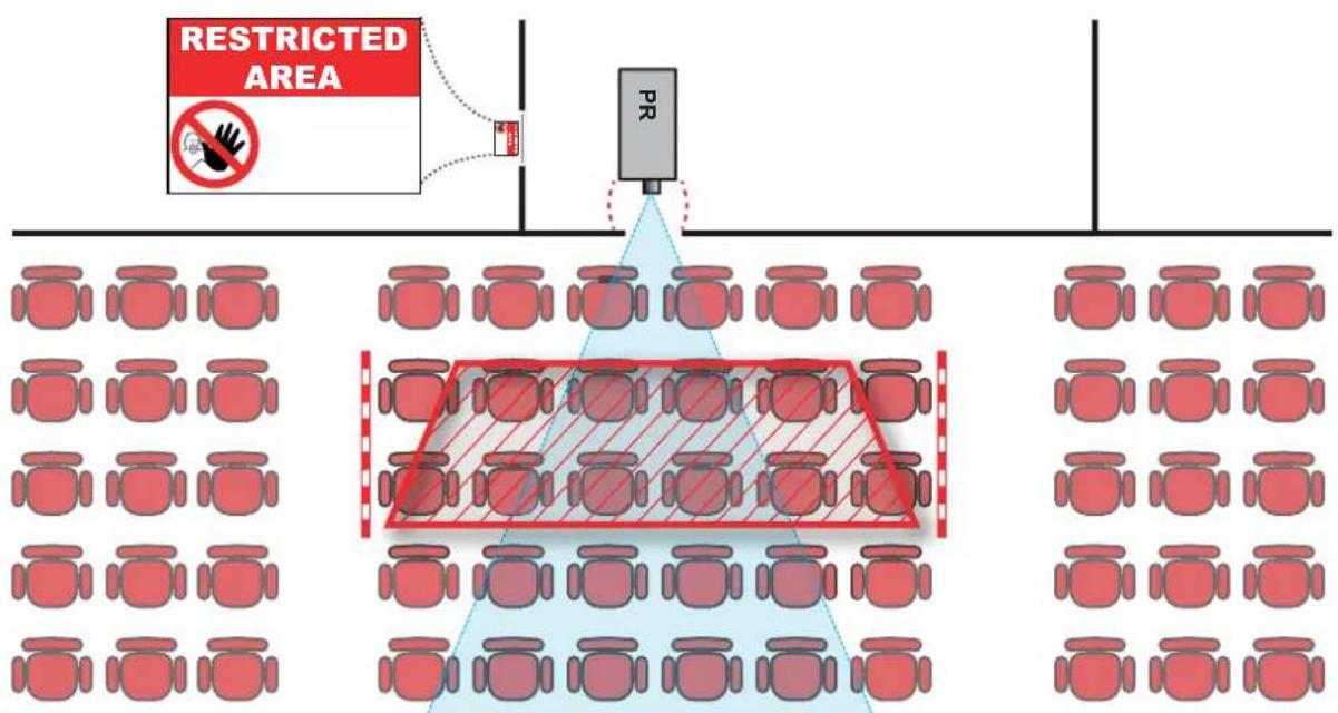
Image 1-2
1.4HDforfullyenclosedprojectionsystems

HD
Hazard Distance (HD) is the distance measured from the projection lens at which the intensity or the energy per surface unit becomes lower than the applicable exposure limit on the cornea or on the skin. The light beam is considered (to be) unsafe for exposure if the distance from a person to the light source is less than the HD.
RestrictionZone(RZ)basedontheHD
The projector is also suitable for rear projection applications; projecting a beam onto a defuse coated projection screen. As displayed in image 1-3 two areas should be considered: the restricted enclosed projection area (RA) and the observation area (TH).
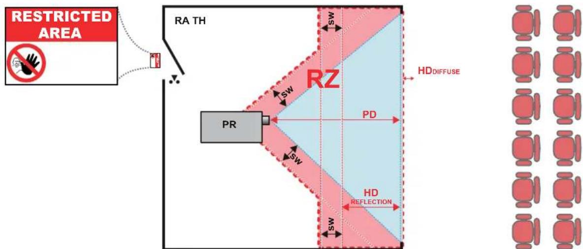
Image 1-3
RA Restricted Access location (enclosed projection area).
PR Projector.
TH Theater (observation area).
RZ Restriction Zone.
PD Projection Distance.
SW Separation Widt h. Must be minimum 1 meter.
For this type of setup 3 different HD shall be considered:
• HD as discussed in "High Brightness precautions: Hazard Distance (HD)", page 7, relevant for intrabeam exposure.
- HD reflection : the distance that has to be kept restrictive related to the reflected light from the rear projection screen.
- HD diffuse : the relevant distance to be considered while observing the defuse surface of the rear projection screen.
As described in "High Brightness precautions: Hazard Distance (HD)", page 7, it is mandatory to create a restricted zone within the beam areas closer than any NOHD. In the enclosed projection area the combination of two restricted zones are relevant: The restricted zone of the projected beam toward the screen; taking into account 1 meter Separation Width (SW) from the beam onward. Combined with the restricted zone related to the rear reflection from the screen ( HD_reflection ); also taking into account a 1 meter lateral separation.
The HD reflection distance equals 25% of the difference between the determined HD distance and the projection distance to the rear projection screen. To determine the HD distance for the used lens and projector model see graphs in chapter "HD in function of the lens Throw Ratio (TR)", page 9.
$$ \mathrm{HD} _ {\text { reflection }} = 25 \% (\mathrm{HD} - \mathrm{PD}) $$
The light emitted from the screen within the observation shall never exceed the RG2 exposure limit, determined at 10 cm. The HD diffuse can be neglected if the measured light at the screen surface is below 5000 cd/m² or 15000 LUX.
1.5HDinfunctionofthelensThrowRatio(TR)

TR(ThrowRatio)
The ratio of the distance to the screen (throw) to the screen width.
HDXseriesprojectorHazardDistance
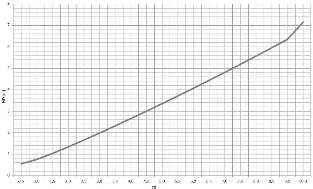
line
| TR | HD (m) | | ---- | ------ | | 0.5 | 0.5 | | 1.0 | 0.8 | | 1.5 | 1.2 | | 2.0 | 1.6 | | 2.5 | 2.0 | | 3.0 | 2.4 | | 3.5 | 2.8 | | 4.0 | 3.2 | | 4.5 | 3.6 | | 5.0 | 4.0 | | 5.5 | 4.4 | | 6.0 | 4.8 | | 6.5 | 5.2 | | 7.0 | 5.6 | | 7.5 | 6.0 | | 8.0 | 6.4 | | 8.5 | 6.8 | | 9.0 | 7.2 | | 9.5 | 7.6 | | 10.0 | 8.0 |Image 1-4 HD (in meter) in function of the Throw Ratio (TR)
1.6 Important warnings concerning HDXflight cases
Important warnings concerning stacking/transporting HDX rental flight cases
• Stack maximum two (2) HDX rental flight cases high. Never higher.
- Surface on which flight case is standing must be level to ensure that the total load is evenly spread out among the four wheels. The surface must also be able to support the load safely.
• Before stacking or transporting flight cases, check the wheels and their fixation screws for wear or defects.
- Before stacking or transporting flight cases, check that the four lock handles on each flight case are in good working order and locked securely.
- When stacked, make sure the wheels of the upper flight case are precisely positioned in the stacking dishes of the flight case below.
- Stacked flight cases may not be moved. Before stacking, the lower flight case must already be in its final resting position before placing the second upon it.
• Never stack loaded flight cases in a truck or other transport medium, unless each flight case is rigidly strapped tight.
• In the event of a wheel breaking, flight cases must be rigidly strapped tight to prevent a stack collapsing.
• Use an appropriate forklift to raise flight cases and take the necessary precautions to avoid personnel injury.
2.INSTALLATIONPREPARATIONS
Aboutthischapter
Read this chapter before installing the HDX projector. It contains important information concerning installation requirements for the projector, such as minimum and maximum allowed ambient temperature, humidity conditions, required safety area around the installed projector, required power net, etc.
Furthermore, careful consideration of things such as image size, ambient light level, projector placement and type of screen to use are critical to the optimum use of the projection system.

Barcoprovidesaguaranteerelatingtoperfectmanufacturingaspartofthelegallystipulatedtermsofguarantee. Observing the specification mentioned in this chapter is critical for projector performance. Neglecting thiscanresultinlossofwarranty.
Overview
• Installation requirements
- Unpacking the projector
- Initial inspection
- HDX flight case
- Projector configurations
- Projector air inlets and outlets
• Free download of Projector Toolset
2.1 Installationrequirements
Environmentconditions
Table below summarizes the physical environment in which the HDX may be safely operated or stored.
EnvironmentOperatingNon-Operating
| Ambient Temperature | 10 °C (50 °F) to 40 °C (104 °F) | -15°C (5°F) to 60°C (140°F) |
| Humidity | 5% to 85% RH Non-condensed | 5% to 95% RH Non-Condensed |
| Altitude | -60 (-197Ft) to 3000m (9843Ft) | -60 (-197Ft) to 10000m (32810Ft) |

Let the projector acclimatize after unpacking. Neglecting this may result in a startup failure of the Light ProcessorUnit.
Coolingrequirements
The projector is fan cooled and must be installed with sufficient space around the projector head, minimum 10 cm (4 inch) to ensure sufficient air flow. It should be used in an area where the ambient temperature, as measured at the projector air inlet, does not exceed +40°C (+104°F).
Cleanairenvironment
A projector must always be mounted in a manner which ensures the free flow of clean air into the projectors ventilation inlets. For installations in environments where the projector is subject to airborne contaminants such as that produced by smoke machines or similar (these deposit a thin layer of greasy residue upon the projectors internal optics and imaging electronic surfaces, degrading performance), then it is highly advisable and desirable to have this contamination removed prior to it reaching the projectors clean air supply. Devices or structures to extract or shield contaminated air well away from the projector are a prerequisite, if this is not a feasible solution then measures to relocate the projector to a clean air environment should be considered.
Only ever use the manufacturer's recommended cleaning kit which has been specifically designed for cleaning optical parts, never use industrial strength cleaners on the projector's optics as these will degrade optical coatings and damage sensitive optoelectronics components. Failure to take suitable precautions to protect the projector from the effects of persistent and prolonged air contaminants will culminate in extensive and irreversible ingrained optical damage. At this stage cleaning of the internal optical units will be noneffective and impracticable. Damage of this nature is under no circumstances covered under the manufacturer's warranty and may deem the warranty null and void. In such a case the client shall be held solely responsible for all costs incurred during any repair. It is the clients responsibility to ensure at all times that the projector is protected from the harmful effects of hostile airborne particles in the environment of the projector. The manufacturer reserves the right to refuse repair if a projector has been subject to knowingly neglect, abandon or improper use.
MainPowerrequirements
The HDX operates from a nominal mono phase power net with a separate earth ground PE.
Power requirements : 110-130V/200-240 V, 15A, 50-60Hz
The power cord required to connect the projector with the power net is delivered with the projector.
Projectorweight
Do not underestimate the weight of the HDX. The projector weights about ±50 kg ( ±111 lb.) without lens. Be sure that the pedestal on which the projector has to be installed is capable of handling five (5) times the complete load of the system.
2.2 Unpacking the projector
Whathastobedone?
Upon delivery, the projector is packed in a carton box upon a wooden pallet and secured with banding and fastening clips. Furthermore, to provide protection during transportation, the projector is surrounded with foam. Once the projector has arrived at the installation site, it needs to be removed from the carton box and wooden pallet in a safe manner without damaging the projector.

After unpacking let the projector acclimatize to a room temperature higher then 10^ C ( 50^ F) and lower then 40^ C ( 104^ F). Neglecting this may result in a start up failure of the Light Processor Unit.
Necessarytools
cutter knife
Howtounpack
- Remove the banding around the carton box, by releasing the fastening clips as illustrated, and open the box.
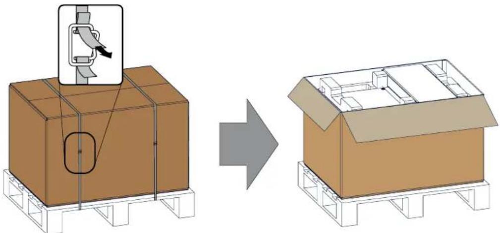
natural_image
Diagram showing a mechanical assembly on a box before and after transformation, with no visible text or symbols.Image 2-1 Opening box
- Remove the small box on top of the projector. This box contains the accessories such as manuals, remote control, etc.
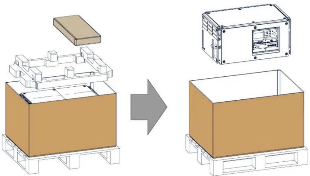
natural_image
Diagram showing a device assembly process: top-down view of a box with a lid, side view of a control panel, and final assembled view (no text or symbols)Image 2-2 Remove carton and foam rubber
- Take out the foam rubber.
- Take out the projector.

Save the original shipping carton and packing material, they will be necessary if you ever have to ship your projector. For maximum protection, repack your projector as it was originally packed at the factory.

A rubber foam inside a plastic bag is placed into the lens opening of the projector. It's recommended to reuse this foam and plastic back each time you transport the projector. This to prevent intrusion of dust and foreign particles.

Thelensisdeliveredinaseparatebox.
2.3 Initial inspection
General
Before shipment, the projector was inspected and found to be free of mechanical and electrical defects. As soon as the projector is unpacked, inspect for any damage that may have occurred in transit. Save all packing material until the inspection is completed. If damage is found, file claim with carrier immediately. The Barco Sales and Service office should be notified as soon as possible.

The packaging of the HDX is provided with a shock-watch label. If this shock-watch label was triggered (red colored at arrival) during transport, that indicates that the package was possibly roughly handled by the transport company. In this case, the instructions mentioned on the label, should be followed, which are: adding a note on the "bill of lading" and informing the transport company and the Barco sales and service office as soonaspossible.
Boxcontent
After unpacking the projector it is recommended to check if all following items where included:
• Three power cords of 2.5 meter, one CEE (7), one NEMA L6-20P and one CH2-16P
• One Quick Start guide
• One Safety manual
• One Web site reference sheet
• One remote control unit (RCU)
• 2 batteries for the RCU.

Onexenonlampismountedinsidethelamphouseatdelivery.Theprojectorlensesarenotincludedinthe packageoftheprojector.
Mechanicalcheck
This check should confirm that there are no broken knobs or connectors, that the cabinet and panel surfaces are free of dents and scratches, and that the operating panel is not scratched or cracked. The Barco Sales and Service office should be notified as soon as possible if this is not the case.
2.4HDXflightcase
IntroductionoftheHDXflightcase
The HDX flight case is designed to transport the HDX in a safe and secure manner. The four caster wheels, provided with breaks, and the four handles make the HDX flight case easy to handle. The floor of the flight case wagon is equipped with two small covered compartments to store the remote control and the rigging clamps.
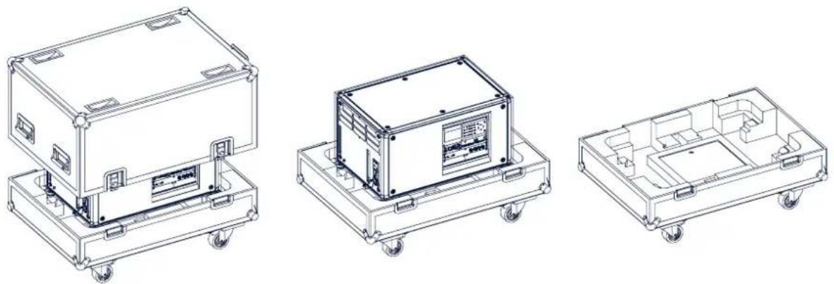
natural_image
Three technical line drawings of a mechanical device chassis with wheels, showing front, top, and side views (no text or symbols present)Image 2-3
HDX Flight case
Order number flight case: R9864090
The dimensions of the flight case are optimal for maximum utilization of the floor area of a truck. The cover of the HDX flight case has 4 stacking dishes, which allows to stack the flight cases.

WARNING: Maximum stack two (2) HDX flight cases high. Never higher.
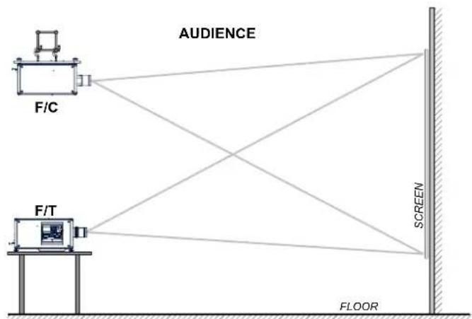
2.5Projectorconfigurations
Thedifferentconfigurations
Depending on the installation the projector can be mounted in different ways, the different configurations are:
- Front / Table (F/T)
- Front / Ceiling (F/C) (upside down)
- Front / Ceiling (F/C) (table position)
- Rear / Table (R/T)
- Rear / Ceiling (R/C) (upside down)
- Rear / Ceiling (R/C) (table position)
Frontprojection
The projector is installed, either in a table mount or ceiling mount configuration, at the same side of the screen as the audience.
flowchart
graph TD
    A["FA/C"] --> B["AUDIENCE"]
    C["F/T"] --> B
    B --> D["SCREEN"]
    D --> E["FLOOR"]
Image 2-4 Front projection
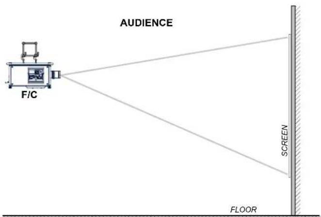
Image 2-5 Front projection, Ceiling mounted, in table position
Rearprojection
The projector is installed, either in a table mount or ceiling mount configuration, at the other side of the screen opposite the audience.
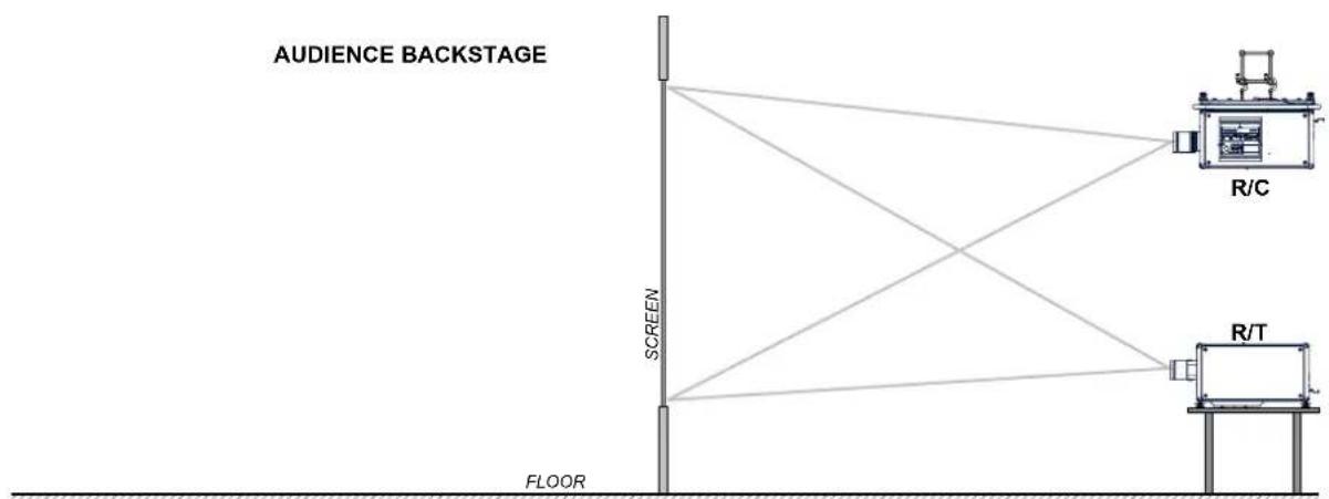
Image 2-6 Rear projection
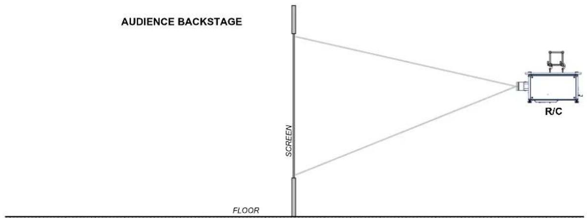
Image 2-7 Rear projection, ceiling mounted in table position
Positioning the projector
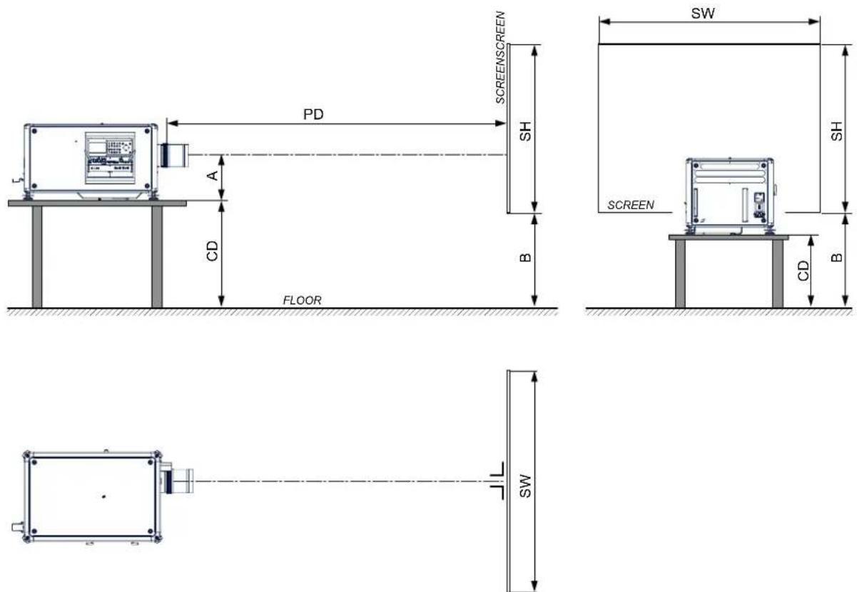
Image 2-8 Positioning projector
The projector should be installed at right angles (horizontally and vertically) to the screen at a distance PD. Note the distance (A) between lens centre and table surface is slightly variable. This distance (A) is nominal 35 cm in case all feet are turned in completely and the vertical lens shift is set to zero (0).
Onaxis/offaxisprojection
The position of the projector with reference to the screen may also be different depending on the installation. Basically the projector can be positioned in On-Axis or Off-Axis configuration. On-Axis configuration means that the projector is positioned so as to have the centre of the lens coinciding with the centre of the screen. Off-Axis projection is obtained by shifting the lens up, down, left or right. Several parameters can be calculated determining the position in any installation.
Formula to calculate the distance CD for On-Axis projection: CD = SH/2 + B - A
Shiftrange
The lens can be shifted with respect to the DMD (P) which result in a shifted image on the screen (Off-Axis). A 100% shift means that the centre point of the projected image is shifted by half the screen size. In other words, the centre point of the projected image falls together with the outline of the image in an On-Axis projection. Due to mechanical and optical limitations it's recommended to keep the shift values within the field of view (F) as illustrated below. Within these shift ranges the projector and lens perform excellently. Configuring the projector outside these shift ranges will result in a slight decline of image quality.
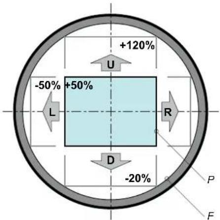
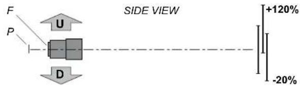
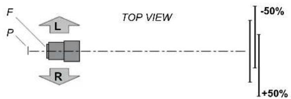
Image 2-9
Vertical and horizontal shift range
P D M D
F Field of view.

It is mechanical possible to shift outside the recommended field of view, but it will result in a decline of image quality depending on the used lens and the zoom position of the used lens. Furthermore, shifting too much in both directions will result in ablurred image corner.

BestimagequalityisprojectedintheOn-Axisconfiguration.
Horizontalandverticalprojectortiltranges
The projector can be rotated and mounted at any vertical angle. In other words, you can tilt the lens side of the projector as much as desired for your application.
Side to side tilt, however, must not exceed ± 15^ . This limit ensures that the lamp in the projector operates properly and safely. More tilting within area C is allowed but lamp flicker can happen.
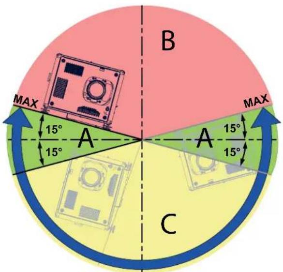
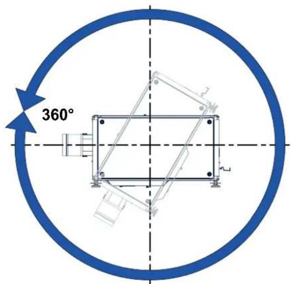
Image 2-10
A Tilting allowed without problems
B No tilting allowed in this area
C Tilting allowed but lamp flicker possible

Projectorlampwillnotstartupwhenoutoftiltrangeduetobuild-intiltsensor.
2.6Projectorairinletsandoutlets
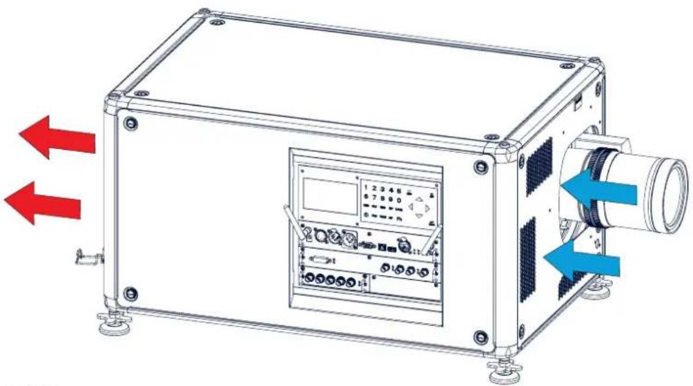
Airinletsandoutlets
natural_image
Technical line drawing of a mechanical device with two red arrows pointing to the left side (no text or symbols on the device itself)Image 2-11
The HDX has 3 air inlet channels and 3 air outlets. The air outlets are located at the rear of the projector. The air inlets are located at the front of the projector.
2.7FreedownloadofProjectorToolset
AboutProjectorToolset
Projector Toolset is a software tool to set up, configure, manage and control Barco projectors.
The concept of this Projector Toolset software is modular. The basic package can be extended with several optional device plug-in modules, now and in the future available.
The Projector Toolset software works with configurations that can be loaded. Within a configuration, different snapshots can be taken. A snapshot represents a current state of a configuration and can be reloaded to return to this typical state. These terms will be used through the complete software.
Projector Toolset is a stand-alone application that runs on a Java Virtual Machine and that does not require extra services to run.
Several configurations can be controlled simultaneously. Even when the configurations are connected via different ways.

ProjectorToolsetisonlyavaila bleinadownloadversion,noCDcanbeordered.
Where to find the download file(s)
The program and all necessary plug-ins, as well as the Reference manual can be downloaded for free from my.barco.com. Registration is necessary.
-
Go to the Barco website www.barco.com.
-
On the home page, click on myBarcologin.
-
On the Sign In page, enter your Email address and your password to login. If you are not yet registered click on New to myBarco? and follow the instructions. With the created login and password, it is possible to enter the Partnerzone of Barco. When your login is correct, the Partnerzone is free accessible.
-
In the search field, enter Projector Toolset and click on the search icon.
-
Select Technical Downloads.
-
Click on Application Software and download the Projector Toolset software package, which includes the device plug-in updates.
When downloading the complete Projector Toolset, this software contains already the latest device plug-ins. When you already have the latest core version of Projector Toolset, it is possible to download only device plug-in updates from the same web site location.
As Projector Toolset is a stand alone application, it is not necessary to install any other software. A Java virtual machine is included with this download.
To download the reference manual, select Reference Guide and download the latest version of the manual for your projector.
Installation
Download first the reference manual and follow the installation instructions as written in this manual.
3.PHYSICALINSTALLATION
Overview
- Connecting the projector with the power net
- Alignment of a table mounted projector
- Mounting the bottom carry handler
- Mounting the top carry handler
- Suspension of the projector with rigging clamps
- Alignment of a ceiling mounted projector
3.1 Connecting the projector with the powernet

CAUTION: Use only the power cord provided with the projector.
Howtoconnectwithlocalpowernet
- Ensure that the power switch stands in the '0' (OFF) position (1).
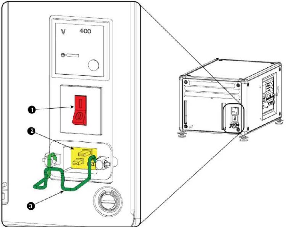
Image 3-1 Power input
- Connect the female side of the power cord with the power input socket of the projector (2).
- Secure the power plug by locking the plug holder clamp (3).
- Connect the male side of the power cord to the local power net.
Caution: Ensure that the powernet meets the power requirement so the projector.

WARNING: Do not attempt operation if the AC supply and cord are not within the specified voltage and power range.

CAUTION: Once the projector is switched to standby, the lamp cooling fans will continue to run for approximately five minutes to ensure that the projector and lamp have sufficiently cooled, at which point the fans will automatically decrease to standby. To avoid thermal stress that can lead to premature lamp failure, never unplug the power cord while the lamp cooling fans are running. Never unplug the power cord topower down the projector, first switch off the power switch and then unplug the power cord.
Fuses
The projector is protected with an automatic circuit breaker of 20 A which is built into the power switch.
The voltage meter is protected with a fuse (1A) which is located on the neutral bonding cable. If necessary to replace this fuse, consult a service technician.
3.2 Alignmentofatablemountedprojector
Howtoalign
- Place the projector in the desired location. Take into account the zoom range of the used lens and the size of the screen.
- Project one of the internal hatch patterns on the screen.
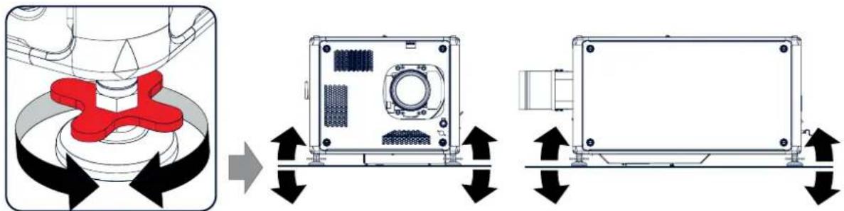
- Turn the adjustable feet in or out until the projected hatch pattern has a perfect rectangle shape and is leveled.
natural_image
Diagram showing mechanical assembly with red component and two views of a device (no text or symbols)Image 3-2 Level alignment
When this is achieved, the projector is set horizontal and vertical at right angles to the screen.
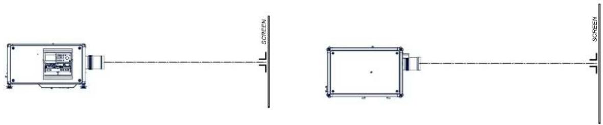
Image 3-3 Angle adjustment
3.3Mountingthebottomcarryhandler
Necessarytools
Open wrench 17 mm
Necessaryparts
4x bolt M10 x 16 mm
Howtomount
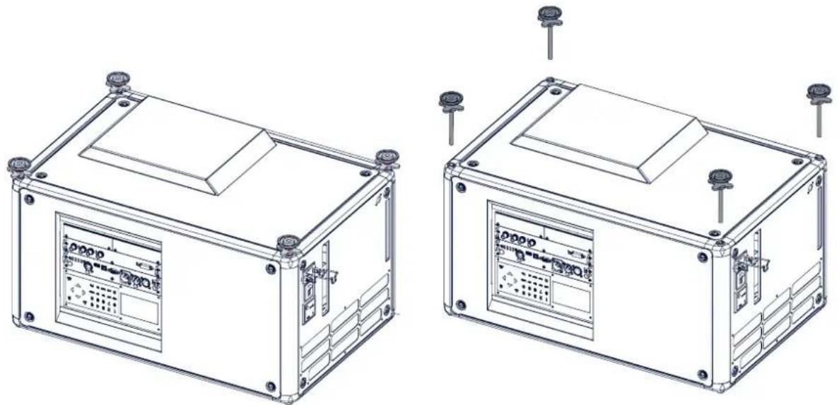
- Turn the projector upside down.
- Turn out the 4 feet.
natural_image
Technical line drawings of two electronic device modules with mounting hardware (no text or symbols)Image 3-4 Remove feet
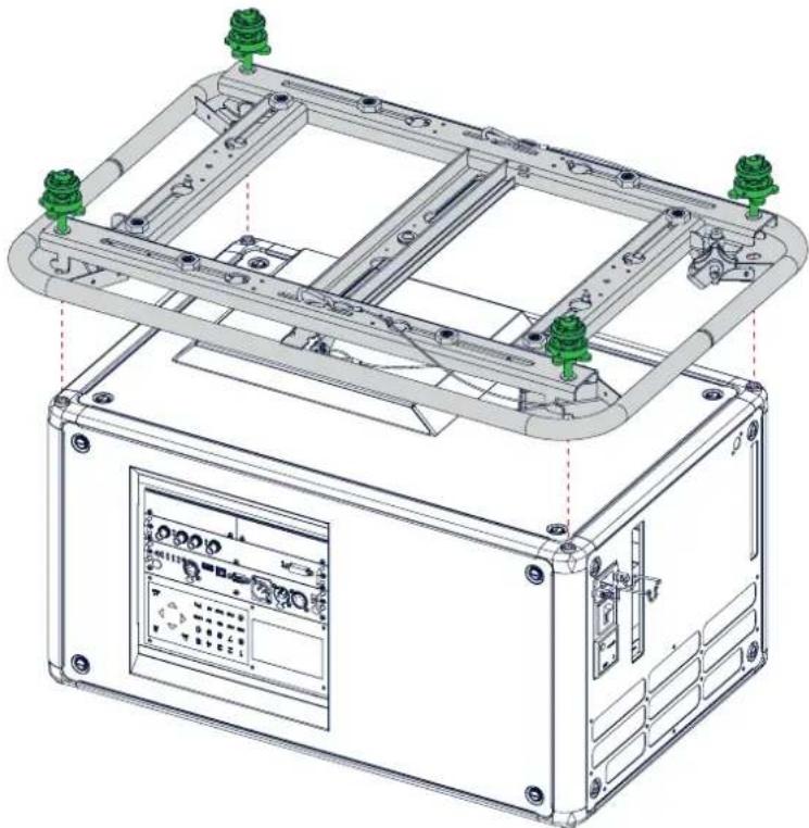
- Turn out the feet of the carry handle as far as possible.
natural_image
Technical line drawing of a mechanical assembly with green connectors and mounting brackets (no text or symbols)Image 3-5 Mount carry handle
- Place the carry handle on the projector as illustrated. Adjustment knob to the back of the projector. Make sure that the mounting holes matches the holes in the projector.
- Insert a bolt in each corner and turn in these bolts.
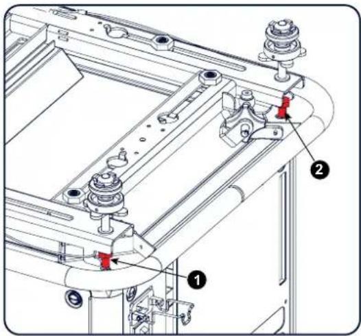
Image 3-6 Insert bolts
3.4Mountingthetopcarryhandler
Purpose
This carry handle can be used to transport the projector in an easy way.
Necessarytools
8 mm Allen wrench
Necessaryparts
- 4x bolt M10 x 16
- 4x washer
- 1x carry handler
Howtomount
- Place the carry handle on top of the projector so that the fixation holes match the holes in the projector.
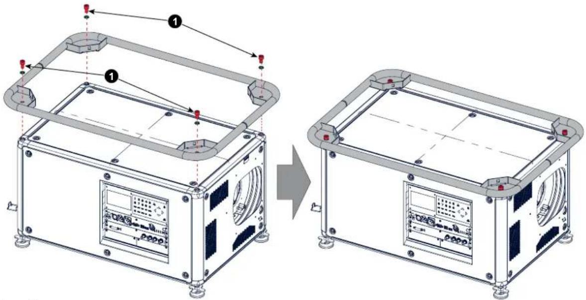
Image 3-7 top carry handle
- Turn in the 4 fixation bolts (1). Insert a washer between the bolt and the carry handle.
3.5 Suspension of the projector with rigging clamps
Riggingpointsandriggingclamps
When a carrying handle is mounted at the bottom side of the projector, eight slots are available to mount rigging clamps. Four slots are longitudinally (1) oriented and four slots are transversely (2) oriented. Each slot contains a rigging point of which the position in the slot can be adjusted depending on the size of the truss installation. The rigging clamps can be attached to those rigging points, which allows an easy and fast physical setup of the projector in a hanging configuration.
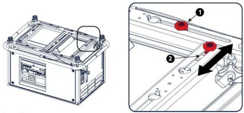
Image 3-8 Rigging points
Necessarytools
- Open end spanner 24 mm
- Open end spanner 17 mm
Necessaryparts
4 rigging clamps
Howtoinstallandusetheriggingclamps
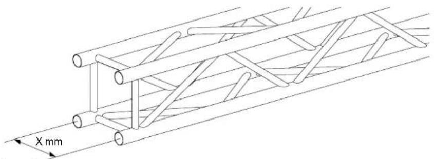
- Measure the distance, center tube as reference, between the two used support bars of the truss.
natural_image
Technical line drawing of a mechanical truss structure with X mm dimension标注 (no text or symbols beyond measurement)Image 3-9 Truss, example
- Turn the projector upside down and slide the rigging points on there place in the slots, according the measured distance and secure this position. To release the nuts of the rigging points use a 24 mm open ended spanner. Ensure that the rigging points are symmetrically lined up, so that the projector will hang in balance. Warning: Becarefulwhileworkingwithheavyloads.
Warning: Always secure the rigging points after adjustment.
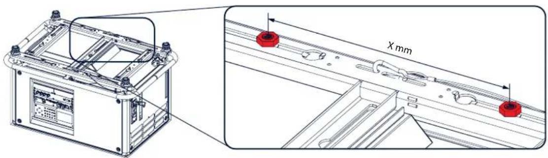
Image 3-10 Rigging points, distance
3. Physical Installation
- Turn in the rigging clamps into the rigging points using a 17 mm open ended spanner and secure the rigging clamps by turning the safety nut on the rigging clamp against the rigging point using a 17 mm open ended spanner.
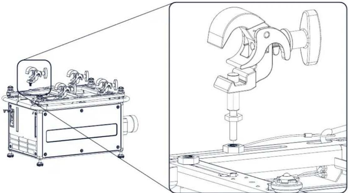
natural_image
Technical line drawing of a mechanical device with mounting bracket and internal components, shown from two orthographic views (no text or symbols present)Image 3-11
Mount rigging clamps
Warning: Alwaysusefour(4)riggingpoints, equallyspread, to suspend the projector.
- Place all four rigging clamps in open position.
- Place the projector (upside down) under the truss installation and lower the truss until the support bars of the truss are nearby the rigging clamps mounted on the projector.
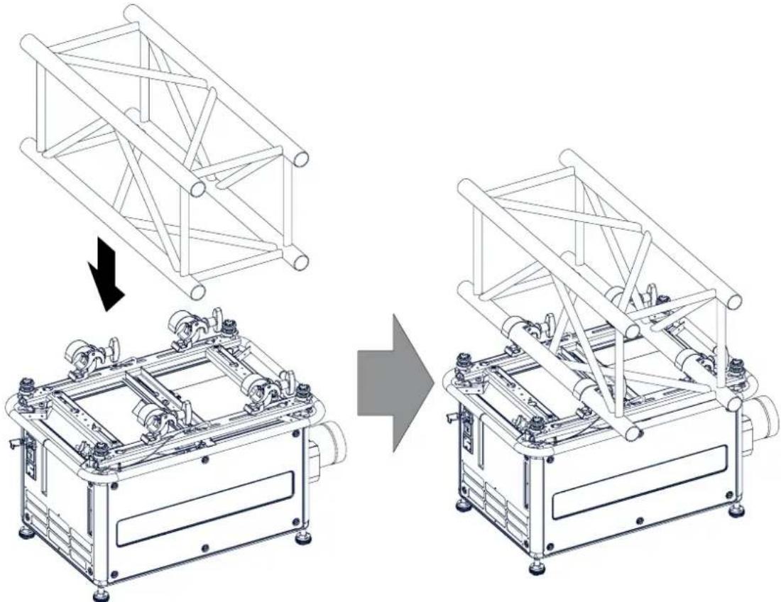
natural_image
Technical line drawing of a mechanical assembly showing structural transformation from a frame structure to a motor or platform device (no text or symbols present)Image 3-12
Mount to truss
-
Lift up the projector and hook the four rigging clamps over the support bars of the truss.
-
Lock all four rigging clamps by turning the fixation handle clockwise.
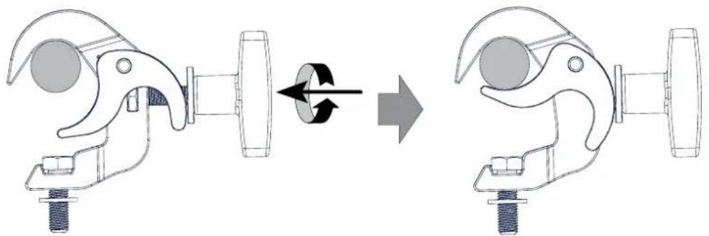
natural_image
Diagram showing a mechanical clamp mechanism before and after rotation, with no text or symbols present.Image 3-13 Clamp fixation
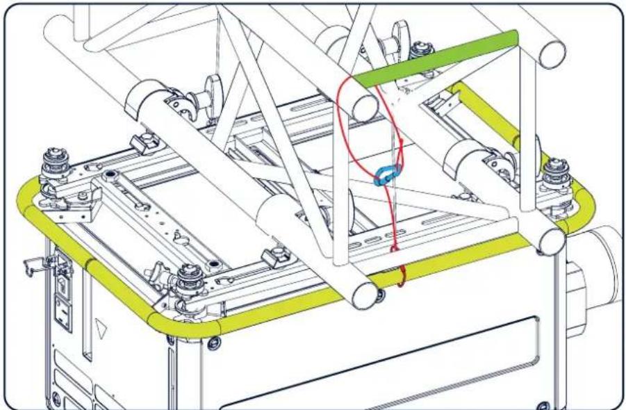
- Install the 2 safety cables, one on both sides of the carrying handle, and around the truss. Mount the 2 safety cables around the carry handle (push the hook through the loop and then around the truss so that there is not to much play (maximum 20 cm). If necessary turn the cable a few times around the truss before clasping the safety hook around the cable.
natural_image
Technical line drawing of a mechanical assembly with no visible text or symbolsImage 3-14 Security cables
- Lift up the truss with the attached projector to the desired height.

Mountthe2safetycablesinsuchawaythatwhensomethinggoeswrong,theprojectorcannotfallmorethan 20 cm. If necessary, turn the cables a few times around the truss to obtain this maximum distance.
3.6 Alignment of faceiling mounted projector
Necessarytools
17 mm open spanner
Skewadjustment
- Turn the adjustment knob on the carry handle until the projected hatch pattern is perfectly squared.
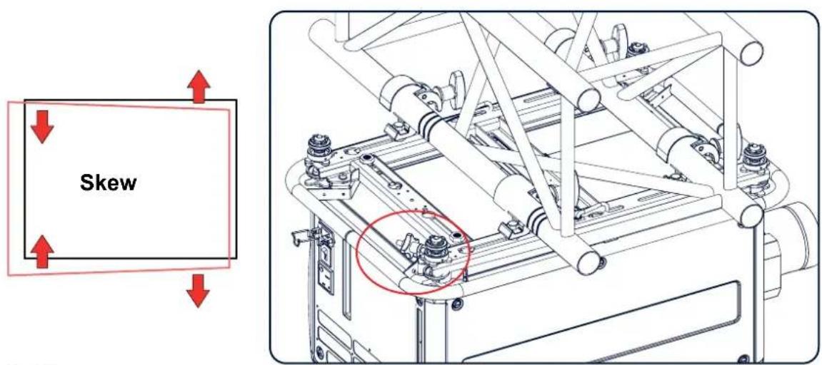
Image 3-15
Skew adjustment
Tiltadjustmentwiththeclamps
- Adjust both front side clamp or both back side clamps to adjust the tilting.
Always adjust by two to avoid deformation of the frame. - Loosen the security nut on both clamps.
- Adjust the adjustment nuts of both clamps until the desired tilting is reached.
- Turn the safety nut on the rigging clamp against the rigging point
4.LENSSES&LENSSELECTION
Overview
• Available lenses
- Lens selection
- Lens installation
- Lens removal
- Lens safety cable
- Scheimpflug adjustment
4.1 Availablelenses

WARNING: Only use TLD+ ZOOM lenses. Using other lenses can touch and damage the mechanics of the build-in actuator! This can result in loud rattling noises and a damaged actuator.
Limitedamountofavailablelenses
In comparison to the regular HDX, the HDX 4k projectors have an actuator built in them to help provide a clear 4k image. This extra device means that less space is available in the projector for lenses, thus causing a more restricted amount of lenses that can be used. Using lenses other than the lenses mentioned in this chapter may damage the mechanics of the actuator, causing loud rattling noises in the process and possibly a distorted image.
Due to the similar look to the "regular" 2k HDX projector, an extra warning label has been added on the lens holder to raise awareness of this limit.

Image 4-1 Warning label
AvailablelensesfortheHDXprojector
Only the following TLD+ ZOOM Lenses can be used on the HDX projector. Do not use other types of lenses.
natural_image
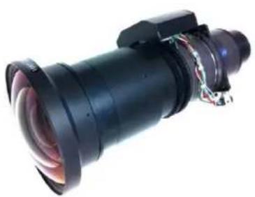
Close-up of a black cylindrical optical lens with visible internal components and wiring (no text or symbols)Image 4-2 R9801414: TLD+ zoom lens (0.8 - 1.16 : 1)
natural_image
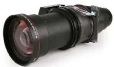
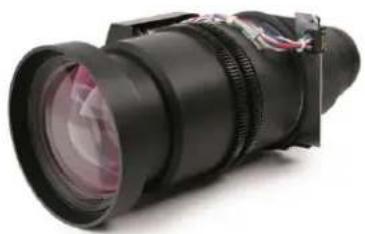
Close-up of a black professional lens with adjustable eyewear and cable (no visible text or symbols)Image 4-3 R9862005: TLD+ zoom lens (1.16 - 1.49 : 1)
natural_image
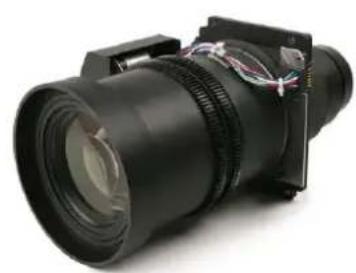
Close-up of a black professional lens with visible focal lines and lenses (no text or symbols)Image 4-4 R9862010: TLD+ zoom lens (1.5 - 2.0 : 1)
natural_image
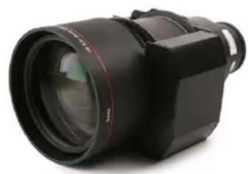
Close-up of a black optical lens with visible wiring and lens components (no text or symbols)Image 4-5 R9862020: TLD+ zoom lens (2.0 - 2.8 : 1)
natural_image
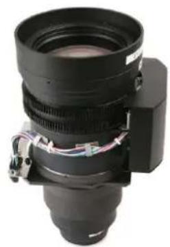
Close-up of a black professional lens with adjustable eyewear (no visible text or symbols)Image 4-6 R9862030: TLD+ zoom lens (2.8 - 4.5 : 1)
natural_image
Close-up of a black camera lens with visible internal components and wiring (no text or symbols)Image 4-7 R9862040: TLD+ zoom lens (4.5 - 7.5 : 1)
natural_image
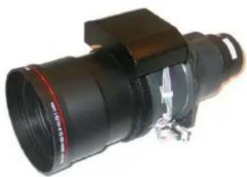
Close-up of a black camera lens with attached bracket and metallic clip (no visible text or symbols)Image 4-8 R9829997: TLD+ zoom lens (7.5 - 11.0 : 1)
4.2 Lensselection
Howtoselecttherightlens
- Determine the required screen width (SW).
- Determine the approximate position of the projector in the room.
- Start up the Lens Calculator on the Barco website: https://www.barco.com/en/media_entertainment/LensCalculator to determine the possible lenses for your configuration.
The Lens Calculator window opens.
![Barco.com | Lens Calculator CLM HD6 Resolution: 1920x1080 px Light output: 4000 lenses CLM HD8 Resolution: 1920x1080 px Light output: 4000 lenses CLM R10+ Resolution: 2400x4050 px Light output: 35000 lenses ELM G10 Resolution: 3420x769 px Light output: 35000 lenses ELM R12 Resolution: 1280x1024 px Light output: 12500 lenses ELM R12 Director Resolution: 1280x1024 px Light output: 12500 lenses ELM R18 Director Resolution: 1280x1024 px Light output: 12500 lenses FLM HD14 Resolution: 1920x1080 px Light output: 54000 lenses FLM HD18 Resolution: 1920x1080 px Light output: 55000 lenses FLM HD20 Resolution: 1920x1080 px Light output: 26000 lenses Lens calculator Blend calculator [reset] Screen ratio 16:9 16:10 4:3 5:4 26:48:1080 Free Screen width m Screen height m Screen aperture m Projector distance m Ambient light Lux Screen gain % Lamp lift % Stack projectors F Horizontal shift % Vertical shift % Vertical shift Throw ratio CWR 0.81 +10% to 10% -10% to 10% CWR 1.37-1.82 -30% to 30% -80% to 100% CWR 3.33-3.93 -50% to 35% -80% to 100% ✓CWR 3.63-3.85 -30% to 35% -85% to 125% CWR 3.83-3.33 -30% to 35% -85% to 125% Available lenses for CLM HD6 Lens Horizontal shift Vertical shift Throw ratio 4.931 207-462 26-333 26-463 26-533 26-633 26-733 Contrast on screen: 146.7.1 Lux on screen: 666.5 Quelay diffus](/content/2026/05/975568/images/7fdcb74be2316b5123320d513b82c8ce5ad1c9473ec1f57a42bf7d1653dd763e.jpg)
Image 4-9 Lens calculator

The Lens Calculator can also be used to determine the position of the projector when the lens type and screen width is known.

Due to lens tolerances the results of calculated values may be different from measured values. These differ-encemayvary+/-5%.
4.3 Lens installation

WARNING: Only use TLD+ ZOOM lenses. Using other lenses can touch and damage the mechanics of the build-in actuator! This can result in loud rattling noises and a damaged actuator.
Howtoinstall
- Remove the foam rubber in the opening of the lens holder if not removed yet.
- Do not remove the warning sticker from the lens holder.
- Take the lens assembly out of its packing material and remove the lens caps on both sides.
- Place the lens holder in the "unlocked" position by moving the lens lock handle (A) towards the lens power supply socket (B) as illustrated.
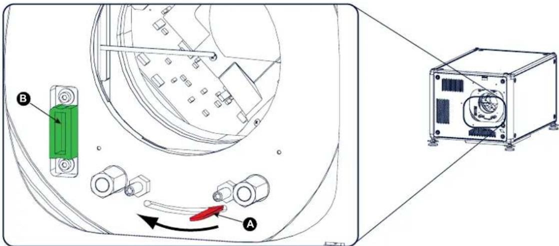
Image 4-10
Lens installation, preparation
- Ensure that the lens holder stands in the On-Axis position (horizontal and vertical mid position).
Note: The lens holder is placed default in the On-Axis position at factory.
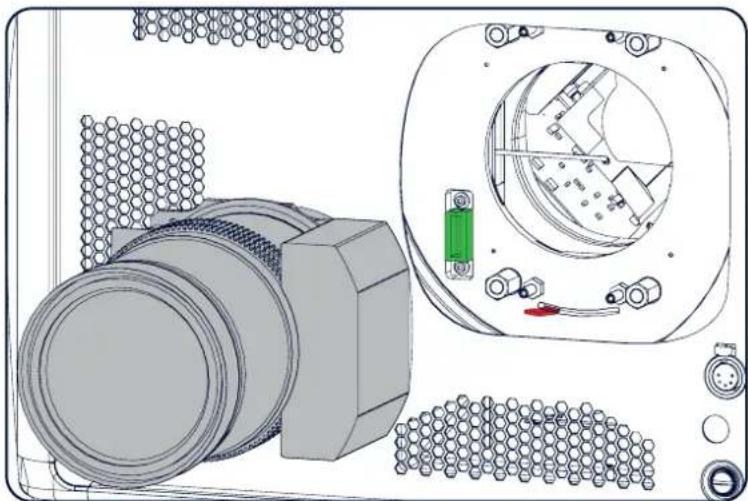
- Gently insert the lens in such a way that the lens connector matches the socket (B).
natural_image
Technical diagram of a mechanical assembly with components and housing (no visible text or symbols)Image 4-11
Lens insertion
- Insert the lens until the connector seats into the socket.
Warning: Do not release the Lens yet, as the Lens may fall out of the Lens Holder.
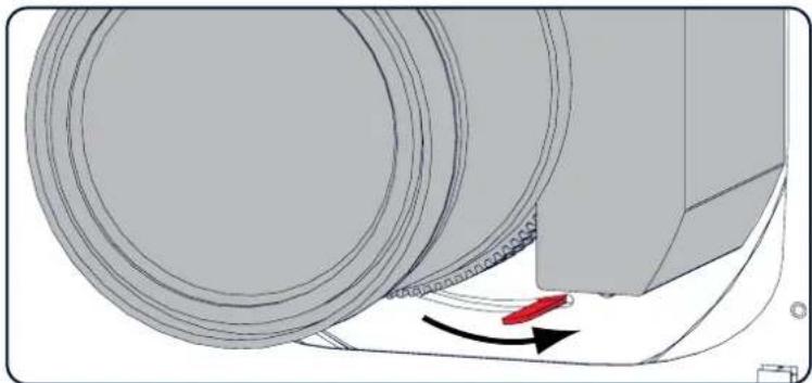
- Secure the lens in the lens holder by sliding the lens lock handle into the "locked" position, which is away from the lens power supply socket. Ensure the lens touches the front plate of the lens holder.
natural_image
Mechanical assembly diagram showing a rotating component with red directional arrow (no text or symbols)Image 4-12
Lock lens
- Check if the lens is really secured by trying to pull the lens out of the lens holder.
4.4 Lensremoval
Howtoremove
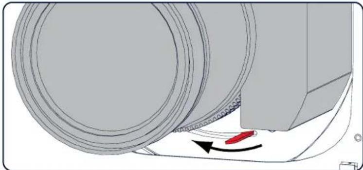
- Support the lens with one hand while you unlock the lens holder by sliding the lock handle towards the "unlocked" position as illustrated.
natural_image
Mechanical component diagram showing a rotating shaft and housing with a red directional arrow (no text or symbols)Image 4-13
Lens removal, unlock
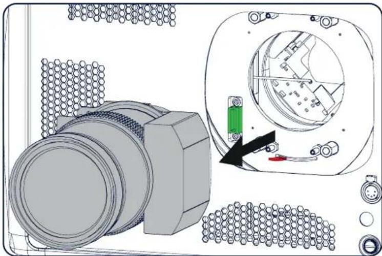
- Gently pull the lens out of the lens holder.
natural_image
Technical diagram of a mechanical assembly with a component, showing internal components and a highlighted section (no text or symbols present)Image 4-14
Lens removal

It's recommended to place the Lens caps of the original Lens packaging, back on both sides of the removed LenstoprotecttheopticsoftheLens.

It's recommended to place the foam rubber of the original projector packaging, back into the Lens opening to prevent intrusion of dust. Notethat this foam rubber is packed in a plastic bag to prevent the dust, emitted by the foam, from entering the projector.
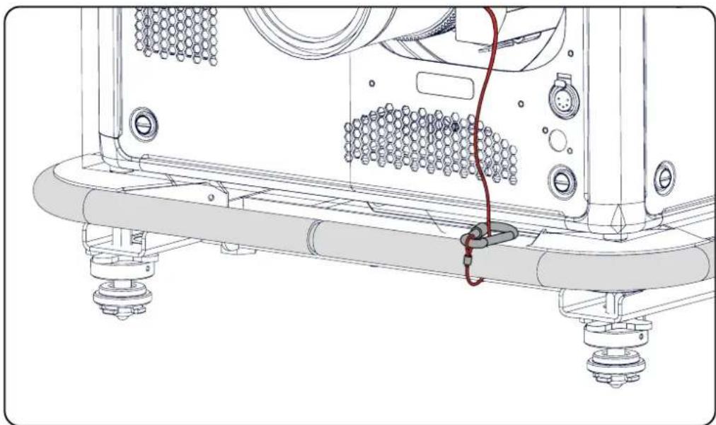
4.5 Lenssafetycable
Whenusingthesafetycable?
The lens safety cable must be used in any circumstances to protect a mounted lens in the lens holder when the projector is mounted above persons.
Necessaryparts
Safety cable: R9801079 (Barco order number)
Howtomountthecable
- Put the safety cable around the lens. Make sure the cable is mounted between the motor part and the mounting flange
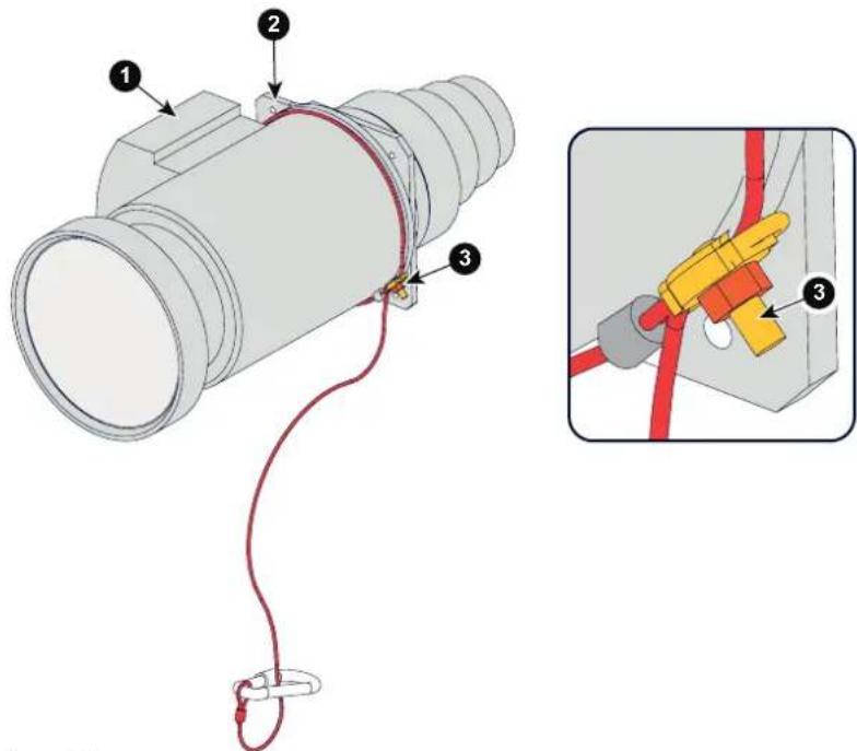
Image 4-15
Lens safety cable
1 Lens motor block
2 Mounting flange
3 C I a m p
- Insert both cable sides into the clamp;
Strap the cable and make sure that the clamp is positi oned on 45^ from the bottom to avoid interference of the cable with the lens locking mechanism.
Secure the cable by fixating the nut of the clamp.
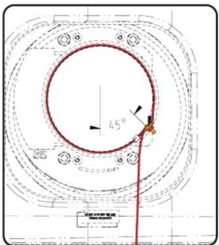
Image 4-16
Clamp position
- Turn the cable with hook lock around the carry handle and hook the hook lock around the cable.
natural_image
Technical line drawing of a mechanical assembly with no visible text or symbolsImage 4-17
4.6 Scheimpflugadjustment
Whathastobedone?
The lens holder has to be adjusted so that the "sharp focus plane" of the projected image falls together with the plane of the screen (Fp1→Fp2). This is achieved by changing the distance between the DMD plane and the lens plane (Lp1→Lp2). The closer the lens plane comes to the DMD plane the further the sharp focus plane will be. It can sometimes happen that you won't be able to get a complete focused image on the screen due to a tilt (or swing) of the lens plane with respect to the DMD plane. This is also known as Scheimpflug's law. To solve this the lens plane must be placed parallel with the DMD plane. This can be achieved by turning the lens holder to remove the tilt (or swing) between lens plane and DMD plane (Lp3→Lp4).
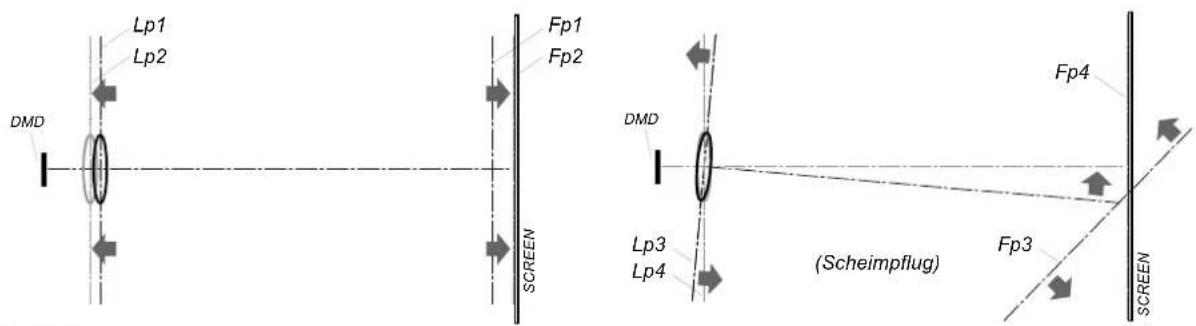
Image 4-18 Scheimpflug principle

Scheimpflugprinciple
The "plane of sharp focus" can be changed so that any plane can be brought into sharp focus. When the DMD plane and lens plane are parallel, the plane of sharp focus will also be parallel to these two planes. If, however, the lens plane is tilted with respect to the DMD plane, the plane of sharp focus will also be tilted according to geometrical and optical properties. The DMD plane, the principal lens plane and the sharp focus plane will intersect in a line below the projector for downward lens tilt.
Scheimpflugadjustmentpoints
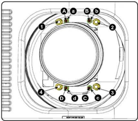
Image 4-19 Scheimpflug adjustments
IndicationondrawingFunction
4 Locking nut
1, 2 and 3 Scheimpflug adjustment nuts
A, B, C and D Set screws
a, b, c and d lock nuts
1, 2 and 3 are adjustment points.
4 is a locking point and NOT used during Scheimpflug adjustment.

CAUTION: In the HDX 4K, the Scheimpflug mechanism is positioned close to the actuator, which helps provide the 4k UHD images. To avoid damaging the actuator during Scheimpflug adjustment, it is important to havetheprojectorbein4kUHDmodeduringtheadjustment. This because the actuator will vibratewhile in 4kUHDmode.
IfoneoftheScheimphlugnutswouldtouchthevibratingactuatorduringadjustment,youwillhearaloud rattling noise. If heard, immediately turn the nut counterclockwise until you can no longer hear the noise.
Rememberandmarkthisposition,asthiswi ll be the innermost position this Scheimpflug nut will be able to achievewithoutdamagingtheactuator.
Necessarytools
• Allen key 3 mm
- Nut driver 13 mm
- Nut driver 10 mm
Howtoadjust
- Project a green focus pattern in 4K UHD.
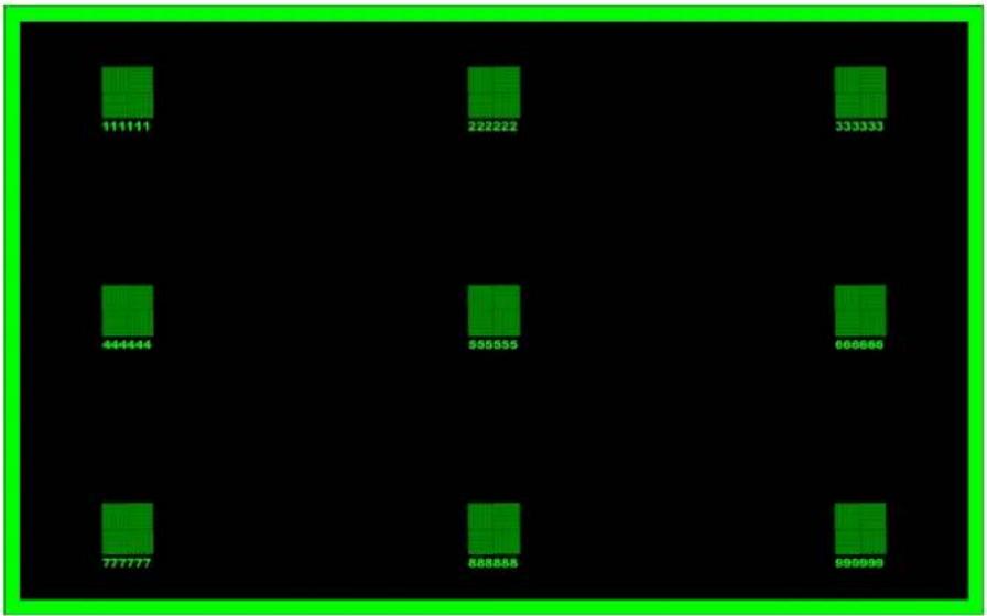
Image 4-20
- Loosen the lock nuts (a, b, c and d). See image 4-19.
- Loosen the 4 set screws (A, B, C and D) by 1 ~cm . See image 4-19.
- Fully loosen lock nut 4. See image 4-19.
- Optimize the focus of the projected image as follows:
a) Place the zoom lens in TELE position (smallest projected image) and adjust the focus using the lens focus barrel or motorized focus control.
b) Place the zoom lens in WIDE position (largest projected image) and adjust the focus by turning equally on nut 1, 2 and 3.
c) Repeat steps "a" and "b" until the projected image is as sharp as possible.
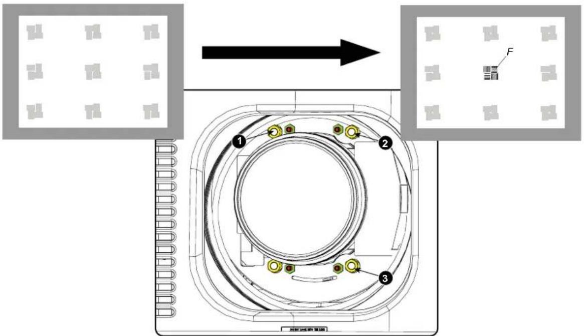
Image 4-21
Center focusing
- Sharpen bottom left corner of the screen by adjusting nut 1.
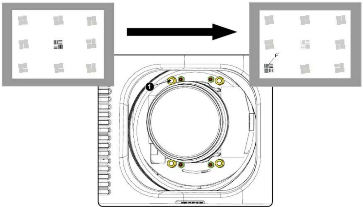
Image 4-22
Left bottom focusing
- Sharpen bottom right corner of the screen by adjusting nut 2.
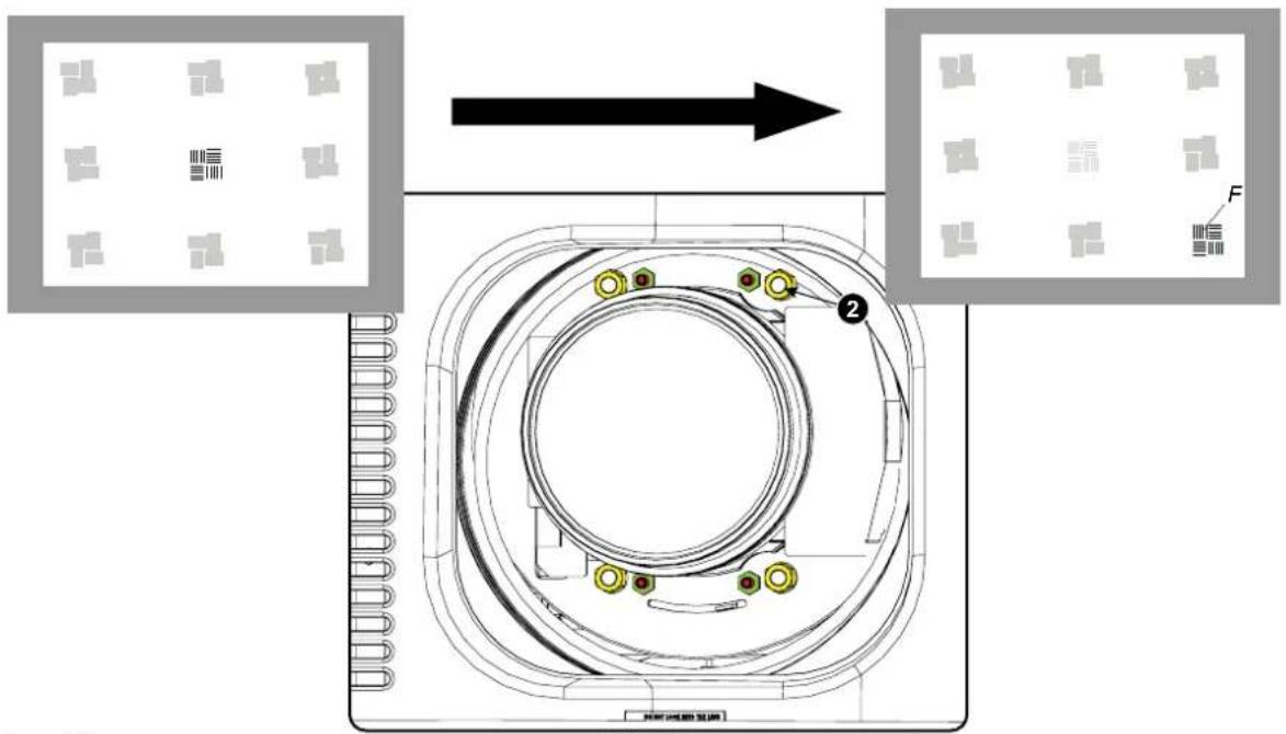
Image 4-23
Right bottom focusing
8. Sharpen top right corner of the screen by adjusting nut 3
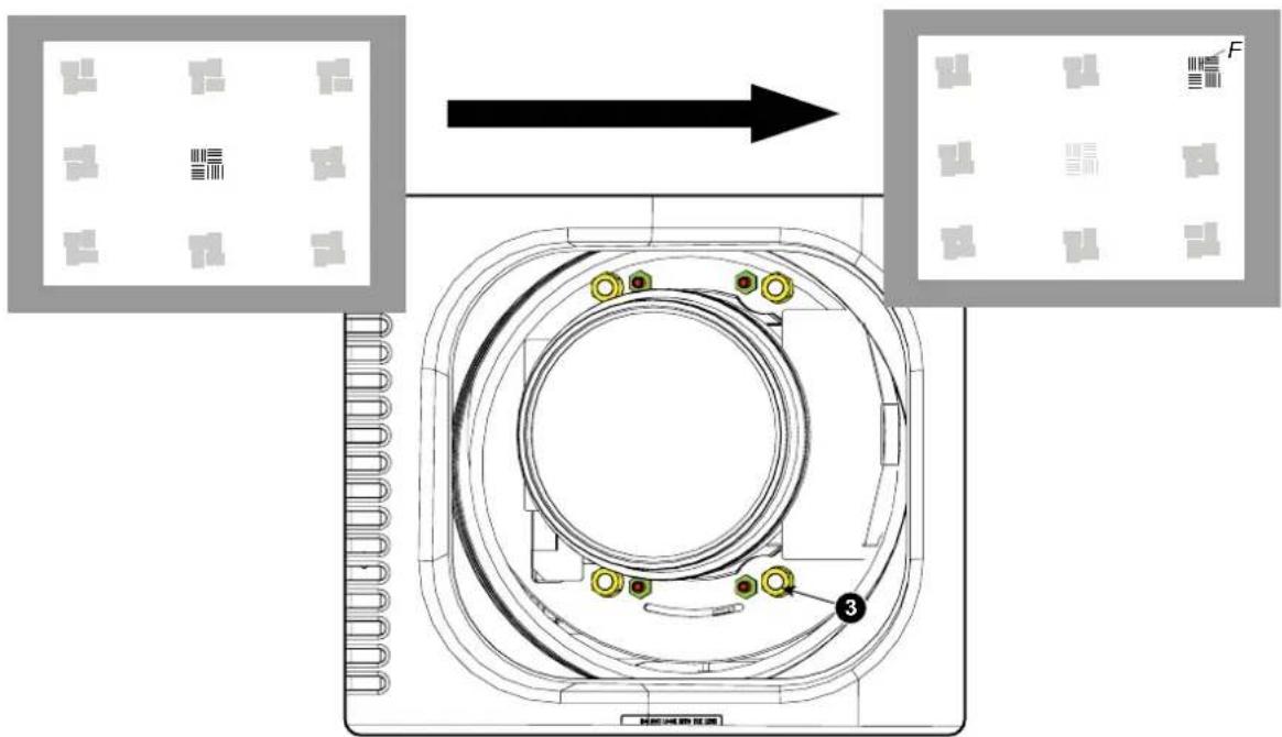
Image 4-24
Corner focusing
- Repeat from step 6 until the projected focus pattern is as sharp as possible in the center, left, right, top and bottom of the screen.
How to fix the Scheimpflug
Start the fixation as follows (steps must be followed strictly):
- Turn in set screw A, B and C. Tighten lightly (by hand).
Tip: Any movement of the image will affect the Scheimpflug adjustment - Fasten lock nuts a, b and c.
- Turn in set screw D lightly (by hand) allowing the image to move slightly (1/3 to 1/2 of a square).
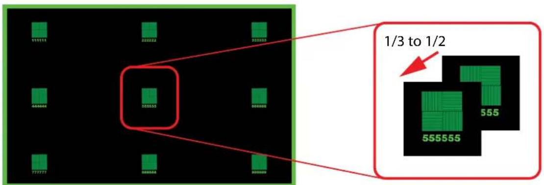
Image 4-25
-
Fasten lock nut d.
-
Tighten nut 4 until the offset of the image movement created in step 3 is canceled.
Tip: The amount of image movement in step 3 will determine how tight the nut in step 5 will need to be turned to return the imagetoitsoriginalposition.
5. INPUT&COMMUNICATION
Overview
- Introduction
- Input source connections
- Communication connections
• LED and Button indication chart
5.1 Introduction
General
The Input & Communication side of the projector consists of a local keypad, a communication panel, a venues & hospitality Input (V&H) and a free input slots. The free input slot can be used for optional modules (e.g. Virtual & Augmented Reality Input (V&AR)).
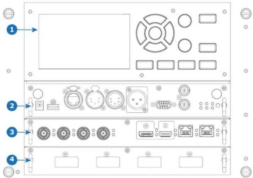
Image 5-1
1 Local Keypad and touch panel
2 Communication Panel
3 Venues & Hospitality Input (V&H)
4 Free input slot (here filled with the V&AR module)
5.2 Input source connections
Venues&HospitalityInput(V&H)

Image 5-2
1 Quad 3G SDI channel A Input
2 Quad 3G SDI channel B Input
3 Quad 3G SDI channel C Input
4 Quad 3G SDI channel D Input
5 DisplayPort Input
6 HDMI Input
7 HDBaseT Input 1
8 HDBaseT Input 2
Inputspecifications
• 3GSDI
3G follows the SMPTE 425M standard Level A.
HD-SDI follows the SMPTE 292M standard
• HDMI (High-Definition Multimedia Interface)
HDMI 1.4a. Support for 'Deep Color' up to 12 bit per color.
- DisplayPort
DisplayPort 1.2 (i.o. 1.1.a). Support for 'Deep Color' up to 12 bit per color.

CAUTION: The HDBaseT inputs can bridge a distance of 100 m but is sensitive to radiated electromagnetic interference: radiated electromagnetic interference (e.g. from GSM or switching inductive or capacitive loads) within the limits of electromagnetic compatibility requirements of 3 V/m can cause random flashes or temporary loss of the projected image.
As such, shielded CAT-6 cables with metal RJ-45 connectors are recommended; choose cable length no longer than required and route HDBT cable optimally screened from possible sources of electromagnetic emission.
Ethernetport
The projector can be connected to a LAN (local area network) using the Ethernet port on the communication interface. Once connected to the LAN, users are capable of accessing the projector from any location, inside or outside (if allowed) their company network using the control software: Projector Toolset. This toolset locates the projector on the network in case there is a DHCP server or the user can insert the correct IP-address of the projector to access the projector. Once accessed, it is possible to check and manipulate all the projector settings. Remote diagnostics, control and monitoring of the projector can then become a daily and very simple operation. The network connectivity permits to detect potential errors and consequently improve the time to servicing.
| 10/100Base-T—RJ45port | |
| PinDescription | |
| 1 | TXD+ |
| 2 | TXD- |
| 3 | RXD+ |
| 4 | — |
| 5 | — |
| 6 | RXD- |
| 7 | — |
| 8 | — |
Virtual&AugmentedRealityInput(V&AR)(Optional)

Image 5-3
1 Quad DisplayPort channel A Input
2 Quad DisplayPort channel B Input
3 Quad DisplayPort channel C Input
4 Quad DisplayPort channel D Input
Inputspecifications
All inputs are DisplayPort 1.2.
5.3 Communication connections
CommunicationPanel
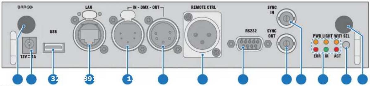
Image 5-4
1 Optional feature for future expansion
2 12V 1A output
3 USB backup custom settings
4 10/100 base-T for external control over IP and Art-Net
5 Feature for future expansion
6 Feature for future expansion
7 XLR input for wired projector control
8 RS232 for serial communication
9 Sync Out
10 Sync In
11 Status lights
12 IR receive sensor
13 Optional feature for future expansion
12Voutput
12 V output, maximum 1A, available when projector is not in stand by.
DMXinterface
DMX is used as communication bus between different devices in the light technic. Each device has an input and an output, so that the bus can be looped between the different devices. According to the standard a five wire cable with XLR connector is used.
You can use the DMX input port to connect a DMX device (DMX console) to the projector. This way you can control the projector from that DMX device (console). The DMX output port can be connected with the next device in the loop.
| Pin | Description |
| 1 | Earth |
| 2 | Cold |
| 3 | Hot |
| 4 | Return - (or not used) |
| 5 | Return + (or not used) |

DMX
DMX-512 Lighting protocol over RS-485 interface. Carries information of 512 channels from a lighting controller to lighting devices. Standardized by USITT.
RS232/RS422input
The communication interface of the HDX supports RS232 and RS422 serial communication on two different types of input connectors. The left one a Sub-D connector, the right one an USBB connector acting as RS input when connected to an USB input of a PC.
You can use the RS232/RS422 input to connect a local PC to your HDX. By this way you can configure and control your HDX from your local PC.
Advantages of using RS232/RS422 serial communication:
• easy adjustment of the projector via PC (or MAC).
- allow storage of multiple projector configurations and set ups.
• wide range of control possibilities.
• address range from 0 to 255.
• sending data to the projector (update)
• copying data from the projector (backup).
| RS232/422input(Sub-D)port | ||||||||||||||||
| PinDescription | ||||||||||||||||
| 1 | DCD : Data Carrier Detect | |||||||||||||||
| 2 | R | X | D | - | : | R | e | c | e | i | v | e | D | a | t | a |
| 3 TXD- : Transmitted Data | ||||||||||||||||
| 4 | DTR : Data Terminal Ready [RS232] | |||||||||||||||
| TXD+ : Transmitted Data [RS422] | ||||||||||||||||
| 5 | GND : Ground | |||||||||||||||
| 6 | DSR : Data Set Ready [RS232] | |||||||||||||||
| RXD+ : Received Data [RS422] | ||||||||||||||||
| 7 | — (not connected) — | |||||||||||||||
| 8 | CTS : Clear To Send | |||||||||||||||
| 9 RI : Ring Indicator | ||||||||||||||||

RS232
An Electronic Industries Association (EIA) serial digital interface standard specifying the characteristics of the communication path between two devices using either D-SUB 9 pins or D-SUB 25 pins connectors. This standard is used for relatively short-range communications and does not specify balanced control lines. RS-232 is a serial control standard with a set number of conductors, data rate, word length and type of connector to be used. The standard specifies component connection standards with regard to computer interface. It is also called RS-232-C, which is the third version of the RS-232 standard, and is functionally identical to the CCITT V.24 standard. Logical '0' is > + 3V, Logical '1' is < -3V. The range between -3V and +3V is the transition zone.

RS422
An EIA serial digital interface standard that specifies the electrical characteristics of balanced (differential) voltage, digital interface circuits. This standard is usable over longer distances than RS-232. This signal governs the asynchronous transmission of computer data at speeds of up to 920,000 bits per second. It is also used as the serial port standard for Macintosh computers. When the difference between the 2 lines is < - 0.2V that equals with a logical '0'. When the difference is > +0.2V that equals to a logical '1'..
USBport
The communication interface is equipped with a master USB port, type "A" connector. This USB port will simplify the service procedures for software updates or for taking backup files from the projector without network connection. An USB-stick is plugged into the USB port and files can be transferred from or to the projector using the local or remote control unit. Note that the USB-stick has to be Linux FAT16 compatible.
5.4 LEDandButtonindicationchart
Button BacklightStatus
| Button | Color status | Description |
Standby button | Blinking WHITE (slow) | Projector starts up (booting) |
| Blinking WHITE (fast) | Firmware upgrade | |
| Solid WHITE | Projector is in Standby mode | |
| Blinking BLUE | Projector goes to ON mode | |
| Solid BLUE | Projector is ON | |
| Blinking RED | Error condition | |
Shutter button | Off (no color) | Projector is OFF, starts up, or is in Standby mode. |
| Solid WHITE | Projector is ON, shutter is open | |
| Solid RED | Projector is ON, shutter is closed |
LEDStatus
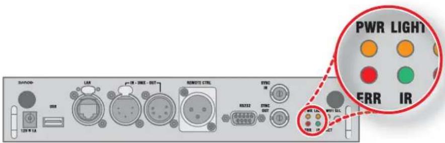
| LEDColorstatusDescription | ||
| PWR (power LED) | Off Projector powers up | |
| RED Projector is in Standby | ||
| ORANGE Projector is Ready | ||
| GREEN Projector is on | ||
| LIGHT (Illumination LED) | Off Lamp is off | |
| RED No lamp inserted | ||
| ORANGE Lamp is on in ECO mode | ||
| GREEN | Lamp is on in normal mode | |
| GREEN-ORANGE Lamp is on in CLO mode | ||
| ERR (error LED) | Off No error | |
| Blinking Orange (fast) Firmware upgrade | ||
| RED toggles on/off Error | ||
| ORANGE toggles on/off Warning | ||
| RED IR signal receivedIR | ||
| GREEN IR signal acknowledged |
6.GETTINGSTARTED
Howcontrollingtheprojector?
The projector can be controlled by the local keypad, by the remote control unit or by browser application.
Locationofthelocalkeypad?
The local keypad is located on the input side of the projector.
Remotecontrolfunctions.
This remote control includes a battery powered infrared (IR) transmitter that allows the user to control the projector remotely. This remote control is used for source selection, control, adaptation and set up.
Other functions of the remote control are :
- switching between stand by and operational mode.
- switching to "pause" (blanked picture, full power for immediate restarting)
- direct access to all connected sources.
Overview
• Functionality overview
- Power on projector
- Switching to standby
- Power off projector
- Using the RCU
6.1 Functionalityoverview
LocalKeypadoverview
1 Menu Selection.
2 Menu Activation.
3 OSD On/Off.
4 Menu Back.
5 Power On/Off.
6 Touch Panel On/Off.
7 Input Selection.
8 Shutter Open/Close.
9 Test Patterns.
10 Lens Menu.
11 Touch Panel.
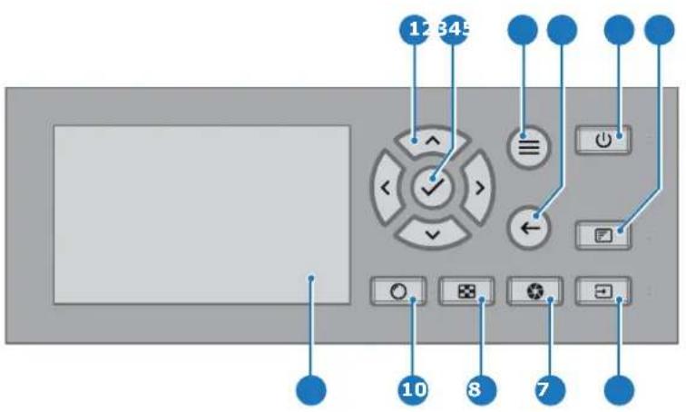
RemoteControlUnitbuttons
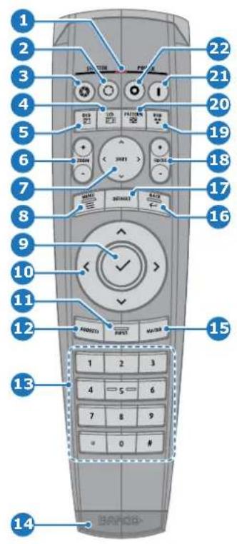
1 Button pressed indicator.
2 Shutter Open.
3 Shutter Close.
4 Touch Panel On/Off.
5 OSD On/Off.
6 Lens Zoom.
7 Lens Shift.
8 Menu Activation.
9 Menu Selection.
10 Menu Navigation.
11 Input Selection.
12 Address button.
13 Numeric buttons.
14 XLR connector.
15 Macro button.
16 Menu Back.
17 Default button.
18 Lens Focus.
19 Color On/Off.
20 Test Patterns.
21 Power On.
22 Power Off.
23 Stereo Jack.
24 RCU On/Off.
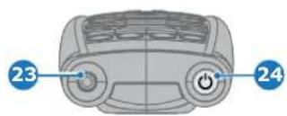
6.2 Poweronprojector
Howtopoweron.
- Press the mains switch at the back of the projector to switch on this projector.
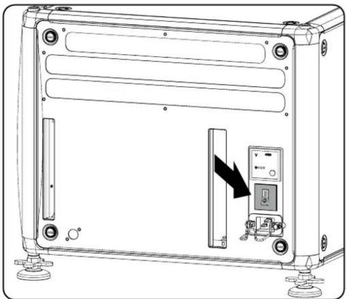
natural_image
Technical line drawing of a device rear panel with a black arrow indicating a switch or adjustment (no text or symbols present)Image 6-1
Main switch
- When '0' is pressed, the projector is switched off.
- When 'I' is pressed, the projector is switched on.
The projector starts up to standby mode. The Power on/off button will blink until standby mode is achieved. Once in standby mode, the Power on/off button will be lit WHITE, but the display will be off.
- Press the Power on/off button on the projector, or the Power On button on the remote control.
The projector will continue to power on mode. The Power on/off button will blink until the projector is ready. Once the projector is ready, the Power button will be lit BLUE.
The start up screen is displayed on the touch panel and when fully started up, it changes to the overview screen.
The current mains input voltage is indicated on the voltmeter just above the powers switch.

The background image of the startup screen and info screens can be changed with Projector Toolset with an installedHDXplug-in.
Statusoverview
Once the projector is started, press Status to get an overview of parameters such as :
- Chosen source
• Current resolution and refresh rate
• Device serial number and article number - Current firmware version and model name
• Current illumination (in percentage) - Lamp runtime in hours
- Chosen communication method and IP address (if connected)
- Warpstatus
• Environmental temperature
Startingimageprojection
- Make sure the available sources are connected to the appropriate input ports.
- Press the Input Selection button on the keypad or on the remote control until:
- the LED of the selected source lit up GREEN, and
- the image of the selected source is projected.
flowchart
graph LR
    A["Input"] --> B["Process Step"]
    B --> C["Output"]
Image 6-3
6.3 Switching to stand by
Howtoswitchtostandby
- Press and hold the Power on/off button for 3 seconds on the local keypad, or press the Power Off button on the remote control. The projector goes to standby mode. The after-cooling cycle will start (up to 300 seconds). During this period the Power on/off button will blink. Once the after-cooling cycle has ended, the projector will be in standby mode and the Power on/off button will be lit WHITE.
flowchart
graph LR
    A["Hand press icon 3 s"] --> B["Four-panel propeller"]
    B --> C["Power switch icon 300 s"]
    C --> D["Battery icon 300 s"]
Image 6-4
6.4 Poweroffprojector

CAUTION: This procedure assumes the projector is in standby mode.
Howtopoweroff
- Switch off the projector with the mains switch. '0' must be pressed.
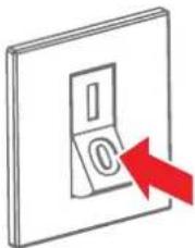
natural_image
Simple line drawing of a switch with a red arrow pointing to the button (no text or symbols)Image 6-5
- Unplug the power cord from the projector.
6.5UsingtheRCU
Pointingtothereflectivescreen
- Point the front of the RCU to the reflective screen surface.
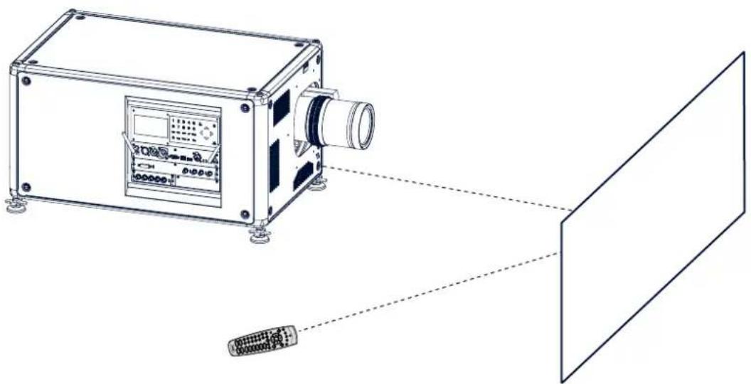
natural_image
Technical line drawing of a device connected to a screen, showing no text or symbols present.Image 6-6 IR control via reflective screen
HardwiredtotheXLRinput
- Plug one end of the remote cable in the connector on the bottom of the RCU.
- Plug the other end in the big connector on the communication interface of the projector, labelled Remote CTRL.
PointingdirectlytothelRsensor
When using the wireless remote control, make sure you are within the effective operating distance (30m, 100ft in a straight line). The remote control unit will not function properly if strong light strikes the sensor window or if there are obstacles between the remote control unit and the projector IR sensor.
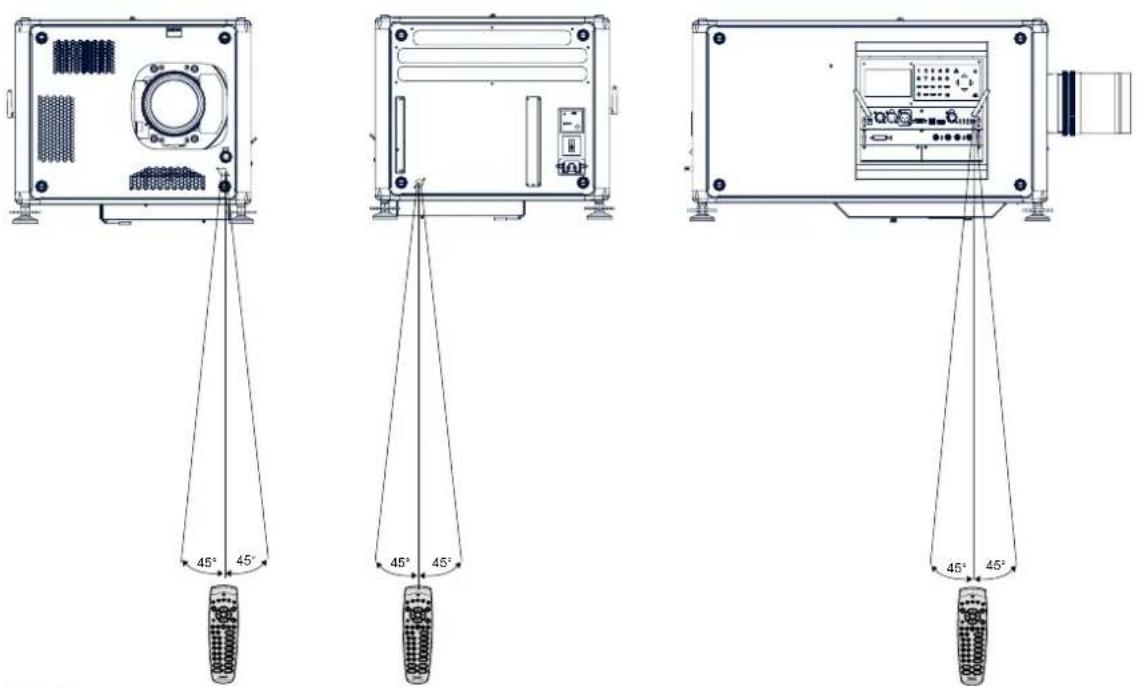
Image 6-7 RCU to one of the IR sensors
7. GRAPHICUSERINTERFACE(GUI)
Overview
• O v e r v i e w
- Navigation
- Test Patterns
7.1Overview
GUI-MainMenuoverview
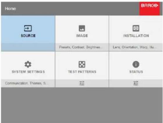
Image 7-1
Home menu
7.2Navigation
NavigationviatheRCUorlocalkeypad
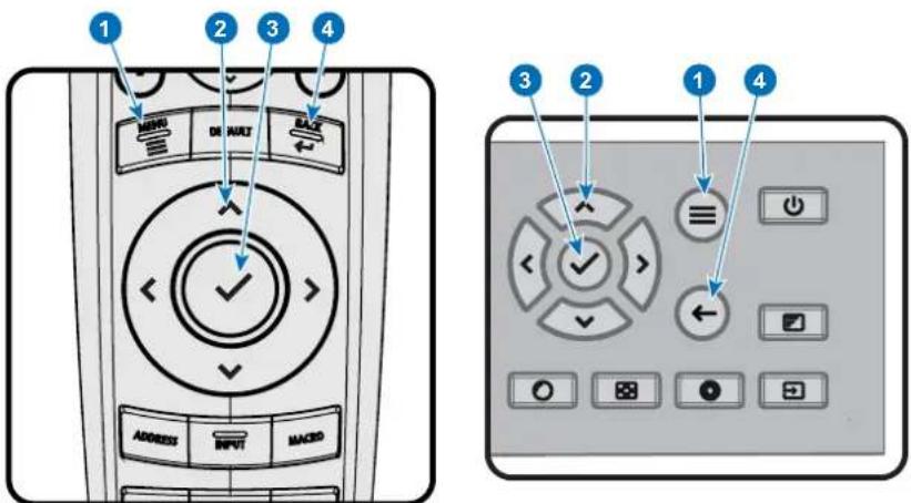
Image 7-2
To start up the menu structure, press MENU (1).
Use the arrow keys (Menu Navigation buttons) to navigate to the desired menu item (2). The background color changes to light blue.
Press the Menu Selection button (center key of the arrow keys) to activate that item and to jump one level deeper (3).
Press the Back button to go up one level (4).
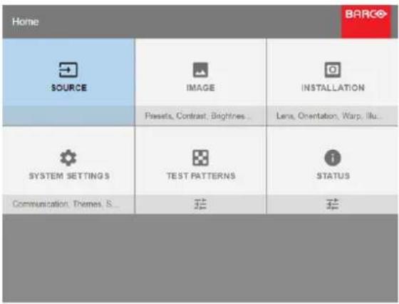
Image 7-3
Home menu
7.3TestPatterns
Howtousetestpatterns
- In the main menu, select TestPatterns.
Or, Push the Test Patterns button on the RC or on the local keypad.
Image 7-4 Main menu, Test Patterns
-
In the Test Patterns menu, select either Internal, or Output test patterns.
-
In the chosen submenu, select the desired test pattern from the list.
You can select one of the following Internal test patterns:
- Convergence 1 / 2
- Focus Green
You can select one of the following Output test patterns:
- Vertical / diagonal lines
- Step bar
- Blemish zone
- Checkerboard
- Color bars
- Convergence
- FIP
- Full screen black / white / blue / green / red / cyan / magenta / yellow
- Grid
- Vertical Ramp
- Horizontal Ramp
- MTF
- To turn the test pattern off, return to the previous menu.
8. GUI-SOURCE
Overview of features
- Source Selection
- Connector Settings
8.1 SourceSelection
Howtoselect?
- Press Menu to activate the menus and select Source.
Image 8-1 Select Source
- Press ENTER.
The Select Source menu is displayed with the actual available sources filled out.
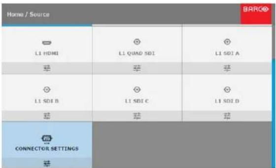
Image 8-2 Input selection
- Select the desired input.
8.2 Connector Settings
Howtoconfiguretheconnector
- Press Menu to activate the menus and select Source.
Image 8-3 Select Source
- Press ENTER.
The Select Source menu is displayed with the actual available sources filled out.
- Scroll down to the bottom of the list and select Connector Settings.
Image 8-4
- Select the desired connector.
The Connector Settings menu for this connector will be displayed. All default values are Auto.

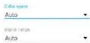
Image 8-5
- To apply a limit on the used color space, select one of the other values in Color space.
- To apply a limit on the used signal range, select one of the other ranges in Signal Range.
9. GUI-IMAGE
Overview of features
- Setting image levels manually
• P7 Realcolor - Setting the output resolution
9.1 Settingimagelevelsmanually
Purpose
Contrast: Change the contrast of the complete output signal (main and PiP window together) of the projected image. Brightness: Change the brightness of the complete output signal (main and PiP window together) of the projected image. Saturation: Change the saturation of the complete output signal (main and PiP window together) of the projected image.
HowtosetupContrast
- In the main menu, select Image → Contrast.
Image 9-1 Image menu — Contrast
- Use the ◀ or ▶ key to change the contrast enhancement until the desired value is reached (adjustable between 0 and 2).
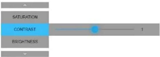
Image 9-2 Contrast slider
- Use the ▲ or ▼ key to select Saturation or Brightness.
HowtosetupBrightnessLevel
- In the main menu, select Image → Brightness.
Image 9-3 Image menu — Brightness
- Use the ◀ or ▶ key to change the contrast enhancement until the desired value is reached (adjustable between -1 and 1).
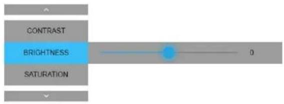

HowtosetupSaturationLevel
- In the main menu, select Image → Saturation.
Image 9-5 Image menu — Saturation
- Use the ◀ or ▶ key to change the contrast enhancement until the desired value is reached (adjustable between 0 and 2).
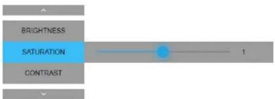

9.2P7Realcolor
Purpose When blending images from multiple projectors, the measured color coordination values of each projector can be altered to a desired common level. This so that the projected colors are identical over all projectors used.
Purpose When blending images from multiple projectors, the measured color common level. This so that the projected colors are identical over
HowtosettheP7desiredvalu es
- In the main menu, select Image → Advanced → P7 Realcolor.
Image 9-7 Advanced menu — P7 Realcolor
The P7 menu is displayed.
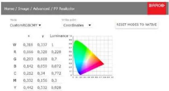
heatmap
| | x | y | Luminance | |---|---|---|---| | W | 0,318 | 0,337 | 1 | | R | 0,666 | 0,328 | 0,228 | | G | 0,293 | 0,668 | 0,7 | | B | 0,142 | 0,059 | 0,072 | | C | 0,212 | 0,34 | 0,772 | | M | 0,332 | 0,156 | 0,3 | | Y | 0,442 | 0,532 | 0,928 |Image 9-8 P7 Realcolor menu
-
Select the desired Mode. Choose one of the following:
-
Native: Default mode, with default values. All other options in the P7 menu are disabled.
- Custom RGB: 3-point color configuration. In RGB mode, the C, M and Y coordinates will be calculated automatically based on the R, G and B coordinates.
- Custom RGBCMY: 6-point color configuration (both RGB and CMY). In RGBCMY mode, each color can be given a specific coordinate within the measured color triangle.
-
Custom WHITE: Configure only the White temperature.
-
Click on White point and choose one of the following:
-
Coordinates: Configure the white point via specific coordinates
-
Temperature: Configure the white point via a temperature slider
-
Define the coordinates for each available color.
Note: You can only pick coordinates within the measured color triangle.

YoucanresetallcoordinatestothedefaultvaluesbyclickingontheResetbutton.
9.3 Settingtheoutputresolution
Howtochooseoutputresolution
- In the main menu, select Image → Advanced → Output resolution.
Image 9-9 Advanced menu — Output resolution
-
Select the desired output resolution. Possible Resolutions:
-
4K UHD: 4K images, using the actuator.
- WQXGA: 2K image. In this mode, the actuator is disabled.
10. GUI-INSTALLATION
Overview of features
• C o n figuring the lens
- Orientation
- Warping
- Lamp illumination
10.1Configuringthelens
Whatcanbedone?
Once a lens has been installed in the projector, you can fine-tune the projected image.
The following things can be configured possible:
- Correcting the lens zoom and focus.
- Shifting the lens position.
• High Contrast mode
Howtoconfigurethelens
- In the main menu, select Installation → Lens.
Image 10-1 Installation menu — Lens Options
- To change the focus and zoom, select Zoom focus.
Image 10-2 Lens menu, Focus & Zoom
- Use the ▲ or ▼ key to zoom the lens in or out. Use the ◀ or ▶ key to focus the lens to far or near.
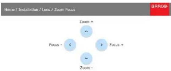
flowchart
graph TD
    A["Home / Installation / Lens / Zoom Focus"] --> B["Zoom +"]
    B --> C["Focus -"]
    C --> D["Focus +"]
    D --> E["Zoom -"]
Image 10-3 Zoom and focus adjustment
- To change the position of the projected image, select Shift in the Lens menu.
Image 10-4
Lens menu, Lens shift
- Use the ▲ or ▼ key to shift the lens in vertical direction.
Use the ◀ or ▶ key to shift the lens in horizontal direction.
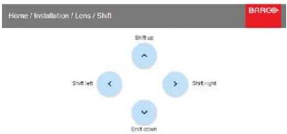
flowchart
graph TD
    A["Shift up"] --> B["Shift left"]
    B --> C["Shift right"]
    C --> D["Shift down"]
Image 10-5
Shift adjustment
- To (de)activate high contrast mode, select High Contrast in the Lens menu.
Image 10-6
- Click on or off to activate / deactivate high contrast mode.
10.2Orientation
Whatcanbedone?
The way of physical installation of the projector can be defined to the projector.
The following installation are possible:
- front/table
- front/ceiling
- rear/table
- rear/ceiling
Howtosetthecorrectorientation
- In the main menu, select Installation → Orientation.
Image 10-7
Installation menu, Orientation
The Orientation menu is displayed.
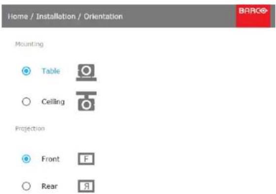
Image 10-8
Orientation menu
- Use the ▲ or ▼ key to select the desired mounting position and press ENTER to activate. Use the ▲ or ▼ key to select the desired projection position and press ENTER to activate.
10.3Warping
10.3.1 Aboutwarping
Overview
Image warping is the process of digitally manipulating an image to compensate for the distortion of the screen. Consequently, it can also be used to generate an image with irregular shape.
While an image can be transformed in various ways, pure warping doesn't affect the colors.
10.3.2 Warping-ScreenSize
AboutScreenSizeadjustment
If the used screen or projected area is not a standard size, you can adjust the projected image to perfectly fit the screen/area.
Note that Screen Size adjustment is not the same as zooming in or out. If an non-standard screen/area is used, it is better to first use the Zoom and focus functions to match the projected image to the target area as closely as possible. Only after this is done, you can shrink either the width or height to obtain a perfect match.
Howtoadjusttheimage?
- In the main menu, select Installation → Warp.
Image 10-9
Installation menu, Warp
- In the Warp menu, select Screen Size.
Image 10-10
Warp Menu, Screen Size
The Screen Size menu is displayed.
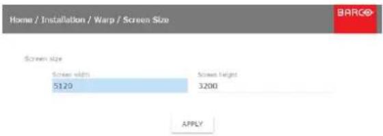
Image 10-11
Screen Size menu
-
Select either Screen width or Screen height.
-
Set the new value to shrink either the width or height of the projected image and confirm.
Tip: A red border corner will be projected along with the current image. The border is a visual aid, showing the result of the adjusted screensize.
10.3.3 Warping-4cornersadjustment
About4Cornersadjustment
4 corner adjustment is typically used when the mechanical installation of the projector prevents it from pointing perpendicularly at the screen. For example, you can overshoot the screen and use 4 corner adjustment to pull your projected image corners back into the screen.
Howtoadjusttheimage?
- In the main menu, select Installation → Warp.
Image 10-12
Installation menu, Warp
- In the Warp menu, select 4 Corners.
Image 10-13
Warp menu, 4 Corners
The 4Corners menu is displayed.
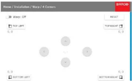
Image 10-14 4Comers Warping
- To enable warping, make sure the Enable slider is set active.
- To set warping on one or more of the four corners, select one of the four corners.
- Set the desired X and Y coordinates for this corner, using the arrow keys. Tip: A red border corner will be projected along with the current image. The border is a visual aid, showing the result of the warped corners.
- Repeat steps 4 and 5 for each corner, until all corners are warped in the desired position.
10.4 Lampillumination
Whatcanbedone?
Within a certain power mode, the light output of the lamp can be reduced by reducing the lamp power
Howtoreducethepower
- In the main menu, select Installation → Illumination.
Image 10-15 Installation menu, Illumination
- In the Illumination Menu, select Power.
Image 10-16 Illumination menu, Power
- Use the Slider to change the power value.
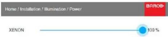
Image 10-17
Lamp Power Adjustment
11. GUI-SYSTEM SETTINGS
Overview of features
- Communication
- Themes
- Service Menu
- R e s e t
11.1 Communication
Aboutanetworkconnection
A network connection can be made via a wired connection or via the optional wireless unit.
11.1.1 Introduction to a Network connection

DHCP
Dynamic host configuration protocol. DHCP is a communications protocol that lets network administrators manage centrally and automate the assignment of IP addresses in an organization's network. Using the Internet Protocol, each machine that can connect to the Internet needs a unique IP address. When an organization sets up its computer users with a connection to the Internet, an IP address must be assigned to each machine. Without DHCP, the IP address must be entered manually at each computer and, if computers move to another location in another part of the network, a new IP address must be entered. DHCP lets a network administrator supervise and distribute IP addresses from a central point and automatically sends a new IP address when a computer is plugged into a different place in the network.

IP
Internet Protocol. The network layer of TCP/IP. Required for communication with the internet.

Subnetmask
A number that is used to identify a subnetwork so that IP addresses can be shared on a local area network.

DefaultGateway
A router that serves as an entry point into and exit point out of a network. For example, a local network (LAN) may need a gateway to connect it to a wide area network (WAN) or to the Internet.

MACaddress
Media Access Control address. Unique hardware number, used in combination with the IP-address to connect to the network (LAN or WAN).
WhatshouldbesetupforanEthernetaddress?
Two ways can be used to assign an address:
• use the Automatic setting so that an automatic address will be assigned.
- Assign manually an IP address, Net-mask (subnet-mask), (default) gateway address.
- Set the IP-Address field to the desired value. This must NOT be 0.0.0.0 for static IP-Address assignment. The IP address identifies a projector's location on the network in the same way a street address identifies a house on a city block. Just as a street address must identify a unique residence, an IP address must be globally unique and have a uniform format.
- Set the Subnet-Mask as appropriate for the local subnet.
- Set the Default-Gateway to the IP-Address of the local router (MUST be on the local subnet!) on the same network as this projector that is used to forward traffic to destinations beyond the local network. This must not be 0.0.0.0. If there is no router on the projector's local subnet then just set this field to any IP-Address on the subnet.
11.1.2 WiredIPaddresssetup
HowtomanuallysetupthelPaddress
- In the main menu, select System Settings → Communication.
Image 11-1
- In the Communication menu, select LAN.
Image 11-2
Communication menu, LAN
The LAN menu is displayed
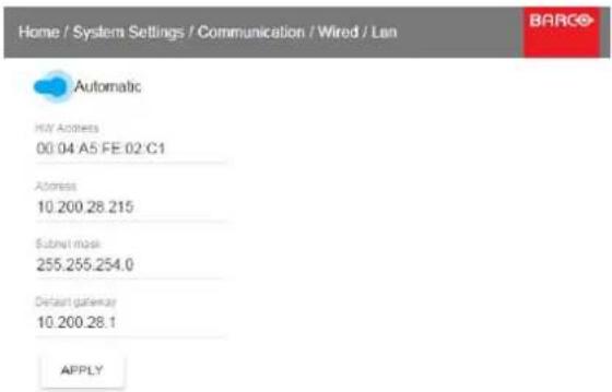
Image 11-3
LAN menu
- In the LAN menu, make sure that Automatic is disabled.
- Use the ▲ or ▼ key to select Address and press ENTER to activate the input box.
- Use the ▲ or ▼ key to change the selected character.
Use the ◀ or ▶ key to select another character.
Note: Digits can be entered with the digit keys on the remote control or the local keypad. When a digit is entered in that way, then next character will be selected automatically.
- Repeat steps 4 and 5 for the Subnet and Default Gateway.
- Click APPLY to confirm all changes.
11.2 Themes
Howtoselectadifferentinterfacet heme
- In the main menu, select System Settings → Themes.

THEMES
Light, Dark
Image 11-4
System Settings Menu — Themes.
- In the themes menu, select the desired Theme.
You can choose one of the following: Light, or Dark.
11.3ServiceMenu
11.3.1 Service-Color

CAUTION: The native colors have been measured and set during factory production. Do not change them, unless part of the optical path have been replaced due to servicing.
If you need to change the native colors on the device, make sure to also performaP7calibration, using the ProjectorToolsetandachromameter. FormoreinfoonP7calibration, refertotheProjectorToolsetReference guide.
Howtoadjust the P7nativesettings
- In the main menu, System Settings → Service.

SERVICE
Color Wheel, Color, Statistic...
Image 11-5
- Enter the service password.
- In the Service menu, select Color.
Image 11-6
The Color menu will be displayed.

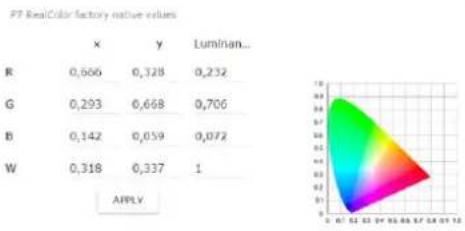
other
P7 RealColor factory native values | | x | y | Luminan... | |---|---|---|---| | R | 0,666 | 0,328 | 0,232 | | G | 0,293 | 0,668 | 0,706 | | B | 0,142 | 0,059 | 0,072 | | W | 0,318 | 0,337 | 1 | APPLYImage 11-7
-
Select the desired value to change and confirm.
-
Change the values to the desired position, taking into account the color gamut values.
11.3.2 Service-Statistics
Whatcanbeseen?
The identification screen shows the general information about the projector.
The following items will be displayed:
- Lamp on runtime
- Lamp Strike
- Projector Runtime
- System time
- Current Uptime
Howtodisplaytheststatistics
- In the main menu, System Settings → Service.
Image 11-8
- Enter the service password.
- In the Service menu, select Statistics.
Image 11-9
The Statistics will be displayed.
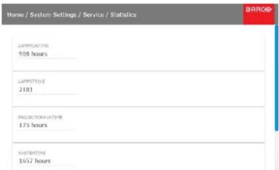
Image 11-10
11.3.3 Lens Calibration

Lenscalibrationisatimeconsumingoperation.
Howtocalibrate
- In the main menu, System Settings → Service.

SERVICE
Color Wheel, Color, Statistic...
Image 11-11
- Enter the service password.
- In the Service menu, select Lens Calibration.
Image 11-12
System Settings menu — Lens Calibration
The Lens Calibration menu is displayed.
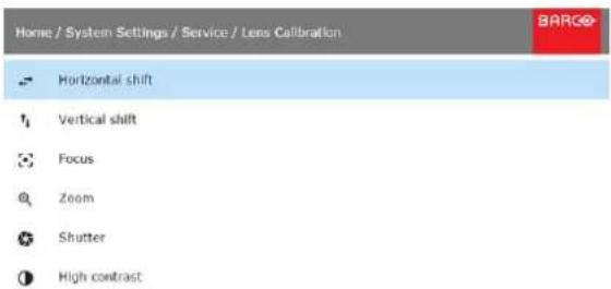
Image 11-13
Lens Calibration menu
- In the Lens Calibration menu, click the desired calibration action.
You can select one of the following:
- Horizontal shift
- Vertical shift
- Focus
- Zoom
- Shutter
- High contrast
The text Calibration in progress will be displayed until the calibration is completed.
11.4Reset
Whatcanbedone?
All settings and values on the projector can be reset to its default values. This can be done for one or more settings separately, or all settings together (factory reset).
Howtoresetoneormoreprojectorsettings
- In the main menu, select System Settings → Reset.
Image 11-14 System Settings menu, Reset
The Reset menu is displayed.
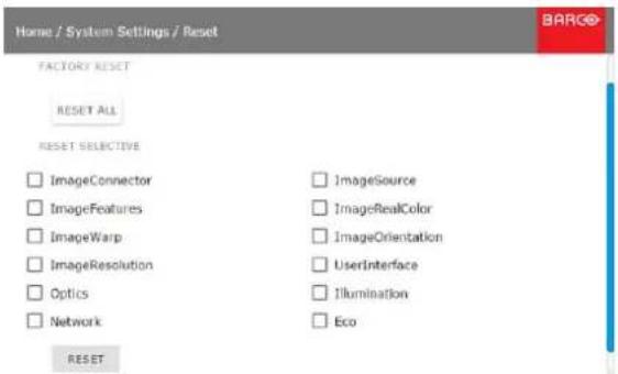
Image 11-15 Reset menu
- Select the checkbox next to the settings that need to be reset.
- Click RESET to reset all selected settings.
Howtoresetallprojectorsettings
- In the main menu, select System Settings → Reset.
- In the Reset menu, click RESET ALL.
12.MAINTENANCE
Aboutthischapter
This chapter contains general maintenance procedures.
Overview
- Cleaning the lens
- Cleaning the exterior of the projector
12.1 Cleaningthelens

To minimize the possibility of damage to optical coatings, or scratches to lens surfaces follow the cleaning procedure as described here precisely.
Necessarytools
- Compressed air.
- Clean Toraysee® cloth or any micro fiber lens cleaning cloth.
- Clean cotton cloth.
Necessaryparts
Lens cleaner (e.g. Carl Zeiss lens cleaner or Purasol® or any water-based lens cleaner)
Howtocleanthelens?
- Blow off dust with clean compressed air (or pressurized air cans ^1 ).
- Clean with lens cleaner together with a clean lens cleaning cloth to remove the dust and contamination. Use big wipes in one single direction.
Warning: Do not wipe back and forwards across the lens surface as this tends to grind dirt into the coating. - Use a dry lens cleaning cloth to remove left liquid or stripes. Polish with small circles.
- If there are still fingerprints on the surface, wipe them off with lens cleaner together with a clean lens cleaning cloth. Polish again with a dry one.

If smears occur when cleaning lenses, replace the cloth. Smears are the first indication of a dirty cloth.
12.2 Cleaningtheexterioroftheprojector
Howtocleantheexterioroftheprojector?
- Switch off the projector and unplug the projector from the mains power net.
- Clean the housing of the projector with a damp cloth. Stubborn stains may be removed with a cloth lightly dampened with a mild detergent solution.
13.SERVICING


Make sure the module seats in its sliders (2).
Pull in the module until the contacts (3) are fully inserted into the connectors.
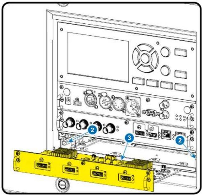
Image 13-2
Insert input module
- Fixate the 3 fixation screws (4).
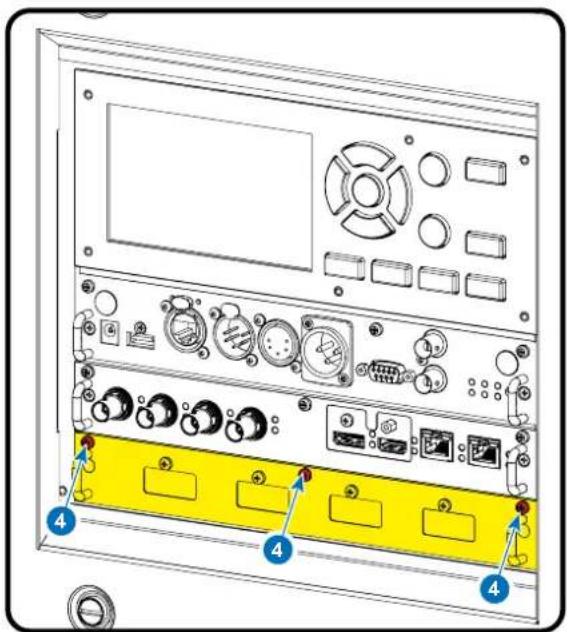
Image 13-3
Fixate input module
13.2 Removal of the front cover

WARNING: Switch off the projector and unplug the power cord before starting the procedure.
Necessarytools
7 m m flat screw driver
Howtoremove
- Remove the lens. See "Lens removal", page 33.
- Remove the rubber dust ring from the lens holder.
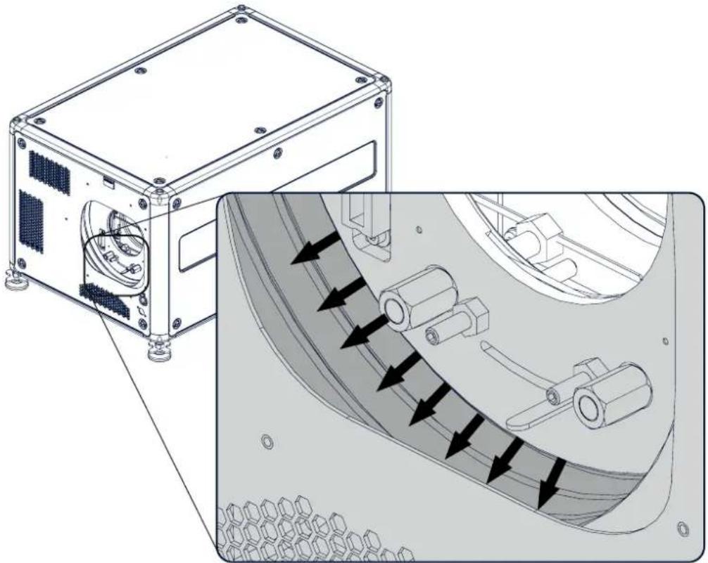
natural_image
Technical illustration of a mechanical device with internal components and directional arrows indicating flow or movement (no text or symbols present)Image 13-4
Dust ring removal
- Release the 4 captive screws (1).
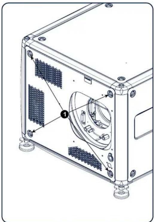
natural_image
Technical line drawing of a mechanical device with labeled components (no text or symbols present)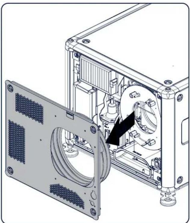
natural_image
Technical line drawing of an internal mechanical assembly with a panel and housing (no text or symbols)Image 13-5
Front cover removal
- Take off the front cover.
13.3Mountingthefrontcover

WARNING: Switch off the projector and unplug the power cord before starting the procedure.
Necessarytools
7 m m flat screw driver
Howtomount
- Place the front cover with the rubber dust facing the projector on its place.
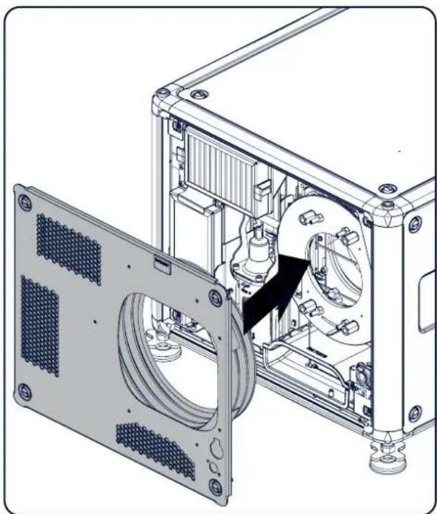
natural_image
Technical diagram of an internal mechanical assembly with a panel and housing, showing no text or symbols.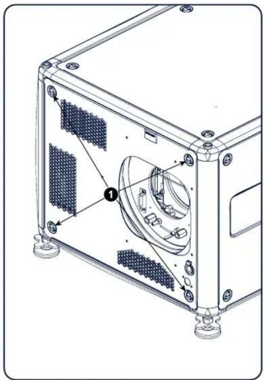
natural_image
Technical line drawing of a mechanical device with labeled components (no text or symbols present)Image 13-6 Mount front cover
- Secure the 4 captive screws (1).
- Reinstall the rubber dust ring around the lens holder.
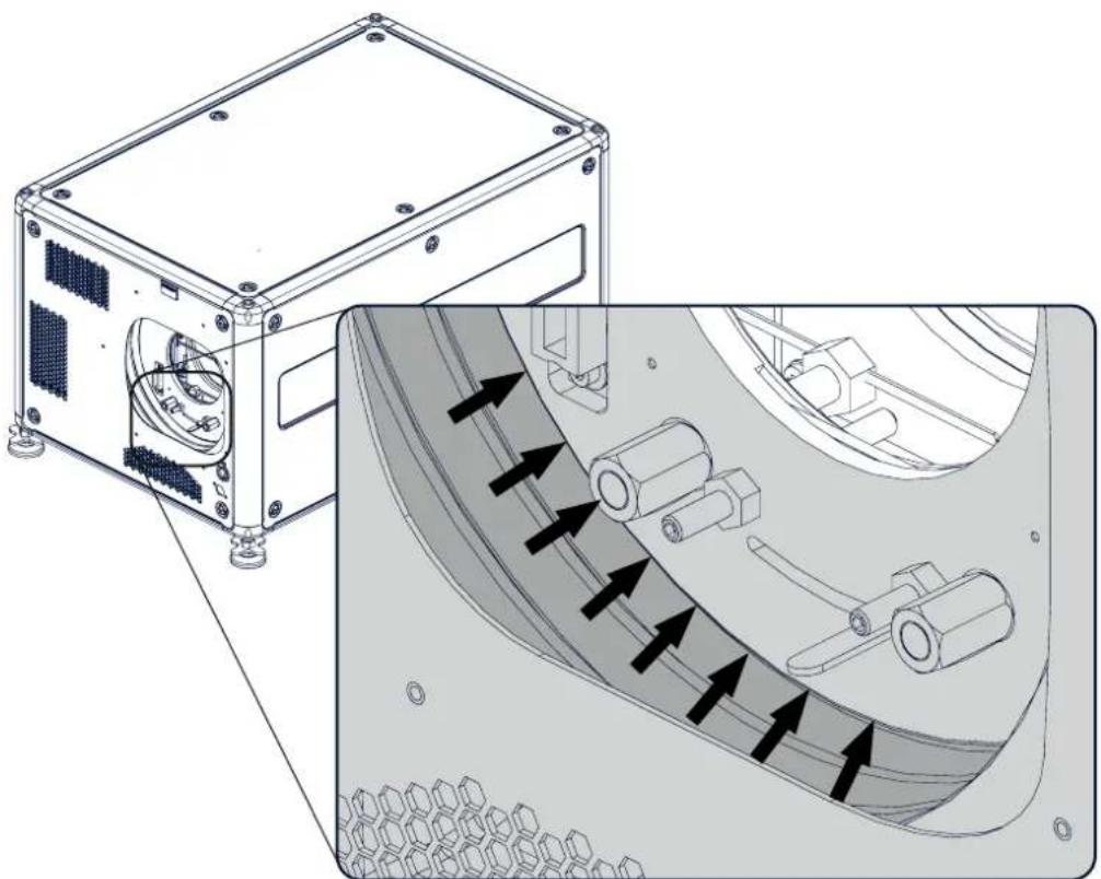
natural_image
Technical illustration of a mechanical device with internal components and directional arrows indicating flow or movement (no text or symbols present)Image 13-7
Mount dust ring
4. Mount lens again.
13.4Removalofthelampcover

WARNING: Switch off the projector and unplug the power cord before starting the procedure.
Necessarytools
7 m m flat screw driver
Howtoremove
- Release the 6 captive screws.
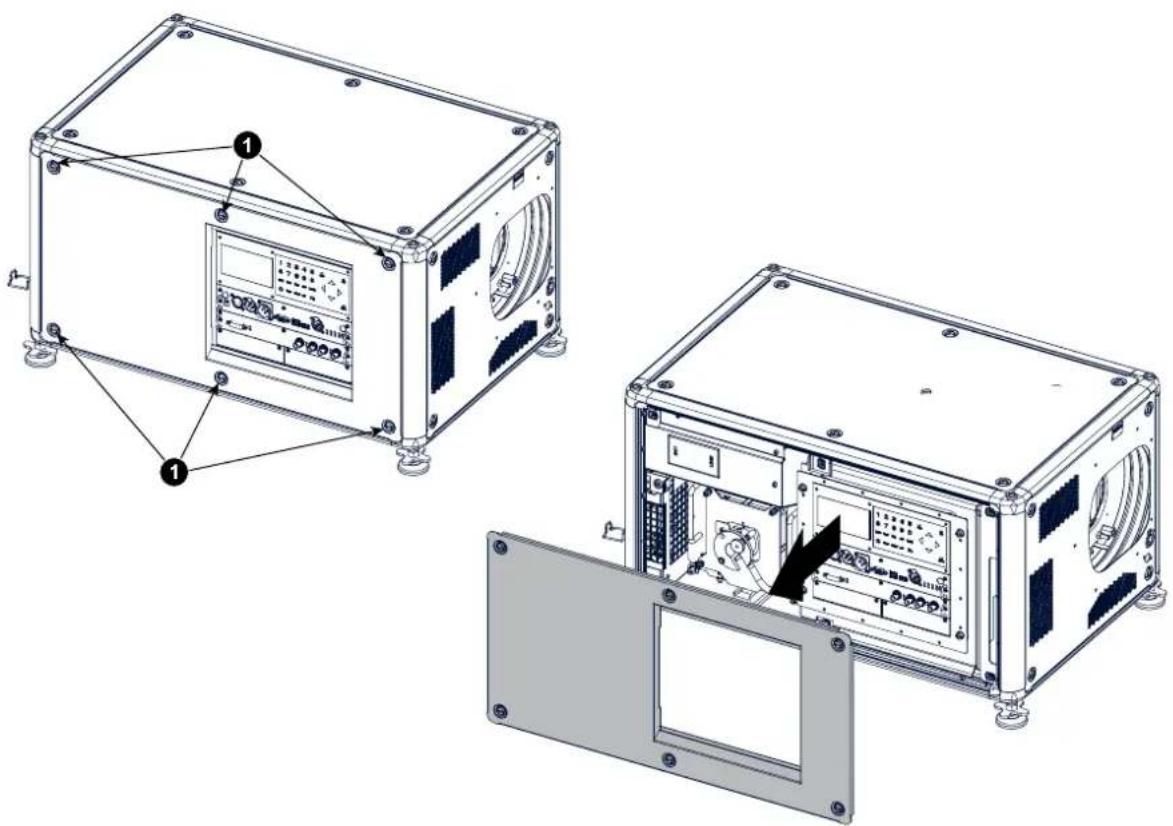
Image 13-8
Lamp side cover
2. Take off the side cover.
13.5Mountingthelampcover

WARNING: Switch off the projector and unplug the power cord before starting the procedure.
Necessarytools
7 m m flat screw driver
Howtomount
- Place the front cover on the is place and secure the 6 captive screws.
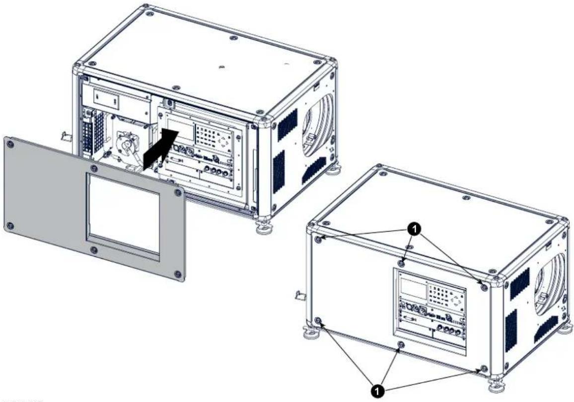
Image 13-9
Lamp side cover
13.6Removalofthelamphouse

WARNING: Switch off the projector and unplug the power cord before starting the procedure.
Necessarytools
Flat screwdriver
Howtoremove
- Remove the lamp cover on the input side, see "Removal of the lamp cover", page 79.
- Release the 3 spring lock screws.
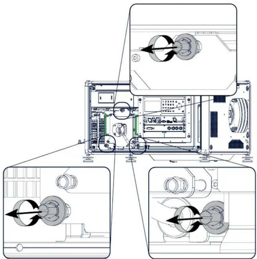
natural_image
Technical line drawing of a device internal structure with three views showing mechanical components and assembly (no text or symbols)Image 13-10 Lamp house, captive screws
- Take the lamp house by both handles and pull it out.
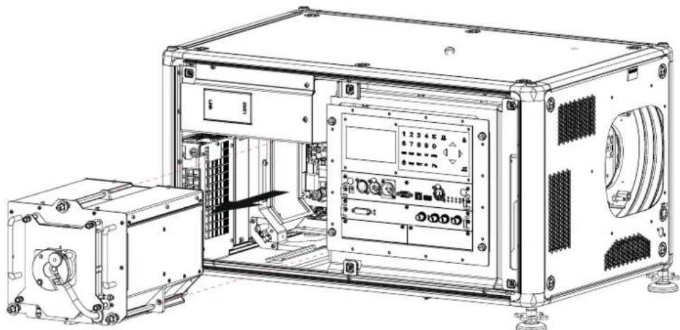
natural_image
Technical line drawing of an industrial control unit with internal components and a separate housing (no visible text or symbols)Image 13-11 Lamp house, removal
13.7 Installationofthelamphouse

WARNING: Switch off the projector and unplug the power cord before starting the procedure.
Necessarytools
Flat screwdriver
Howtoinstall
- Take the lamp house by its handles and gently slide the lamp house into its socket. Note that the compartment is provided with a guide (1) to position the lamp house correctly.
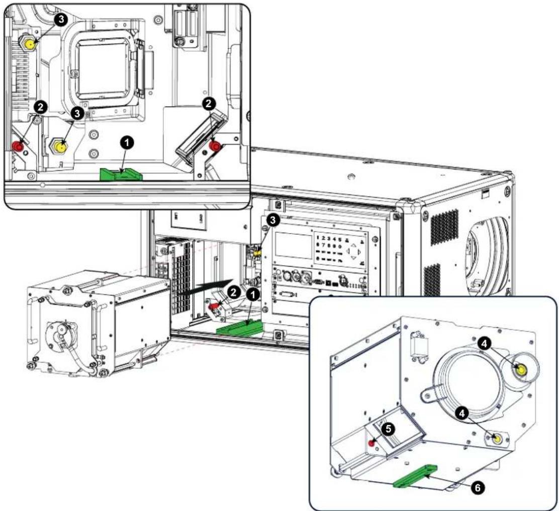
Image 13-12 Insert lamp house
-
Push the lamp house forward until it slides fully into the projector. Positioning pins (2) must match the holes (5) in the lamp house.
-
Secure this position by fastening the 3 spring lock screws.
-
Reinstall the lamp cover of the projector.

While starting up the projector, the electronics detect if a lamp is installed. If no lamp is installed, it is not possible to start the projector.
13.8 Replacement of the high density dust filter

CAUTION: The high density filter must be replaced on a regular basis, depending on the environment conditions of the projector.

WARNING: Switch off the projector and unplug the power cord before starting the procedure.
Necessaryparts
New filter (available kit : R98010085, contains 5 high density filters and one cleanable filter)
Howtoreplace
- Remove the front cover, see "Removal of the front cover", page 76.
- Push both filter holders to the outside.
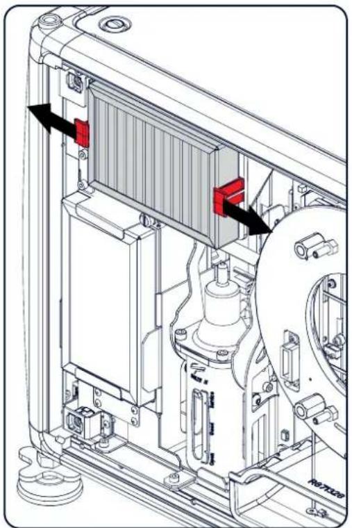
natural_image
Technical diagram of a mechanical assembly with labeled components and directional arrows (no readable text or symbols)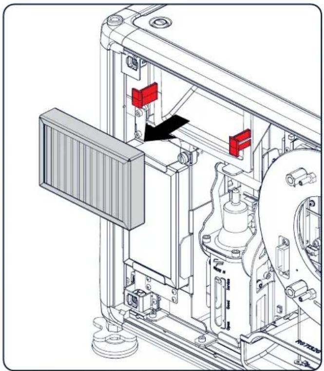
natural_image
Technical diagram of a mechanical assembly with red components and a black arrow indicating a specific component (no text or symbols present)Image 13-13
Filter replacement
- Take out the filter and insert a new one.

CAUTION: Never clean the filter Always replace with a new one.
13.9 Remove and clear metal front filter

WARNING: Switch off the projector and unplug the power cord before starting the procedure.
Necessaryparts
New filter when needed (available kit : R98010085, contains 5 HEPA filters and one cleanable filter)
Howtoremove
- Remove the front cover, see "Removal of the front cover", page 76.
-
Release the thumb screw (1)
-
Pull the bottom holder to the front.
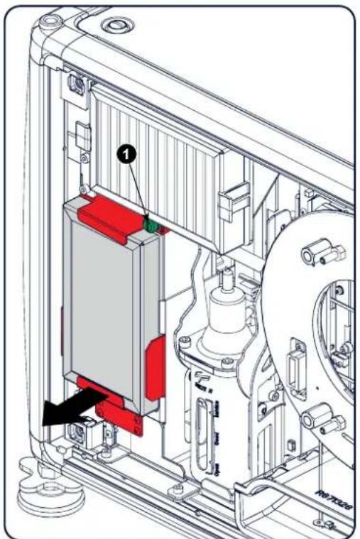
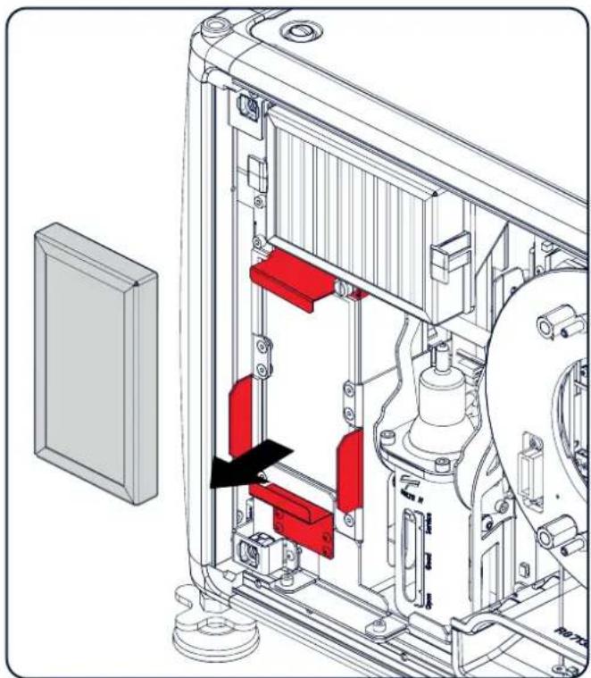
natural_image
Technical line drawing of a mechanical assembly with red components and a black arrow indicating a specific part (no text or symbols present)Image 13-14
4. At the same time, take out the filter.
Cleanthedustfilter
- Remove most contamination with a vacuum cleaner.
- Blow remaining dust away with compressed air in an other room or outside.

If you cannot clean the filter anymore, insert a new one.
Howtoinstall
- Pull the bottom holder to the front and insert the filter.
- Fasten the thumb screw (1).

CAUTION: Never use the projector with removed filters!
A.SPECIFICATIONS
Aboutthischapter
This chapter gives an overview of the specification of the HDX projector as well as the dimensions and the center of gravity.
Overview
• S p e c i fications of the HDX-4K20
- Dimensions of a HDX
• Technical Regulations
A.1SpecificationsoftheHDX-4K20
Specifications
| Projectortype | 4K UHD 3-Chip DLP digital projector |
| Technology | 0.90" DMD x 3 with sealed DMD core |
| Resolution | 3,840 x 2,400 (4K UHD) / 2,560 x 1,600 (WQXGA native) / 16:10 aspect ratio |
| Light Output | 19,000 (WQXGA) / 17,500 (4K UHD mode) center lumens* |
| Contrast ratio | 1,900:1 (standard) - 2,200:1 (high contrast mode) |
| Brightness uniformity | 90% |
| ScenergiX | horizontal and vertical edge blending** |
| Lens range | TLD+ 0.8-1.16; 1.16-1.5:1; 1.5-2.0:1; 2.0-2.8:1; 2.8-4.5:1; 4.5-7.5:1; 7.5-11.5:1 |
| Optical lens shift | Vertical: -30% to +120%/Horizontal: -40% to +40% on zoom lenses (memorized) |
| Colorcorrection | P7 |
| Lamps | 2.5 kW Xenon / lamp lifetime: 1,000 hours typical |
| Transportwithlamp | Yes |
| Lamphousequickreplace | Yes |
| Customerbulbreplace | Yes |
| Lampwarrantyfieldreplacefactoryreplace | 90 days, 500 hours/pro rata 750 hours |
| Optical dowser | Standard |
| Picture-in-picture | Two sources simultaneously** |
| Orientation | table - ceiling - side (portrait) (lamp door down/bottom) - vertical |
| DMX512 | Standard** |
| WARP | direct adjust OSD + toolset |
| integratedwebserver | Yes |
| CLOconstantlightoutput | standard** |
| 3D | active eyewear (optional), passive Infitec (optional), passive circular (optional), triple flash up to 200Hz** |
| Inputs | Dual HDBaseT, HDMI 2.0**, DP 1.2, Quad SDI/HDSDI/dual HDSDI/Quad 3G HDSDI/BarcoLink |
| Optionallnputs | Quad DP1.2 |
| InputResolutions | From VGA up to 4K (4,096 x 2,160) |
| maxpixelclock | 400 Mhz |
| Software tools | Projection Toolset + Android app** + iOS app** |
| Control | 10/100 Base-T, RJ-45 conn, Wifi ( opt), GSM (optional), XLR wired + IR , RS232, DMX 512** |
| ACpower | 110-130V/200-240V, 50-60 Hz |
| Powerconsumption | 3,000 W / STBY<8W |
| Noiseleveltypicalat25C77F53 dB (A) | |
| Operatingtemperature0 ~ 40°C / 32 | ~ 104°F |
| operationhumiditynocondens | 0% - 80% |
| DissipationBTU | Max. 5800 BTU/h @ (110-130V) / Max. 10,236 BTU/h @ (200-240V) |
| DimensionsWxLxH | 475 x 725 x 382 mm (18.70" x 28.54" x 14.96") |
| Weight | 50kg (110lbs) |
| Shipping Dimensions | (WxLxH) 650 x 900 x 560 mm (25.59" x 35.43" x 22.04") |
| Standard accessories | Power cord; wireless/XLR wired rugged remote control |
| Certifications | Compliant with UL60950-1 and EN60950-1, complies with FCC rules & regulations, part 15 Class A and CE EN55022 Class A, RoHS |
| Warranty3 years standard | |
| * | •*: +/- 10%•**: Available in future releases |
A.2 Dimensionsofa HDX
Overview
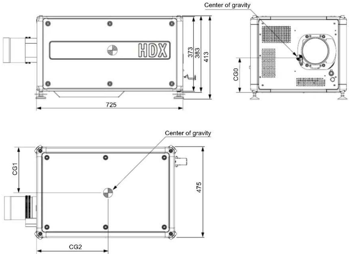
Image A-1
Dimensions, mm
| Geometrical centre | Centre without lens | Centre with lens | |
| CG0 | 186.5 | 170.0 | 185.0 |
| CG1 | 237.5 | 241.0 | 248.0 |
| CG2 | 362.5 | 370.0 | 330.0 |
A.3TechnicalRegulations
Certificates

Image A-2 EAC mark

Image A-3 Rohs
Image A-4 Rohs OK

Image A-5 CE mark

B.STACKINGHDXPROJECTORS
Overview
- Mount stacking points
- Stacking HDX projectors
• Aligning stacked HDX projectors
B.1Mountstackingpoints
Necessarytools
Allenkey8mm
Howtomount
- Place the first stacking point on a corner.
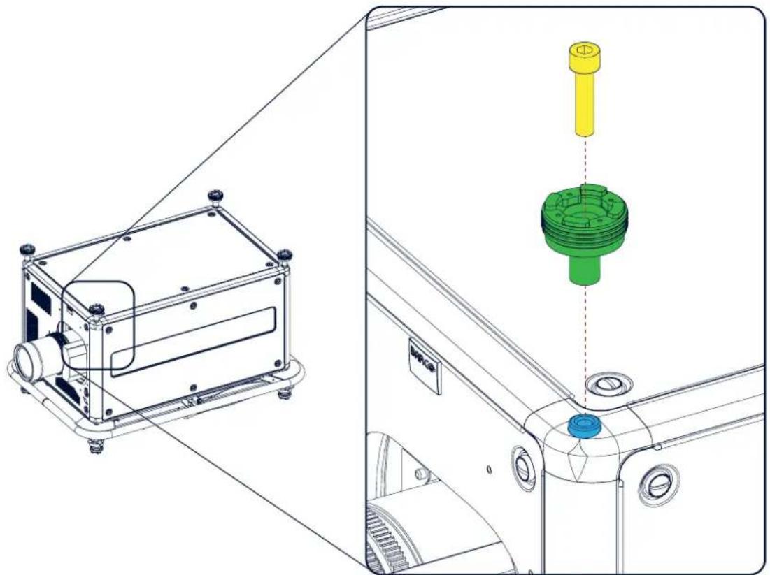
natural_image
Technical line drawing of a mechanical assembly with a green component inserted into a housing (no text or symbols)Image B-1
Stacking points, mount
2. Turn in the delivered bolt.
3. Repeat for the other 3 stacking points.
B.2StackingHDXprojectors

CAUTION: Maximum stack three (3) projectors in a table mounted configuration. Maximum stack two (2) projectors in a ceiling mounted configuration.
Howtostack
- Mount stacking points on lower projector. See "Mount stacking points", page 91.
- Mount a bottom carry handle on the upper projector. See "Mounting the bottom carry handler", page 22.
- Place the projector with carry handle on top of the projector with stacking points. Make sue that all interlocking pins match with their corresponding interlocking sockets.
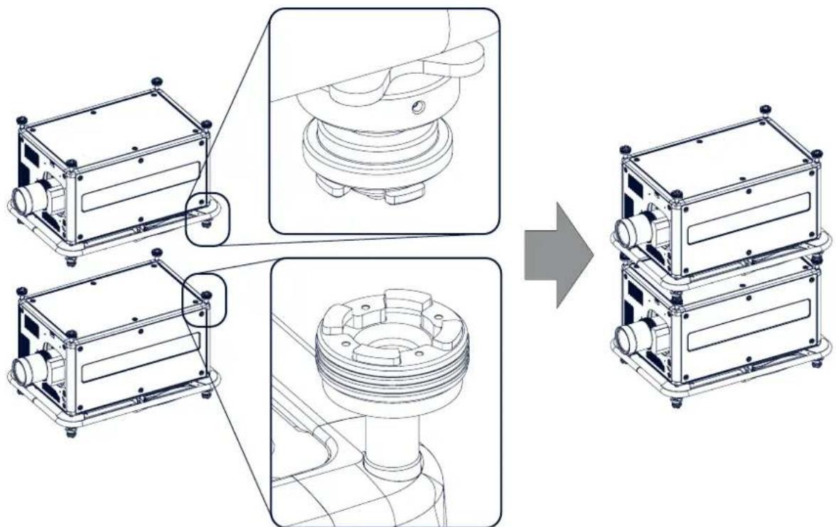
natural_image
Technical line drawing of a mechanical assembly process showing transformation from two identical components to three stacked ones (no text or symbols present)Image B-2 Dual stack
Tip: In case of stacking projectors for a ceiling mount configuration, first turn the projectors upside down before placing the projectorsontopofeachother.
4. Attach the two projectors together by closing all four interlocking adapters.
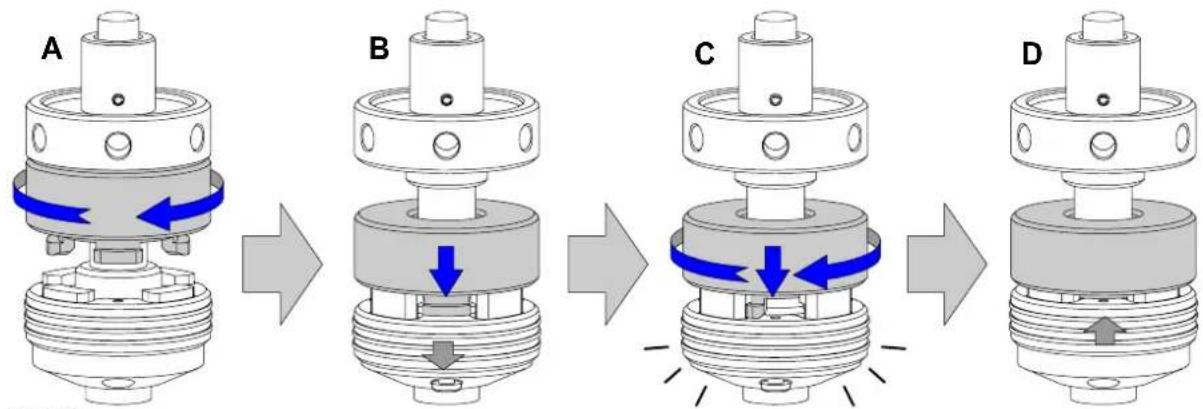
flowchart
graph LR
    A["Step A: Valve with inlet/outlet ports"] --> B["Step B: Actuator with blue directional arrows indicating movement"]
    B --> C["Step C: Actuator with blue directional arrows indicating movement"]
    C --> D["Step D: Actuator with inlet/outlet ports"]
Image B-3 Interlocking, close
Extraactionsforceilingmountedstack
Two safety cables must be mounted between both projectors, one at each longitudinal side.
- Mount the safety cable around the carrying handle of the bottom projector. Push the safety hook through the loop.
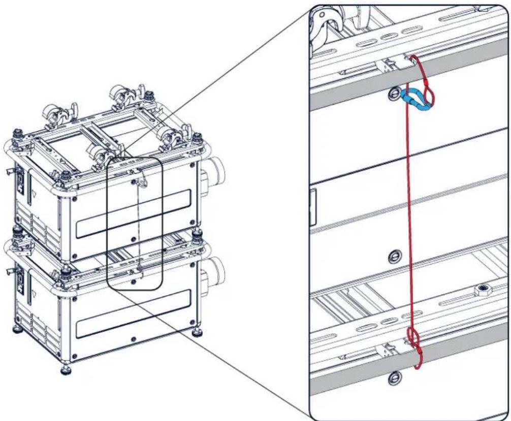
natural_image
Technical line drawing of a multi-tiered server rack with attached cable and wiring (no text or symbols)Image B-4
Security cables, mount
- Mount the other end of the security cable around the carry handle of the top projector and clasp the safety hook round the cable as illustrated.
Make sure that the falling distance is maximum 20 cm. If necessary, before clasping the safety hook around the cable, turn the cable a few time around the carry handle.
- Repeat this procedure for the second safety cable on the other side of the carry handle.

WARNING: Always use both safety cables of the lowest projector to secure a stacked projector in a ceiling mountconfiguration.
Howtoopenaninterlockingadapter
- Open an interlocking adaptor as illustrated.
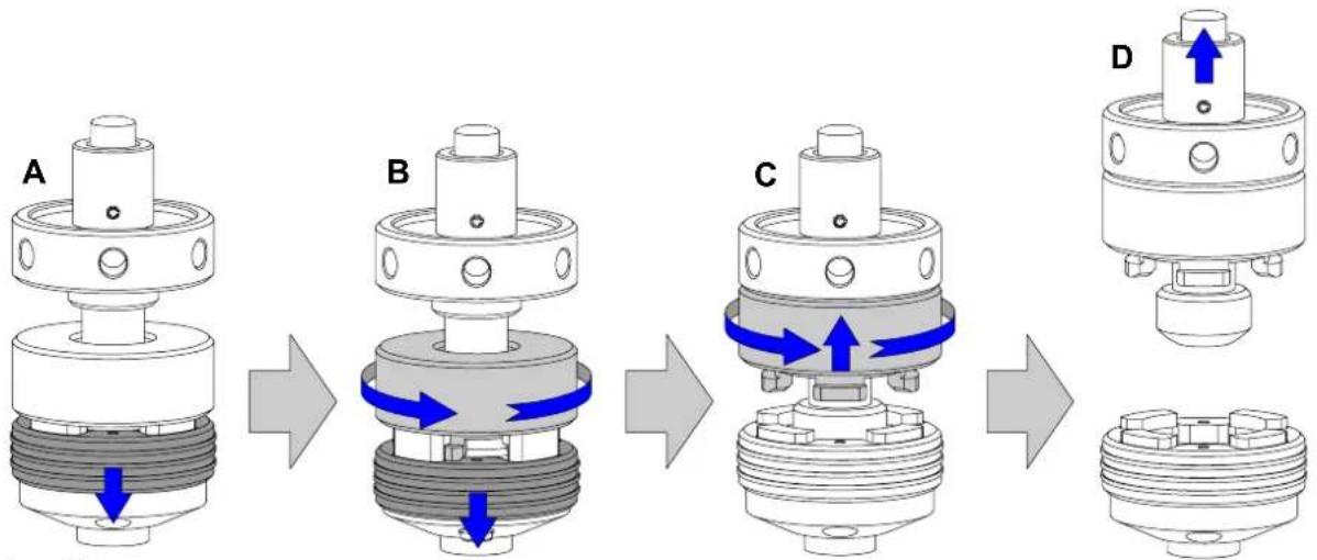
flowchart
graph TD
    A["Step A: Inlet and outlet"] --> B["Step B: Internal valve with blue directional arrows indicating motion"]
    B --> C["Step C: Internal valve with blue directional arrows indicating motion"]
    C --> D["Step D: Final actuator with blue upward arrow"]
Image B-5
Interlocking, open

WARNING: Never open an interlocking adapter of a stacked projector which is still suspended. First place the stacked projectorsonthefloor.
B.3AligningstackedHDXprojectors
Necessarytools
No tools.
Howtoalignstackedprojectors
- Make sure that the internal hatch pattern projected by the reference projector is sharp and has a perfect rectangle outline. If this is not the case, readjust the reference projector before aligning the other stacked projector(s) with the reference hatch pattern. Note: The reference projector in a stacked configuration is the lowest projector in case of table mount and the uppermost projectorincaseofceilingmount.
- Project with the stacked projector the same internal hatch pattern as the reference projector. Tip: Use a white colored hatch pattern for the reference projector and e.g. green colored for the stacked projector. This makesiteasiertoseethedifferencebetweenbothhatchpatternsprojected.
- If necessary, adjust the rotation of the stacked projector with respect to the reference projector by turning in or out the height adjustment ring of the interlocking adaptors at the rear of the stacked projector. Adjust until the outline of the hatch pattern is most symmetric with the reference hatch pattern.
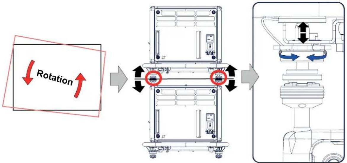
flowchart
graph LR
    A["Device 1"] -->|Rotation| B["Device 2"]
    B --> C["Device 3"]
    C --> D["Device 4"]
    style A fill:#f9f,stroke:#333
    style B fill:#ccf,stroke:#333
    style C fill:#cfc,stroke:#333
    style D fill:#fcc,stroke:#333
Image B-6 Stacked projectors, rotation
- If necessary, adjust the inclination of the stacked projector with respect to the reference projector by turning the height adjustment ring of the interlocking adaptor at the front of the stacked projector in or out. Adjust until the outline of the hatch pattern is most symmetric with the reference hatch pattern.
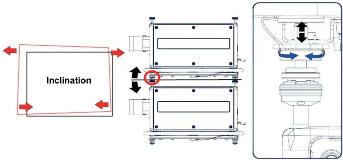
Image B-7 Stacked projectors, inclination
- If necessary, adjust the skew of the stacked projector with respect to the reference projector by turning the Hand screw in or out. The hand screw is located at smallest side of the carrying handle (front or back). Adjust until the outline of the hatch pattern is most symmetric with the reference hatch pattern.
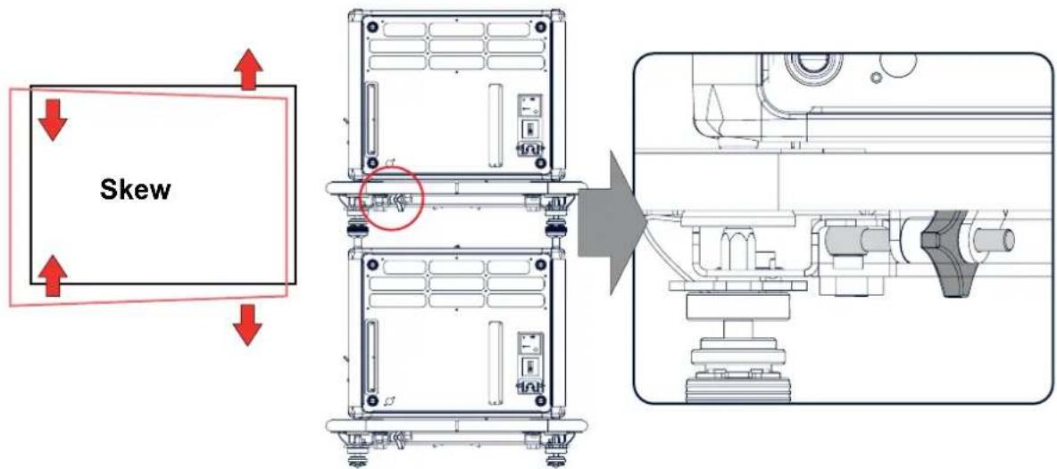
Image B-8 Stacked projectors, skew
- Shift the hatch pattern horizontally and vertically until the outline of the hatch pattern is most symmetrically placed with respect to the reference hatch pattern. Note: Note that the "Shift" function is motorized, which means that you have to access the projector software, via the local keypadremotecontrolunit,tooperatethe"Shift"function.
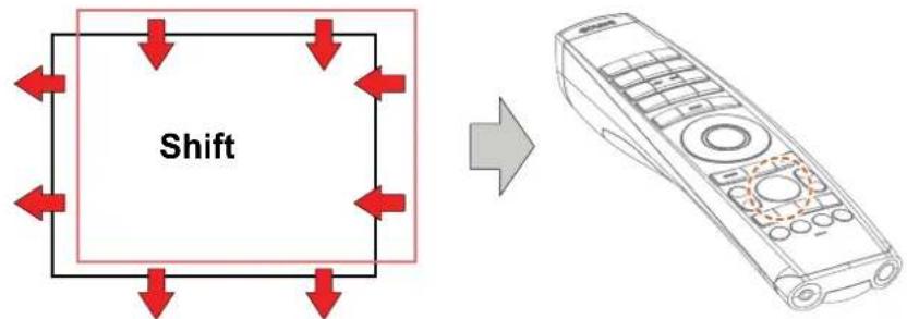
flowchart
graph TD
    A["Rectangular Box with Shift"] --> B["Remote Control"]
Image B-9
- Zoom the hatch pattern in or out until the outline of the hatch pattern matches exactly the outline of the reference hatch pattern. Note: Note that the "Zoom" function is motorized, which means that you have to access the projector software, via the local keypadremotecontrolunit, to operate the "Zoom" function.
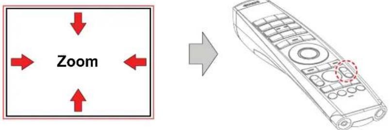
Image B-10
8. If necessary, repeat from step 2 until the hatch pattern of the stacked projector is perfectly aligned with the hatch pattern of the reference projector.

In case of a triple stacked table mount projector configuration adjust and align first the bottommost projector (reference), than the projector in the middle and finally the uppermost projector.
C.ENVIRONMENTALINFORMATION
Overview
- Disposal information
• Turkey RoHS compliance - Contact information
C.1 Disposal information
DisposalInformation
Waste Electrical and Electronic Equipment

This symbol on the product indicates that, under the European Directive 2012/19/EU governing waste from electrical and electronic equipment, this product must not be disposed of with other municipal waste. Please dispose of your waste equipment by handing it over to a designated collection point for the recycling of waste electrical and electronic equipment. To prevent possible harm to the environment or human health from uncontrolled waste disposal, please separate these items from other types of waste and recycle them responsibly to promote the sustainable reuse of material resources.
For more information about recycling of this product, please contact your local city office or your municipal waste disposal service.
For details, please visit the Barco website at: http://www.barco.com/en/AboutBarco/weee
Disposalofbatteriesintheproduct

This product contains batteries covered by the Directive 2006/66/EC which must be collected and disposed of separately from municipal waste.
If the battery contains more than the specified values of lead (Pb), mercury (Hg) or cadmium (Cd), these chemical symbols will appear below the crossed-out wheeled bin symbol.
By participating in separate collection of batteries, you will help to ensure proper disposal and to prevent potential negative effects on the environment and human health.
Disposaloflamp
Dispose of expired bulbs that are beyond warranty in the following manner: wrap the bulb tightly in several layers of canvas or heavy cloth. Place it on hard surface and shatter the envelope with a sharp hammer blow. DO NOT place a non shattered bulb in any ordinary refuse container.
Small amounts of radioactive material (< 1000 Bq per lamp) are deliberately added to Xenon lamps for functional reasons. These lamps are manufactured under regulatory control as consumer product according to IAEA basic safety standard BSS 115. Disposal according to national regulations is required e.g. in Europe covered by WEEE regulation. See also related user manual of the lamp supplier for more guidance.
C.2 Turkey RoHS compliance
TurkeyRoHScompliance

[Republic of Turkey: In conformity with the WEEE Regulation]
C.3Contactinformation
Barcocontactinformation
President Kennedypark 35, 8500 Kortrijk, Belgium
Importerscontactinformation
To find your local importer, contact Barco directly or one of Barco's regional offices via the contact information given on Barco's web site, www.barco.com.
Madeininformation
The made in country is indicated on the product ID label on the product itself.
Productiondate
The month and year of production is indicated on the product ID label on the product itself.
GLOSSARY
DefaultGateway
A router that serves as an entry point into and exit point out of a network. For example, a local network (LAN) may need a gateway to connect it to a wide area network (WAN) or to the Internet.
DHCP
Dynamic host configuration protocol. DHCP is a communications protocol that lets network administrators manage centrally and automate the assignment of IP addresses in an organization's network. Using the Internet Protocol, each machine that can connect to the Internet needs a unique IP address. When an organization sets up its computer users with a connection to the Internet, an IP address must be assigned to each machine. Without DHCP, the IP address must be entered manually at each computer and, if computers move to another location in another part of the network, a new IP address must be entered. DHCP lets a network administrator supervise and distribute IP addresses from a central point and automatically sends a new IP address when a computer is plugged into a different place in the network.
DMX
DMX-512 Lighting protocol over RS-485 interface. Carries information of 512 channels from a lighting controller to lighting devices. Standardized by USITT.
HD
Hazard Distance (HD) is the distance measured from the projection lens at which the intensity or the energy per surface unit becomes lower than the applicable exposure limit on the cornea or on the skin. The light beam is considered (to be) unsafe for exposure if the distance from a person to the light source is less than the HD.
-8
IP
Internet Protocol. The network layer of TCP/IP. Required for communication with the internet.
Lightprocessorunit
Heart of the projector, unit inside this projector which is responsible for the creation of the image to be projected on the screen. Also called 'engine'.
MACaddress
Media Access Control address. Unique hardware number, used in combination with the IP-address to connect to the network (LAN or WAN).
RS232
An Electronic Industries Association (EIA) serial digital interface standard specifying the characteristics of the communication path between two devices using either D-SUB 9 pins or D-SUB 25 pins connectors. This standard is used for relatively short-range communications and does not specify balanced control lines. RS-232 is a serial control standard with a set number of conductors, data rate, word length and type of connector to be used. The standard specifies component connection standards with regard to computer interface. It is also called RS-232-C, which is the third version of the RS-232 standard, and is functionally identical to the CCITT V.24 standard. Logical '0' is > + 3V, Logical '1' is < - 3V. The range between -3V and +3V is the transition zone.
RS422
An EIA serial digital interface standard that specifies the electrical characteristics of balanced (differential) voltage, digital interface circuits. This standard is usable over longer distances than RS-232. This signal governs the asynchronous transmission of computer data at speeds of up to 920,000 bits per second. It is also used as the serial port standard for Macintosh computers. When the difference between the 2 lines is < - 0.2V that equals with a logical '0'. When the difference is > +0.2V that equals to a logical '1'.
Scheimpflugprinciple
The "plane of sharp focus" can be changed so that any plane can be brought into sharp focus. When the DMD plane and lens plane are parallel, the plane of sharp focus will also be parallel to these two planes. If, however, the lens plane is tilted with respect to the DMD plane, the plane of sharp focus will also be tilted according to geometrical and optical properties. The DMD plane, the principal lens plane and the sharp focus plane will intersect in a line below the projector for downward lens tilt.
Subnetmask
A number that is used to identify a subnetwork so that IP addresses can be shared on a local area network.
TR(ThrowRatio)
The ratio of the distance to the screen (throw) to the screen width.
INDEX
A
Air flow 18
Air inlets 18
Air outlets 18
Alignment 22, 27, 63–64
Ceiling mounted projector 27
Table mounted projector 22
Warping 63–64
4 Corners 64
Screen Size 63
B
Bottom carry handler 22
Brightness 57
C
Carry handler 22, 24
Bottom 22
Top 24
Cleaning 73
Exterior 73
Ler
Communication 41–44
DMX 43
Ethernet 42
Introduction 41
RS232 43
RS422 43
USB port 44
Communication panel 43
Configurations 15
Front projection 15
Rear projection 15
Connection 21
Power cable 21
Power net 21
Contrast 57
Cooling liquid circuit warning 5
Cooling requirements 11
D
Dimensions 88
Projector 88
DMX input 43
DMX interface 43
DMX out 43
Download plug-in 18
Download Projector Toolset 18
Dust filter 84
Clean 84
Remove 84
Dust filter, high density 83
Replace 83
E
Enclosed projection 8
Environment conditions 11
Environmental information 97
Disposal information 97
RoHS compliance 97
Turkey 97
Environmental Information 97
Ethernet 42
Ethernet connection 67–68
IP address, wired connection 68
Exterior 73
Cleaning 73
F
Flight case 14
Focus zoom 61
Front cover 76, 78
Mount 78
Removal 76
Front projection 15
Fuses 22
G
General 18
Download plug-in 18
Download Projector Toolset 18
General considerations 3
Getting started 47
Terminology overview 47
Getting Started 47
Graphic User Interface 53
Overview 53
GUI 53–54, 57, 61
Image 57
Installation 61
Navigation 53
Overview 53
Test Patterns 54
H
Hang up 25
Projector 25
Hazard Distance 7–8
HD 9
Throw Ratio (TR) 9
High Brightness precautions 7
Horizontal tilt range 17
How to use 50
RCU 50
Remote control 50
|
Illumination 65
Importer 98
Initial inspection 13
Box content 13
Input 41, 75
Insertion 75
Introduction 41
Source 41
Insert 75
Input module 75
Install 82
Lamp house 82
Installation 14, 31
Lens 31
Projector configurations 14
Installation preparations 11
Installation requirements 11–12
Clean air 11
Environment conditions 11
Power requirements 12
Projector weight 12
L
Lamp cover 79–80
Mount 80
Removal 79
Lamp house 81–82
Installation 82
Remove 81
Lens 29, 31, 33, 35, 70, 73
Adjustment 70
Calibration 70
Available 29
Cleaning 73
Installation 31
Removal 33
Safety cable 33
Scheimpflug 35
Lens adjustment 70
Calibration 70
Lens installation 31
Lens removal 33
Lens selection 30
Lens shift 61
Lenses 29–30
Lens selection 30
Local keypad 47
Functionality overview 47
M
Maintenance 73
Mechanical check 14
Mount 78, 80, 91
Front cover 78
Lamp cover 80
Stacking points 91
N
Network 67
Introduction 67
Network connection 67–68
IP address, wired connection 68
Notice on safety 4
0
Off axis 16
On axis 16
Orientation 62
Orientations 15
Front projection 15
Rear projection 15
Output resolution 59
P
P7 58
Realcolor 58
Physical Installation 21
Positioning 16
Power cable 21
Connection 21
power net 21
Connection 21
Power off 50
Power on 48
Power requirements 12
Prevent 4
Electrical shock 4
Projector 16–17
Positioning 16
Shift range 17
Projector configurations 14–15
Front projection 15
Rear projection 15
Projector control 67
Network 67
Introduction 67
Projector weight 12
R
RCU 47, 50
Functionality overview 47
How to use 50
Rear projection 8, 15
Remote control 50
How to use 50
Removal 33, 76, 79
Front cover 76
Lamp cover 79
Lens 33
Remove 81, 84
Dust filter 84
Lamp house 81
Replace 83
Dust filter, high density 83
Reset 71
All 71
Features 71
Image 71
Motor 71
Optics 71
Orientation 71
Other 71
User Interface 71
Warping 71
Rigging clamps 25
Rigging points 25
RS232 43
RS422 43
S
Safety 3–8, 10
Battery explosion 6
Cooling liquid circuit 5
Electrical shock 4
Fire hazard 5
Flight cases 10
Hazard Distance 7–8
Important instructions 4
Personal injury 4
Projector damage 5
Servicing 6
Safety cable 33
Lens 33
Saturation 57
Scheimpflug 35
Serial communication 43
Servicing 75
Shift range 17
Source 41, 55
Connector Settings 55
Input 41
Specifications 87
HDX-4K20 87
Stacking 91, 94
Mount stacking points 91
Projectors 91, 94
Align 94
Stacking points 91
Mount 91
Standby 50
Switch to 50
Status Light 44
Suspend 25
Projector 25
Suspension 25
With rigging clamps 25
Switching off 50
Switching on 48
Switching to standby 50
System Settings 67–71
Communication 67–68
IP address, wired connection 68
Lens adjustment 70
Calibration 70
Network 67
Reset 71
Service 69–70
Color 69
Statistics 70
T
Table mounted projector 22
Alignment 22
Technical Regulations 89
Test Patterns 54
Themes 68
Tilt range 17
Horizontal 17
Vertical 17
Top carry handler 24
U
Unpacking 12
Projector 12
USB port 44
User definition 4
V
Vertical tilt range 17
W
Warnings 5
Cooling liquid circuit 5
Warping 63

- Productrevision
- Copyright©
- Changes
- Trademarks
- GuaranteeandCompensation
- FederalCommunicationsCommission(FCCStatement)
- EN55022/CISPR22ClassAITE(InformationTechnologyEquipment)
- TABLEOFCONTENTS
- Safety....3
- Installation preparations .... 11
- Physical Installation ......21
- Lenses & Lens selection....29
- Input & Communication....41
- Getting Started....47
- GraphicUserInterface (GUI)....53
- GUI – Source ....55
- GUI - Image ....57
- GUI – Installation ...... 61
- GUI-System Settings....67
- Maintenance....73
- Servicing....75
- Specifications 87
- Stacking HDX projectors....91
- Environmental Information ......97
- Glossary 99
- Index....101
- 1.SAFETY
- Aboutthischapter
- Clarificationoftheterm“HDX”usedinthisdocument
- General considerations
- Generalsafetyinstructions
- Noticeonsafety
- Usersdefinition
- Important safety instructions
- Topreventtheriskofelectricalshock
- Topreventpersonalinjury
- Topreventfirehazard
- Topreventprojectordamage
- Onservicing
- Topreventbatteryexplosion
- High Brightness precautions: Hazard Distance (HD)
- RestrictionZone(RZ)basedontheHD
- Safety
- 1.4HDforfullyenclosedprojectionsystems
- HD
- 1.5HDinfunctionofthelensThrowRatio(TR)
- TR(ThrowRatio)
- Important warnings concerning HDXflight cases
- Important warnings concerning stacking/transporting HDX rental flight cases
- 2.INSTALLATIONPREPARATIONS
- Overview
- Installationrequirements
- Environmentconditions
- Coolingrequirements
- Cleanairenvironment
- MainPowerrequirements
- Projectorweight
- Unpacking the projector
- Whathastobedone?
- Necessarytools
- Howtounpack
- Initial inspection
- General
- Boxcontent
- Mechanicalcheck
- 2.4HDXflightcase
- IntroductionoftheHDXflightcase
- 2.5Projectorconfigurations
- Thedifferentconfigurations
- Frontprojection
- Rearprojection
- Onaxis/offaxisprojection
- Shiftrange
- Horizontalandverticalprojectortiltranges
- 2.6Projectorairinletsandoutlets
- 2.7FreedownloadofProjectorToolset
- AboutProjectorToolset
- Where to find the download file(s)
- Installation
- 3.PHYSICALINSTALLATION
- Connecting the projector with the powernet
- Howtoconnectwithlocalpowernet
- Fuses
- Alignmentofatablemountedprojector
- Howtoalign
- 3.3Mountingthebottomcarryhandler
- Necessaryparts
- Howtomount
- 3.4Mountingthetopcarryhandler
- Purpose
- Suspension of the projector with rigging clamps
- Riggingpointsandriggingclamps
- Howtoinstallandusetheriggingclamps
- Physical Installation
- Alignment of faceiling mounted projector
- Skewadjustment
- Tiltadjustmentwiththeclamps
- 4.LENSSES&LENSSELECTION
- Availablelenses
- Limitedamountofavailablelenses
- AvailablelensesfortheHDXprojector
- Lensselection
- Howtoselecttherightlens
- Lens installation
- Howtoinstall
- Lensremoval
- Howtoremove
- Lenssafetycable
- Whenusingthesafetycable?
- Howtomountthecable
- Scheimpflugadjustment
- Scheimpflugprinciple
- IndicationondrawingFunction
- Howtoadjust
- How to fix the Scheimpflug
- INPUT&COMMUNICATION
- Introduction
- Input source connections
- Inputspecifications
- • 3GSDI
- - DisplayPort
- Ethernetport
- Virtual&AugmentedRealityInput(V&AR)(Optional)
- Communication connections
- 12Voutput
- DMXinterface
- DMX
- RS232/RS422input
- RS232
- RS422
- USBport
- LEDandButtonindicationchart
- LEDStatus
- 6.GETTINGSTARTED
- Howcontrollingtheprojector?
- Locationofthelocalkeypad?
- Remotecontrolfunctions.
- Functionalityoverview
- LocalKeypadoverview
- Poweronprojector
- Howtopoweron.
- Statusoverview
- Startingimageprojection
- Switching to stand by
- Howtoswitchtostandby
- Poweroffprojector
- Howtopoweroff
- 6.5UsingtheRCU
- Pointingtothereflectivescreen
- HardwiredtotheXLRinput
- PointingdirectlytothelRsensor
- GRAPHICUSERINTERFACE(GUI)
- 7.1Overview
- 7.2Navigation
- 7.3TestPatterns
- Howtousetestpatterns
- GUI-SOURCE
- SourceSelection
- Howtoselect?
- Connector Settings
- Howtoconfiguretheconnector
- Image 8-5
- GUI-IMAGE
- Settingimagelevelsmanually
- HowtosetupContrast
- HowtosetupBrightnessLevel
- HowtosetupSaturationLevel
- 9.2P7Realcolor
- HowtosettheP7desiredvalu es
- Settingtheoutputresolution
- Howtochooseoutputresolution
- GUI-INSTALLATION
- Overview of features
- 10.1Configuringthelens
- Whatcanbedone?
- Howtoconfigurethelens
- 10.2Orientation
- Howtosetthecorrectorientation
- 10.3Warping
- Aboutwarping
- Warping-ScreenSize
- AboutScreenSizeadjustment
- Howtoadjusttheimage?
- Warping-4cornersadjustment
- About4Cornersadjustment
- Lampillumination
- Howtoreducethepower
- GUI-SYSTEM SETTINGS
- Communication
- Aboutanetworkconnection
- Introduction to a Network connection
- DHCP
- IP
- Subnetmask
- DefaultGateway
- MACaddress
- WhatshouldbesetupforanEthernetaddress?
- WiredIPaddresssetup
- HowtomanuallysetupthelPaddress
- Themes
- Howtoselectadifferentinterfacet heme
- Light, Dark
- 11.3ServiceMenu
- Service-Color
- Howtoadjust the P7nativesettings
- Service-Statistics
- Whatcanbeseen?
- Howtodisplaytheststatistics
- Lens Calibration
- Howtocalibrate
- 11.4Reset
- Howtoresetoneormoreprojectorsettings
- Howtoresetallprojectorsettings
- 12.MAINTENANCE
- Cleaningthelens
- Howtocleanthelens?
- Cleaningtheexterioroftheprojector
- Howtocleantheexterioroftheprojector?
- 13.SERVICING
- Removal of the front cover
- 13.3Mountingthefrontcover
- 13.4Removalofthelampcover
- 13.5Mountingthelampcover
- 13.6Removalofthelamphouse
- Installationofthelamphouse
- Replacement of the high density dust filter
- Howtoreplace
- Remove and clear metal front filter
- Cleanthedustfilter
- A.SPECIFICATIONS
- A.1SpecificationsoftheHDX-4K20
- A.2 Dimensionsofa HDX
- A.3TechnicalRegulations
- B.STACKINGHDXPROJECTORS
- B.1Mountstackingpoints
- B.2StackingHDXprojectors
- Howtostack
- Extraactionsforceilingmountedstack
- Howtoopenaninterlockingadapter
- B.3AligningstackedHDXprojectors
- Howtoalignstackedprojectors
- C.ENVIRONMENTALINFORMATION
- C.1 Disposal information
- DisposalInformation
- Disposalofbatteriesintheproduct
- Disposaloflamp
- C.2 Turkey RoHS compliance
- TurkeyRoHScompliance
- C.3Contactinformation
- Barcocontactinformation
- Importerscontactinformation
- Madeininformation
- Productiondate
- GLOSSARY
- Lightprocessorunit
- INDEX
- A
- B
- C
- D
- E
- F
- G
- H
- |
- L
- M
- N
- 0
- P
- R
- S
- T
- U
- V
- W
Brand : Barco
Model : HDX-4K12
Category : Projector