
Balder - Projector Barco - Free user manual and instructions
Find the device manual for free Balder Barco in PDF.


| Product Type | Video Projector |
| Brand | Barco |
| Model | Balder |
| Display Technology | 3-chip DLP |
| Native Resolution | 3840x2160 (4K UHD) |
| Light Source | Laser Phosphor |
| Brightness (Typical) | 3500 lumens |
| Contrast Ratio | 5400:1 |
| Lens Shift | Motorized, vertical and horizontal |
| Warping | 4 corners and bow adjustment |
| Edge Blending | Yes, with Black level and RGB gain adjustment |
| 3D Support | Active Stereo and Passive Stereo |
| HDR Support | Yes, HDR10, PQ |
| Video Inputs | HDMI, DisplayPort, HDBaseT, SDI |
| Network Connectivity | Ethernet, Wi-Fi, HDBaseT LAN |
| Control | DMX, PJLink, IR, RS232 |
| Software Platform | Pulse OSD (version 2.6) |
| Weight (Approx.) | 28 kg |
| Dimensions (W x D x H, Approx.) | 590 x 480 x 240 mm |
Frequently Asked Questions - Balder Barco
User questions about Balder Barco
0 question about this device. Answer the ones you know or ask your own.
Ask a new question about this device
Download the instructions for your Projector in PDF format for free! Find your manual Balder - Barco and take your electronic device back in hand. On this page are published all the documents necessary for the use of your device. Balder by Barco.
USER MANUAL Balder Barco
User Guide
Product revision
Software Revision: Pulse 2.6
Copyright ©
All rights reserved. No part of this document may be copied, reproduced or translated. It shall not otherwise recorded, transmitted or stored in a retrieval system without the prior written consent of Barco.
Trademarks
Brand and product names mentioned in this manual may be trademarks, registered trademarks or copyrights of their respective holders. All brand and product names mentioned in this manual serve as comments or examples and are not to be understood as advertising for the products or their manufacturers.
Changes
Barco provides this manual 'as is' without warranty of any kind, either expressed or implied, including but not limited to the implied warranties or merchantability and fitness for a particular purpose. Barco may make improvements and/or changes to the product(s) and/or the program(s) described in this publication at any time without notice.
This publication could contain technical inaccuracies or typographical errors. Changes are periodically made to the information in this publication; these changes are incorporated in new editions of this publication.
The latest edition of Barco manuals can be downloaded from the Barco website https://www.barco.com.
Patent protection
Please refer to https://www.barco.com/about-barco/legal/patents.
Product Security Incident Response
As a global technology leader, Barco is committed to deliver secure solutions and services to our customer while protecting Barco's intellectual property. When product security concerns are received, the product security incident response process will be triggered immediately. To address specific security concerns or to report security issues with Barco products, please inform us via contact details mentioned on https://www.barco.com/psirt. To protect our customers, Barco does not publicly disclose or confirm security vulnerabilities until Barco has conducted an analysis of the product and issued fixes and/or mitigations.
Disclaimer on screenshot images used in this manual
The screenshot images used in this manual are example illustrations and should be treated as such. While name of the product displayed in the images may be different from the product model currently used, the menu lay-out and functionality is identical.
Software License Agreement
Carefully read the following terms and conditions before using this software. Any use of this software indicates the acceptance of this license agreement and warranty.
Terms and Conditions:
- No redistribution of the software is allowed.
- Reverse-Engineering. This software product may not be reverse engineered, decompiled, disassembled or altered.
Disclaimer of Warranty:
This software and the accompanying files are sold “as is” and without warranties as to performance or merchantability or any other warranties whether expressed or implied. In no event shall Barco be liable for damage of any kind, loss of data, loss of profits, business interruption or other pecuniary loss arising directly indirectly. Any liability of the seller will be exclusively limited to replacement of the product or refund of purchase price.
Table of contents
1 General 9
1.1 Introduction....10
1.2 First start of the software 11
1.3 Using the UI elements....13
1.4 Dashboard screens.... 15
1.5 Navigation 17
2 Projector configuration process overview....19
2.1 Prerequisites....20
2.2 Process overview....21
3 User rights and logging in....23
3.1 User accounts and security....24
3.2 User authentication....26
4 Source 29
4.1 Displaying a single source 30
4.2 Displaying multiple sources: Stitched layouts....32
4.3 Connector settings 35
4.4 Configure override....37
4.5 No source image 39
5 Image 41
5.1 Adjusting contrast 42
5.2 Adjusting brightness....43
5.3 Adjusting the saturation....44
5.4 Adjusting the sharpness....45
5.5 Adjusting the gamma correction....47
5.6 Setting the desired gamma type....48
5.7 Tilted brightness uniformity correction 50
5.8 Digital zoom and shift 53
5.9 Cinemascope – Cropping the image....56
5.9.1 Introduction to Cinemascope and image cropping....56
5.9.2 Image cropping – auto cropping .... 57
5.9.3 Image cropping – using aspect ratio presets....58
5.9.4 Image cropping – manual cropping .... 59
5.10 Advanced image setting....61
5.10.1 RealColor P7 - Custom P7 settings 61
5.10.2 RealColor P7 - Presets 62
5.10.3 Setting the output resolution....63
5.10.4 Displaying HDR content....64
5.10.5 Dynamic contrast 66
5.10.6 BrilliantColor ™ 67
5.10.7 Smear reduction 68
5.10.8 Cropping the image to 16:9 centered 69
5.10.9 Night vision....70
6 Installation 73
6.1 Configuring the projector position....74
6.1.1 Orientation 74
6.1.2 Laser ranging 75
6.1.3 Tilt sensor....77
6.1.4 Manipulating the rigging frame, center position....78
6.1.5 Manipulating the motorized rigging frame 79
6.2 Configuring optics....82
6.2.1 Optical zoom and focus 82
6.2.2 Configuring lens shift 82
6.2.3 Configuring dynamic focus on UST lens 83
6.2.4 Shift to center 87
6.2.5 Configuring the Iris 88
6.2.6 Shutter mode 89
6.3 Scaling modes 91
6.4 Warping 93
6.4.1 Warping-on/off....93
6.4.2 Warping – Screen size 93
6.4.3 Warping - 4 corners adjustment....96
6.4.4 Warping-Bow 98
6.4.5 Warping – Warp files 103
6.4.6 Warping – Latency control in a multi projector setup 104
6.5 Blending & masking....107
6.5.1 Basic blend 108
6.5.2 Blend mask....109
6.5.3 Blend files....112
6.5.4 Black level adjustment 113
6.5.5 RGB gain adjustment....115
6.5.6 Black level files....116
6.6 Illumination 119
6.7 IR illumination – Night vision functionality 121
6.8 3D projection 124
6.8.1 About Active Stereo & Passive Stereo.... 124
6.8.2 Image Generators and IG pixel shift....125
6.8.3 Setup process 3D projection 125
6.8.4 Connection possibilities....125
6.8.5 3D Setup 126
7 Projector profiles 129
7.1 Profiles introduction.... 130
7.2 Saving the current projector settings in a profile 132
7.3 Assigning a projector profile to a preset.... 134
7.4 Deleting a projector profile....136
8 Settings 139
8.1 Product registration.... 140
8.1.1 About product registration....140
8.1.2 Product registration workflow 141
8.1.3 Product registration for Pulse OSD using the Barco Pulse Mobile app......
8.1.4 Manual product registration.... 142
8.2 Communication....147
8.2.1 Remote control 147
8.2.1.1 Remote control – Broadcast address 147
8.2.1.2 Remote control – Projector address.... 147
8.2.1.3 Remote control – IR sensors 148
8.2.2 Host name - Custom projector name setup 149
8.2.3 Network setup 150
8.2.3.1 Introduction to a Network connection 150
8.2.3.2 Wired IP address – Automatic setup....152
8.2.3.3 Wired IP address set up – Manual setup....152
8.2.3.4 Wi-Fi IP address – Automatic setup 153
8.2.3.5 Wi-Fi IP address – Manual setup 155
8.2.3.6 LAN over HDBaseT ^TM IP address - Automatic setup 19
8.2.3.7 LAN over HDBaseT ^TM IP address – Manual setup.... 15
8.2.4 DMX 159
8.2.5 PJLink 161
8.2.6 GSM configuration....164
8.2.7 Trigger outputs control 165
8.3 User interface 167
8.3.1 Changing the User Interface language....167
8.3.2 Themes 167
8.3.3 Units (measurement) system setup....168
8.3.4 Controlling the backlight of the LCD Display 169
8.4 Date and time 171
8.4.1 Date and time setup - automatically 171
8.4.2 Date and time setup - manually 173
8.5 Scheduler 175
8.5.1 About the projector scheduler....175
8.5.2 Adding a new command in the scheduler 175
8.5.3 Edit or Delete a command....178
8.5.4 Clearing the scheduler 178
8.6 Power settings 180
8.6.1 Auto dimming 180
8.6.2 Auto light source off 180
8.6.3 Auto standby....181
8.6.4 Controlling the front XLR connector 182
8.7 System 185
8.7.1 Setting up the external cooler 185
8.7.2 Operational mode 185
8.7.3 Capture mode 187
8.8 Lens features 189
8.9 Maintenance....190
8.9.1 Factory reset.... 190
8.9.2 Lens calibration....194
8.9.3 Flex brightness 195
8.9.4 Flex resolution 197
8.9.5 Rigging frame Calibration....199
8.9.6 Electronic convergence 200
8.10 Advanced settings 203
8.10.1 Security 203
8.10.1.1 Security – Enable source preview 203
8.10.1.2 Security – Enable camera preview.... 204
8.10.1.3 Security – Enable custom test pattern upload ......
8.10.2 Service – RealColor calibration.... 206
8.10.3 Service – Color wheel....207
8.10.4 Service – Statistics....208
8.10.5 Advanced settings – Laser pulsing calibration 209
8.10.6 Service – Laser driver calibration....210
8.10.7 Service – Pixel shift....211
8.10.8 Advanced settings – Optical filter 212
8.10.9 Service – Status of the laser banks 213
8.10.10 Service – Tilt sensor calibration 214
8.10.11 Service – TIM curing/heating....215
8.10.12 Creating a diagnostics package using the OSD 216
8.11 General 219
8.11.1 List of open source licenses....219
8.11.2 End-user license agreement (EULA) 219
9 Test patterns 221
9.1 Test Patterns....222
10 Dashboard 225
10.1 Dashboard overview 226
A DMX charts 229
A.1 DMX chart input module position 230
A.2 DMX charts, Basic 231
A.3 DMX chart, Extended....234
B PJLink commands 241
B.1 PJLink Command list 242
C BrilliantColor™ and Smear reduction availability 245
C.1 Availability differences for FL40 / FS40 246
C.2 Availability differences for F70....247
C.3 Availability differences for F400 249
C.4 Availability differences for 1600 250
D Nightvision color component mapping.... 251
D.1 Default setup 252
D.2 Cloned image with full RGB input 253
D.3 Cloned inputs with only green content for IR....254
E Regulatory 255
E.1 Trademark notice 256
E.2 Product privacy statement 257
Glossary 259
Index 261
General 1
1.1 Introduction....10
1.2 First start of the software 11
1.3 Using the UI elements....13
1.4 Dashboard screens....15
1.5 Navigation....17
1.1 Introduction
About this manual
This manual is designed to be a reference tool while setting up Pulse-powered Barco projectors. This either a stand-alone installation, or a multi-projector setup.
Each software feature is explained in detail, with the following information:
- The path on the software to access the feature
- User access level required to see or use the feature.
- Projector models on which the feature is available.
• List of requirements (minimum software, peripherals or licences) needed to make the feature visible. - General information on what the feature is about.
• A procedure explaining how to use the feature.
• Example screenshots of the feature
For installation instructions of the projector, see the projector installation manual instead. For general project usage instructions, see the projector user guide
About the Pulse On-Screen Display (OSD)
The Pulse OSD and LCD software is a uniquely powerful and easy to use application built into Pulse-pow Barco projectors. The software provides all the necessary tools to configure and control the projector.
A comprehensive array of easy to access menu pages provides the user with ways to manipulate the sou signals in various ways in order to create the desired output on screen or any projected surface.
1.2 First start of the software
Select UI language
When the projector is started for the first time, the select language menu will be prompted. Choose one of following languages:
- German (DE)
- English (EN-US)
- Spanish (ES)
- French (FR)
- Japanese (JA)
- Korean (KO)
- Portuguese (PT-BR)
• Russian (RU) - Chinese (ZH)
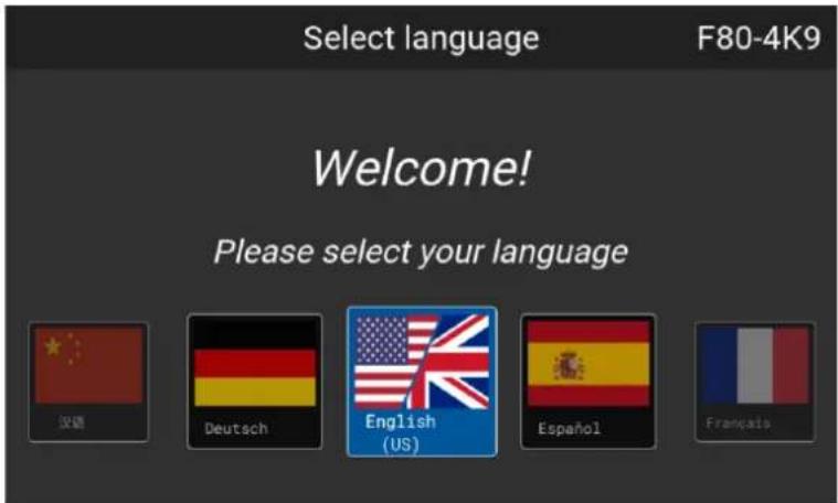
Image 1-1 Example of the welcome screen
Once confirmed, the Pulse product-specific End User License Agreement (EULA) will be prompted. Access to the projector software will be restricted until the EULA has been fully read and approved.

The EULA will not be prompted on simulation projectors (FL40, FS40, F70, F400). The EULA approval process for simulation projectors happens during the purchasing process instead.
Product Registration

The product registration is mandatory on new models of UDM, Njord and Hodr Product registration is optional on new models of QDX, 1600 and UDX.
Upon first startup the product registration menu will be prompted. Perform the registration procedure now, c choose to Register Later. For more information on the full registration procedure, refer to the Projector Registration user guide.
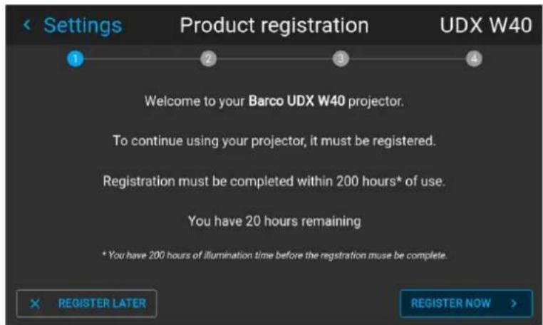
Image 1-2 Example of the Product registration form
1.3 Using the UI elements
Interacting with UI elements
Menu settings are displayed using checkboxes, sliders, and horizontal selection lists.
Use these as follows:
- Press the OK button to select or deselect a checkbox. This enables or disables a function.
- Use the arrow keys to move a slider up or down on the value line. For a slider scaled 0-9, each step equal 10% of the total value.
- Use the arrow keys to move in a horizontal selection list. Confirm the choice with the OK button.
Changes are implemented in real-time.
Scrolling through menus
When a blue vertical slider on the right side of the window is visible, this means that there are more ite show than those currently displayed.
If the vertical bar is visible, use the navigation buttons to scroll to the lower listed menu options.
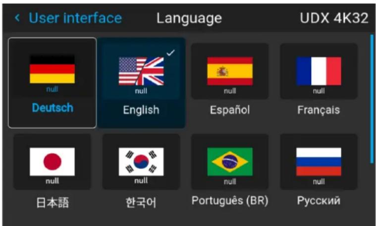
Image 1-3 Example of a menu with a vertical slider
Toggling sliders
Several icons and menu features can be enabled or disabled using toggle sliders. Using the OK button on the slider to enable or disable the feature respectively.
- When sliders are toggled to the right, they are colored blue and enabled.
- When sliders are toggled to the left, they are colored grey and disabled.
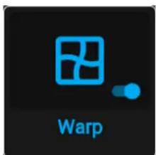
Image 1-4 Example of an enabled slider Image 1-5 Example of a disabled slider
Using the on-screen keyboard
Certain menu features require a text or a set of numbers (e.g. an IP address, a host name, etc). For the menu items, an on-screen keyboard will be prompted upon entering the input field.
Use one of the following methods for entering text:
- For characters, use the arrow keys on the RCU or local keypad to navigate the digital keyboard. Press OK button on the RCU or keypad to confirm each character.
General
- Use the LCD touch panel on the projector. Touch each desired character on the on-screen keyboard to confirm.
- While controlling the Pulse RCU, use it as follows:
- Press the numeric buttons to enter numeric values.
- Use the asterisk button (*) as backspace to remove an entered digit.
- Use the number sign button (#) button to enter a dot (.).
Once entered, press the enter (←) symbol on the on-screen keyboard to confirm the entry. As a result, the digital keyboard will be hidden.
If present in the menu, press the Apply button to confirm the entered text.
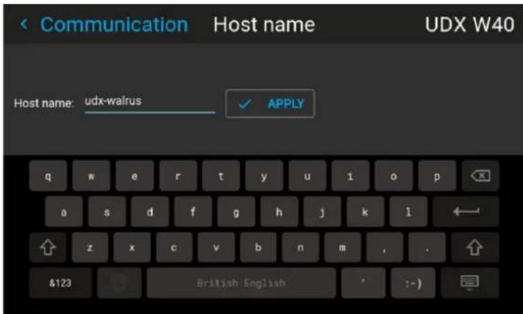
Image 1-6 Example of the on-screen keyboard
1.4 Dashboard screens
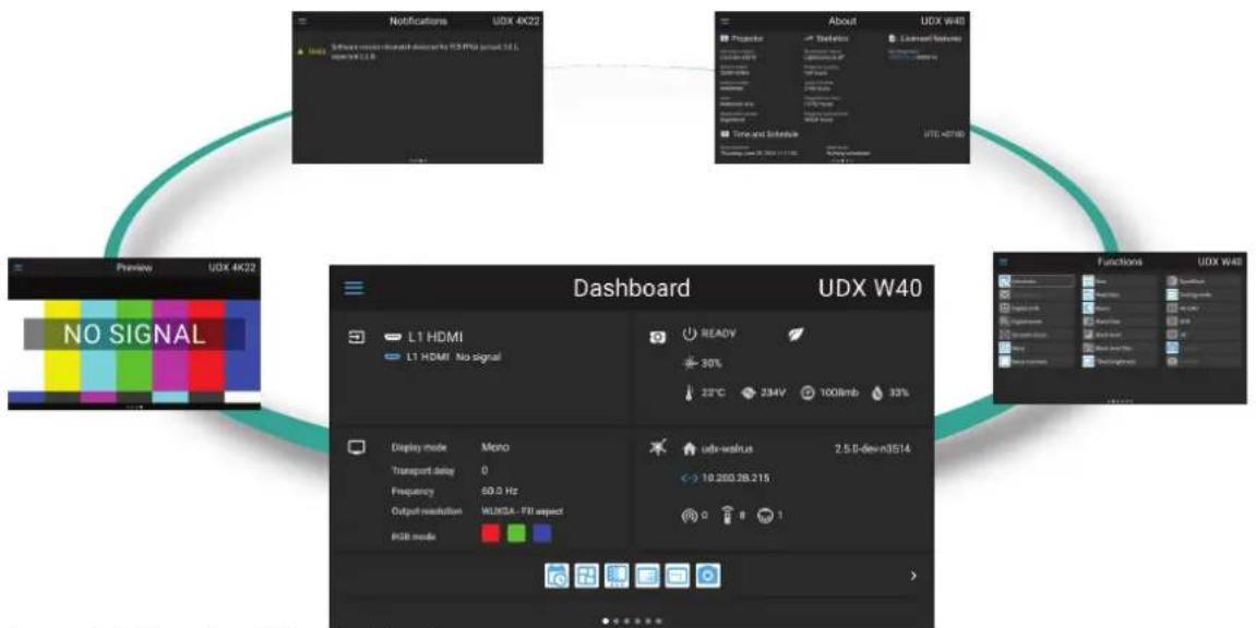
Dashboard Screens
While the projector menu is not active, or the projector is in Ready or Standby mode, the dashboard screen remain visible. These screens give an overview of the state of the projector and can be navigated through using the left and right arrow keys, or by swiping the screen left or right. The dashboard screens are the following:
Panel
Explanation
Dashboard Overview of basic projector information. Listed are the following:
- Source information: Chosen connector, connected, resolution and special coding icon (e.g. HDR)
- Projector information: Power status, light source status and general environmental condition
- Display information: Current display mode, transport delay, frequency, RGB mode and output resolution
- Communication information: Current host name, IP address, Software version, broadcast address, projector address, DMX address
Functions A list of icons of all available functions on the current model.
Pressing a shortcut will redirect you to the menu option.
See further for a detailed explanation of the Function icons.
Requirement: Pulse 2.5 or later.
About General info about the projector. This includes serial number, software version,
mounted lens and light source runtime. It also includes altitude, and the pitch and roll angles.
- Projector information: firmware, serial number, article number, lens type, registration status
- General projector statistics
• List of installed licenses
• Time and Schedule: Current time, and first upcoming scheduled event.
Note: Updated menu in Pulse 2.5
Notifications The error and/or warning messages that are currently active.
If no messages are active, this list will be empty.
Preview A preview pane of the projected image.
If no image is being projected, a “No signal” test image is displayed instead.
Note: Currently not supported on QDX, F400 and I600

Use the host name or IP address to connect to the projector using external tools, like Pulse Prospector
flowchart
graph TD
    A["Notifications UDX 4K22"] --> B["About UDX W40"]
    B --> C["Functions UDX W48"]
    C --> D["Dashboard UDX W40"]
    D --> E["Display mode Mono"]
    D --> F["Transport delay 0"]
    D --> G["Frequency 60.0 Hz"]
    D --> H["Output resolution W100A - FII aspect"]
    D --> I["RGB mode"]
    style A fill:#f9f,stroke:#333
    style B fill:#ccf,stroke:#333
    style C fill:#cfc,stroke:#333
    style D fill:#fcc,stroke:#333
Image 1-7 Example of the Dashboard screens
Functions dashboard page explanation
| Example function icon Description | Shortcut(yes/no) | |
| [5X3T] | Scheduler | White and blue icons are enabled features that are currently Yes active. |
| [HEAX] | Scheduler | |
| [3W3T] | 3D | Grey icons with white text (dark mode) or black text (light mode) are enabled, but currently not active. |
 | Digital shift | |
| [HCY6] | Test pattern | Grey icons with muted text are menu items disabled in the N current power state.Changing power state to ON will enable these features (e.g. Test patterns menu) |
| [HEAW] | Test pattern | |
| [5Z05] | Camera | Grey icons with muted text at the end of the icons list are Not accessible with the current user rights.Signing in with the correct user rights will enable the features (e.g. the Security menu requires a minimum of Power user rights). |
 | Camera | |
1.5 Navigation
Navigation using the local keypad
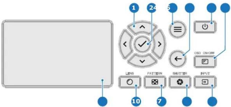
Image 1–8
1 Menu navigation keys
2 OK button, for menu confirmation
3 Menu button, opens or closes the menu
4 Back button, go up one level in the menu tree
5 Power on / off button
6 Projector OSD on / off button
7 Input button, opens the input quick selection menu
8 Shutter button, opens or closes the shutter
9 Pattern button, opens test patterns quick selection menu
10 Lens button, opens the lens feature menu.
11 LCD panel
Navigation using the basic remote
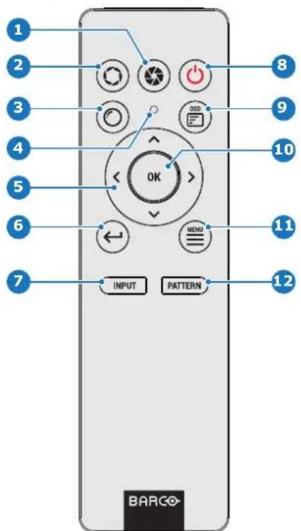
Image 1-9
1 Close shutter
2 Open shutter
3 Open Lens features menu
4 Button pressed indicator
5 Menu navigation keys
6 Back button, move back one level in menu tree
7 Input button, open Source quick-selection menu
8 Power on / off button
9 OSD menu on / off
10 OK button, for menu confirmation
11 Menu button, opens or closes the menu
12 Pattern button, openTest pattern quick-selection menu
Navigation using the Pulse RCU
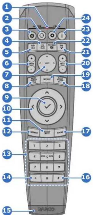
natural_image
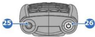
Front view of a car with two blue circular buttons labeled 25 and 26 pointing to the dashboard (no text or symbols on the car itself)Image 1–10
1 Button pressed indicator
2 Shutter open
3 Shutter close
4 LCD/Touch panel on / off
5 Projector OSD on / off
6 Lens zoom
7 Lens shift
8 Menu open / close
9 Menu selection, OK button
10 Menu navigation
11 Input selection
12 Address button
13 Numeric buttons
14 Backspace (while entering values)
15 XLR connector
16 Decimal mark (while entering values)
17 Macro button (Not in use)
18 Menu back
19 Default value button
20 Lens focus
21 RGB filter
22 Test patterns
23 Power on
24 Power off
25 3.5 mm jack
26 RCU on / off
Navigating using the LCD touch display
The LCD panel of the projectors have touch functionality. Instead of using the remote control buttons or keypad keys or button, do one of the following:
- Touch menu icons to enter the respective menu.
- Swipe a menu up and down if not all information is not immediately visible (e.g. more than eight menu icons being visible).
- Return to a higher menu level, by touching the blue name in the top left corner of the display.
- Use touch functionality to use menu items (check boxes, sliders, digital keyboard or keypads, etc).
- Swipe menu panes left or right when multiple panes are available (e.g. the Dashboard menu).
Last chosen menu
The OSD software remembers the last chosen menu as long as the projector is in Ready or On mode. The menu is turned off and on again, the software will automatically be returned to the last chosen menu.
The menu position is reset when the projector goes to Standby mode, or the projector is powered off.

For I600 and QDX, the menu position is only reset when the projector is powered off.
Projector configuration process overview
2
2.1 Prerequisites....20
2.2 Process overview 21
About this chapter
After the projector is physically installed, the configuration process can be started. This chapter gives an overview of all the different stages in the configuration process which have to be followed to get the project up and running. Each stage is briefly described and refers to more detailed step by step procedures in the manual.

Use this process overview as a checklist to ensure all stages have been followed in the configuration process of the projector.
2.1 Prerequisites
Overview
Prerequisites may vary depending on the projector model to install. The list of prerequisites provided here indicative. For more information on each prerequisite, please consult the installation manual of the projector.
List of prerequisites
The following prerequisites must be met before the projector can be configured:
- The projector must be physically installed.
- An appropriate lens must be installed in the projector lens holder.
• Install optional peripherals, systems and devices. - The necessary physical connections with source signal devices have been made.
- Define the necessary network configuration for the projector with the local network administrator.
- Turn on the projector.
- Insert batteries into the remote control (basic remote or Pulse RCU).
2.2 Process overview
Projector configuration process
- Check if all prerequisites are fulfilled. For more info see "Prerequisites", page 20
- Select the projector language and accept the EULA. For more info, see "First start of the software", page 11.
- Optionally, register the projector. For more info on the registration, see "Product registration", page 140.
- Configure the projector orientation. For more info, see "Orientation", page 74.
- Configure the network of the projector, using one of the network possibilities (LAN, WiFi or HDBaseT). For more info, see "Network setup", page 150.
-
Update the software to the latest available version. For more info, see the projector user guide.
-
Configure the broadcast address, projector address and the active IR sensors. For more info, see "Remote control", page 147.
-
Configure the projector host name, or leave the default. For more info, see "Host name - Custom projector name setup", page 149.
-
Calibrate the installed lens. For more info, see "Lens calibration", page 194.
-
Position the projector to center the projected image onto the screen or projected surface. Do this as follows:
-
Perform a lens shift action until the projected image is in the center of the projected screen. For more info, see “Configuring lens shift”, page 82.
- Adjust the projector to project perpendicular to the screen. Use one of the following methods:
- In case of table-mount installation, adjust the projector feet and consult the tilt sensor menu. For more info, see "Tilt sensor", page 77
- In case of non-motorized rigging frame, manually adjust the frame and consult the tilt sensor menu. For more info, see "Tilt sensor", page 77
- In case of motorized rigging frame, use the motorized rigging frame menu. For more info, see "Manipulating the motorized rigging frame", page 79.
-
If installed, use the optional distance meter to aid with positioning the projector. For more info, see "Laser ranging", page 75.
-
In case of projecting on a projection screen, adjust the image resolution to the screen dimensions as follows:
- Determine the Screen size that is being projected on. For more info, see "Warping – Screen size", page 93.
- Determine the desired scaling mode of the projector. For more info, see "Scaling modes", page 91.
- In case of a non-Cinemascope residential projector, use 16:9 Centered function instead. For more info, see “Cropping the image to 16:9 centered”, page 69.
- In case of a Cinemascope residential projector, crop the image according to the desired projection format and screen. For more info on cropping for Cinemascope, see “Cinemascope – Cropping the image”, page 56.
- In case of a multi-projector setup, align the projector with others in the setup as follows:
- Depending on the projected surface and area this projector will project, adjust as follows:
- Adjust the position of the four corners of the projected area. See "Warping – 4 corners adjustment", page 96
- For more free warping of the projected area, use symmetrical or asymmetrical bow correction. See "Warping – Bow", page 98
- Use blending and masking to configure the overlap between each projector in the setup. See "Blending & masking", page 107.
- Use the transport delay menu to align the latency between all projectors in the setup. See "Warping – Latency control in a multi projector setup", page 104.
- Use tilted brightness uniformity correction to adjust for "brighter" and "darker" spots in the projected area. See "Tilted brightness uniformity correction", page 50.
-
Ensure the basic projected image will be focused and sharp. Do this as follows:
-
When a motorized lens is installed, adjust the zoom and focus. For more info, see "Optical zoom and focus", page 82.
- In case of QDX, UDX and UDM with a 90^ UST lens, enable dynamic focus. For more info, see "Configuring dynamic focus on UST lens", page 83.
- For an F-Series family projector, configure the Iris. For more info, see "Configuring the Iris", page 88.
-
Fine-tune the projected image, using digital shift and zoom. For more info, see “Digital zoom and shift”, page 53.
-
Select the projection source as follows:
-
For a standard single source setup, see "Displaying a single source", page 30.
- For a multi-source setup, see "Displaying multiple sources: Stitched layouts", page 32.
-
For the details of 3D setups (including simulation and NightVision), see "3D projection", page 124.
-
If available for your model, configure your installed peripherals as follows:
-
If the external cooler is installed, set the desired cooling mode. See “Setting up the external cooler”, page 185
- If the distance meter and camera kit is installed, do the following:
- Enable the camera. See “Security – Enable camera preview”, page 204
- Measure the distance to the screen and store it for reference. See “Laser ranging”, page 75.
- If a peripheral is connected with the front XLR connector, power the front XLR connector accordingly. See “Controlling the front XLR connector”, page 182
- If the projector is part of an entire setup using DMX, configure the DMX settings. See "DMX", page 159.
- If the projector is part of an entire setup using PJLink, configure the PJLink settings. See "PJLink", page 161.
-
If peripherals are connected with the projector, using the trigger outputs, configure the triggers. See "Trigger outputs control", page 165.
-
Use the features available in the Image menu to fine-tune the projected image until the desired image is on the screen. For more info on these features, see "Image", page 41.
-
Save your current configuration in a projector profile. For more info on projector profiles, see "Projector profiles", page 129.
User rights and logging in
3
3.1 User accounts and security 24
3.2 User authentication....26
3.1 User accounts and security
About authentication
To enhance the security of the Pulse-based projectors, only basic features and parameters can be accessed without additional authentication. If access to more advanced features or parameters is needed, logging in with user name and password is required at each startup.
User authentication is enabled by default, while Pin authentication is disabled. Both can be enabled or disabled using Pulse Prospector. For more info, refer to the Pulse Prospector user guide.

Users cannot be managed using the Pulse OSD software. Users can only be managed using the Pulse Prospector. For more info on user management, refer to the Pulse Prospector user guide.
User group credentials
There are four user groups in total. Three user groups are visible and have a default user name and password.
| User group | Default user name | Default password | Default PIN |
| End User user default1234 69905 | |||
| Power User poweruser default1234 292920 | |||
| Administrator admin | default1234 297081 |
There is one hidden user group available with fixed credentials, intended for service activities that can only performed by authorized staff:
| User group | User name | Password | PIN |
| Service Partner | service | On request (see following chapter) | Not available |

CAUTION: For security reasons, it is strongly recommended to change the default password and pin codes as soon as possible. Refer to the Pulse Prospector user guide for more info.
Password and pin authentication for user group "service partner"
The password and pin code for the service partner user group are confidential for security reasons. The password and pin code can only be obtained if the user is a Barco certified service partner.
For the service pin code, the method of obtaining the code depends on the projector model family:
- For new projector families (QDX, I600, F400), send a request for the Service Partner password to Barco help desk, including the serial number of the projector(s). Help desk will generate and share the password. Each password is uniquely linked to the serial number of a projector and does not change over time.
- For older projector families (UDM, UDX, F40, F70) a generic service pin code exists, which can be obtained during the Barco-provided service partner training.

The generic service pin code will be phased out for security reasons. Similarly, on new projector models, PIN authentication will be disabled by default for security reasons. However, using Pulse Prospector, Pin authentication can still be enabled. For more info, refer to the Pulse Prospector us guide.
Role of the user groups
| Groups | Features^3 |
| End user | • Can use the basic Pulse features |
| Power user | • Can use all menu features the end user has access to• Can use the Security menu features• Can use the Diagnostic menu• Can use the following advanced settings features:- Color Wheel- Native RealColor- Statistics- Tilt sensor calibration- Laser banks- Optical filter |
| Administrator Can use all menu features the power user has access to.Can use all features of the PJLink menu. | |
| Service | • Hidden user account, reserved for certified service partners.• Cannot be deleted, renamed or otherwise edited.• Can use all menu features the administrator has access to.• Can use the following advanced settings features:- Factory native RealColor- Pixel shift- TIM curing- Laser pulsing |
3.2 User authentication
Location and availability
- Menu: Login
- Access level: all
- Models: all
- Requirements: Pulse 2.5 or later

For user authentication on older versions of Pulse, see version 00 of this user guide.
Accessing the advanced settings
Several menu items are either hidden or partially locked for the default user. Use the Login feature to have increased access to the projector features.
Once logged in, the blue key icon will remain visible on each menu title throughout the projector. The user will remain logged in as long as the Logout action on the main menu is not used. When the projector is rebooted or powered off, the user will also be logged out.
How to login
- In the main menu, select Login and confirm.
Image 3-1 Main menu, login
The Login dialog is prompted.
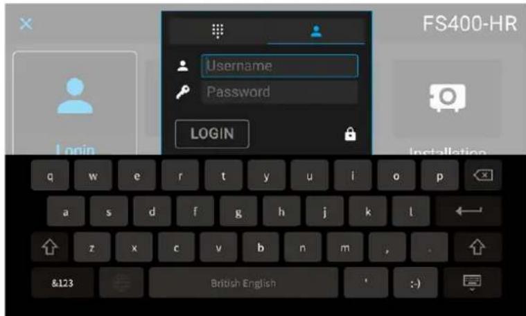
Image 3-2 Example of the login dialog
There are 2 ways to login:
• Via user name & password, go to step 2.
- Via a pin code, go to step 5.
-
To login via user name & password, select the User icon and confirm.
-
Select the field next to the user name icon and confirm.
The on-screen keyboard will be prompted. Enter the desired user name.
Select the field next to the password icon and enter the password.
- Select LOGIN and confirm.
- To login via digit code, select the digital keyboard icon and confirm.
- Navigate to Pin code and click OK.
The on-screen keyboard will be prompted. Enter the pin code. - Select LOGIN and confirm.
How to logout
- While logged in, click on the Logout icon in the main menu.
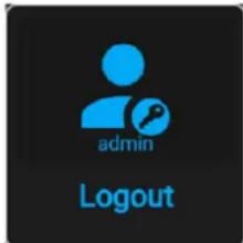
Image 3-3 Main menu, logout
- When prompted, confirm to log out.
Source
4
4.1 Displaying a single source....30
4.2 Displaying multiple sources: Stitched layouts....32
4.3 Connector settings....35
4.4 Configure override....37
4.5 No source image 39
4.1 Displaying a single source
Location and availability
- Menu: Source
- Access level: all
- Models: all

The list of available sources will be different for every projector. Check the specifications of the projector and input boards to see which input sources are available.
About selecting a source
Before a source can be projected, at least one of the input connectors must be connected to the output of the connected device(s). A valid synchronization signal must be available along with the source signal of least one of the input connectors.
When no valid source image is displayed, a black image will be projected by default, at half power. To do the background image, see "No source image", page 39.
How to select?
- In the main menu, select Source.
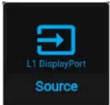
Image 4-1 Main menu, Source
The Select Source menu is displayed with the available sources listed.
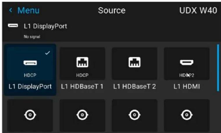
Image 4-2 Example of an input selection menu
- Select the desired input and confirm.
Shortcut buttons
When the Source icon (☐) is pressed on either the keypad or RCU, a popup menu will be prompted on the LCD screen and OSD, showing a horizontal list of the available input connectors.
Select the desired connector from the list and confirm.
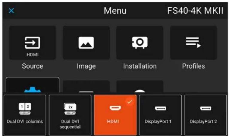
Image 4-3 Example of the input connectors pop up menu
4.2 Displaying multiple sources: Stitched layouts
Location and availability
- Menu: Source
- Access level: all
- Models: all

The list of available sources and stitched options will be different for every projector. Check the specifications of the projector and input boards to see which sources are available.
About stitched layouts
The first time a single source is selected, the source will be displayed in the projector's native resolution. If the resolution of the source is different to the projector's resolution, the image is stretched or shrunk.
It is however possible to configure and display two or four source signals to make up one single image in native resolution. This is called a Stitched Layout: the sources are stitched together.
Possible stitched layouts
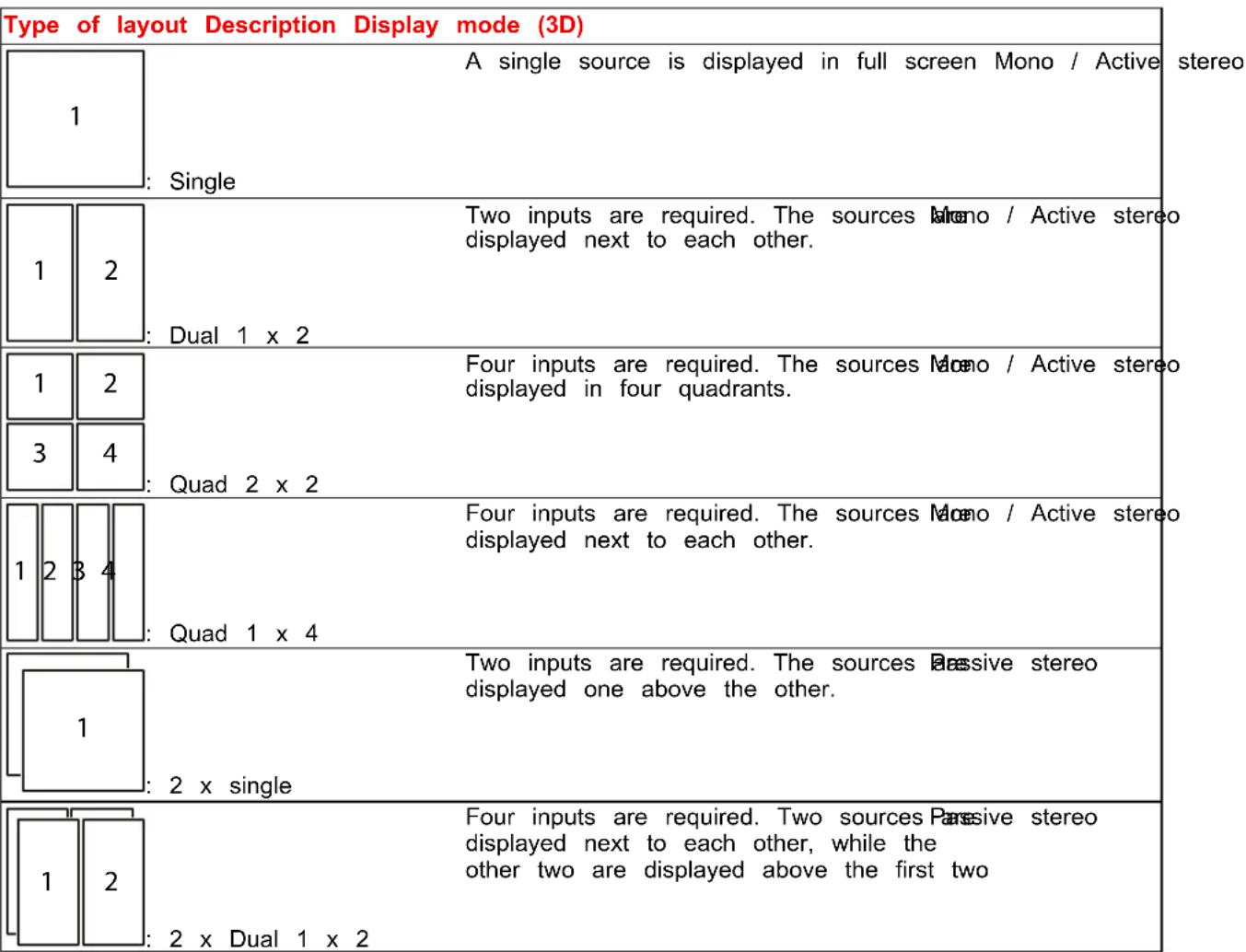 |
How to select a stitched layout
- Press Menu to activate the menus, select Source and confirm.
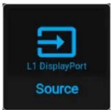
Image 4-4 Main menu, Source
The Select Source menu is displayed with the available sources listed.
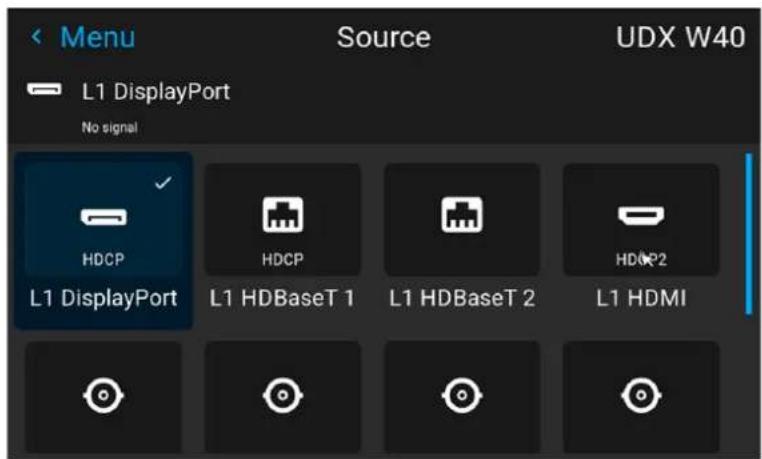
Image 4-5 Example of an input selection menu
- Scroll down the list of available sources to find the available stitched options.
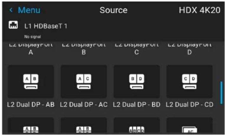
Image 4-6 Example of the stitched input options when the Quad DP board installed
- Select the desired stitched input.
Shortcut buttons
When the Source icon (☐) is pressed on either the keypad or RCU, a popup menu will be prompted on the LCD screen and OSD, showing a horizontal list of the available input connectors, including stitched options. Select the desired stitched option from the list and confirm.

Image 4-7 Example of the input connectors pop up menu
4.3 Connector settings
Location and availability
- Menu: Source > Connector settings
- Access level: all
- Models: all

The list of available sources will be different for every projector. Check the specifications of the projector and input boards to see which input sources are available.
About connector settings
The Connector Settings menu allows the user to change settings for each input connector of the projector.
By default all options for every connector are set to automatic, together with the native Extended Display Identification Data (EDID).
When entering the menu for each input connector, the following can be changed:
- Color Space
- Signal Range
• EDID
How to configure a connector
- Scroll down to the bottom of the list of available sources in the Source menu and select Connector settings.
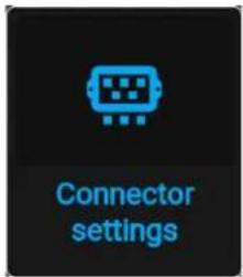
Image 4-8 Source menu, connector settings
The available input connectors are displayed.
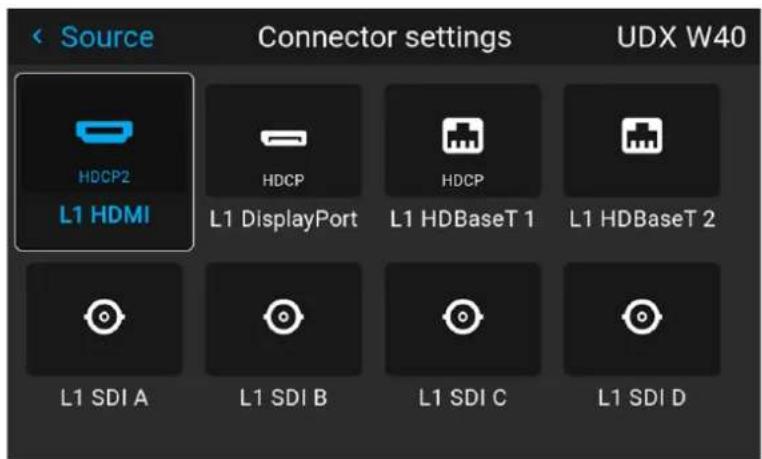
Image 4-9 Example of the Connector settings menu
- Select the desired connector.
The connector settings menu for the selected connector will be displayed.
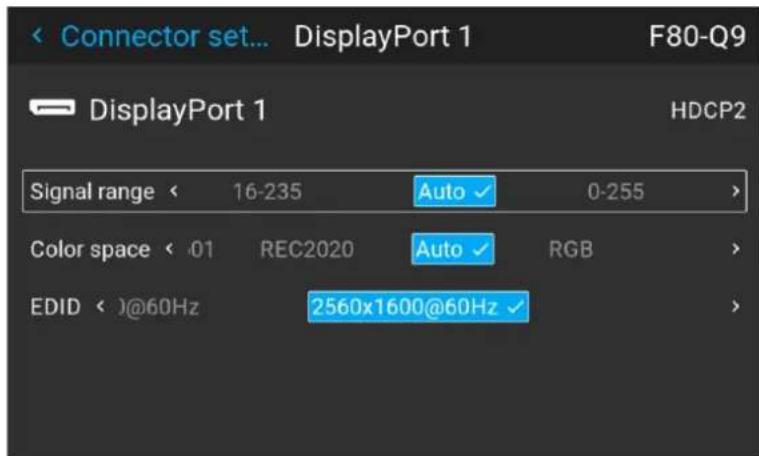
Image 4-10 Example of connector settings for one of the connectors
- Do one of the following:
• To force a limit on the used signal range, select one of the available signal ranges.
• To force a limit on the color space, select one of the available color spaces.
• To set a video timing other than the one native for the connector, select one of the options under EDID.

Note: The EDID for SDI connectors cannot be changed.
4.4 Configure override
Location and availability
- Menu: Source > Connector Settings
- Access level: all
• Models: F40, F70, F400
About overriding the connector configuration
If there is a stitched layout in the projector setup, it may be necessary to override the settings of each connector individually. Using this, the following image settings can be altered:
- Brightness
- Contrast
- Saturation
- Gamma type
How to override the configured connector
- In the Connector settings menu, select the desired connector and confirm. The Connector Settings menu for this connector will be displayed.
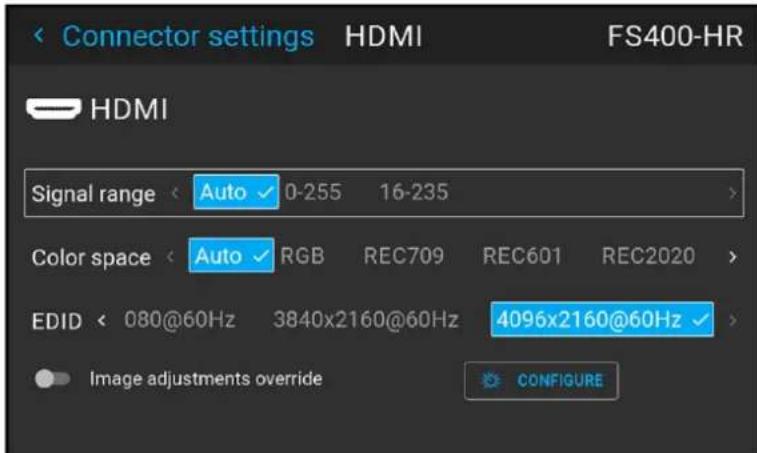
Image 4-11 Example of connector settings for an HDMI connector
-
Enable the Image adjustments override slider.
-
Click Configure.
The Configure overrides menu is displayed.
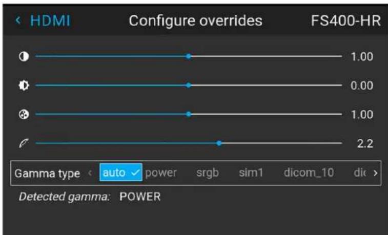
bar
| Gamma type | Configure overrides | | ---------- | ------------------- | | 1 | 1.00 | | 2 | 0.00 | | 3 | 1.00 | | 4 | 2.2 |Image 4-12 Example of the Configure overrides menu
- Set the desired override values for contrast, brightness, saturation and gamma type.

Tip: For more info on how to change these image settings, see "Image", page 41.
4.5 No source image
Location and availability
- Menu: Source > No source image
- Access level: all
- Models: all
What happens when no valid signal is selected
If no source with valid signal is selected, a default background image will be projected instead. However, projected image when no source is selected can be customized.
Select one of the predefined backgrounds (full Black or full Blue), or upload a custom image using an ex-tool like Pulse Prospector (e.g. project a company logo instead).

While no source with an active signal is selected and the OSD is not projected on screen, the light source power will be reduced to 50% after 10 seconds as a light source power saving feature. The power saving feature can be disabled in the Auto dim menu. For more info, see "Auto dimming", page 180.
How to change
- Scroll down the list of available sources in the Source menu and select No source image.

Image 4–13 Source menu, No Source image
The No source image menu is displayed.
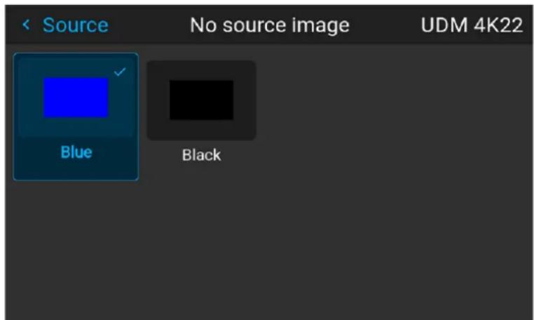
Image 4–14 Example of the No source image menu
- Select the desired image to project when no source image is available.

Custom background images will be listed after the predefined images.
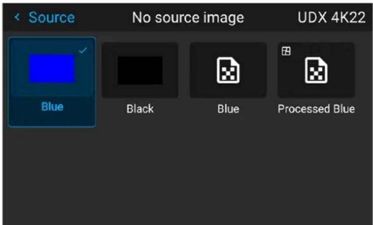
Image 4–15 Example of the No source image menu with two custom background images.
Image
5
5.1 Adjusting contrast....42
5.2 Adjusting brightness 43
5.3 Adjusting the saturation....44
5.4 Adjusting the sharpness....45
5.5 Adjusting the gamma correction....47
5.6 Setting the desired gamma type....48
5.7 Tilted brightness uniformity correction 50
5.8 Digital zoom and shift....53
5.9 Cinemascope – Cropping the image....56
5.10 Advanced image setting....61
5.1 Adjusting contrast
Location and availability
- Menu: Image > Contrast
- Access level: all
- Models: all
About contrast
The contrast function is used to adjust the difference between the darker and lighter colors. It does this b applying or removing gain to the red, green and blue signals.
Adjusting contrast can improve the image quality when the projector is set up in darker environments.
How to set up contrast
- In the Image menu, select Contrast.
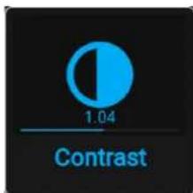
Image 5-1 Image menu — Contrast
The Image settings menu is displayed.
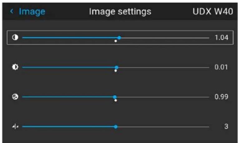
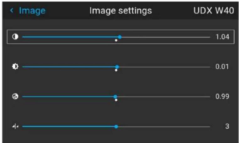
line
| Image Settings | Value | | -------------- | ----- | | 1 | 1.04 | | 2 | 0.01 | | 3 | 0.99 | | 4 | 3 |Image 5-2 Example of the image sliders, contrast is the first slider
- Use the ◀ or ▶ key to change the contrast enhancement until the desired value is reached.
• Available range: 0.00 to 2.00
- Default value: 1.00
- If necessary, use the ▲ or ▼ key to select the other image adjustment options.
5.2 Adjusting brightness
Location and availability
- Menu: Image > Brightness
- Access level: all
- Models: all
About brightness
The brightness setting on a projector controls the intensity of the projected image.
Increasing brightness can be useful when the projector is set up in “bright” environments (e.g. direct sunlight lots of spotlights, etc), where the projected image would otherwise be difficult to see. However, increasing brightness comes at the cost of more washed-out colors and reduced contrast.
Reducing brightness can be useful in dark environments (e.g. caves, rooms without sunlight, etc), in order enrich the projected colors. However, take into account
How to set up brightness level
- In the Image menu, select Brightness.
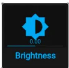
Image 5-3 Image menu - Brightness
The Image settings menu is displayed, the brightness slider will be highlighted.
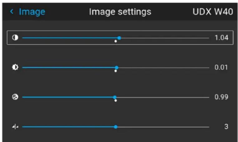
line
| Image Settings | Value | | -------------- | ----- | | 1 | 1.04 | | 2 | 0.01 | | 3 | 0.99 | | 4 | 3 |Image 5-4 Example of the image sliders, brightness is the second slider
- Use the ◀ or ▶ key to change the brightness slider until the desired brightness is achieved.
• Available range: -1.00 to +1.00
- Default value: 0.00
- If necessary, use the ▲ or ▼ key to select the other image adjustment options.
5.3 Adjusting the saturation
Location and availability
- Menu: Image > Saturation
- Access level: all
- Models: all
About saturation
Saturation impact on the white levels and the intensity of the projected colors. A picture with low saturation have muted or subdued colors, whereas an image with high saturation will have more vibrant colors.
If only one type of content will be projected, the saturation can be adjusted to optimize the projected cold this specific content.
However, take into account that different types of content may require a different level of saturation.
How to set up saturation level
- In the Image menu, select Saturation.
Image 5-5 Image menu - Saturation
The Image settings menu is displayed. The saturation slider will be highlighted.
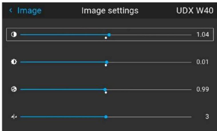
bar
| Image setting | Value | | ------------- | ----- | | 1 | 1.04 | | 2 | 0.01 | | 3 | 0.99 | | 4 | 3 |Image 5–6 Example of the image sliders, Saturation is the third slider
- Use the ◀ or ▶ key to change the saturation until the desired value is reached.
• Available range: 0.00 to 2.00
- Default value: 1.00
- If necessary, use the ▲ or ▼ key to select the other image adjustment options.
5.4 Adjusting the sharpness
Location and availability
- Menu: Image > Sharpness
- Access level: all
- Models: all
About sharpness
The sharpness adjustment amplifies the high frequency components in the picture. Increasing the sharpness of the source may help pictures and text stand out as sharper. In case of text (e.g. spreadsheets, presentations), text may become more readable. However, take into account the following when projecting images or movies:
- An image with low sharpness may be perceived as "blurry".
- An image with high sharpness may have "image noise" present.
Adjust the sharpness to avoid both image noise and blur as much as possible.
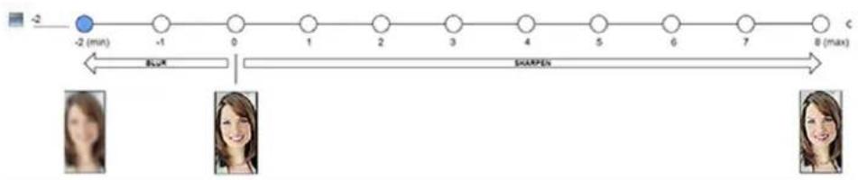
flowchart
graph LR
    A["-2 (min)"] --> B["-1"]
    B --> C["0"]
    C --> D["1"]
    D --> E["2"]
    E --> F["3"]
    F --> G["4"]
    G --> H["5"]
    H --> I["6"]
    I --> J["7"]
    J --> K["8 (max)"]
    style A fill:#000,stroke:#fff,color:#fff
    style K fill:#000,stroke:#fff,color:#fff
    subgraph Time_Steps
        L["Blue"] --> M["Blue"]
        N["Sharpen"] --> O["Sharpen"]
    end
Image 5-7 Example of the effect of sharpness on images
How to adjust the sharpness
- In the Image menu, select Sharpness.
Image 5–8 Image menu – Sharpness
The Image settings menu is displayed. The sharpness slider will be highlighted.
line
| Image Settings | Value | | -------------- | ----- | | 1 | 1.04 | | 2 | 0.01 | | 3 | 0.99 | | 4 | 3 |Image 5-9 Example of the image sliders, Sharpness is the bottommost slider
- Use the ◀ or ▶ key to change the sharpness until the desired sharpness is reached.
• Available range: -2 to 8.
Image
- Default value: 0
- If necessary, use the ▲ or ▼ key to select the other image adjustment options.
5.5 Adjusting the gamma correction
Location and availability
- Menu: Image > Gamma
- Access level: all
- Models: all
About gamma correction
Gamma correction is an image quality enhancement function that offers a richer image by brightening the already darker portions of the image without altering the brightness of the brighter portions (contrast feeling enhanced).
How to adjust
- In the Image menu, select Gamma.
Image 5–10 Image menu - Gamma
The "Gamma" menu is displayed.
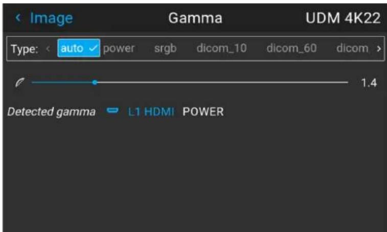
Image 5–11 Example of the gamma menu
- Select the gamma slider.
- Use the ◀ or ▶ key to change the gamma until the desired value is reached.
• Available range: 1.0 to 2.8
- Default value: 2.2
- Step precision: 0.1
5.6 Setting the desired gamma type
Location and availability
- Menu: Image > Gamma
- Access level: all
- Models: all
About gamma types
Next to the standard gamma correction, projectors can be manipulated in a way to simulate gamma types other devices or purposes. This includes sRGB (standard Red-Green-Blue), Power gamma, DICOM gamma ranges and for simulation projectors sim1.
DICOM gamma ranges are usually reserved for medical displays. While this projector is not a certified DICOM display, it can simulate certain specific DICOM gammas at a few selected max light outputs. The DICOM gamma assumes that both ambient light and the projector outputs black as 0 cd/m². Then there will be a predefined gamma curves at the following light outputs:
• DICOM 10: 10 cd/m²
• DICOM 60: 60 cd/m²
• DICOM 180: 180 cd/m²
• DICOM 250: 250 cd/m²
• DICOM 300: 300 cd/m²
• DICOM 400: 400 cd/m²

This is the full list if DICOM gammas. Some projector models will have a more restricted list.
Gamma types for residential models
Because of the more limited use cases in residential environments, the amount of gamma types for residential models is limited to the following gamma types:
• sRGB (standard Red-Green-Blue)
- Power
Exception when using an HDR source
HDR/PQ is the only alternate color gamma that can not be selected in the Gamma menu. Because the c output of HDR is dependant on extra factors such as screen luminance, a separate menu has been made available for this. For more info on this separate menu, see "Displaying HDR content", page 64.
If the source signal is HDR encoded an HDR icon will be visible next to the source signal. This is visible the Source selection menu, as well as the Dashboard menu.
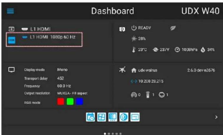
Image 5-12 Example of the HDR icon on the Dashboard menu
How to adjust the gamma type?
- In the Image menu, select Gamma.
Image 5-13 Image menu - Gamma
The Gamma menu is displayed.
If source content is available, the detected gamma of the source will be displayed at the bottom of the menu.
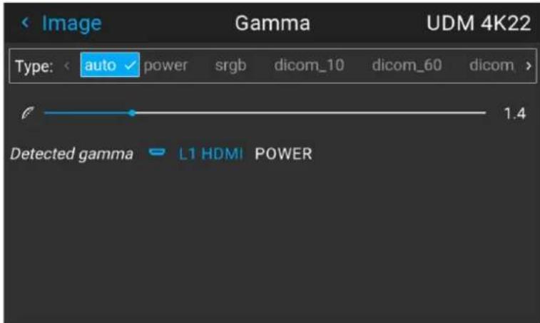
Image 5–14 Example of the gamma menu
- Use the ◀ or ▶ key to select the desired gamma type and confirm.
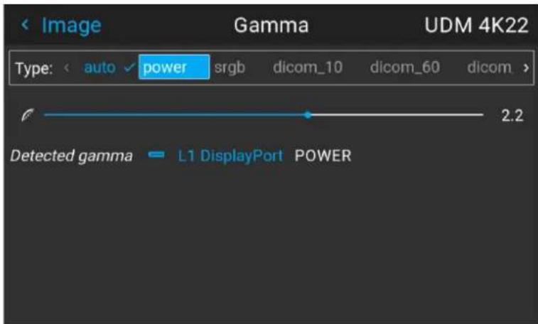
Image 5–15 Example of selecting a gamma type

Tip: If not sure what gamma type to select, keep the default value auto selected. This automatic mode will determine the used gamma type based on the incoming signal.
However: keep in mind when using the automatic mode, the media player will need to be configured correctly as well. While most mainstream media player devices will be configured correctly by default, Barco cannot guarantee this is the case for every device available on the market. If the projected image seems “off”, it may be necessary to check the configuration of the media player. For more info, check the user guide of the media player device.
5.7 Tilted brightness uniformity correction
Location and availability
- Menu: Image > Tilted brightness uniformity
- Access level: all
- Models: all

The Tilted brightness uniformity correction feature is only enabled when the light source is on
What is tilted brightness uniformity correction?
Projectors can be installed at any angle possible. However, this can result in the lens being positioned in angle (horizontal or vertical) towards the projection surface.
Due to this, one side of the projected surface can become brighter than the other (left versus right side, versus bottom side or both). While a slight difference in brightness might not be that noticeable in a single projector setup, when having the projector installed in a multi-projector setup brightness differences can possibly ruin immersion.
The Tilted brightness uniformity menu allows the user to correct the projected image, so that every side of the projected image looks equally bright.
How is the correction applied?
The Tilted brightness uniformity menu has two adjustment options, applying a “darkness gradient” over the horizontal and/or vertical axis. This is applied as follows:
- A positive horizontal correction will result in the right side of the screen becoming less bright than the I side.
- A negative horizontal correction will result in the left side of the screen becoming less bright than the right side.
- A positive vertical correction will result in the bottom side of the screen becoming less bright than the t side.
- A negative vertical correction will result in the top side of the screen becoming less bright than the bottom side.

natural_image
Simple diagram showing a gray arrow pointing right from a white rectangle to a gradient-filled rectangle (no text or symbols)Image 5–16 Example of a (maximum) negative horizontal correction being applied on the projected image.

natural_image
Simple gray arrow pointing right from a vertical line, no text or symbols presentImage 5–17 Example of a (maximum) negative vertical correction being applied to the projected image.

natural_image
Simple diagram showing a gray arrow pointing right from a white rectangle to a grayscale gradient bar (no text or symbols)Image 5–18 Example of a maximum negative correction on both horizontal and vertical axes to the projected image.
Required tools
Light meter
How to adjust brightness across the screen
- In the Image menu, select Tilted brightness uniformity.
Image 5–19 Image menu, Tilted brightness uniformity
The Tilted brightness uniformity menu is displayed.
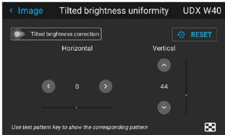
Image 5-20 Exampe of the Tilted brightness uniformity
-
Enable the Tilted brightness correction slider.
-
Use the Test Pattern button on the RCU to project the full white test pattern.

Tip: While any test pattern or projected image can be used, the best result will be achieved while projecting the full white test pattern.
-
Use a light meter to measure the brightness on the left side, center and right side of the projected surface.
-
Adjust the brightness on the Horizontal axis until the left and right side of the projected surface are equally bright.
-
Use a light meter to measure the brightness on the top side, center and bottom side of the projected surface.
-
Adjust the brightness on the Vertical axis until the top and bottom side of the projected surface are equally bright.
-
Repeat the previous steps until the brightness is even across all sides of the projected surface.

Press the Reset button in case of mistakes. When pressed, both the horizontal and vertical axis will return to the center value.
5.8 Digital zoom and shift
Location and availability
- Menu: Image > Digital zoom and shift
- Access level: all
• Models: QDX, UDM, UDX, I600, F40, F70, F400
What can be done?
The image can be optically shifted by using the vertical and horizontal lens shift.
If a lens shift beyond what is possible with the optical shift is desired, a digital lens shift can be performed digital shift will occur on the DMD, rather than the lens holder. So take into account that this additional small and restricted to the limits of the chip used.
For more info on the optical zoom and lens shift, see "Optical zoom and focus", page 82.

Lens shift is only possible when the used lens has been fully calibrated. For more info on how to calibrate the lens, see "Lens calibration", page 194.
The effect of digital zoom
This function zooms in the picture digitally. When zooming in, the center of the image will increase in size means that the outer part of the picture will be outside the picture frame. When zooming out, the result is the picture will be smaller than the projectors picture frame. The area outside the rendered picture will be black.
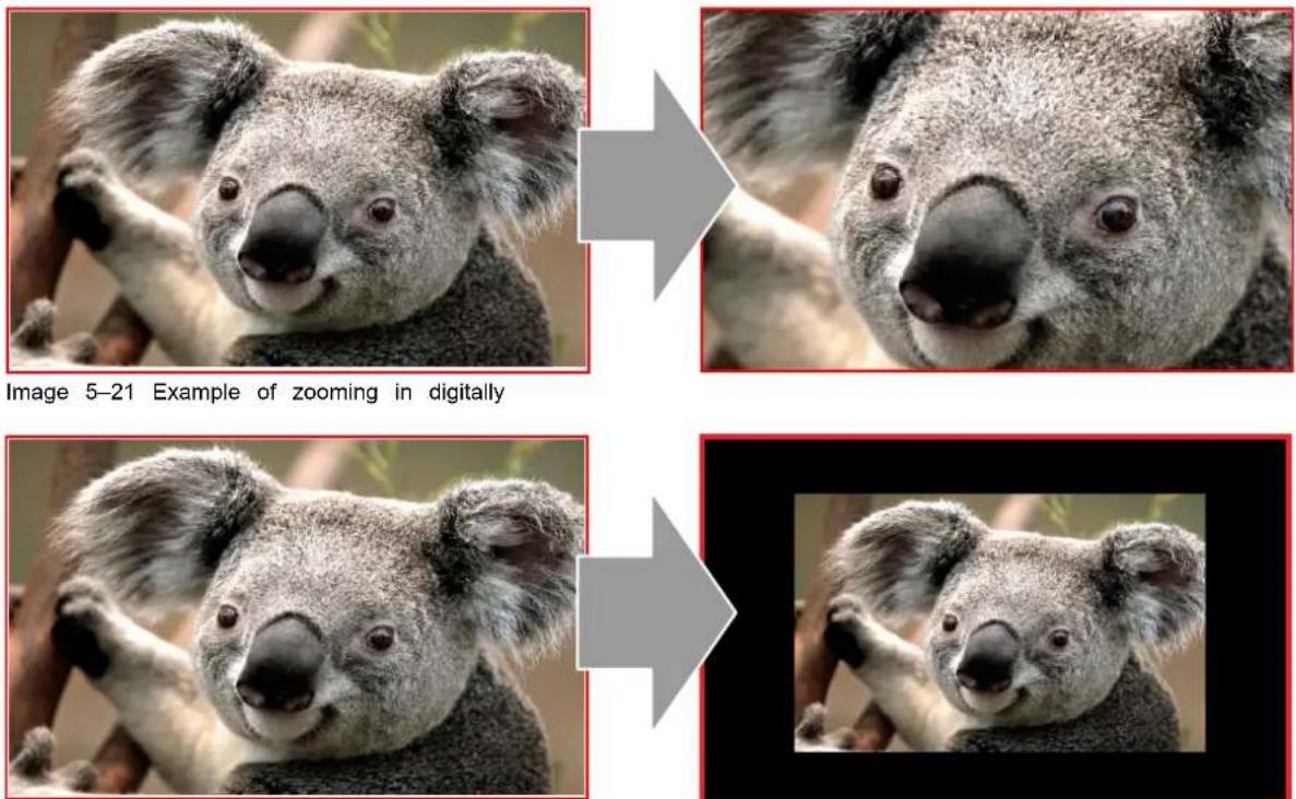
Image 5–22 Example of zooming out digitally
The effect of digital shift
This function will shift the picture digitally, meaning that the picture will be moved in any direction. As a some parts of the picture might be shifted outside the DMD range.
Image

natural_image
Two identical photos of a koala with a smiling face, connected by an arrow to the right image (no text or symbols)Image 5-23 Example of shifting digitally on the horizontal axis

natural_image
Close-up comparison of a koala's face before and after transformation, showing the original vs. corrected version (no text or symbols)Image 5-24 Example of shifting digitally on the vertical axis
Digital shift and zoom
- In the Image menu, select Digital zoom and shift.
Image 5–25 Image menu, digital zoom and shift
The Digital zoom and shift menu is displayed.
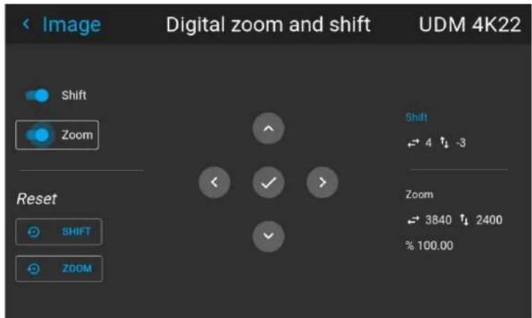
Image 5-26 Example of the digital zoom and shift menu
-
Enable the Shift and/or Zoom sliders to enable digital shift and/or digital zoom respectively.
-
When one or both of the modes are enabled, use the arrow keys to select the mini-keypad in this menu. Use the enter key to activate this mini-keypad.
If digital shift is enabled, the keypad will transform into the keypad for digital shift. If only digital zoom active, it will automatically transform in the keypad for digital zoom.
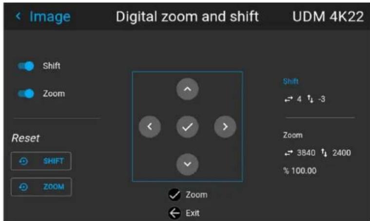
Image 5-27 Example of the enabled digital shift mode
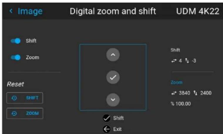
Image 5-28 Example of the enabled digital zoom mode
- If digital shift is enabled, do the following:
• Use the ◀ or ▶ key to shift the lens (image) in horizontal direction.
- Use the ▲ or ▼ key to shift the lens (image) in vertical direction.
- Use the enter key to transform the keypad to digital zoom mode (if enabled).
- Use the return key to exit without saving.
-
If digital zoom is enabled, do the following:
-
Use the ◀ or ▶ key to zoom the lens in or out.
- Use the enter key to transform the keypad to digital shift mode (if enabled).
- Use the return key to exit without saving.
5.9 Cinemascope – Cropping the image
Location and availability
- Menu: Image > Cropping
- Access level: all
• Models: Bragi Cinemascope, Balder Cinemascope, Njord Cinemascope, Hodr Cinemascope

On non-Cinemascope projectors, this feature is replaced with the 16:9 centered function. For more info, see "Cropping the image to 16:9 centered", page 69.
About this chapter
This chapter talks about how to crop content according to the used media player and/or content mastering
5.9.1 Introduction to Cinemascope and image cropping
About Cinemascope and home media releases
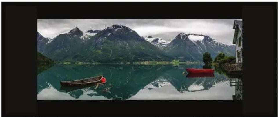
Today, most movies released in commercial theaters are mastered with the 2.39:1 aspect ratio of Cinemascope. When a Cinemascope movie is released through modern media, it uses a 1920x800 (or 3840x1620 in 4K) resolution.
However, home media content like Blu-Rays and DVDs are released with an aspect ratio of 16:9, either in 1920x1080 or 3840x2160 (in 4K). Due to the limitations of the approach used, the pixel difference between Cinemascope content and home media content is shown as the much-dreaded “black horizontal bars”.
When this image with black horizontal bars is projected on a high-end 2.35:1 aspect ratio screen, then en result will be an undesired image with black bars on all sides.
natural_image
Scenic mountain lake with snow-capped peaks reflected in calm water, two small boats on the water surface (no text or symbols visible)Image 5–29 Example of a Cinemascope movie projected on a 2.35:1 aspect ratio screen without image cropping enabled
About image cropping
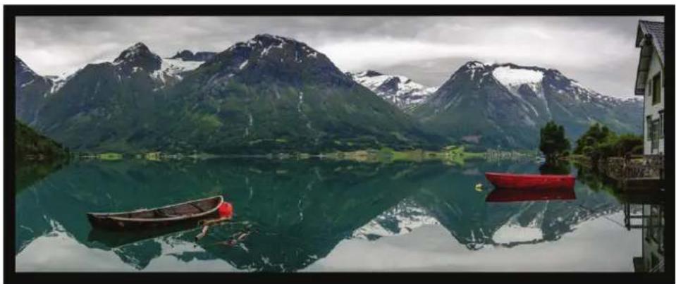
To avoid the situation with “surrounding black bars”, the image cropping feature uses advanced image processing to scale the image diagonally.
The Cropping feature is a process where the image maintains a perfect geometry while utilizing more pixel. This way it is ensured that the entire 2560x1080 (or 5120x2160 in 4K) space is fully used and real Cinemascope can be experienced.
natural_image
Scenic mountain lake with snow-capped peaks reflected in calm water, two small boats on the water (no text or symbols visible)Image 5–30 Example of the same Cinemascope movie on the same 2.35:1 screen, but with image cropping enabled
There are three cropping modes: preset, manual and auto.
- Auto cropping, or cropping using the automatic aspect ratio detection algorithm. For more info, see "Image cropping – auto cropping", page 57.
- Cropping via aspect ratio presets. For more info, see "Image cropping – using aspect ratio presets", page 58.
- Manual cropping. For more info, see "Image cropping – manual cropping", page 59.

All cropping is done dynamically. For best result Barco recommends to pause the movie currently screen, making sure that any subtitles or other text is visible. Once paused, activate the cropping function.
5.9.2 Image cropping - auto cropping
Auto aspect ratio detection
The “Auto” mode has the unique automatic aspect ratio detection function. This will check if the provided media is mastered in 2.39:1 content and will automatically scale the image to fit the 2560x1080 (or 5120x in 4K) resolution. It will also change back to 16:9 (1920x1080 or 3840x2160 in 4k) if the content in this
The function will also change the aspect ratio when a 2.39:1 format movie has content menus outside of active picture frame (as shown in the following example image). When activating this type of menu, or wh changing to 16:9 content, the projector will then automatically adjust the image shape.
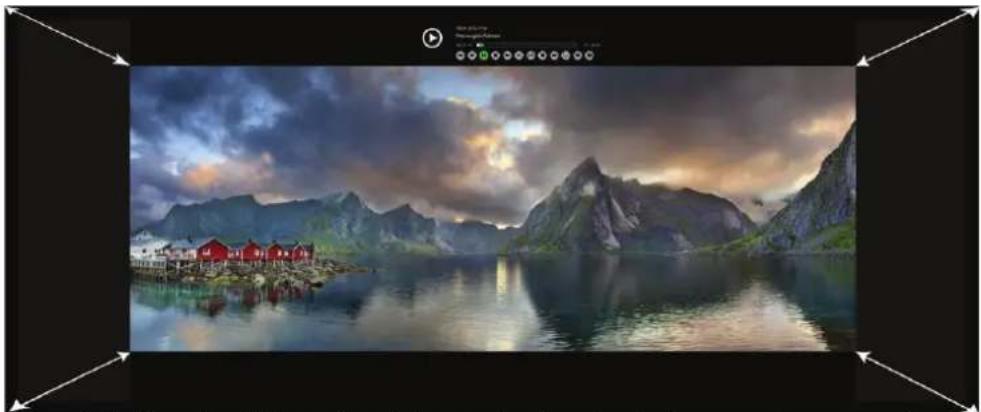
natural_image
Scenic mountain lake landscape with red-roofed buildings and cloudy sky, framed by black borders (no text or symbols)Image 5–31 Example of the projected image changing due to the content menu popping up above the movie content

The auto detection feature will only work in the aspect ratios mentioned in the presets list. Unliste aspect ratios will not be recognized. If the content aspect ratio does not match any of the listed presets, use manual cropping instead. "Image cropping – manual cropping", page 59
Watermarks and graphic content in the horizontal black bars
One thing to keep in mind with the auto-cropping feature is the potential of content being present in the horizontal black bar area. This content can take shape in the way of watermarks and logos (e.g. the BE logo), hard coded subtitles, or other visual flair added by the content publisher. If present, these graphic additions will be considered as “content” by the detection algorithm and the image will be projected with b bars on all sides instead.
If content is present in the black horizontal bars, enable the Video content slider. When enabled, only the movie area will be shown. Content outside of the movie area will be removed by the cropping algorithm. will ensure the projected image remains stable without interference from any added graphic content.
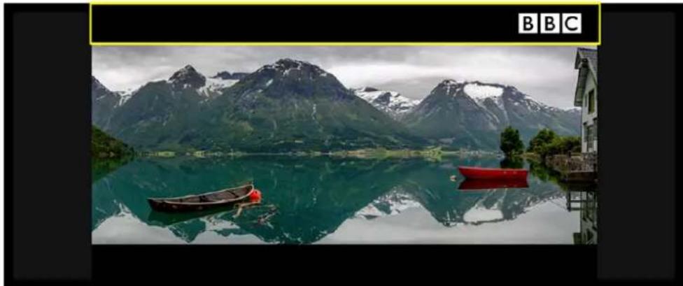
natural_image
Scenic mountain lake with snow-capped peaks reflected in calm water, two small boats on the water (no text or symbols visible)Image 5-32 Example of the projected image decreasing due to the presence of the BBC logo
How to use auto aspect cropping
- In the Image menu, select Cropping.
The Cropping menu is displayed.
- Select Auto.
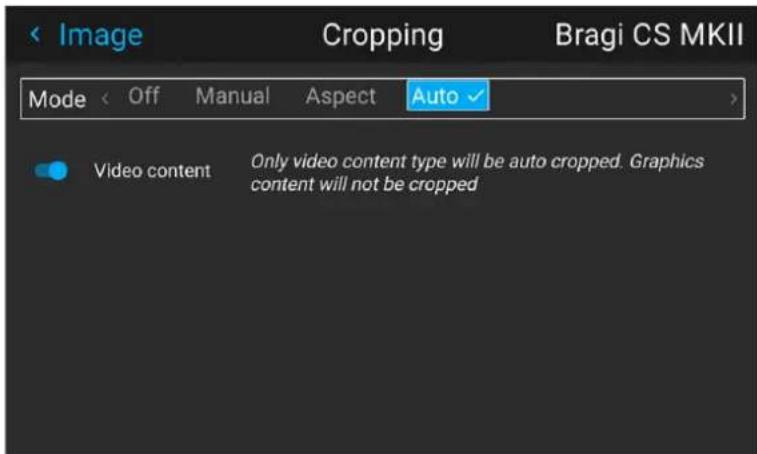
Image 5-33 Example of the Cropping menu - Auto
- If content in the black bars needs to be removed, enable the video content slider.
5.9.3 Image cropping - using aspect ratio presets
Available cropping presets
If the provided content fits with one of the more common aspect ratios, select the applicable preset to automatically fix the projected image.
The available presets are the following:
• 16.9: HDTV standard, used in most home media releases.
• 1.85:1: "Flat" widescreen cinema standard for 35 mm film
• 1.9:1: DCI standard for 4K, 2K and digital IMAX
• 2.0:1: Univisium standard
• 2.2:1: Standard for 70 mm film (e.g. Super Panavision)
• 2.35:1 Cinemascope standard for 35 mm film (mastering pre 1970)
• 2.37:1: Near-cinematic widescreen. Also known as 21:9 or 64:27
• 2.39:1: Cinemscope standard for 35 mm film (mastering post 1970).
When one of these presets is selected, the projected image will be scaled to fill the projection screen ver while respecting the selected aspect ratio at the same time. This means that, depending on the chosen as ratio and projection screen, there may be vertical black bars at the side of the picture.
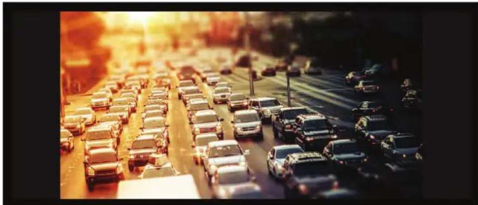
natural_image
Highway traffic scene at sunset with multiple cars driving, no visible text or signageImage 5–34 Example of 16:9 mastered content on a 2.35:1 screen, with black bars on the left and right of the image
In the case where the content format is mastered in a format not covered by the list of presets, it is ac use manual cropping instead. For more info, see "Image cropping - manual cropping", page 59.
How to use the aspect ratio presets
- In the Image menu, select Cropping.
The Cropping menu is displayed.
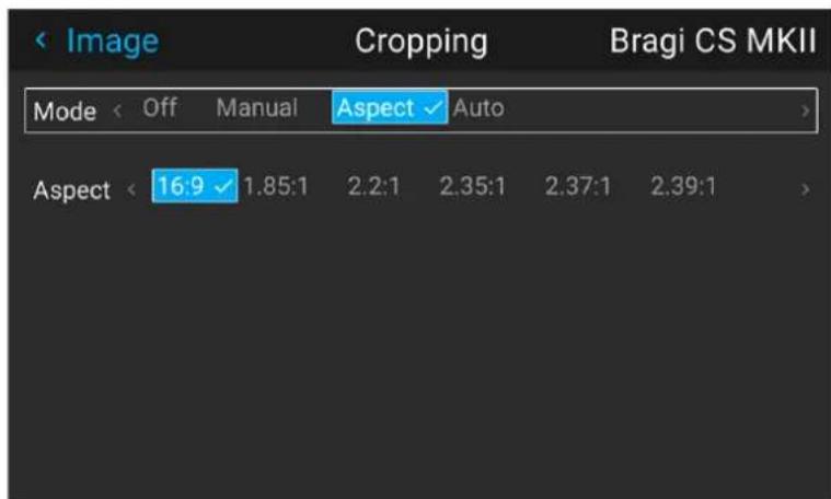
Image 5-35 Example of the cropping menu
- Select Aspect to display the Aspect ratio presets.
- Select the desired Aspect ratio and confirm.
5.9.4 Image cropping - manual cropping
About manual cropping
When the provided media content does not match any of the provided aspect ratio presets, it is advised a manual mode instead.
In order to do know how many lines need to be cropped, calculate how large the area is that has black. For example, the Cinemascope 2.37:1 format distributed on a regular Blu-ray disc will have 200 lines on the Top and Bottom area that will need to be cropped out.
How to perform manual cropping
- In the Image menu, select Cropping.
The Cropping menu is displayed.
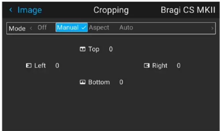
Image 5–36 Example of the cropping menu
- Select one of the four sides where black bars are visible.

Tip: As black horizontal bars are the most common occurrence in the world of media (when compared to vertical bars), it is advised to start cropping with the Top area and then the Bottor area. Only if no perfect fit frame can be reached, crop the side areas.
- Enter the number of lines that will need to be cropped out and confirm.
- Repeat for each side where black bars are visible, until a complete picture is formed on screen.

If the provided content has subtitles hard coded into the black bars region, manually crop the picto to cut out as much as possible while retaining the area with subtitles.
For example, crop out the entire top black bar, and crop out just enough lines from the bottom bar to make sure the subtitles are still readable.
5.10 Advanced image setting
5.10.1 RealColor P7 - Custom P7 settings
Location and availability
- Menu: Image > Advanced settings > RealColor P7
- Access level: all
- Models: all
Purpose
When blending images from multiple projectors, the measured color coordination of each projector can be altered to a desired common level. This so that the projected colors are identical over all projectors used. Alternatively, there are a number of presets available, which forces the color output to specific color standard
How to set custom P7 values
- In the Advanced settings menu, select RealColor P7.
Image 5-37 Advanced settings menu - RealColor P7
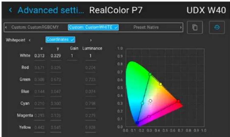
The RealColor P7 menu is displayed.
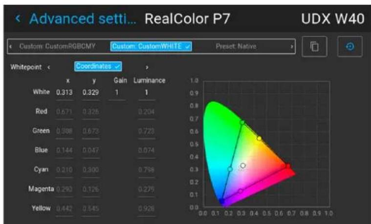
other
| Whitepoint | x | y | Gain | Luminance | | ---------- | ---- | ---- | ---- | --------- | | White | 0.313| 0.329| 1 | 1 | | Red | 0.671| 0.325| 0.204| | | Green | 0.388| 0.673| 0.723| | | Blue | 0.144| 0.047| 0.074| | | Cyan | 0.210| 0.300| 0.798| | | Magenta | 0.293| 0.126| 0.279| | | Yellow | 0.442| 0.545| 0.928| |Image 5-38 Example of the RealColor P7 menu, here on a UDX
-
Select the desired Custom Mode. Select one of the following Custom options and confirm:
-
Custom RGB: 3-point color configuration.
In RGB mode, the C, M and Y coordinates will be calculated automatically based on the R, G and coordinates. - Custom RGBCMY: 6-point color configuration (both RGB and CMY).
In RGBCMY mode, each color can be given a specific coordinate within the measured color triangle -
Custom WHITE: Configure only the White temperature.
-
Choose how to determine the Whitepoint. Choose one of the following:
-
Coordinates: Configure the white point via specific coordinates.
The white point is specified using an x, y coordinate in the CIE 1931 Chart.
• Temperature: Configure the white point via a color temperature slider.
The white point is specified on a Kelvin scale between 3200K and 13000K tracking along the black body curve.
Image
- Define the coordinates for each available color.
Click on a coordinate value and select the current value. Enter the desired value with the numeric key

Note: Only pick coordinates within the measured color triangle.

Click the Reset icon to reset all coordinates to the default native value.

5.10.2 RealColor P7 - Presets
Location and availability
- Menu: Image > Advanced settings > Realcolor P7
- Access level: All
- Models: All
Purpose
When blending images from multiple projectors, the measured color coordination of each projector can be altered to a desired common level. This so that the projected colors are identical over all projectors used. Alternatively, there are a number of presets available, which forces the color output to specific color standard
How to choose one of the P7 presets
- In the Advanced settings menu, select Realcolor P7.
Image 5-39 Advanced settings menu - RealColor P7
The Realcolor P7 menu is displayed.
heatmap
| Whitepoint | x | y | Gain | Luminance | | ---------- | ---- | ---- | ---- | --------- | | White | 0.313| 0.329| 1 | 1 | | Red | 0.571| 0.425| 0.204| 0.204 | | Green | 0.308| 0.573| 0.723| 0.723 | | Blue | 0.144| 0.047| 0.074| 0.074 | | Cyan | 0.210| 0.500| 0.798| 0.798 | | Magenta | 0.393| 0.126| 0.276| 0.276 | | Yellow | 0.442| 0.545| 0.928| 0.928 |Image 5-40 Example of the RealColor P7 menu
-
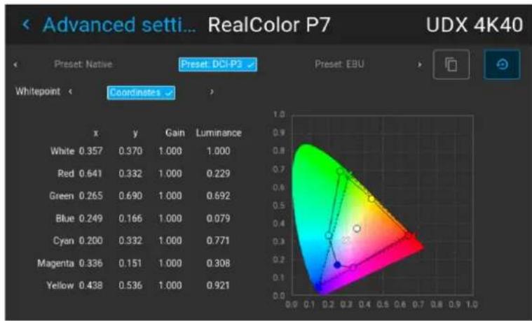
Select one of the pre-defined presets:
-
Standard: A color standard, specifically for UDX projectors.
- Native: Projector native color settings.
• DCI-P3: Color standard for Cinema.
• EBU: European color standard for broadcasting. - SMPTE-C: American color standard for broadcasting.
• Rec. 709: Color standard for high-definition televisions (HDTV).
heatmap
| x | y | Gain | Luminance | | ---- | ----- | ------ | --------- | | White | 0.357 | 0.370 | 1.000 | | Red | 0.641 | 0.332 | 1.000 | | Green | 0.265 | 0.690 | 1.000 | | Blue | 0.249 | 0.166 | 1.000 | | Cyan | 0.200 | 0.332 | 1.000 | | Magenta | 0.336 | 0.151 | 1.000 | | Yellow | 0.438 | 0.536 | 1.000 |Image 5-41 Example of one of the presets, here DCI-P3

Note: After choosing one of the presets, the values of the coordinates can still be altered to your own choosing, similarly to how the custom P7 values can be altered.
Use the Reset icon to return to the default values of the chosen preset.

5.10.3 Setting the output resolution
Location and availability
- Menu: Image > Advanced settings > Output resolution
- Access level: all
- Models: QDX 4K, UDM 4K, UDX 4K, I600 4K, F40 4K, F70 4K, F400 4K, Njord, Hodr, Balder, Bragi
4K-UHD versus Native 4K (N4K)
The native resolution for Barco's standard 4K models is either WQXGA or WUXGA (depending on projector family). The built-in actuator then "boosts" the resolution to 4K in Ultra-High Definition (4K-UHD).
In recent years, Barco has also released projector models where the native resolution is 4K (Native 4K, o' N4K, e. g. F400–N4K). These projector models do not require an actuator to reach 4K and thus don't h access to this menu.
How to determine the desired output resolution
Depending on the main purpose of the projected content, it can be better to choose an alternate resolution. Make your choice according to the following criteria:
- If the main purpose of the projection is HFR video (content with high framerate, e.g. racing games), use the WQXGA / WUXGA output resolution (depending on model). This will disable the actuator and allow content of up to 120 FPS to be ^5 .played.
- If the main purpose of the projection is image (e.g. photographs, movie, or similar purpose), use the 4K UHD output resolution for a sharp 4K image, up to 120 Hz.
- If the main purpose of the projection is text (e.g. spreadsheets, presentations, or similar purposes), use the 4K UHD S output resolution for the for the sharpest possible image, up to 60 Hz..

4K-UHD-S is only available on UDX-4K and UDM-4K projector models, as well as Njord and Hodr
How to choose the output resolution
- In the Advanced settings menu, select Output resolution.
Image
Image 5-42 Advanced settings menu, Output resolution
The Output resolution menu is displayed.
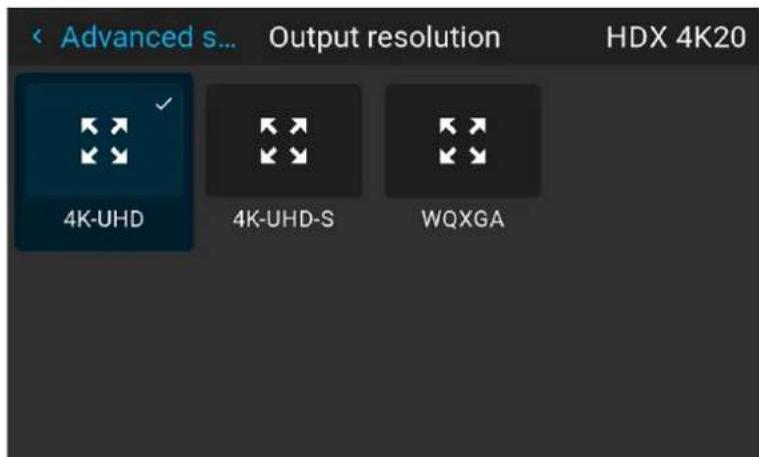
Image 5-43 Example of available output resolutions
- Select the desired output resolution and confirm.
5.10.4 Displaying HDR content
Location and availability
- Menu: Image > Advanced settings > HDR
- Access level: all
- Models: all

PQ
Perceptual Quantizer (PQ) is a non-linear electro-optical transfer function (EOTF) that allows for the display of High Dynamic Range (HDR) content with a luminance level of up to 10 000 cd/m² and be used with the Rec. 2020 color space.
How to properly display HDR content?
HDR content has been mastered specifically for HDR capable displays that are watched in living rooms. These conditions are different from a non-HDR projector and darker cinema-like environments. If the provider HDR content has been mastered with PQ (e.g. HDR10 or Dolby Vision), a few changes can be made in to project the intended mastering on screen.
The projected HDR content depends on the following factors:
- Mastering luminance: This is content-specific and cannot be changed.
- Screen luminance: Every projection screen has a specific luminance, measured in either "nits" (nt) or "foot-Lambert" (fL). Entering this luminance in the projector will adapt the content towards the intended HDR result.
- HDR Boost: A variable "booster" that may amplify or downplay the HDR output.

If no changes are made and there is a mismatch between content mastering and the settings in HDR menu, the projected image can look either washed out or too dark.
How to know if content is HDR encoded?
If the source signal is HDR encoded, an HDR icon will be visible next to the source signal. This icon is both in the Source selection menu, as well as the Dashboard menu.
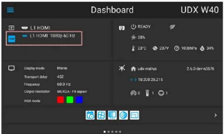
Image 5-44 Example of the HDR icon on the Dashboard menu
How to set the HDR-related parameters?
- Make sure the chosen Gamma Type is set to AUTO. For more info, refer to "Setting the desired gamma type", page 48.
- In the Advanced settings menu, select HDR.
Image 5-45 Advanced settings menu, HDR
The HDR menu is displayed.
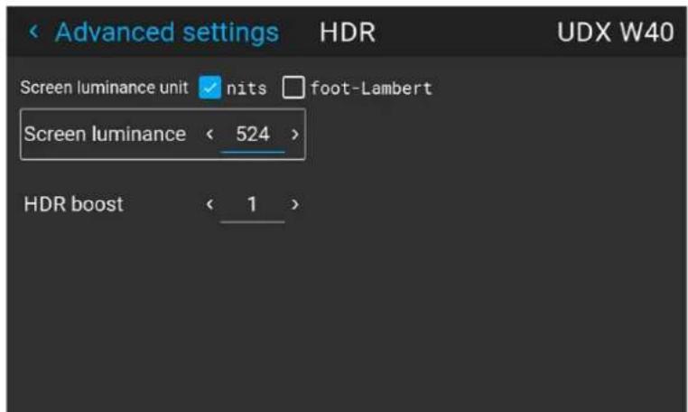
Image 5-46 Example of the HDR menu
- Select the desired Screen luminance unit (nits or foot-Lambert).
- Enter the Screen luminance (which is measured in nits or foot-Lambert).
- Enter the desired luminance unit (nits or foot-Lambert).

Tip: 1 foot-Lambert equals \~3.426 nits. Make sure the selected unit is a match when compared the measured unit.
- Select the Screen luminance.
- Alter the HDR boost if necessary.
• Range: between 0.8 and 1.2
- Default: 1.0
5.10.5 Dynamic contrast
Location and availability
- Menu: Image > Advanced settings > DynaBlack
- Access level: all
• Models: QDX, UDM, UDX, I600
DynaBlack: What is Dynamic contrast?
Projectors rely on contrast to showcase dark scenes or black parts on the projected surface. Whites and I areas are usually projected without issue, but blacks and dark areas are a different matter. With low contr blacks and dark areas appear more grey. The DynaBlack menu helps the accuracy of dark scenes.
Using advanced algorithms, the DynaBlack menu checks the projected content dynamically. Then it adapts the contrast of the light source and the brightness of the content accordingly to create the best possible outcome.

Dynamic contrast works on an individual projector-level, not on group-level. Because of this, it is advised to not use dynamic contrast in a multi-projector setup.
How to set the dynamic contrast?
- In the Advances settings menu, select DynaBlack.
Image 5–47
The DynaBlack menu is displayed.
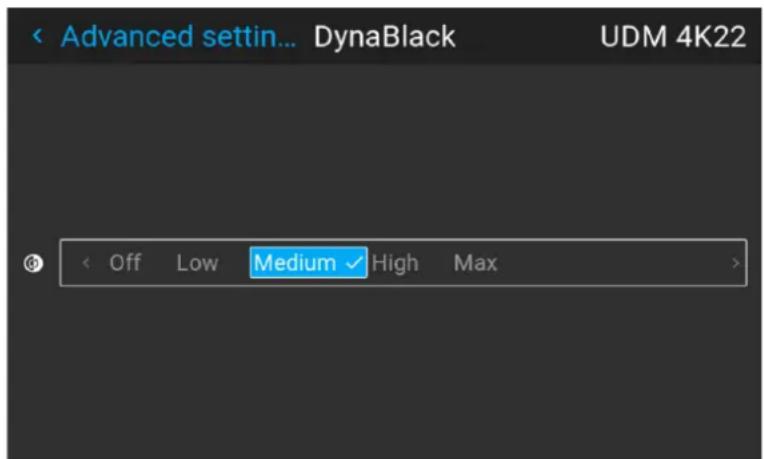
Image 5-48 Example of the DynaBlack menu
- Select the desired dynamic contrast setting, or leave the default on (medium).
The result will slowly become visible.

Do not panic if there isn't a visible change after a few seconds. Each change in the dynamic command menu has an impact on the light source, thus these changes will only become visible over time.
5.10.6 BrilliantColo™
Location and availability
- Menu: Image > Advanced settings > BrilliantColor™
- Access level: all
• Models: I600, FL40, FS40, F70, F400, Bragi, Balder
About BrilliantColo™
The BrilliantColor™ mode has an effect on the color rendering. Depending on the chosen option, BrilliantColor™ may have an effect on color intensity, brightness, smear effect and flicker effects.
BrilliantColor™ options
The options available in the BrilliantOcbenu depend on the projector model.
The following is the full list of available options. For an overview of what options are available for the cu projector model, see “BrilliantCoMo and Smear reduction availability”, page 245.
- Off: BrilliantColor™ is turned off. Only primary colors are generated by the light source.
• Video: Setting for the best possible color reproduction of video content. - Video Bright: Setting optimized for TV content used in brighter “living room” type of setups.
- Native: Setting for maximum brightness
• Film: Setting optimized for film reproduction to give best possible color reproduction. - Gaming: Setting optimized for gaming. Low smear, but keeps a good performance regarding flicker effects in the blend zone.
- Graphics: Setting optimized for computer presentation. Greatly reduces flickering in blend zones, while keeping a good smear performance.
• High Brightness: Setting for highest brightness options. - Vizsim: Setting used for the best possible color reproduction.
- Vizsim Bright: Setting for balancing color reproduction and brightness level.
- Vizsim Bright Plus: Setting for higher brightness level while keeping color reproduction at a good level.
- Vizsim Bright Optiblend: Setting for reducing flickering effects in the blend zone, while still having a very good smear performance.
- Vizsim Bright Optismear: Setting optimized for smear performance, while still having a good performance regarding flicker effects in the blend zone.
How to select a BrilliantC01nonode
- In the Advanced settings menu, select BrilliantColor ^TM .
Image 5-49 Advanced settings menu, BrilliantColor
The BrilliantColo™ menu is displayed.
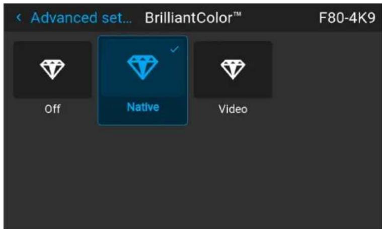
Image 5-50 Example of the BrilliantColmenu
- Select the desired BrilliantColMode from the available listing and confirm.
5.10.7 Smear reduction
Location & availability
- Menu: Image > Advanced settings > Smear reduction
- Access level: all
• Models: FL40, FS40, F70, F400, Bragi, Balder
About smears and smear reduction
A smear is a phenomenon that typically occur when objects in the picture moves in high speed over the screen. It appears like there is a "tail" behind the object, or a lag in the moving parts of the picture.
In order to avoid this the Smear Reduction Process™SRP developed. This feature reduces smear, by adding dark time to the projected image.

Do take in mind that smear reduction comes with the cost of a slightly reduced brightness (depending on the amount of smear reduction).
Smear reduction options
The available options for Smear reduction depend on projector mode and chosen BihardColor
The following is the full list of available options. For an overview of what options are available for the cu projector model, see "BrilliantCoM and Smear reduction availability", page 245.
- SRP ^TM Off
- SRP ^TM 12.5%
- SRP ^TM 25%
- SRP ^TM 37%
- SRP ^TM 37.5%
- SRP TM 50%
- SRP ^TM Half
- SRP ^TM Half BSI
- SRP ^TM Half Plus
• SRP ^TM Half Plus BSI - SRP TM Full
• BSI (Black Sub Frame Insertion)
How to activate smear reduction
- In the Advanced settings menu, select Smear reduction.
Image 5-51 Advanced settings, Smear reduction
The Smear reduction menu will be displayed.
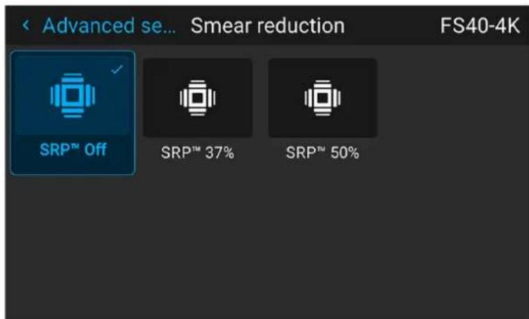
Image 5–52 Example of the Smear reduction menu
- Select the desired smear reduction option from the available listings and confirm.
5.10.8 Cropping the image to 16:9 centered
Location and availability
- Menu: Image > Advanced settings > 16:9 Centered
- Access level: all
• Models: Njord, Hodr, Balder, Bragi

For Cinemascope Residential projectors, this feature is replaced with the more advanced Cropping menu. For more info, see "Cinemascope - Cropping the image", page 56.
About the 16:9 Centered functionality
Barco residential projectors project in 16:9 aspect ratio by default. However, when content in 16:9 aspect r is projected on a Cinemascope screen, the lower and upper part of the picture will go outside the screen known as “content overshoot”).
When the 16:9 Centered function is enabled, the picture will center the image and crop the content to fit the height of the screen. Therefore, in order to keep the aspect ratio, the image will not exploit the entire sc width.
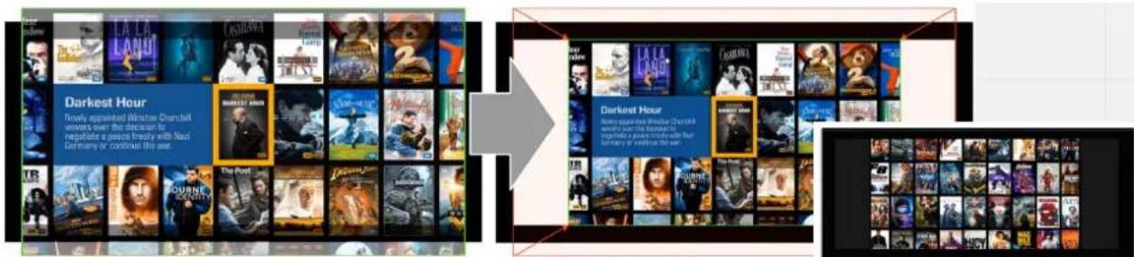
Image 5–53 Example of 16:9 content on a Cinemascope screen without (left) and with (right) the 16:9 feature enabled

Activating the 16:9 Centered preset will neglect all other warping options.
How to activate a centered 16:9 image
- In the Advanced settings menu, enable the 16:9 Centered slider.
Image 5–54 16:9 Centered is off Image 5–55 16:9 Centered is on
The projected image will be cropped and centered to a 16:9 aspect ratio.
5.10.9 Night vision
Location and availability
- Menu: Image > Advanced settings > Night vision
- Access level: all
• Models: FS40, FS70, FS400
About
It is important that both the night vision goggles as well as the projector have their daylight image and the vision image on an identical channel (e.g. daylight on DisplayPort 1 for both goggles and projector).
However, if a different type of goggles are used, or somebody made a mistake during installation, the Swap channels option in the Night vision menu can be used to quickly correct this without requesting a service technician or installer to dismantle the simulation booth.
How to swap channels
- In the Advanced settings menu, select Night vision.
Image 5–56 Advanced settings menu, Night vision
The Night vision menu will be displayed.
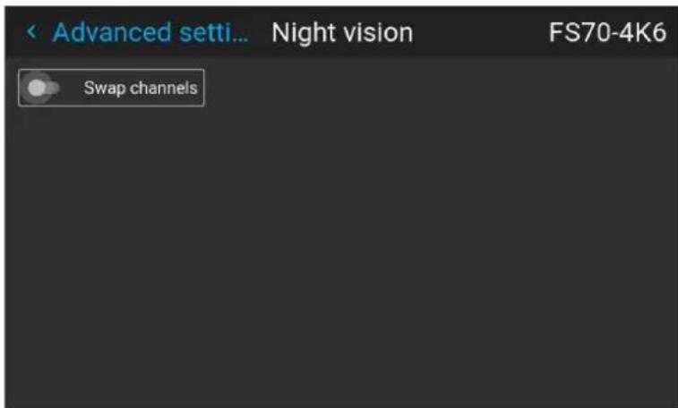
Image 5–57 Example of the Night vision menu
- Enable or disable the Swap channel function.
Installation
6
6.1 Configuring the projector position....74
6.2 Configuring optics....82
6.3 Scaling modes....91
6.4 Warping 93
6.5 Blending & masking 107
6.6 Illumination 119
6.7 IR illumination – Night vision functionality 121
6.8 3D projection....124
6.1 Configuring the projector position
Note regarding the position menu
On Pulse 2.3 and later, several software features related to the positioning of the projector have been gro together in the Position submenu.
When consulting these features in older software versions, these can be found directly in the installation menu.
6.1.1 Orientation
Location and availability
- Menu: Installation > Position > Orientation
- Access level: all
- Models: all
What can be done?
The way of physical installation of the projector can be defined to the projector.
The following installation are possible:
- Desktop front: Projected image will not be flipped or mirrored.
- Desktop rear: Projected image will be flipped horizontally (left side switches to the right side).
- Ceiling front: Projected image will be flipped vertically (top side switches to the bottom side).
- Ceiling rear: Projected image will be flipped both vertically and horizontally.
- Auto front: The tilt sensor will detect if the projector is desktop or ceiling mounted and will project a readable image accordingly.
- Auto rear: The image will be flipped horizontally. The tilt sensor will detect if the projector is desktop or ceiling mounted and will project a readable image accordingly.
How to set the correct orientation
- In the Position menu, select Orientation.
Image 6-1 Position menu, Orientation
The Orientation menu is displayed.
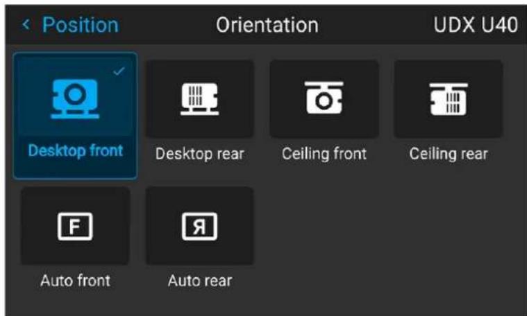
Image 6-2 Example of the orientation menu
- Select the desired projector orientation mode and confirm.
The projected image will be flipped according to the chosen orientation.
6.1.2 Laser ranging
Location and availability
- Menu: Installation > Position > Laser ranging
- Access level: all
• Model: QDX, UDM, UDX - Requirements: Distance meter and camera kit

The Laser ranging menu will only be enabled when the Camera feature is enabled in the Security menu. For more info, see "Security - Enable camera preview", page 204.
What can be done?
When the optional distance meter and camera kit is installed on the projector, the laser source can be used to measure the distance between the front of the projector and the projected surface. Use this to fine-tune the position of the projector.
The measured distance can also be stored as a reference value. Using this, the current distance can be verified at certain time intervals (e.g. during startup). When the projector is changed from its original referee position, a notification will be triggered.

Take into account that while a laser ranging session is active, the projected image will be off. Th have no interference between laser pointer and projected image. Instead, a red border will be projected giving the outline of where the projected image should be.
How to measure the distance between projector and screen?
- In the Position menu, select Laser ranging.
Image 6-3 Position menu, laser ranging
The Laser ranging menu will be displayed.
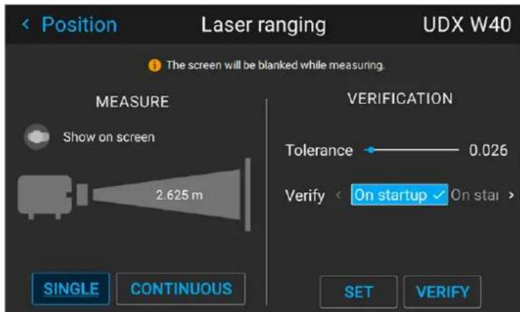
Image 6-4 Example of the laser ranging menu
- Enable the Show on screen slider to project the distance being measured while performing a laser ranging session.
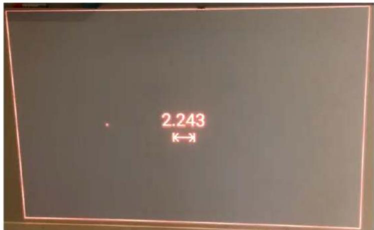
Image 6–5 Example of projected image during laser ranging session with measurement on screen
- For a single laser ranging calculation, press Single. This will continue the laser for 30 seconds straight.
or
For a continued laser ranging (e.g. when fine-tuning the position of the projector), press Continuous instead.

Tip: If pressed, the Continuous button will be replaced with a Stop button. Press the Stop button to stop the measurement.
Take note that when Stop is pressed, it will take a few more seconds to finish up the measure. The measurement is only completed when the regular source image is returned to the screen.
- Press Set to store the measured distance as a reference value.
If a reference distance was already stored, a message will be prompted asking to confirm to overwrite existing reference.

By default the measurement is in meters. To measure in feet instead, change the measurement system in the settings menu. For more info, refer to "Units (measurement) system setup", page 168.
How to verify the measured distance?
Once a measured reference distance has been stored in the projector, the currently measured distance car verified with the stored reference distance as follows:
- Set a Tolerance (in meters by default). Use the slider to set the desired tolerance between reference distance and measured distance.
- Set on which moment the projector will verify the measured distance. Choose one of the following:
- On startup
- On standby
- Off
If the verified distance ends up being different compared to the set reference distance, a notification will be prompted and the measured distance will be marked red.
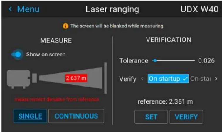
Image 6–6 Example of the measured distance being different than the set reference distance
6.1.3 Tilt sensor
Location and availability
- Menu: Installation > Position >> Position.
- Access level: All
- Models: All
When to use the tilt sensor menu
The projector has a built-in tilt sensor that detects the angle at which the projector is mounted. In a situ where the projector needs to be fine-tuned to achieve a picture at a specific angle (e.g. perfectly level, perfect fit in a multi-projector setup), the tilt sensor menu can be used as a visual aid when adjusting the projector feet, rigging frame or other used mounting mechanisms.
About Pitch & Roll
The Pitch and the Roll is indicated in degrees.
Pitch tilt: A positive value for the Pitch means that the projector is projecting upwards when compared to the beam axis. A negative value means the projector is projecting downwards.
Roll tilt: Seen from the rear of the projector, a positive value means that it rolls to the right (clockwise). A negative value means the projector has rolled to the left (counterclockwise).
How to read the tilt sensor values
- In the Position menu, select Tilt sensor.
Image 6-7 Position menu, Tilt sensor
The Tilt sensor menu is displayed.
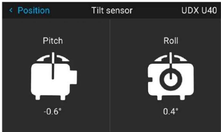
Image 6-8 Example of the tilt sensor menu

If the tilt sensor isn't working correctly (e.g. when compared to a level), the sensor can be calibrated. For more info, see "Service - Tilt sensor calibration", page 214.
6.1.4 Manipulating the rigging frame, center position
Location and availability
- Menu : Installation > Position > Center motorized frame.
- Access level: all
• Models: QDX, UDM, UDX, F70 - Requirements: Motorized rigging frame
Using the front XLR connector on QDX, UDX and UDM
When using a motorized frame on QDX, UDX and UDM, the motorization is connected with the front XLR connector.
When using the front XLR connector, make sure it is enabled and powered to 24V. For more info on how power the XLR connector, see “Controlling the front XLR connector”, page 182.

CAUTION: Do not enable the front XLR connector at 0V while the motorized frame is connected. Having the motorized frame connected to the projector while the connector is active and set at 0V will cause connection issues. If the frame is not used, disable the front XLR connector. Do not ju place the connector at 0V.
A future version will resolve this issue.
How to return the motorized frame to center position?
- In the Position menu, select Center motorized frame.
Image 6-9 Lens menu, Center motorized frame
A confirm action dialog box will be prompted.
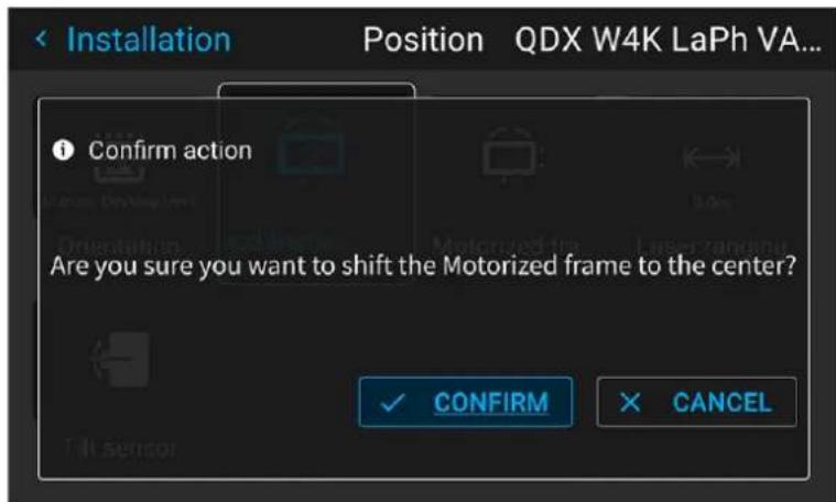
Image 6-10 Example of the Center motorized frame action prompt
- Confirm to reset the frame to its center position.

Note: Wait until the frame motors have stopped before doing other actions.
6.1.5 Manipulating the motorized rigging frame
Location and availability
- Menu : Installation > Position > Motorized frame.
- Access level: all
• Models: QDX, UDM, UDX, F70 - Requirements: Motorized rigging frame
Using the front XLR connector on QDX, UDX and UDM
When using a motorized frame on QDX, UDX and UDM, the motorization is connected with the front XLR connector.
When using the front XLR connector, make sure it is enabled and powered to 24V. For more info on how power the XLR connector, see "Controlling the front XLR connector", page 182.

CAUTION: Do not enable the front XLR connector at 0V while the motorized frame is connected. Having the motorized frame connected to the projector while the connector is active and set at 0V will cause connection issues. If the frame is not used, disable the front XLR connector. Do not ju place the connector at 0V.
A future version will resolve this issue.
How to manipulate the rigging frame?
- In the Position menu, select Motorized frame.
Image 6-11 Position menu - Motorized frame
The Motorized frame menu is displayed.
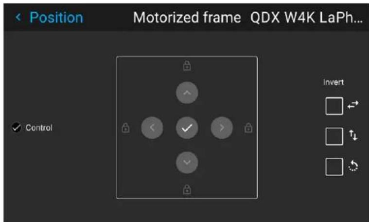
Image 6-12 Example of the Motorized frame menu
-
To enable inverted controls, make sure the checkboxes are selected next to the invert icons:
-
Invert horizontal
- Invert vertical
-
Invert rotation
-
Press the OK key or button to activate the vertical frame shift motors.
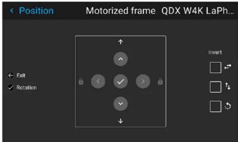
Image 6-13 Example of vertical frame shift
- Use the ▲ or ▼ button to shift the rigging frame (image) in vertical direction.
- Press the OK button to shift between shifting and rotation.
The frame rotation menu is displayed.
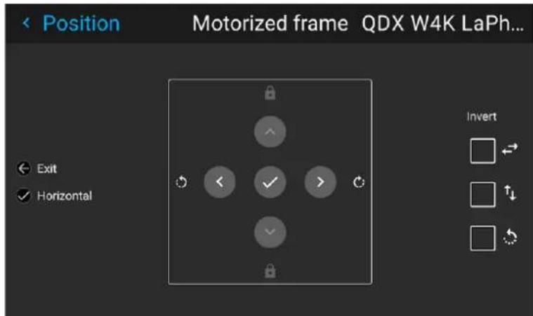
Image 6–14 Example of frame rotation
-
Use the ◀ or ▶ button to rotate the rigging frame (image) either clockwise or counterclockwise.
-
Press the OK button to shift between rotation and horizontal shifting.
The horizontal shift menu is displayed.
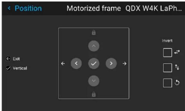
Image 6-15 Example of the horizontal frame shift
-
Use the ◀ or ▶ button to shift the rigging frame (image) in horizontal direction.
-
Confirm with the OK button to return to the vertical frame shift menu, or use the Menu back button to return to the Position menu.
6.2 Configuring optics
Note regarding the Optics menu
On Pulse 2.4 or later, the Lens submenu has been renamed into the Optics menu.
While the name has changed, the functionality of the menu remains the same.
6.2.1 Optical zoom and focus
Location and availability
- Menu: Installation > Optics > Zoom focus
- Access level: All
- Models: all
- Requirements: Motorized lens
About the Zoom and focus menu
When a motorized lens is mounted in the projector this menu can be used to fine-tune the projected image
How to configure zoom and focus
- In the Optics menu, select Zoom focus.
Image 6–16 Optics menu, Zoom & focus
The Zoom focus menu will be displayed.
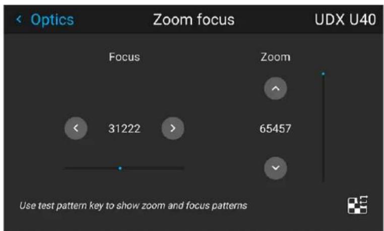
Image 6-17 Example of the zoom and focus adjustment menu
- Press the test pattern key to enable a test pattern.
- Use the ▲ or ▼ key to zoom the lens in or out and confirm.
- Use the ◀ or ▶ key to focus the lens to far or near and confirm.
6.2.2 Configuring lens shift
Location and availability
- Menu: Installation > Optics > Shift
- Access level: All
- Models: all
What can be done?
The image can be optically shifted by using the vertical and horizontal lens shift.

Optical lens shift is only possible when the used lens has been fully calibrated. For more information, see "Lens calibration", page 194.
When a lens shift beyond what is possible with the optical shift is desired, Alternatively a digital lens shift also be performed. This digital shift will occur on the DMD, rather than the lens holder. So take into account that this additional shift is minimal and restricted to the limits of the chip used. For more info on digital I shift, see "Digital zoom and shift", page 53.

Digital shift and zoom is not available for High End Residential devices.
Vertical and Horizontal Shift
- In the Optics menu, select Shift.
Image 6–18 Optics menu, lens shift
The Shift menu is displayed.
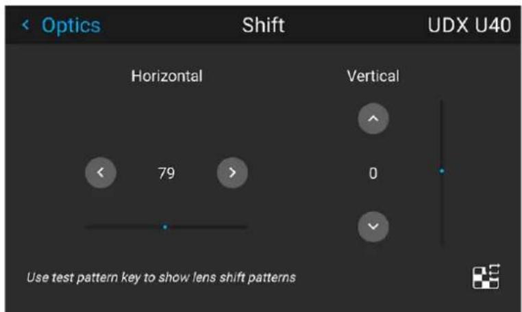
Image 6–19 Example of the lens shift menu
- Press the test pattern key to enable a test pattern.
- Use the ◀ and ▶ keys to shift the lens (image) in horizontal direction.
- Use the ▲ and ▼ keys to shift the lens (image) in vertical direction.
6.2.3 Configuring dynamic focus on UST lens
Location and availability
• Menu: Installation > Optics > Dynamic focus
- Access level: all
• Models: QDX, UDM, UDX, Njord, Hodr
- Requirements:
- Pulse 2.6 or later
- UST lens R9801661 installed
- Light source must be on

At this moment, the new Dynamic focus only works on UST lens R9801661. This feature may be rolled out on more lenses in the future.
About dynamic focus
Due to the design of TLD+ lenses and ultra-short throw lenses (UST lenses), these type of lenses tends heat up over time when used in projectors. This has the side-effect of a slight shift in focus between the its cold state and the lens in its heated state. This is labeled focus drift or thermal focus drift.
Dynamic Focus is an algorithm which automatically adjusts focus (and zoom), which compensates for this thermal focus drift.
A set of reference points is required for this version of focus drift to work. Each point is capturing a more time when the projected image was perfectly focused. This data is used by the algorithm to maintain focus the projected content changes.
About the reference points
Each reference point exists out of a "short value" and a "long value".
The short value looks at the content (pixel values, resolution and illumination power) at rate if 20 times p-second and calculates what “focus factor” is required for the current content on a scale of 1-100 (in percentage). It recalculates a new Short Value every five seconds to get an as accurate as possible short focus factor.
The long value uses each generated “short value” at a rate of 50 times per second and uses this data determine the long-term “focus factor” on a scale of 1-100 (in percentage).
Both long and short values combined create a single coordinate for the focus drift compensation. By using set of 3-10 of these coordinates, the algorithm will determine the best possible focus factor for the lens.
Guidelines
Take into account the following guidelines:
• Reference points can only be set after the projector is in Ready or ON mode for 90 minutes or more.
Note: Rebooting the projector or setting it to Standby mode will reset this 90 minute timer.
- A minimum of three reference points is required in order to enable dynamic correction.
• To improve accuracy, up to 10 reference points can be added.
- Ensure that the reference points cover varied content (e.g. bright/white-like content, very colorful content and dark content). The more different cases are taken into consideration, the better the dynamic focus algorithm will work.
- Avoid setting reference points with similar short and long percentages, as this will reduce the effect of dynamic focus algorithm.
- Setup specific. Reference points are linked to installation setup and used lens. If these change, a new set of reference points will have to be defined.
How to add reference points?
- In the Optics menu, click Dynamic focus.
Image 6–20 Optics menu, Dynamic focus
The Dynamic focus menu is displayed.
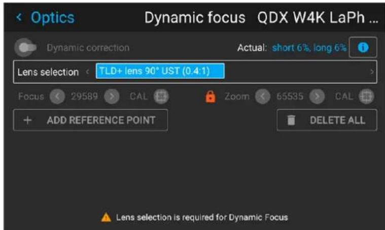
Image 6-21 Example of the Dynamic focus menu at the start.
- Select the desired lens from the list and confirm.
The Calibrate icon will become enabled.
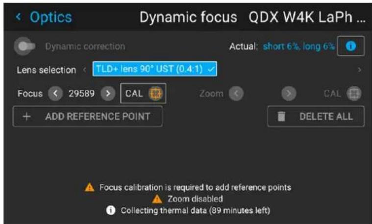
Image 6–22
- Click CAL.

Note: The first three steps can be completed while you are still waiting for the lens to have fully warmed up.
The lens will be calibrated.
If the lens has fully warmed up and is calibrated, the + ADD REFERENCE POINT button will become enabled.
- Add a reference point as follows:
a) Project desired content that is reflective of the end result (e.g. movie, static image, test pattern).
b) Wait until the actual reference data (short and long percentage) become stable.
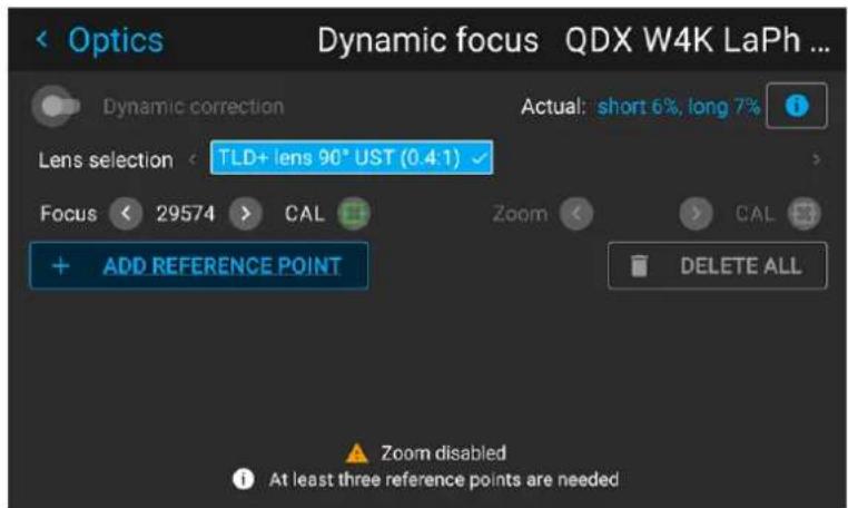
Image 6-23 Example of the menu, with the actual percentages visible in the top right corner
c) Correct focus and zoom until you get the desired image on screen. For more info on correcting zoom and focus, see "Optical zoom and focus", page 82.
d) Click + ADD REFERENCE POINT
The point is added in the list.
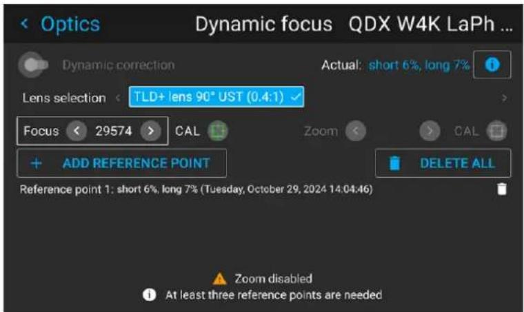
Image 6-24 Example of the menu with one reference point created
- Repeat the previous step for various content types until at least three reference points have been made. Once at least three reference points have been made, the Dynamic correction slider will become enabled.
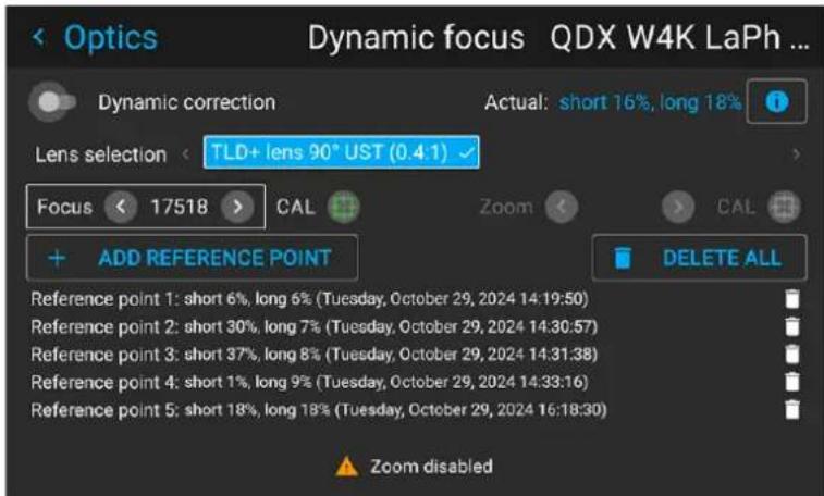
Image 6-25 Example of the menu with a set of various reference points
- Enable the Dynamic correction slider.
All options in the menu will become disabled.
The algorithm will start working on the projected content.
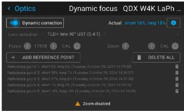
Image 6-26 Example of the enabled Dynamic correction
6.2.4 Shift to center
Location and availability
- Menu: Installation > Optics > Shift to center
- Access level: all
- Models: all
What can be done?
The lens shift can be forced back to the center position by selecting Shift to center.
How force a lens to center position
- In the Optics menu, click Shift to center.
Image 6-27 Optics menu, Shift to center
A Confirm action dialog will be prompted.
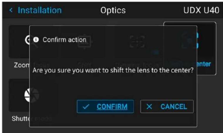
Image 6-28 Example of the Shift to center action
2. Press the CONFIRM button.
The lens will calibrate itself and return to the center position.
6.2.5 Configuring the Iris
Location and availability
- Menu: Installation > Optics > Iris
- Access level: all
• Models: FL40, FS40, F70, F400, Bragi, Balder
About the iris
Iris controls the contrast and focus depth of the image, and will also have an impact on the output light.
Decreasing the iris opening will increase contrast and image depth, at the same time as it decreases the output light.
The projector has two irises; one in the lens, and one in the illumination path. Both irises share a similar function, albeit with a small difference.
Lens iris
Located in the lens, and will increase the contrast and depth of the focus area when used. Will also have effect of the output light
Illumination iris
Located in the illumination path, and has less, but still an effect on the contrast and the depth of the focal area, but will to a greater extent have an effect on the amount of output light.
How to adjust
- In the Optics menu, select Iris.
Image 6–29 Optics menu, Iris
The Iris menu is displayed.
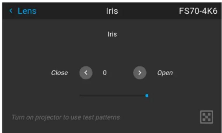
Image 6–30 Example of the Iris menu
-
Use the arrow keys to adjust Iris until preferred rendering is obtained. The numeric value in the menu indicates the degree of opening of the iris.
-
Value = 0 >> Iris fully opened (iris feature not active).
- Value > 0 >> Iris opening decreases (iris feature active)
6.2.6 Shutter mode
Location & availability
- Menu: Installation > Optics > Shutter mode
- Access level: all
• Models: UDM, UDX
About the shutter
All projectors have a shutter. This can be either a mechanical shutter (on W and U models), or an electric shutter (on 4K models). When the shutter is closed, the light source will turn off. When the shutter is open the light source will turn on.
When the light source turns on again, the laser banks have to turn on sequentially, with different types of banks having a different startup time. This may lead to a short timeframe where the colors of the project image are not displayed in an optimal fashion.
The Pulse OSD software provides a configuration option for the behavior of the electronic shutter:
- Optimal colors: The projector will wait to open the shutter until all laser banks are fully operational and the colors can be displayed as intended. The time this takes will vary depending on projector type, but it is minimum two seconds.
- Fast transitions: The shutter opens immediately and the image will be projected, regardless of laser bank status. This will cause the projected colors to be slightly "off" for a few seconds until all laser banks are operational.
How to set shutter mode
- In the Optics menu, select Shutter mode.
Image 6-31 Optics menu, Shutter mode
The Shutter mode menu will be displayed.
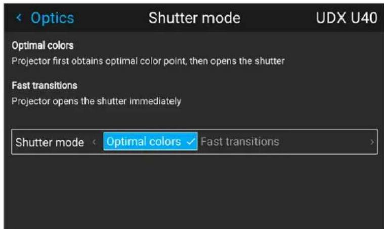
Image 6-32 Example of the Shutter mode menu.
Installation
- In the Shutter mode menu, select the desired Shutter mode and confirm.
6.3 Scaling modes
Location and availability
- Menu: Installation > Scaling
- Access level: all
- Models: all
About scaling modes
While the default mode of projection is to fill the screen while respecting the aspect ratio (fill aspect), it is possible to stretch the image in a different way. Choose one of the following scaling methods:
| Scaling Mode | Explanation Example image | 6 |
| Fill aspect Default scaling mode. Stretches the image to the native resolution of the DMD, while respecting the original aspect ratio. | 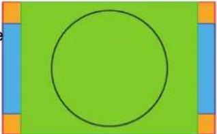 | |
| 1:1 An exact rendering of the source signal, which may be smaller than the native resolution | 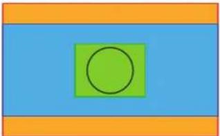 | |
| Fill screen Fills the screen to the screen size defined in the Scr Size menu, while respecting the original aspect rat For more info on adjusting the Screen Size menu, “Warping - Screen size”, page 93. | 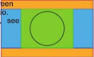 | |
| Stretch This mode stretches the image to the screen size defined in the Screen Size menu, while ignoring the original aspect ratio. For more info on adjusting the Screen Size menu, see “Warping - Screen size”, 93. | 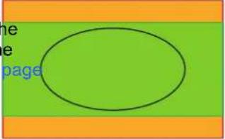 | |
Setting a scaling mode
- In the Installation menu, select Scaling.
Image 6-33 Installation menu, scaling
The scaling mode menu will be displayed.
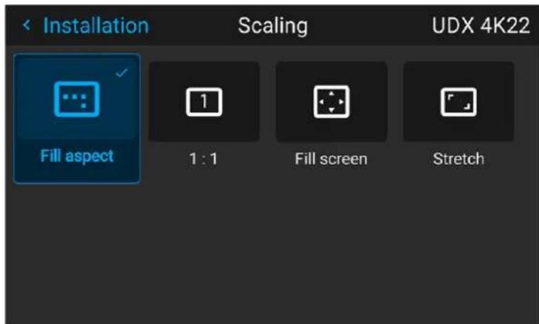
Image 6-34 Example of the scaling mode menu
- In the Scaling menu, select the desired scaling mode and confirm.
6.4 Warping
About warping
Image warping is the process of digitally manipulating an image to compensate for the distortion of the sc Consequently, it can also be used to generate an image with irregular shape.
While an image can be transformed in various ways, pure warping doesn't affect the colors.
6.4.1 Warping - on/off
Location and availability
- Menu: Installation > Warp
- Access level: all
- Models: all
About warping on/off
By toggling between on and off the warping functionality can be enabled or disabled.
How to toggle
- In the Warp menu, click Warp to toggle between On and Off.
Image 6–35 Image 6–36
If any warp has been configured, the projected image will be warped accordingly.
6.4.2 Warping - Screen size
Location and availability
- Menu: Installation > Warp > Screen size
- Access level: All
- Models: All
About (Warp) screen size adjustment
If the used source aspect ratio is different than the projector aspect ratio (e.g. source is 16:9 and projected 16:10), then black bars will be projected. In this example case a black bar on top and bottom of the image be projected. The warp area contains not only the image information but also the black bars.
If the projector needs to be positioned specifically (e.g. the active left top corner exactly on the screen using corner warp), then it is very hard to do that when moving the black left top corner and not having control the exact position of image left top corner. By moving the outline of the warp screen size to the active information, the corner points of the warp area are now exactly on the corner points of the active image information and makes warping much easier.
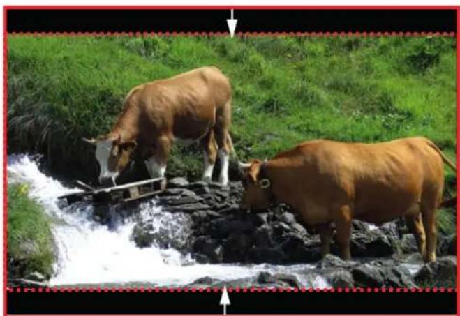
natural_image
Two brown cows grazing on a rocky stream surrounded by green grass (no text or symbols visible)Image 6–37 Warp outline example
Using the screen aspect ratio presets
- In the Warp menu, select Screen size.
Image 6–38 Warp menu, screen size
The Screen Size menu is displayed.
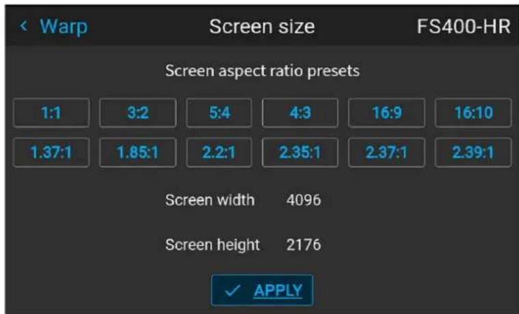
Image 6-39 Example of the screen size menu
- Click on one of the predefined presets for the screen aspect ratio.
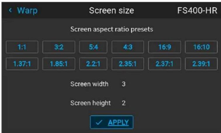
Image 6-40 Example of the screen size menu, with preset "3:2" selected.
The selected ratio is filled out next to Screen width and Screen height.
3. Click Apply.
How to adjust the image with pixels?
- In the Warp menu, select Screen size.
Image 6-41 Warp menu, screen size
The Screen size menu will be displayed.
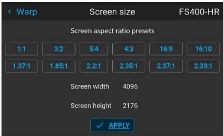
Image 6-42 Example of the screen size menu
-
Select either Screen width or Screen height.
-
Set the new value to shrink either the width or height of the warp outline so that the outline is equal with the active source.
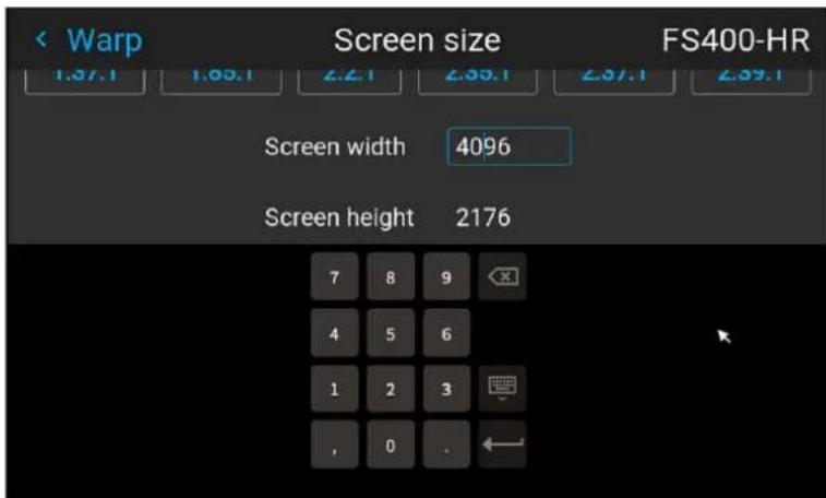
Image 6-43 Example of the Screen size menu, editing the screen width

Tip: A red border will be projected along with the current image. The border is a visual tool, showing the result of the adjusted outline.
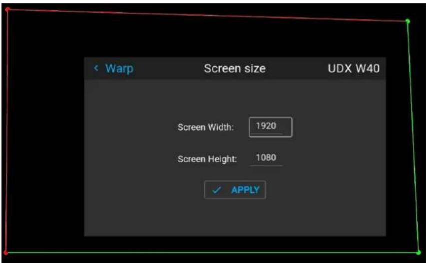
Image 6-44

Tip: The value can also be entered by the numeric keys on the remote control. Press * to deliver existing numbers, and enter the new value by the numeric keys.
4. Click Apply.
6.4.3 Warping - 4 corners adjustment
Location and availability
- Menu: Installation > Warp > 4 corners
- Access level: all
- Models: all
About 4 Corners adjustment
4 corner adjustment is typically used when the mechanical installation of the projector prevents it from pair perpendicularly at the screen. For example, the projector overshoots the screen and 4 corner adjustment is needed to pull the projected image corners back into the screen.
Some visual examples:
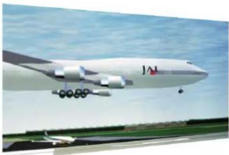
natural_image
Exterior view of a large cargo aircraft (JAL) flying over an airport runway under a clear sky, with no visible text or symbols on the aircraft body.Image 6-45 4 corner adjustment
natural_image
Exterior view of a large Airbus IAC aircraft in flight with landing gear deployed, against a clear sky (no visible text or symbols)How to adjust the image?
- In the Warp menu, select 4 Corners.
Image 6–46 Warp menu, 4 corners
The 4 corners menu is displayed.
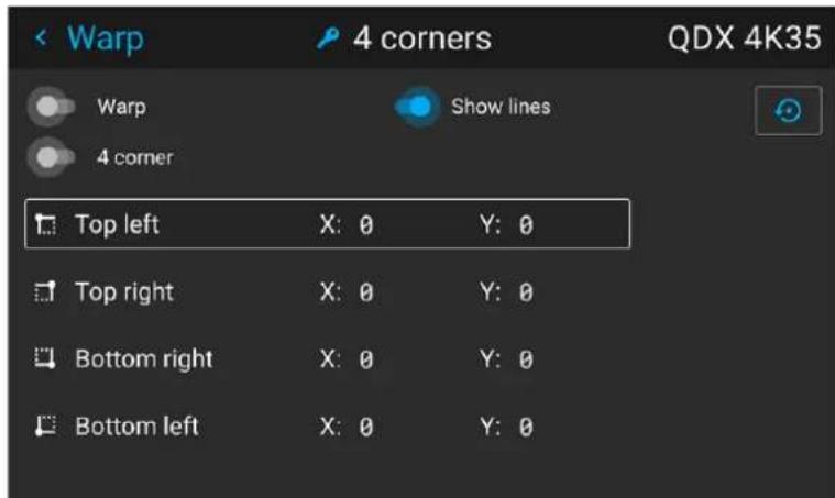
Image 6-47 Example of the 4 corners menu
- Enable the 4 corner slider.
- To have a visual representation of what the warp will look like, enable the Show lines slider.
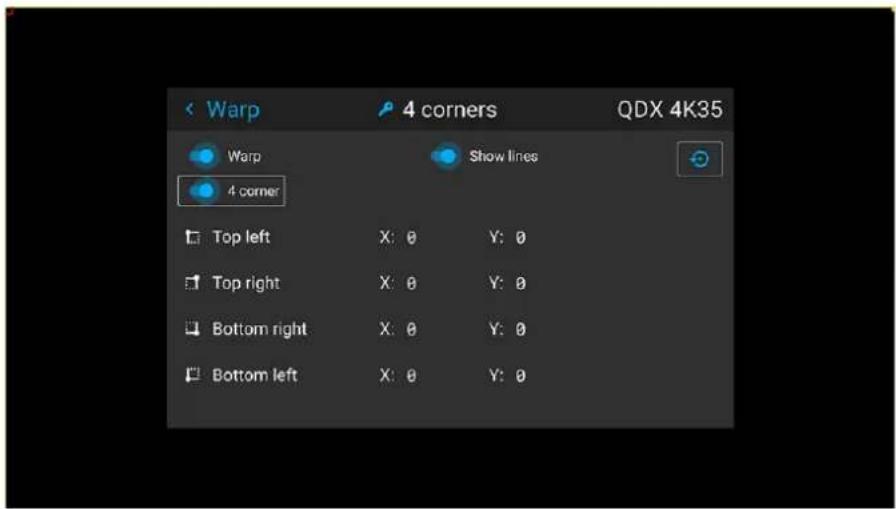
Image 6-48 Example of 4 corners warping menu, with helper lines active on the edges of the screen
-
To set warping on one of the four corners, select one of the four corners and confirm.
-
Set the desired X and Y coordinates for this corner as follows:
-
Use the left and right arrow keys to set the X coordinate and confirm.
- Use the up and down arrow keys to set the Y coordinate and confirm.
After confirming, the helper lines for that corner will jump to the entered XY coordinate (if helper lines enabled).
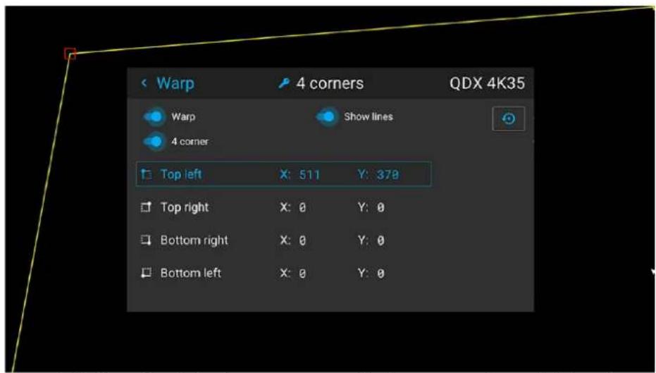
Image 6-49 Example of the 4 corners menu, with 4 corner warping and helper lines enabled
- Repeat the previous steps for each subsequent corner, until all corners are warped in the desired position.

To reset the 4 corner adjustments, select the Reset icon in the top-right corner and confirm.
6.4.4 Warping - Bow
Location and availability
- Menu: Installation > Warp > Bow
- Access level: all
- Models: all
About bow adjustment
A bow distortion can be adjusted so that a normal image is displayed.
- Positive adjustments introduce more outside bow distortion.
- Negative adjustments introduce more inside bow distortion.
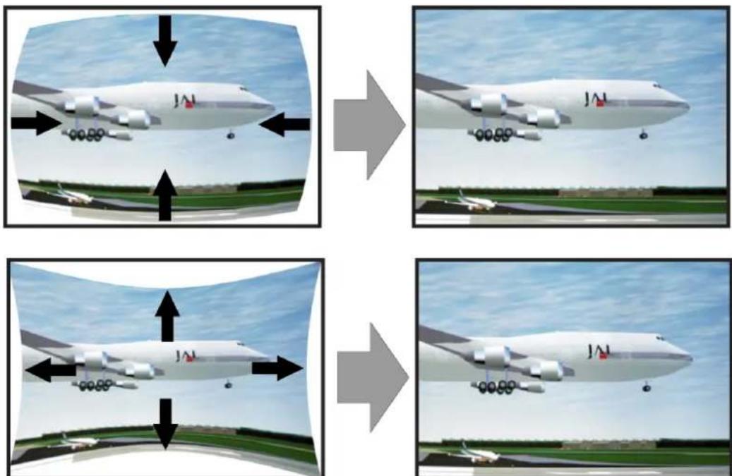
Image 6–50 Bow distortion
Angle and linearity (length) in bow warping
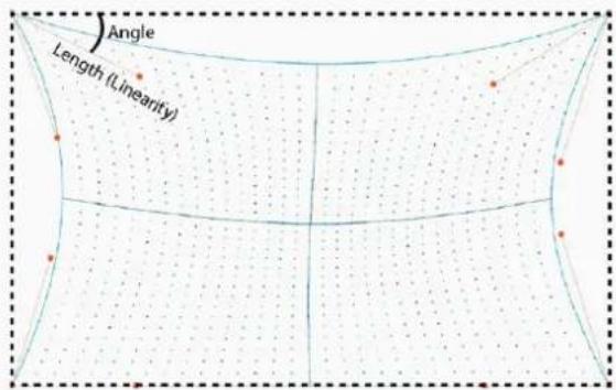
Image 6–51
Symmetric bow correction
- In the Warp menu, select Bow and confirm.
Image 6-52 Warp menu, Bow
The Bow menu will be displayed.
Installation
-
Enable the Bow and Warp sliders.
-
To perform a symmetric adjustment, enable the Symmetric slider.
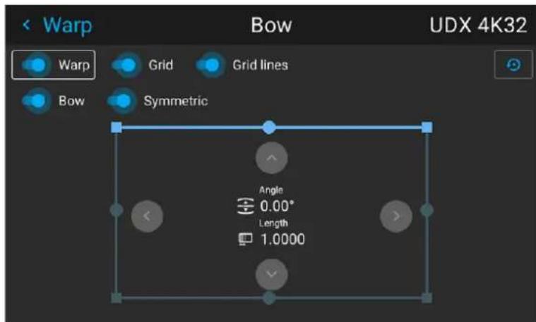
Image 6–53 Both the Bow and Symmetric sliders are set to on
- Enable the following sliders if you want certain aids active:
Grid: Projects colored dots on the screen in the warped shape that is currently active
▶ Grid lines: Projects the outlines of the projected surface grid with the corners in the desired angle.

Note: The Grid and Grid lines sliders are only available from Pulse 2.6 and later.
- Use the arrow keys to select the helping lines that represent the picture and confirm.
The helping lines that represent the projected picture are now colored blue, while the others are colored white.
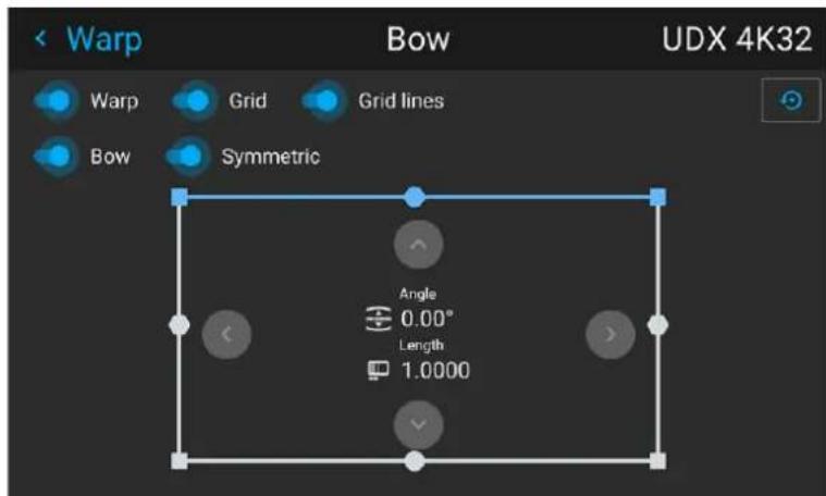
Image 6-54 The upper line is colored blue, the other sides are colored white
- Use the arrow keys to select the side of the picture that needs a correction and confirm.
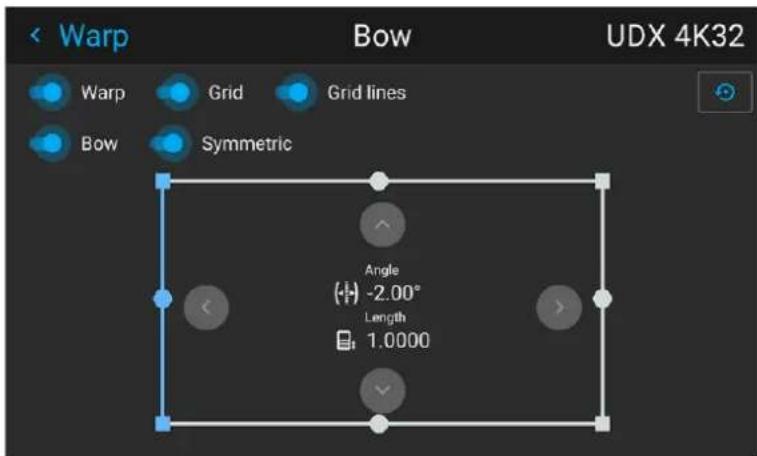
Image 6–55 Symmetric bow correction
- Use the arrow keys to select the side of the picture that needs a correction and confirm.
- Use the arrow keys to adjust the angle and linearity (length) of the vectors. Press enter to confirm and switch between angle and length.

Tip: The angle is adjusted by using the up and down arrow keys. The linearity is adjusted by using the left and right arrow keys.
The correction will occur symmetrically on each side of the center of the highlighted side.
- Repeat this step for all sides of the picture that has to be corrected, until the desired transformation has been achieved.
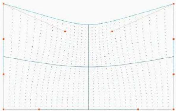
natural_image
Pure geometric diagram with grid lines and dots, no text or symbols presentImage 6–56 Example of a symmetric bow correction
Asymmetric bow correction
- In the Bow menu, enable the Bow slider and disable the Symmetric slider.
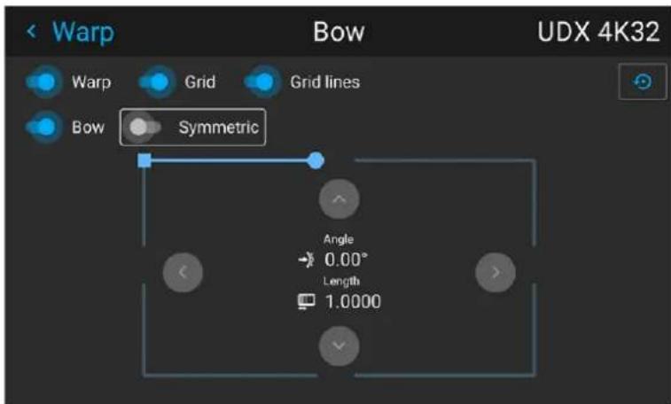
Image 6-57 Example of the bow menu, with the Symmetric slider disabled
There are now two vectors on each side of the picture that can be adjusted individually.
- Use the arrow keys to select the helping lines that represent the picture and confirm.
The helping lines that represent the projected picture are now colored blue, while the others are colore white.
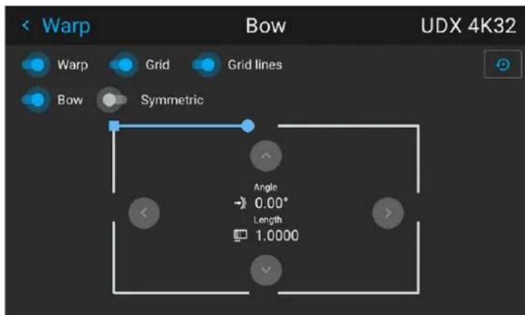
Image 6-58
- Select the desired slider and confirm.
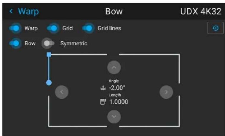
Image 6–59
- Adjust angle and linearity (length) individually to obtain the correct correction. Press enter to confirm and to switch between angle and length.

Tip: Adjust the angle by using the up and down arrow keys. Adjust the linearity by using the left and right arrow keys.
-
Repeat the previous steps for each side of the picture that must be corrected.
-
When completed, a transformation will occur in a way similar to the following example. Observe that the upper side of the picture now has an asymmetric correction.
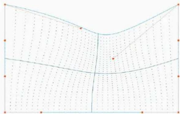
natural_image
Pure geometric diagram with grid lines and dots, no text or symbols presentImage 6–60 Example of an asymmetric bow correction

To reset the bow adjustments, select the Reset icon and confirm.
6.4.5 Warping - Warp files
Location and availability
- Menu: Installation > Warp > Warp files
- Access level: all
- Models: all
About custom warp files
Next to setting specific warp configuration in the OSD software, a custom warp grid in xml format can also uploaded or downloaded to/from the projector. This is a time-saving option when multiple projectors need a identical warp configuration.
The OSD software cannot be used to upload or download warp files. In order to upload or download war do one of the following:
- use external tools like Pulse Prospector to upload/download the warp grid in the format of an xml file. I more info, see Pulse Prospector user guide.
- use the pulse API to upload or download the warp grid in the the format of an xml file. For more info the projector API reference guide

When uploading a warp file that is too big, or with warp parameters outside the limits of the proj some irregularities can occur. It will show up in two ways:
1: No warp enabled, picture still unwarped.
2: Distortions and artifacts in the edges of the picture.
There will be no error messages or warnings in the display when this occurs. The above mentioned symptoms is the only indication of this case.
How to activate an uploaded warp grid?
- In the Warp menu, select Warp files.
Installation
Image 6–61 Warp menu, Warp files
The Warp files menu is displayed.
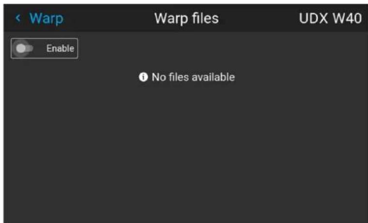
Image 6–62 Example of the warp files menu
- Enable the Enable slider.
- Select the desired warp file and confirm.
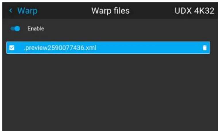
Image 6–63 Example of the Warp files menu
6.4.6 Warping - Latency control in a multi projector setup

Transport delay
The added delay in the image processing chain. The value is the number of lines relative to the output resolution.

Latency
The total time from the first pixel is coming in on an input source, until the first light representing pixel is visible on the screen. This includes the transport delay. The value is normally given in milliseconds.
Location and availability
• Location: Installation > Warp > Transport delay
- Access level: all
- Models: all
Functional description
Every projector in a multi-projector setup will have a different latency. This latency depends on the amount warp and on the frequency of the projected image. In order to have no visible difference in the overall projected image, the user needs to be able to control the latency of each projector.
The latency value can be read out in the Dashboard menu for each individual projector.
How to configure transport delay?
- Read out and note the latency of each projector in the multi-projector setup. This latency can be found under Transport delay in the Dashboard menu for each projector.
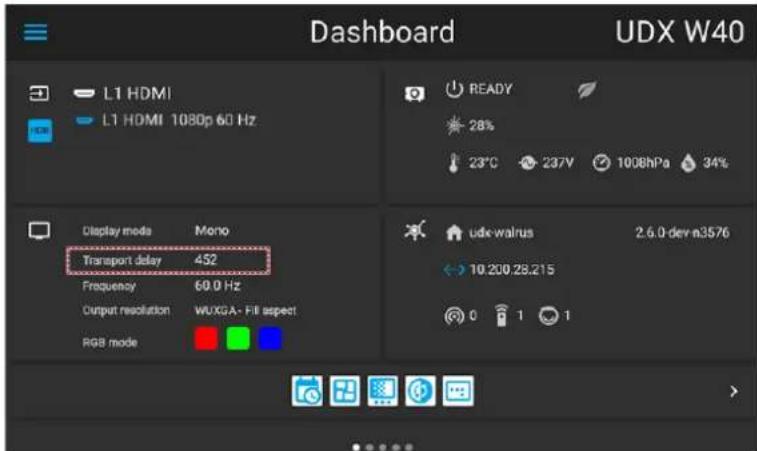
Image 6-64 Example of the Transport delay in the Dashboard menu
-
Identify the projector with the longest delay.
-
In the Warp menu, select Transport delay.
Image 6-65 Warp menu, Transport delay
The Transport delay menu is displayed.
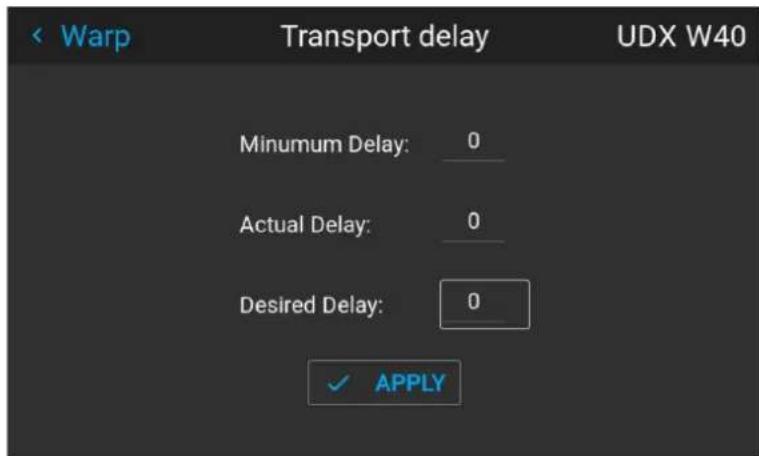
Image 6–66 Example of the Transport delay menu
- Enter the values for the delays.
- Click Apply to confirm the entered delays.
- Repeat this process for every projector in the setup.
6.5 Blending & masking
About blending
Blending is used in multi channel installation to have a seamless transition between the channels. Image blending gives the appearance of a single view, thus achieving realistic immersion for the majority of wide screen applications.
The principle is that the light intensity in the blend zone from each projector will be adjusted individually, that the rendering on the screen is perceived as from one projector.
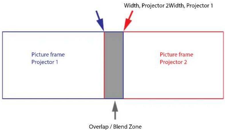
Image 6–67
From the start (mask) position, set the blend zone size per edge (left, top, right, bottom). For each edge will be a drop-off curve for the blend zone.
Waiting period and blend maintenance period
The heating and cooling down of the lens in a projector startup and shutdown cycle can have a minor effect on the blending and masking areas. Due to this, it is advised to wait 15–20 minutes after projector startup before performing blending and masking actions. This to make sure the drift on the blend region is minimal as possible. For a similar reason, it is advised to wait 15–20 minutes after projector startup before starting any blending maintenance in the existing setup.

It is recommended to perform a blend maintenance after every 10–20 startup-shutdown cycles of the projector.
Blend, mask and black level icon
On Pulse 2.5 and later, the Blend Mask Black level icon has three dots added that are either greyed out blue.
When the three dots are greyed out, no version of blending and masking or black level adjustment is enable. When the Enable sliders in one the following menus are toggled on, the icons will be lit blue:
- Blending and masking (both in Basic blend menu and in Blend mask menu)
- Black level
- Blend files
- Black level files
Image 6–68 All options in Blend Mask Black level disabled Image 6–69 Blending and masking or black level enabled
6.5.1 Basic blend
Location and availability
- Menu: Installation > Blend and mask > Basic blend
- Access level: all
- Models: all
How to set up a basic blend zone?
- In the Blend and mask menu, select Basic blend.
Image 6–70 Blend menu, Basic blend
The Basic blend menu will be displayed.
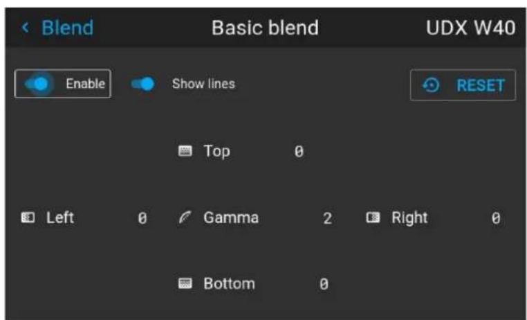
Image 6-71 Example of the basic blend menu
-
Enable the Enable slider.
-
To project masking lines on the screen, enable the Show lines slider.
-
Determine the start position of the blend area height and width to determine the dimension of the blend zone.
When the helping lines are activated, a visual indication of the screen of the installed blending area w visible.
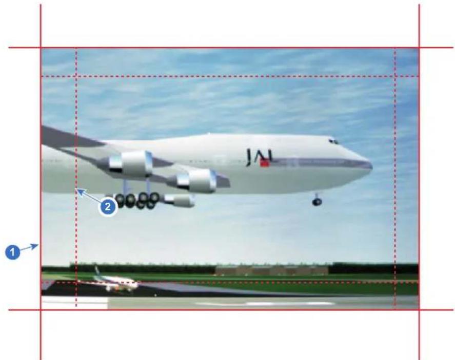
Image 6–72
1 Start position (mask)
2 Blending width
- Select one of the four starting positions values with the arrow keys and confirm.
- Use the arrow keys or remote digits to change the value of the blend zone and confirm.
- Repeat this process for all other desired sides.
- Continue by creating the blend mask. For more info, see "Blend mask", page 109.

Do not forget to disable the Show lines slider after the desired blend zone has been achieved.
6.5.2 Blend mask
Location and availability
- Menu: Installation > Blend and mask >> Blend mask
- Access level: all
- Models: all
About masking and blending width or height
Offset is used to clip the image on one or multiple sides (masking). This is used to hide parts of the pi should not be shown on the screen. For example: if the source is a Windows PC, the menu bar can be using this method.
The larger the Mask value, the more the image is masked (by black bar) at the corresponding side. E.g. mask of 100 will blank the top 100 lines.
Height or width is used to create a blending zone with a smooth brightness drop off. This is used to compensate for the double brightness in overlap areas. The value is the size of the blended area in pixel
How to set up basic blend zones?
- In the Blend mask menu, select Blend mask.
Installation
Image 6–73 Blend menu, Blend mask
The Blend mask menu is displayed.
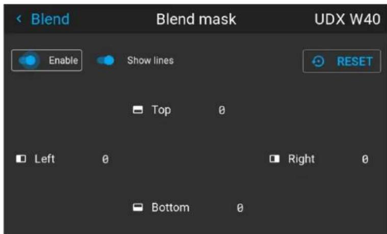
Image 6-74 Example of the blend mask menu
- Enable blending by toggling the Enable slider on.
- To project masking lines on the screen, enable the Show lines.
- Determine the start position of the mask (1) for the masking height and width, together with the desired size of the mask (2) to determine the width of the masked area.
When the helping lines are activated, a visual indication of the screen of the installed blending area w visible.
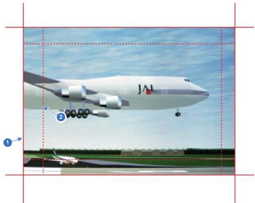
Image 6–75
1 Start position (mask)
2 Blending width
-
Select one of the four starting positions values with the arrow keys and confirm.
-
Use the arrow keys or remote digits to change the value of the mask and confirm.
-
Repeat this process for all other desired sides.

Do not forget to disable the Show lines button after the desired blend zone has been achieved.
Example of the use of blending
When projecting an image with 2 or more projectors, there is always a small overlap that should be corrected by using the blending function.

In order to obtain a satisfying result for the Blend function, the overlap / mask zone are recommended to be at least 10% of the picture width.
The basic principle is that the overlap setup in the source shall correspond with the mask width setup for projector. That means that if the overlap zone for the source is set to 500 pixels, the width of the mask the projector also must be set to 500 pixels.
First step is to align the image from the projectors as accurate as possible in a mechanical way, meaning without any optical corrections. At the same time, establish an overlap in the pictures between the two screens.
Then adjust the remaining irregularities by using the shift and warp features in the projectors to obtain the fine tuning of the alignment.
Enable blending and activate Show lines.
First set the mask width for the right edge of the first projector. Enter a width value equal to the overlap (width1).
Repeat for the left edge of the second projector.
Adjust the offset to cut the image on each side (masking).
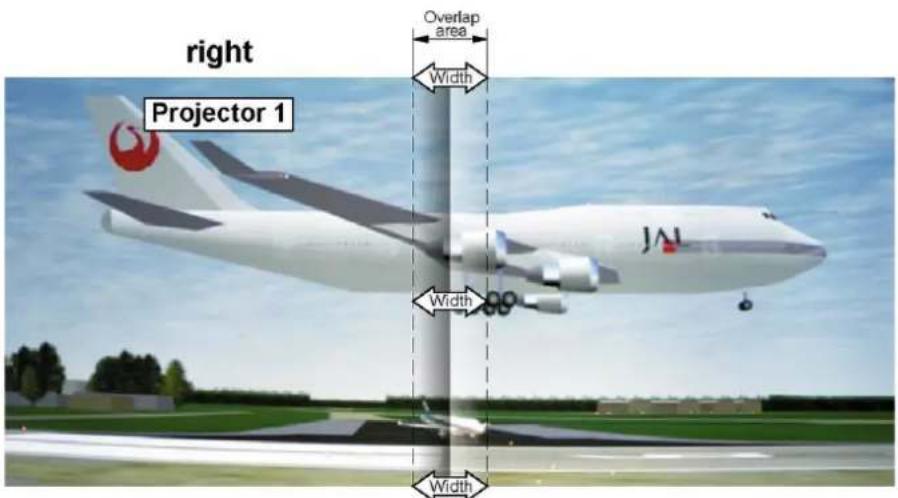
Image 6-76 Set up for projector 1
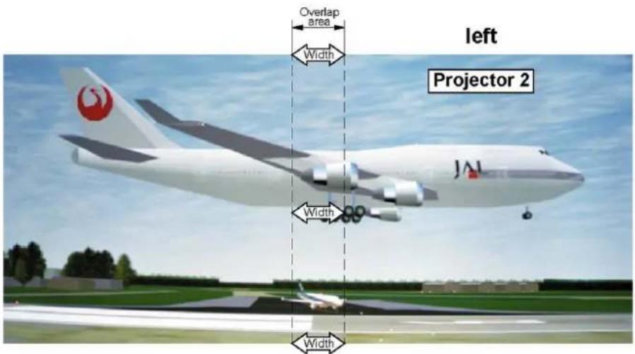
Image 6-77 Set up for projector 2
6.5.3 Blend files
Location and availability
- Menu: Installation > Blend and mask > Blend files
- Access level: all
- Models: all
About custom blend files
Next to setting the specific blending configuration in the OSD software, a custom blend configuration can be uploaded or downloaded to/from the projector. This is a timesaving option when multiple projectors need an identical blending configuration. Custom blend files should be in .png, .jpg or .tiff format.
The OSD software cannot be used to upload or download blend files. In order to upload or download ble files, do one of the following:
- use external tools like Pulse Prospector to upload/download the blend grid in the format of a png, jpg < file. For more info, see the Pulse Prospector user guide.
- use the pulse API to upload or download the blend grid in the the format of a png, jpg or tiff file. Fc info, see the projector API reference guide

When uploading custom blend files onto multiple projectors, make sure that the resolution of the blend file is supported by the projector. A mismatch of projector resolution and blend mask resolution will result in a sub-optimal image performance. Verify the supported resolutions for the specific projector model via the Introspection tool [Introspection - image - resolution - alpha]. For more info on the introspection tool, consult the Pulse API reference guide.
Blend file size limitations
Take note that the resolution of the uploaded blend file image will depend on the native resolution of the projector. The following is applicable for all Pulse powered projectors:
| Projector native resolution Example projector | Blend resolution | Bit depth | |
| WUXGA (1920x1200) I600, QDX W35, F70–W6 1920 x 1200 | 16 | ||
| WQXGA (2560x1600) | QDX 4K35, F70–4K6 | 1280 x 800 | 16 |
| Native 4K (4096x2176) | F400–N4K | 2048 x 1088 | 16 |
How to activate an uploaded blend configuration file?
- In the Blend and mask menu, select Blend files.
Image 6–78 Blend and mask menu, Blend files
The Blend files menu is displayed.
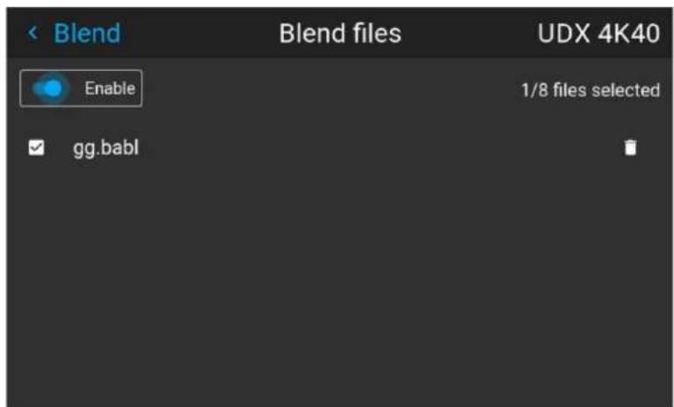
Image 6–79 Example of the blend files menu
- Enable blending by toggling the Enable slider on.
- If any custom blend files are available, select the desired file and confirm.
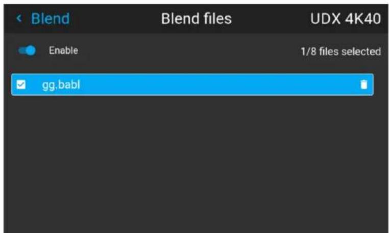
Image 6–80 Example of selecting a custom blend file
The custom blend file will be applied to the projector.
6.5.4 Black level adjustment
Location and availability
- Menu: Installation > Blend and mask > Black level
- Access level: All
- Models: all
About adjusting the black level
In a multi-projector setup, there will be a area where the image of the projectors overlap (the blend zone) black level in the blend zone will be significantly brighter than the areas outside of the blend zone. This happens because the light beams from multiple projectors are projecting on this area at the same time.
Picture Left Picture RightBlend Zone
natural_image
Two vertical dark gray bars separated by a single vertical line, no text or symbols present.Image 6-81 Example of a blend zone without black level adjustment
The purpose of the black level adjustment is to align the black levels in the blend zone to make it similar areas outside the blend zone.
The size of the black level area is calculated automatically from the blend zones. This is done by using start position and size of each edge of the blend and adding an additional size of 8 pixels to reduce the known as "sea of mirrors".
Alternatively, the offsets can be manually specified by turning off the automatic calculation. The black level value is adjusted in a 16-bit resolution from 0 to 65535.
How to adjust the black level
- In the Blend and mask menu, select Black Level.
Image 6-82 Blend and Mask menu, Black level
The Black level menu is displayed.
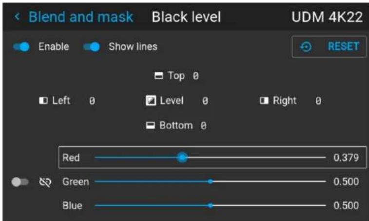
Image 6-83 Example of the default black level menu
-
Enable Black level by toggling the Enable slider on.
-
Enable the Show lines slider to have a visual aid on the screen.
-
Move the cursor to the side where the current overlapping area occurs (Top, Left, Right or Bottom) and confirm.
-
Do one of the following:
▶ Adjust the level with the arrow keys and press enter when the desired black level zone is reached.
▶ enter the black level value with the numeric keys in the remote control.
- Move the cursor to Level, press enter and adjust this level until the black level equals the level in the blend zone.
This value can also be entered by the numeric keys on the remote control.
- Repeat the procedure for any other projector projecting to this blend zone.
- Repeat the procedure for every other blend zone in the multi-projector setup.

Note: Do not forget to disable the Show lines button after the desired blend zone has been achieved.
6.5.5 RGB gain adjustment
Location and availability
- Menu: Installation > Blend and mask > Black level
- Access level: all
- Models: all
About RGB gain adjustment
The purpose of black level correction is to ensure a uniform black level in multi-projector setups. Even with two projectors are of the same type, different projectors will output slightly different colors for black due to minor variations in their optical components. So if the projected image of the projectors overlap, there will different black levels: one for the zone where only the picture of the left projector (zone 1), one for the zone (zone 2), and one for the zone where there is only the picture of the right projector (zone 3).
Picture Left Picture RightBlend Zone
natural_image
Pure black rectangle with a vertical gray stripe on the left edge (no text or symbols)Image 6–84
The black levels for zone 1 and zone 3 are typically corrected by defining a black level mask, which is to the image of each projector. This system is already in place but the applied mask is monochrome.
Using the RGB adjustment of the Basic Black Level menu, the multiplication factors (gains) for the Red, C and Blue colors can be adjusted separately.
How to perform an RGB adjustment
- In the Blend and mask menu, select Black Level.
Image 6–85 Blend and Mask menu, Black level
The Black level menu is displayed.
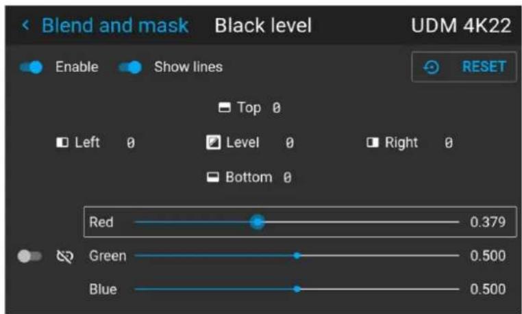
Image 6-86 Example of the default black level menu
-
Enable Black level by toggling the Enable slider on.
-
Enable the Show lines slider to have a visual aid on the screen.
-
Select one of the three sliders on the bottom of the menu (Red, Green or Blue).
-
Use the left and right arrow keys to modify the gain of the chosen color and confirm.
-
Repeat for every slider until the desired result is achieved on screen.
-
Repeat the procedure for any other projector projecting to this blend zone.
-
Repeat the procedure for every other blend zone in the multi-projector setup.

Note: Do not forget to disable the Show lines button after the desired blend zone has been achieved.
6.5.6 Black level files
Location and availability
- Menu: Installation > Blend and mask > Black level files
- Access level: all
- Models: all
About custom black level files
Next to setting the specific black level adjustment, a custom black level adjustment file can be uploaded c downloaded to/from the projector. This custom file should be in png, jpeg or tiff format.
To upload or download black Level adjustment files, use Pulse Prospector or upload/download the black level adjustment file in the format of an XML file. Alternatively, can contact the "file endpoint" directly via the CPU program or some other tool that supports HTTPS upload.
For more information on uploading/downloading black level files using Pulse Prospector, refer to the Pulse Prospector user manual. For more information on uploading/downloading black level files using curl or other tools that supports HTTPS upload, refer to the Pulse API Reference Guide.

When uploading custom black level files onto multiple projectors, make sure that the resolution of the file is supported by the projector. A mismatch of projector resolution and black level file resolution will result in a sub-optimal image performance. Verify the supported resolutions for the specific projector model via the Introspection tool [Introspection - image - resolution - alpha]. For more info on the introspection tool, consult the Pulse API reference guide.
Black level file size limitations
Take note that the resolution of the uploaded black level file image will depend on the native resolution of projector. The following is applicable for all Pulse powered projectors:
| Projector native resolution Example projector | Blend resolution | Bit depth | |
| WUXGA (1920x1200) I600, QDX W35, F70–W6 1920 x 1200 16 | |||
| WQXGA (2560x1600) QDX 4K35, F70–4K6 1280 x 800 16 | |||
| Native 4K (4096x2176) F400–N4K 2048 x 1088 16 | |||
How to activate an uploaded Black Level adjustment file?
- In the Blend and mask menu, select Black level files.
Image 6–87 Blend and mask menu, Black level files
The Black level files menu is displayed.
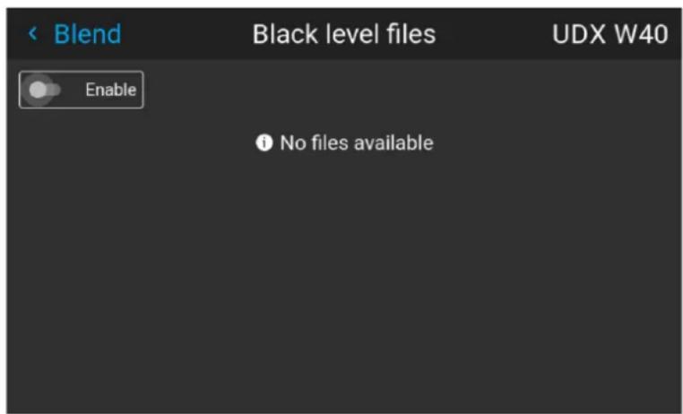
Image 6–88 Example of the black level files menu
- If any custom black level adjustment files are available, select the desired file.
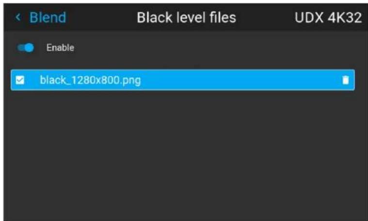
Image 6–89 Example of custom black level files selected
- Make sure the Enable slider is toggled on to activate the selected black level file.
6.6 Illumination
Location and availability
- Menu: Installation > Illumination
- Access level: all
- Models: all
- Requirements: Light source must be on, shutter must be open
What can be done?
Within a certain limit, the light output of the light source can be reduced by reducing the power slider.
Alternatively, CLO mode (Constant light output) can be enabled for a constant light output over a longer p of time.
About CLO mode
All light sources naturally decrease their intensity over time. In order to prevent a decreasing output in a projector setup, CLO mode can be enabled to ensure a Constant Light Output (CLO).
CLO mode will ensure that the projector regulates its illumination power to maintain the same level of output light during the lifetime of the light source. This however requires that the light source power is not set to from the start, but to a lower value. The lower this value is set, the longer the projector will be able to the output level.

CLO mode can not be used when the light source is off, the shutter is closed or if the dynamic feature is enabled and active (if applicable).
How to adapt the power
- In the Installation menu, select Illumination.
Image 6–90 Installation menu, illumination
The Illumination menu will be displayed.
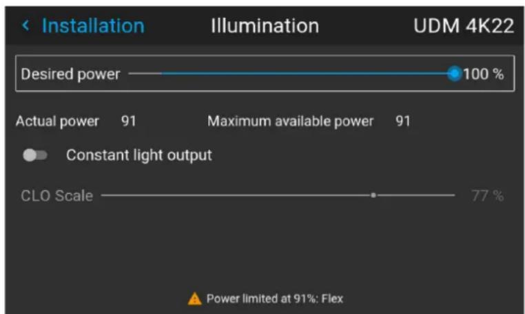
bar
| Category | Value | | -------------------- | ----- | | Desired power | 100% | | Actual power | 91% | | Maximum available power | 91% | | Constant light output | - | | CLO Scale | 77% |Image 6–91 Example of the Illumination menu
- Use the Slider to change the power value.
-
If CLO mode is desired, enable the Constant light output slider.
-
If CLO mode is enabled, use the CLO Scale slider to the desired value.

Note: The CLO scale can not be higher than the maximum available power of the light source.
6.7 IR illumination – Night vision functionality
Location and availability
- Menu: Installation >> IR illumination
- Access level: all
• Models: FS40, FS70, FS400
About
In combination with Night Vision Goggles (NVG), Night vision mode will give a realistic rendering of the environment during night time. This will visualize in a realistic way, night time, dusk and dawn, and limited visibility scenarios.
Night Vision projectors have two light sources. A standard light source available on all projector models of same family, and an IR LED light source, exclusive to “FS” models the projector family.
- The standard light source of the projector is used to visualize visible light (VL).
- The IR LED light source is used to visualize the infrared spectrum (IR).
The IR light source has a wavelength of 740 nm
Displaying infrared
In night vision mode with 2 separate inputs, the projector displays the two inputs alternating every other from. The output is displayed a double speed of the inputs, i.e. at 120Hz in case of 60Hz input. The DMD is illuminated with visible RGB light every other frame, while the IR "light" is illuminating the DMD all the time
For more info on specific color component mapping, see "Nightvision color component mapping", page 251.
How to achieve Night Vision mode
The power output of each light source can be individually controlled. To set up a proper night vision mod things must be done:
- Reduce the Desired power slider of the regular light source to the lowest possible setting to reduce the light intensity (daylight).
- Set the IRLED desired power slider of the IR LED light source to the desired maximum light output.
By doing this, the IR LED light source will become the dominant light source and the image on screen with visible with night vision goggles.
To set up the IR illumination, navigator to the appropriate Illumination menus. There are two Illumination menus, each with a power slider; one for the LED Desired power (daylight), and one for the IR LED Des power (Night Vision).
While wearing the night vision goggles, the IR LED slider can be adjusted, as well as the contribution level each individual LED color (red / green / blue).
Alternatively, the power level of both light sources can be mixed. By mixing both light sources it is possible to simulate other visibility scenarios for other times of the day, such as “twilight mode”.

When enabling IR mode (Night Vision), the Vizsim Bright will be set as default. If another approach to IR (Night Vision), is performed, e.g. by selecting Auto Stereo Mode and at the same time turn the LED's, Vizsim Bright must be set manually."BrilliantColpage 67 If not then set to Vizsim Bright, the picture will be distorted.
Disable this function in IR mode
The Vizsim Bright mode will not cause this distortion.
Lightsource and DMD lifetime versus ambient temperature.
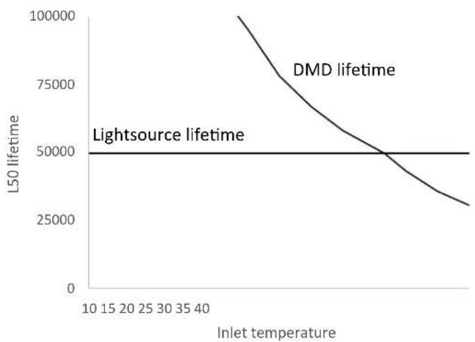
line
| Inlet temperature | L50 lifetime | | ----------------- | ------------ | | 10 | 100000 | | 15 | 75000 | | 20 | 60000 | | 25 | 50000 | | 30 | 45000 | | 35 | 40000 | | 40 | 35000 |Image 6–92
How to enable Night Vision
- In the Installation menu, select IR illumination.
Image 6-93 Installation menu, IR Illumination
The IR illumination menu will be displayed.
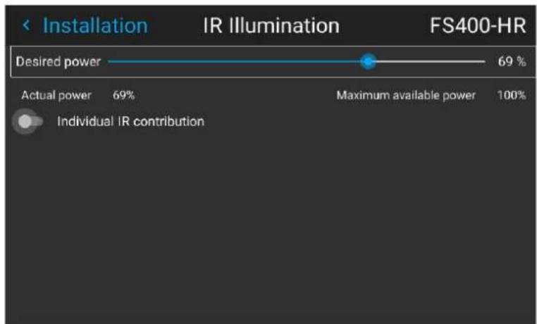
bar
| Category | Value | | --------------------- | ----- | | Desired power | 69% | | Actual power | 69% | | Maximum available power | 100% | | Individual IR contribution | (value not labeled) |Image 6–94 Example of the IR Illumination menu
-
Use the Desired power slider to change the power value.
-
Enable the Individual IR contribution slider, if the contribution of individual colors of the IR LEDs needs to be decreased.

Note: Individual IR contribution does not work while CLO is enabled. For this reason, if CLO is enabled, the enable slider will automatically become disabled.
The individual LED sliders will become visible and enabled.
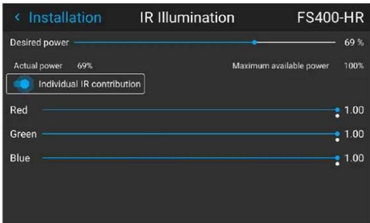
bar
| Color | Power Level | |-------|-------------| | Red | 1.00 | | Green | 1.00 | | Blue | 1.00 |Image 6–95 Example of the IR illumination menu with the Red, Green and Blue sliders visible
- Set the contribution level of each color by dragging the sliders to the desired output level.
• Available range: 0.00 to 1.00
- Default value: 1.00
- Step: 0.01
6.8 3D projection
3D setup
The projector is capable of displaying 3D images and movies in active stereoscopic 3D.
Setup of a 3D installation requires an advanced understanding of 3D systems, both for the projector as w for the system the signal source originates from. In a 3D setup it is crucial that the projected images are perfectly synchronized through the whole signal path, from the signal source to the picture viewed through 3D goggles.
Regarding setting up the proper signal source, please refer to the user manual or online help for that gra card. For example: when using NVIDIA Quadro cards, use the NVIDIA Control Panel to manage the 3D settings of the graphics card.
6.8.1 About Active Stereo & Passive Stereo

Passive Stereo
Passive Stereoscopic 3D (also known as "Passive Stereo") is the standard method of creating the illusion of depth in an image, by means of stereopsis for binocular vision.
To present stereoscopic pictures, two images are projected superimposed onto the same screen through polarizing filters or presented on a display with polarized filters. For Digital Cinema, a silver screen is used so that polarization is preserved. On most passive displays every other row of pixels are polarized for one eye or the other. This method is also known as interlacing.
The viewer wears glasses which contain a pair of opposite polarizing filters. As each filter only passes light which is similarly polarized and blocks the opposite polarized light, each eye only sees one of the images, and the effect is achieved.

Active Stereo
Field sequential 3D (also known as active 3D or "Active Stereo") is a technique of displaying stereoscopic 3D images. It works by only presenting the image intended for the left eye while blocking the right eye's view, then presenting the right-eye image while blocking the left eye, and repeating this so rapidly that the interruptions do not interfere with the perceived fusion of the two images into a single 3D image.
This system setup uses liquid crystal shutter glasses (also known as active shutter glasses). Each eye's glass contains a liquid crystal layer which has the property of becoming opaque when voltage is applied, being otherwise transparent. The glasses are controlled by a timing signal that allows the glasses to alternately block one eye, and then the other, in synchronization with the refresh rate of the screen. The timing synchronization to the video equipment may be achieved via a wired signal or via wireless communication, this by using either an infrared or radio frequency (e.g. Bluetooth, DLP link) transmitter.
Projection method used
This projector can only show active 3D images, used in combination with a 3D emitter and active shutter glasses. While it is allowed to connect passive stereo source signals, the image processing of the projector will convert those signals to an active 3D compatible image.
The 3D settings menu allows to fine-tune the 3D settings accordingly to the specifications of the 3D emitter

If a 3D emitter is used that radiates IR beams, the IR beams may interfere with the IR communication between projector and the RCU. If such interference occurs, connect the RCU to the projector using the remote cable. It is advised to turn the IR receivers on the projector off to avoid the 3D emitter interference. To turn off the IR receivers on the projector, see "Remote control – IR sensors", page 148.
6.8.2 Image Generators and IG pixel shift

Image Generator (IG)
An image generator (IG) creates visual scenes of a simulated environment from the perspective of participant. The visual scenes can be displayed on multiple simulation projectors in a dome setup. The scenes can be rendered in the visible spectrum for an "out-the-window" experience, or in other wavelengths to simulate optical sensors. An image generator generates scenes very quickly to maintain a realistic sense of motion for the participant.

IG PixelShift
Image Generator Pixel Shift, hereafter referred to as IG pixel shift, is a method for achieving 4K resolution using the 4K actuator, where the phase offset between 2 subframes is generated by the source (the Image Generator, or IG). When the IG renders the subframes, the exact position of the rendered objects in the 3D model is known and the correct viewpoint for all objects is exact. This instead of the projector applying static filtering on the resulting 4K images to guess the subframes.
About IG pixel shift
On simulation projectors, the IG source can be connected on two identical connectors (e.g. DisplayPort 1 and 2, or DVI-D 1 and 2 (if available)). Using the Pixel shift module, a 4K rendering of the image will be dis
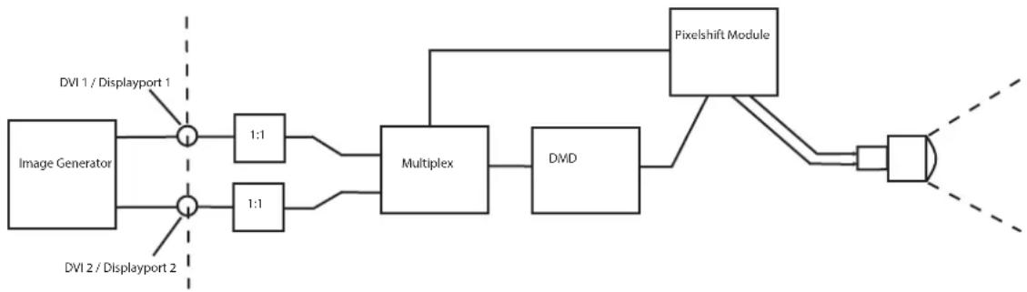
flowchart
graph LR
    A["Image Generator"] --> B["1:1"]
    C["DVI 1 / Displayport 1"] --> B
    D["DVI 2 / Displayport 2"] --> E["1:1"]
    B --> F["Multiplex"]
    E --> F
    F --> G["DMD"]
    G --> H["Pixelshift Module"]
    H --> I["Output"]
Image 6–96 IG Pixelshift. Principle of operation.
IG pixel shift in Night Vision mode
When having a “Stealth” variant projector, two image generators can be used to use pixel shift. One IG v generate the “daylight” or “out-the-window” image, whereas the other IG will generate the Infra-Red image.
The process of Night Vision pixel shift is identical, but the actuator will continue the pixel shift when the switches from daylight to night vision.
6.8.3 Setup process 3D projection
How to setup 3D projection?
- Connect the proper source cables to the projector. For more info, see "Connection possibilities", page 125.
- Set up and connect the 3D emitter to the projector. For more info, refer to the user manual of the 3D emitter.
- Power on the projector completely.
- Select the correct stitched source Input in the Source menu. See "Source", page 29.
- Depending on the chosen 3D emitter and chosen source, correct the 3D setup. For more info, see "3D Setup", page 126.
6.8.4 Connection possibilities
Connecting with the projector connection panel
• Models: FI40, FS40, F70, Bragi, Balder
- Connector: DisplayPort 1.2 or DVI
Use one of the following methods. The resulting image will always be an Active Stereo image.
| Source | Layout mode | Video cable | Timing / | Fixed configuration? | Color depth |
| Active Stereo (sequential L/R) | Standard layout | (1x2560Hz) | x 1600 @120 | 30 bpp | |
| Passive Stereo (separate L/R) | Standard layout | (1x3840 layout) | x 2160 @60 | •Hcable 1: left eye 30 bpp• Cable 2: right eye | |
| Passive Stereo pipe L/R) | (dual Column mode layout) | (2x920) | x 2160 @60 | •Hcable 1: left eye 30 bpp• Cable 2: right eye |
Connecting with the quad combo input panel
There is only one way of projecting Active stereoscopic 3D with the Combo input card, using the following setup:
- Models: QDX, UDM, UDX, I600, F400, Njord, Hodr.
- Connector: DisplayPort 1.2 or HDMI
• Source: Active Stereo (sequential L/R) - Layout mode: Standard layout (1x1 layout)
• Video Timing: 2560 x 1600 (WQXGA) @120 Hz
• Color depth: 30 bpp
Connecting with the quad DP 1.2 Input pane
- Models: QDX, UDM, UDX, I600, F400, Njord, Hodr
- Connector: DisplayPort 1.2
Use one of the following methods. The resulting image will always be an Active Stereo image.
| Source | Layout mode | Video Timing / cable | Fixed configuration? | Color depth |
| Active Stereo (sequential L/R) | Standard layout (1x1 layout) | 2560 x 1600 @120 Hz | 30 bpp | |
| Active Stereo (sequential L/R) | 4 Column mode (4x1 layout) | 960 x 2160 @120 Hz | 30 bpp | |
| Active Stereo (sequential L/R) | 4 Quadrant mode (2x2 layout) | 1920 x 1080 @120 Hz | 30 bpp | |
| Passive Stereo (separate L/R) | Standard layout (1x1 layout) | 3840 x 2160 @60 Hz | Cable 1: left eyeCable 2: right eye | 30 bpp |
| Passive Stereo (dual pipe L/R) | 2 Column mode (2x1 layout) | 1920 x 2160 @60 Hz | Cable 1: left eye, left columnCable 2: left eye, right columnCable 3: right eye, left columnCable 4: right eye, right column | 30 bpp |
6.8.5 3D Setup
Location and availability
- Menu location: Installation >> 3D Setup
- Access level: all
- Models: all
Why change the 3D setup?
While Barco can provide a 3D emitter and active shutter glasses as options to this projector, other 3D em and active shutter glasses can be used. Since glasses and emitters can have various specifications compared to the ones Barco provides, the 3D setup menu allows the user to configure the output image to the specifications of the glasses and emitter. The following can be configured:
- Swap eyes: Inverts the stereo Sync output signal (depending on the chosen 3D emitter and glasses).
- Swap frame pair: Corrects the frame doubling sequence. If the frame rate of the projected moving 3D content doesn't look smooth, this option may help improve this.
- Dark time: Select how much dark time the projected image will have between frames.
- Display mode: Choose the desired output mode. For more details, see further.
- Sync delay: Increase or decrease the sync delay. The scale goes from -10 000 to +10 000 with a step of 100 .
Choosing the desired output mode
The following output modes are available:
• Auto Stereo: Automatic mode (2D input = 2D output, 3D input = Active Stereo output).
- Mono: Forces all source signals to 2D output.
• Active Stereo: Forces all source signals to Active Stereoscopic 3D.
Use the following table as an indicator of what display mode is required.
Source signal
Auto Stereo Mono Active Stereo
| 2D Source Output is a 2D image Output is a 2D image Output is in Active Stereo |
| Active Stereo source Output is in Active Stereo Output is a 2D image Output is in Active Stereo |
| Passive Stereo source Output is in Active Stereo Output is a 2D image Output is in Active Stereo |

When a different display mode is chosen compared to the source signal (e.g. Active Stereo source with Mono output), advanced image processing will make sure a desirable image is displayed.
Extra output modes for simulation and stealth projectors
On simulation projectors, the following extra output mode is available:
- IGPixelshift: Forces the source signals to an image ideal for simulation environments
On Stealth Simulation projectors, the following extra output modes are available:
• NightVision: Forces the source signal to Nightvision mode, using the IR LED light source - IGPixelshift: Forces the source signals to an image ideal for simulation environments
- IGPixelShiftNV: Forces the source signals to an image for simulation environments, while using the IR LED light source
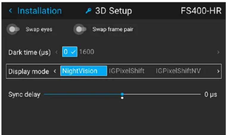
Image 6–97 Example of the extra options on a Stealth Simulation projector
How to adjust the projector to the 3D emitter?
- In the Installation menu, select 3D Setup.
Image 6-98 Installation menu, 3D setup
The 3D setup menu is displayed.
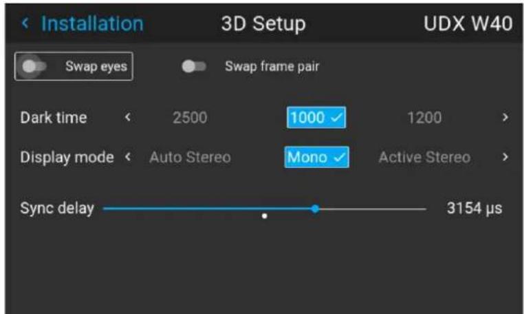
Image 6-99 Example of the 3D setup menu on a UDX
- If it is necessary to invert the stereo sync output, enable the Swap eyes option.
- If the projected moving 3D content doesn't look smooth enough, enable the Swap frame pair option to help improve this.
- Select the desired the stereo Dark Time.
- Select the desired Display mode.
- Use the slider to set the desired stereo Sync delay.
Projector profiles
7
7.1 Profiles introduction.... 130
7.2 Saving the current projector settings in a profile 132
7.3 Assigning a projector profile to a preset 134
7.4 Deleting a projector profile....136
7.1 Profiles introduction
About Profiles
The profile function makes it possible to store different profiles / projector setups for different use cases, a quickly recall them when needed. This means that it is not necessary to enter a lot of different menus to the projector setup for specific recurring use cases.
A few examples of different user cases are:
- Building temporary gaming setups in bright auditorium-level environment, versus a darker “gaming room” or “cave”.
- Playing content from an old DVD versus playing the latest release from an HDR-coded Blu-Ray.
- A rental projector that can be rented out for business presentations, concerts and other events that have different but recurring forms of content.
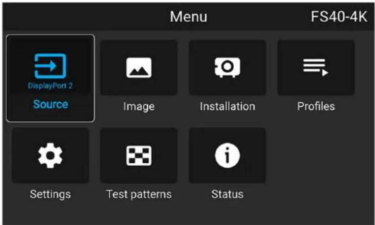
Image 7-1
Available profile settings
The following projector settings can be saved to a projector profile:
| Profile domain name | Settings saved |
| Illumination | ·Illumination power of light source·Light sensor enabled / disabled·Light sensor set point |
| Source Active source selection & EDID | |
| Image | ·Contrast·Brightness·Saturation·Sharpness·Gamma·Used gamma type·Digital zoom (width / height / factor + enabled/disabled)·Digital shift (x / y + enabled / disabled)·Output resolution |
| Display (3D settings) | ·3D Display mode used·Swap eyes on / off·Swap frame pair on / off·Dark time and sync delay values |
| RealcolorTM | ·Brilliant Color mode (if available)·P7 desired values·P7 measured values |
| Warp | ·Warp status enabled / disabledScreen sizeWarp file selected (if available)Transport delayNote: Bow and 4 corners warp cannot be saved. |
| Blend | Blend mask enabled / disabledAll Masks (top / bottom / left / right) and heights (top / bottom / left / right)Blend files enabled / disabled (if available)Blend file selected (if available) |
| Black level | Black level file enabled / disabledBlack Level file selected (if available)Basic black level enabled / disabledBlack level settings (top / bottom / left / right)RGB gain values (Red, Green and Blue values) |
| HDR | Screen luminance (unit and value)HDR Boost valueDynaBlack mode |
| Installation | Lens parameters (lens zoom, focus, shift and iris (if available))Orientation (mounting & projection)Scaling modePosition of motorized frame (if used).Shutter status (open or closed). |
| Cooling8 | Selected Cooling mode |
| Operational mode8 | Selected Operational mode |
7.2 Saving the current projector settings in a profile

Make sure the projector is fully configured as desired before saving the settings.
Location and availability
- Menu: Profiles > Edit
- Access level: all
- Models: all
How to save the current projector settings?
- In the Profiles menu, select Edit.
Image 7-2 Profiles menu, edit
The Profile edit menu is displayed.
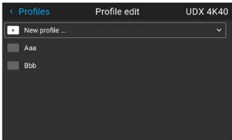
Image 7-3 Profile edit menu
- Select New Profile... and confirm.
The New Profile pane is expanded and fully displayed.
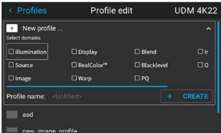
Image 7-4 Example of the new profile pane
- Select and confirm each of the settings to be saved in this profile.
- Select the field next to Profile Name and confirm.
The on-screen keyboard will be prompted
- Use the on-screen keyboard to enter a valid profile name.
- Select CREATE and confirm to save the current profile settings.
7.3 Assigning a projector profile to a preset

This procedure assumes at least one projector profile has been created.
Location and availability
- Menu: Profiles > Edit
- Access level: all
- Models: all
How to assign a projector profile to a preset
- In the Profiles menu, select Edit.
Image 7-5 Profiles menu, edit
The Profile edit menu is displayed.
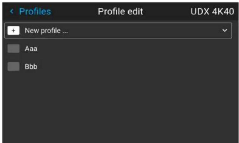
Image 7-6 Profile edit menu
- Select the desired projector profile from the list and confirm.
The profile pane for the selected profile will expand.
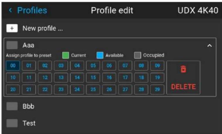
Image 7-7 Example of a projector profile with available preset slots
- Select a preset slot and confirm.
The selected preset slot is now shown next to the profile name.
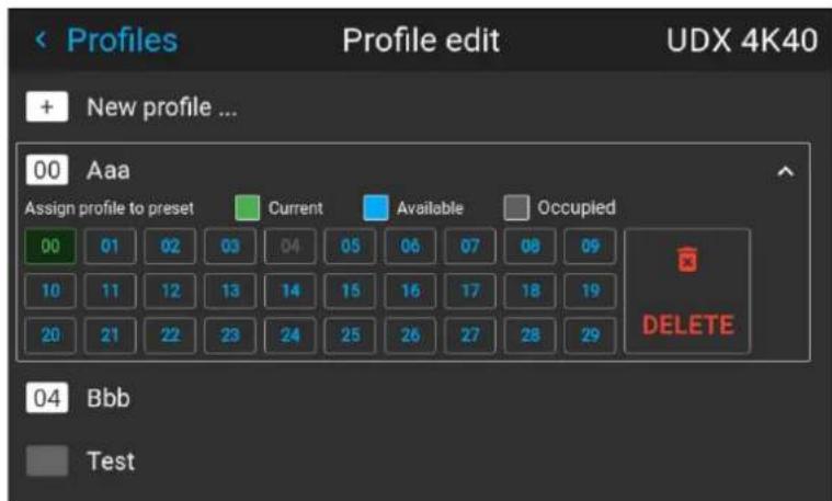
Image 7-8 Example of projector profiles allocated to preset slots (here slot 00 and 04)
7.4 Deleting a projector profile
Location and availability
- Menu: Profiles > Edit
- Access level: all
- Models: all
How to delete a profile
- In the Profiles menu, select Edit.
Image 7-9 Profiles menu, edit
The Profile edit menu is displayed.
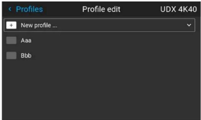
Image 7-10 Profile edit menu
- Select the undesired projector profile and confirm to expand it.
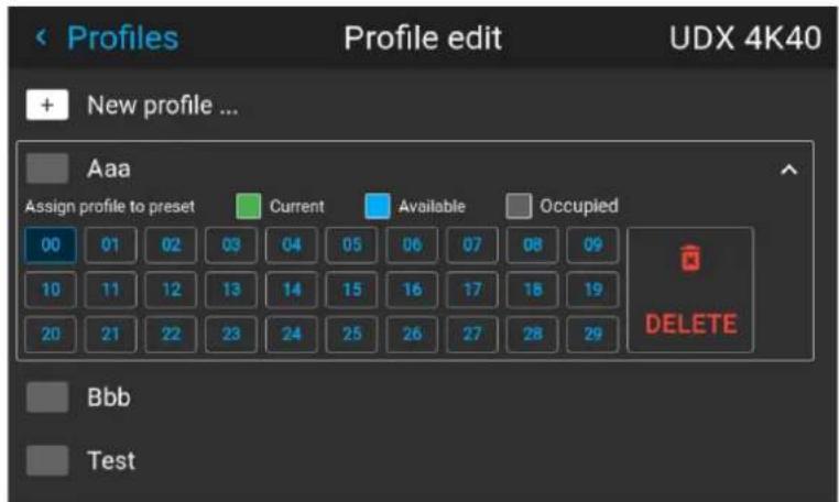
Image 7-11 Example of a projector profile with available preset slots
- Use the arrow keys to select Delete and confirm.
A confirm dialog will be prompted.
- Confirm the delete action.
The profile will be deleted.
Settings
8
8.1 Product registration.... 140
8.2 Communication 147
8.3 User interface....167
8.4 Date and time....171
8.5 Scheduler 175
8.6 Power settings....180
8.7 System 185
8.8 Lens features 189
8.9 Maintenance....190
8.10 Advanced settings 203
8.11 General 219
8.1 Product registration
8.1.1 About product registration
Overview
The driver for online product registration is to create a better customer relation and organize a better customer service. Product registration provides a much better insight into what products a certain customer has (mod built year, serial numbers, etc...). This takes away the administration hurdles when the customer calls for support of one of his products and it avoids unnecessary mistakes like providing incorrect spare parts due model numbers being unclear etc....
Barco has its own IoT platform called Insights Management Suite. This platform enables a more efficient projector fleet management through remote monitoring of the projector parameters.
IoT functionality
A quick preview of the IoT functionality:
Optimized fleet management - The IoT platform allows you to get rid of time-consuming and error-prone manual administration thanks to the automatic cloud-based storage of projectors' usage data and light-source run-times. The platform allows you to manage and control your entire fleet in a more efficient way. Keep of the past, to make the best decisions in the future.
Efficient Diagnosis - The IoT platform allows remote device diagnosis. The live dashboards gives real-time information on the operating and environmental conditions of the projectors. Diagnose and solve issues before they turn into failures thanks to the e-mail warning notifications and help your customers more effectively with prompt remote assistance.
Plug and play - You are able to access the IoT platform on any device with internet access, whether it's your laptop, mobile phone or tablet. The integrated cellular module minimizes the set-up-time as there's no need cables, extra networks or gateways. And the IoT platform data can also easily be combined with your own tools and processes.
Models
All this functionality requires a customer product registration. The product registration step makes the link between the product and its cloud data stored in a customers' cloud account and provides a customer access to the cloud data of its product fleet.
The registration to the Insights Management Suite is available for several projector models.
G-series:
- G50
- G62
- G100
• 1600
• QDX
- UDX
• UDM ^10
• XDM
• XDX
- Njord
- Hodr
- Freya
This list can change over time. Check the latest version on Barco's website.
8.1.2 Product registration workflow
Workflow
The product registration concept and security is built around a unique product identification file which is installed on each projector during the production of the device. This identification file is linked with a product license file which will be sent to the customer when the product registration is finalized.
The product registration process goes as follows:
- Get the unique product identification file from the projector using one of the methods listed in this topic
- Upload the product identification file in Barco's product registration portal
- Link the product identification file file to the user's mybarco account. In return, a license file will be sent back.
- Install the license file on the projector.
Methods
There are several methods to obtain the product identification file from the projector and upload the obtain license file. However, not all methods are available on all projector models
The following methods are available:
1. Pulse OSD:
- Uses the projector OSD and a USB flash drive.
• Supported for: QDX, UDX, UDM, I600, Njord and Hodr.
2. Pulse Prospector:
- Uses a computer or tablet with network access to the projector.
• Supported on Pulse 2.5 and later
• Supported for QDX, UDX, UDM, I600, Njord and Hodr.
3. Pulse Mobile App:
- Uses a mobile device with the Pulse Mobile app installed.
• Supported on Pulse 2.6 and later
• Supported on QDX, UDX, UDM, I600, Njord and Hodr.
4. Projector Toolset for Pulse:
- Uses a computer with the Projector Toolset for Pulse installed on it.
- Supported on Projector Toolset for Pulse version 1.20 and later.
• Supported for G50, G62, G100, UDX, UDM, Njord, Hodr. - Note: No longer supported from Pulse 2.6 and later.
5. Web Communicator:
- Uses a laptop, with access to the projector.
• Supported on Web Communicator 1.5 and later
• Supported for: XDM, XDX and Freya
About the mandatory registration for UDM, Njord and Hodr
Each UDM projector (once enabled for IoT, either out of the factory or once upgraded to a Pulse release supports IoT) will have a 100 hours illumination grace period for registration. During this period the projector will function as normal. If a user continues to ignore the registration requests at the end of the 100 hours projector will show a label Unregistered
Image 8-1 Example of the text on the projected image
8.1.3 Product registration for Pulse OSD using the Barco Pulse Mobile app
Location and availability
- Menu: Settings > Product registration
- Access level: Power user
- Model: all
• Availability: Pulse 2.6 and later
Required tools
Barco Pulse Mobile app
How to register using the QR code
- Download and install the Barco Pulse Mobile app.

Tip: The Barco Pulse Mobile app is available in both in the Google Play Store, as in the Apple App Store.
- Open the Barco Pulse Mobile app.
- Add the current projector to your projector list.
- Scan the QR code visible on the OSD and LCD screen with the Barco Pulse Mobile app.
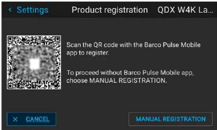
Image 8-2 Example of a QR code to be scanned with the Barco app
- Follow the instructions from the registration wizard on the Barco Pulse Mobile app to register the projector.
8.1.4 Manual product registration
Location and availability
- Menu: Settings > Product registration
- Access level: Power user
- Model: all

Manual product registration is not yet supported on QDX. This will be supported in a future releas
Required tools
USB flash drive
How to register manually
- Click Manual Registration.
The manual registration procedure starts.
- Insert a USB flash drive in the USB port of the projector. The storage device must be formatted as FAT32.
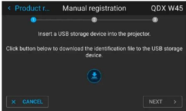
Image 8-3 Example of the first page of product registration
- Click on the download icon.
The identification file will be downloaded. If successful, the Next button will become enabled.
- Click Next.
The second page will be displayed.
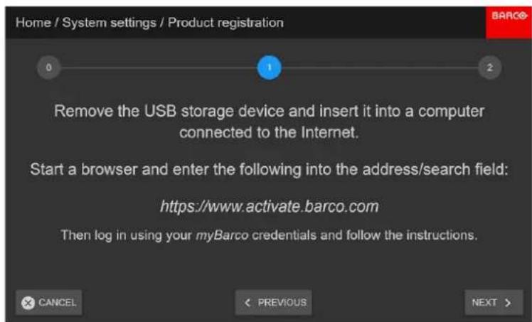
Image 8-4 An example of the second page
-
Remove the USB flash drive.
-
Activate the product online as follows:
a) Insert the USB flash drive onto a computer or tablet that can connect with the internet.
b) Open a web browser and surf Barco's product registration portal, https://www.activate.barco.com.
Settings
c) Log in with your myBarco credentials.
If you do not have an account, go to the Barco website and create a myBarco account. The Activate your Barco product window is displayed.
Activate your Barco product

You are only a few steps away from activating your Barco product/system.
Select the identification file you downloaded and upload it into the box below. You can either drag and drop or browse the file from your computer.

Image 8-5
d) Browse to the identification file from the USB storage device.
e) Drag and drop the file onto the drop area in the web browser.
Alternatively, you can use the Browse link to activate a file picker window and select the file.
Activate your Barco product
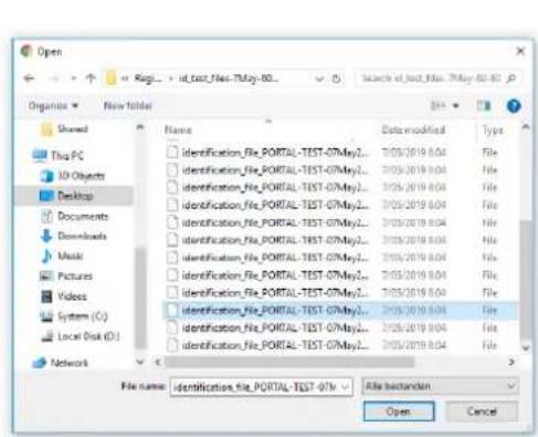

you are only a few steps away from activating your own product/system
Select the identification file you downloaded and upload it into the box below. You can either drag and drop or browse the file from your computer.
Image 8-6
f) Complete the necessary projector and/or account details.
Activate your Barco product

Please complete the registration fees below. This auto will help our customers' services to help you and your customer fees and more effectively.
After registration, both you and your own site contact person will get an email confirming the registration and activation of the Banca product.
If your security measure you cannot enter Item data please fill in your professional contact details;
Projector name
U201406-123458789
Location
Select a choice or create a new location
Select a Socialist
Create a new location
Registered by
AV Rental
Pieter Gillegott-Mergahmann
pieter.gllegor-vergauwen@banco.com
George Stephensonstraat 17
8013 M. Zhenke
Netherlands

Go to step 3
Image 8-7
g) Click Go to step 3.
h) Read and agree to the user agreement. Click Confirm if you read the terms and agree with it.
Activate your Barco product

Please check if the data follows is correct. Click Back to customer details if you want to change anything.
is all data correct? Accept the UCLA below and Click Confirm. A confirmation email with this information will be sent to you and the end-user.
Registration file
identification_file_PORTAL-TEST-07May2019-UDK-70
Projector name
UOX 406-125856789
End-user customer details
Santo Liège
Amaud Bremes
www.cib.com.cn
Roe de Mulhouse 30
-0328: Li6gy
(No text)
End-User License Agreement
Projector Toolset
Product Specific End User License Agreement
THIS PRODUCT SPECIFIC USER LICENSE AGREEMENT (EULA) TOGETHER WITH THE BARCO GENERAL EULA ATTACHED HERETO SET OUT THE TERMS OF USE OF THE SOFTWARE.
PLEASE READ THIS DOCUMENT CAREFULLY BEFORE OPENING OR DOWNLOADING AND USING THE SOFTWARE.
DO NOT ACCEPT THE LICENSE AND DO NOT INSTALL DOWNLOAD ACCESS OR OTHERWISE COPY OR USE ALL OR ANY PORTION OF THE SOFTWARE UNLESS YOU
I have read the terms and conditions of the End-User License Agreement and hereby accept them. Tavari and Candelang
Back to Customer Details

Image 8-8
i) Click Download and store the resulting license on the flash drive.
Thank you for activating your Barco product
Image 8-9
-
Insert the USB flash drive in the projector again.
-
Click Next on the download screen on the projector to open the upload screen.
The Upload page will be displayed.
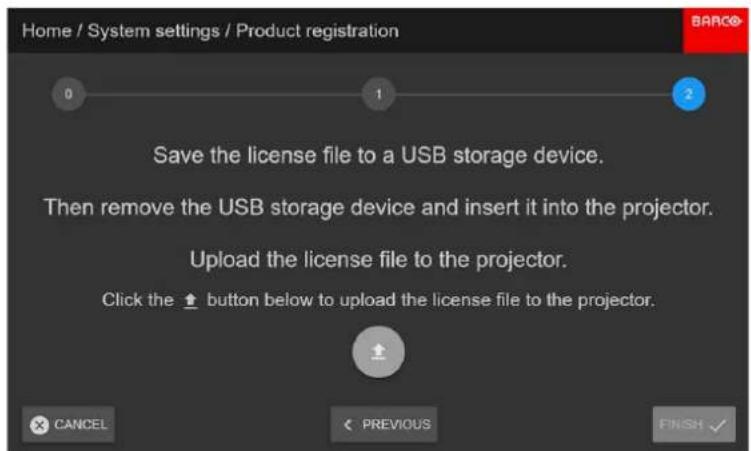
Image 8-10
- Click the Upload icon.
When the file is uploaded onto the projector, the Finish button will become enabled.
- Click Finish to finalize the registration procedure.
8.2 Communication
8.2.1 Remote control
8.2.1.1 Remote control - Broadcast address
Location and availability
- Menu: Settings > Communication > Remote control
- Access level: all
- Models: all
About broadcast address
Broadcast address is a common address that can be set on the projector. That can be "0" or "1". The broadcast address is '0'.
Any command coming from an RCU programmed with that common address will be executed.
How to change the broadcast address
- In the Communication menu, select Remote control.
Image 8-11 Communication menu, Remote Control
The Remote control menu is displayed.
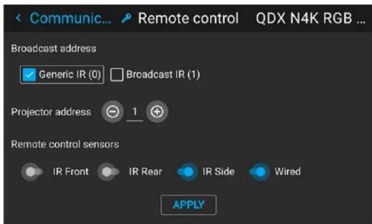
Image 8-12 Example of the Remote control menu
-
Select the desired broadcast address.
-
Generic IR (address 0)
-
Broadcast IR (address 1)
-
Select APPLY and confirm.
8.2.1.2 Remote control - Projector address
Location and availability
- Menu: Settings > Communication > Remote control
- Access level: all
- Models: all
About individual projector address
As more than one projector can be installed in a room, each projector should be separately addressable v an RCU or with a computer using serial communication. Therefore each projector has its own address. The factory default individual projector address is '0'.
When the address is set, the projector can be controlled with the RCU. Only addresses between 0 and 3 supported for the RCU.
Next to an individual projector address, each projector has also a broadcast address for group control.
How to change
- In the Communication menu, select Remote control.
Image 8-13 Communication menu, Remote Control
The Remote control menu is displayed.
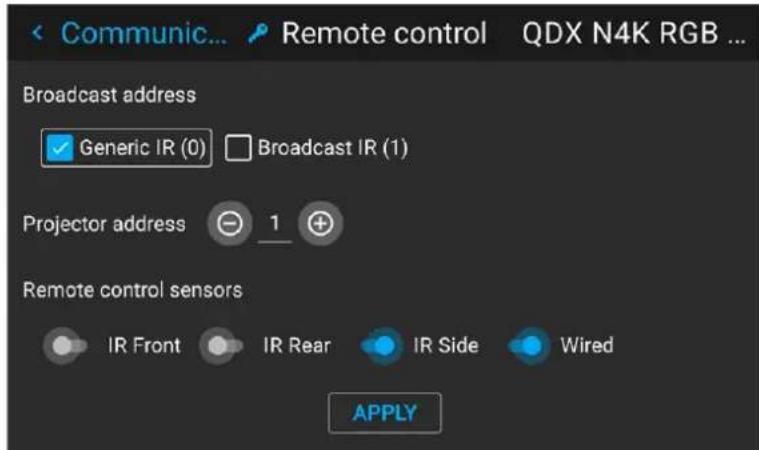
Image 8-14 Example of the Remote control menu
-
Select Projector address, enter the desired address and confirm.
-
Select APPLY and confirm to apply the changes.
From now on the projector will only listen to this new address and to its broadcast address.
8.2.1.3 Remote control - IR sensors
Location and availability
- Menu: Settings > Communication > Remote control
- Access level: all
- Models: all

An updated version of the Remote control is available on Pulse 2.6 and later. Update the project to the latest available version to have access to the Wired enable slider..
What can be done?
Every projector has a number of infrared (IR) sensors on different sides of the projector, as well as wired control options (via minijack and/or XLR). The number depends on the projector model. The IR sensors are wired options are used to interact with the IR signal originating from either the basic RCU or the Pulse F
However, when the projector is used in combination with other devices that emit or receive IR signals (e.g. 3D emitter), the different IR signals can interfere with each other and can cause undesired reactions. In the case, it is advised to disable a number of IR sensors.
The IR sensors are enabled by default. Each IR sensor can be individually disabled or enabled.

When all IR sensors are disabled, the projector will no longer respond to IR signals from the rem control.
The Pulse RCU can still be used, using the wired connector. See the projector user manual on h to connect the Pulse RCU using the wired connector.
How to disable
- In the Communication menu, select Remote control.
Image 8-15 Communication menu, Remote Control
The Remote control menu is displayed.
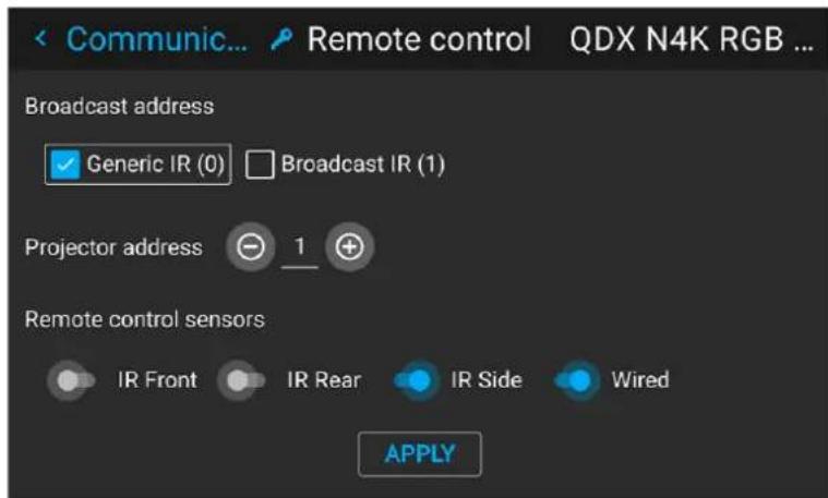
Image 8-16 Example of the Remote control menu
- To disable an IR sensor, disable the slider next to the undesired IR sensor.
- To disable the wired access to the Pulse RCU, disable the slider next to Wired.
- Select APPLY and confirm with OK to apply the changes.
8.2.2 Host name - Custom projector name setup
Location and availability
- Menu: Settings > Communication > Host name
- Access level: all
- Models: all
What can be done?
The default host name of the projector is the projector type along with the serial number of the projector "UDX-4K40-0123456789").
The host name can be changed to make the projector easier to spot in a network with multiple devices or projectors.
How to set a different Host name
- In the Communication menu, select Host name.
Image 8-17 Communication menu, Host name
The Host name menu is displayed.
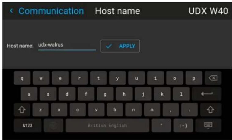
Image 8–18 Example of the host name menu
- Enter the Host name field and confirm.
The on-screen keyboard will be prompted.
-
Use the on-screen keyboard to change the Host name to the desired custom name.
-
Click Apply to save the updated host name.
8.2.3 Network setup
About a network connection
A network connection can be made via the LAN port, the HDBimpelt, or using the optional wireless module.
8.2.3.1 Introduction to a Network connection

DHCP
Dynamic host configuration protocol. DHCP is a communications protocol that lets network administrators manage centrally and automate the assignment of IP addresses in an organization's network. Using the Internet Protocol, each machine that can connect to the Internet needs a unique IP address. When an organization sets up its computer users with a connection to the Internet, an address must be assigned to each machine. Without DHCP, the IP address must be entered manually at each computer and, if computers move to another location in another part of the network, a new IP address must be entered. DHCP lets a network administrator supervise and distribute IP addresses from a central point and automatically sends a new IP address when a computer is plugged into a different place in the network.

IP
Internet Protocol. The network layer of TCP/IP. Required for communication with the internet.

Subnet mask
A number that is used to identify a subnetwork so that IP addresses can be shared on a local network.

Default Gateway
A router that serves as an entry point into and exit point out of a network. For example, a local network (LAN) may need a gateway to connect it to a wide area network (WAN) or to the Intern

MAC address
Media Access Control address. Unique hardware number, used in combination with the IP-address to connect to the network (LAN or WAN).
What should be set up for an Ethernet address?
Two ways can be used to assign an address:
- Use the Automatic setting so that an automatic address will be assigned.
- Manually assign an IP address, Net-mask (subnet-mask), (default) gateway address.
- Set the IP-Address field to the desired value. This must NOT be 0.0.0.0 for static IP-Address assignment. The IP address identifies a projector's location on the network in the same way a street address identifies a house on a city block. Just as a street address must identify a unique residence IP address must be globally unique and have a uniform format.
- Set the Subnet-Mask as appropriate for the local subnet.
- Set the Default-Gateway to the IP-Address of the local router (MUST be on the local subnet!) on the same network as this projector that is used to forward traffic to destinations beyond the local network. This must not be 0.0.0.0. If there is no router on the projector's local subnet then just set this field IP-Address on the subnet.
Security when using a network
The local network can be accessible from anywhere by anyone within the operating range of the (wireless) network, if the security settings of the (wireless) network are insufficient. If people with malicious intent acc the network, sensitive information may leak to outsiders, or the projector itself may be tampered with.
On the network side, Barco thus recommends the maximum amount of security for the network, in order to avoid this form of tampering. Some network devices may not be properly set for security when installed on the box. Make sure to read the provided user documentation of the network device to properly set up the necessary security settings of the (wireless) network.
On the projector side, Barco recommends to make a limited amount of specific users on the external tools. Barco provides (e.g. Pulse Prospector), and change all default passwords provided to strong passwords. For more information on user creation and password changing, please consult the Pulse Prospector user guide.

A strong password has a minimum of 8 characters and should be unique. The password should be a mix of upper case letters, lower case letters, numbers and special characters.
About LAN over WiFi
When the optional Wi-Fi module or Wi-Fi dongle is installed on the projector, the projector can be configured a way that it can access the network via Wi-Fi instead of a LAN cable.
For more information on how to install the Wi-Fi module, please refer to its installation manual.
About LAN over HDBaseT
When a LAN cable is connected to the HDBaseT, the HDBase™ menu will appear in the Settings menu. The projector can be configured in a way that it can access the network™ winsteBaseThe default LAN port.

For F40, F70, F80, Bragi, Balder and Medea, the F1DBasefe found on the connection panel.
For other projectors, the HDBase™ feature is only supported HDBaseT on the Pulse Quad Combo Input MKII.
8.2.3.2 Wired IP address - Automatic setup
Location and availability
- Menu: Settings > Communication > LAN
- Access level: all
- Models: all
How to automatically set up the IP address
- In the Communication menu, select LAN.
Image 8–19 Communication menu, LAN
The LAN menu is displayed.
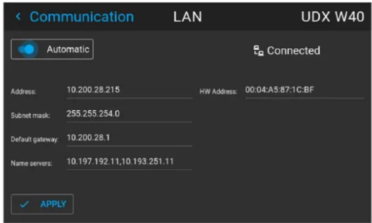
Image 8–20 Example of the LAN menu
- Enable the Automatic slider.
An IP address will be automatically assigned if it can make a connection to the network. When connected, it is indicated with the connection symbol and the indication Connected.
- Select APPLY and confirm.
8.2.3.3 Wired IP address set up - Manual setup
Location and availability
- Menu: Settings > Communication > LAN
- Access level: all
- Models: all
How to manually set up the IP address
- In the Communication menu, select LAN.
Image 8-21 Communication menu, LAN
The LAN menu is displayed.
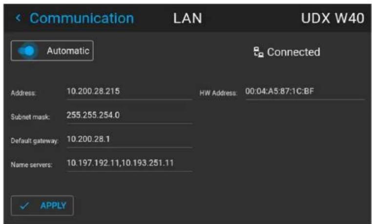
Image 8-22 Example of the LAN menu
- Disable the Automatic slider.
- Select the Address field and confirm.
An on-screen keyboard will be prompted.
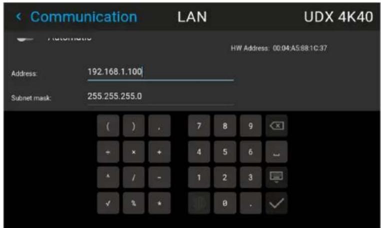
Image 8-23 Example of entering the IP address
- Enter the desired IP address and confirm using the √ symbol.
- Repeat the previous steps for all other fields in the LAN menu.
- Select APPLY and confirm.
When the connection is established, it is indicated with the connection symbol and the indication Connected.
8.2.3.4 Wi-Fi IP address - Automatic setup
Location and availability
- Menu: Settings > Communication > WiFi
- Access level: all
Settings
- Models: all
- Requirements: WiFi module or WiFi dongle
How to connect to a wireless network?
- In the Communication menu, select WiFi.
Image 8-24 Communication menu, WiFi
The WiFi menu is displayed.
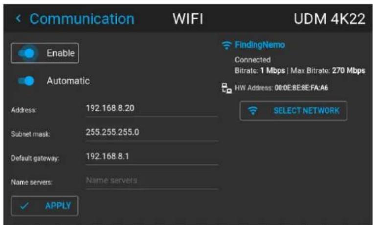
Image 8-25 Example of the WiFi menu
- Enable the Enable and Automatic sliders.

Tip: The Enable slider enables the Wi-Fi module. The Automatic slider enables automatic IP address assignment.
If the projector was previously connected with a wireless network, it will automatically try to reconnect this network. If the projector can connect to the network using this method, proceed to the last step in procedure.
- Select SELECT NETWORK and confirm.
The Select WIFI Network menu will be displayed.
- Select the desired network from the available list and confirm.
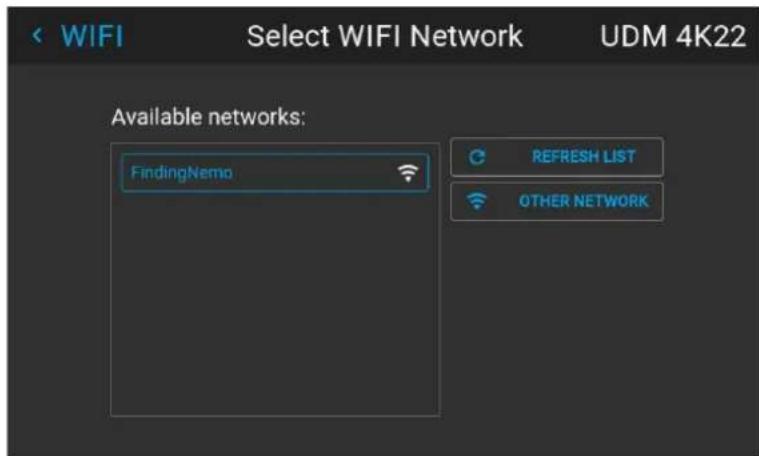
Image 8-26 Example of the available networks list.

Tip: If the desired wireless network is not in the list of available networks, or if the desired network is hidden by default, select OTHER NETWORK and confirm. An on-screen keyboard will be prompted. Fill in the details of the network using the on-screen keyboard.
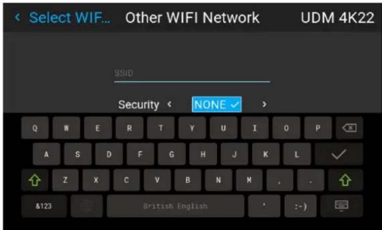
Image 8-27 Example of the entry form to search for other wireless networks
- Select Connect and confirm to connect to the selected network.
- If required by the chosen wireless network, fill in the user name and password, and confirm.

Tip: If the projector has already connected to this network in the past, the software will have remembered the user name and password.
If the filled in credentials are correct, an IP address will be assigned. Also, the term "connected" will be visible in the right side of the menu.
8.2.3.5 Wi-Fi IP address - Manual setup
Location and availability
- Menu: Settings > Communication > WiFi
- Access level: all
- Models: all
- Requirements: Wi-Fi module or Wi-Fi dongle
How to manually set up the Wi-Fi IP address
- In the Communication menu, select WiFi.
Image 8-28 Communication menu, WiFi
The WiFi menu is displayed.
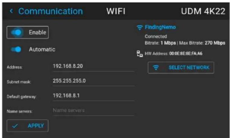
Image 8-29 Example of the WiFi menu
- Enable the Enable slider to enable the Wi-Fi module.
- Disable the Automatic slider in order to set the IP address manually.
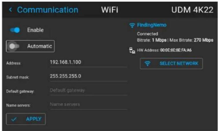
Image 8–30
- Select the Address field and confirm.
An on-screen keyboard will be prompted.
- Fill in the IP address using the on-screen keyboard and confirm using the √ symbol.
- Repeat the previous steps for the other fields in this menu.
- Select APPLY and confirm to save the manually entered IP address.
- Select the Select Network button, select the desired wireless network from the list and confirm.
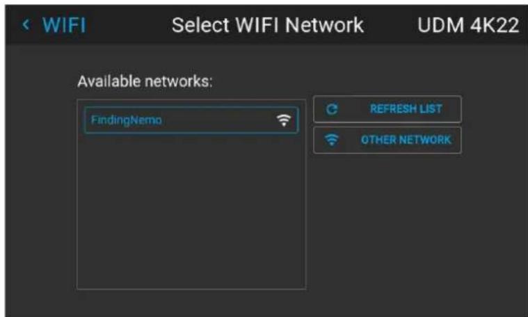
Image 8-31 Example of the available networks list.
- If required by the chosen wireless network, fill in the username and password and confirm.
If the filled in credentials are correct, the term "connected" will be visible in the right side of the men
8.2.3.6 LAN over HDBaseMP address - Automatic setup
Location and availability
- Menu: Settings > Communication > HDBaseT ^TM
- Access level: all
• Models: UDX, UDM, FS40, FL40, F70, Njord, Hodr, Borg, Balder - Requirements: HDBaseT™ input

Take into account that the HDBaseNetwork is unavailable if the projector is in either Standby mode or Standby ECO mode (whichever is available on the projector). ^TM HDBaseTas the main network connection, it is thus advised to disable standby mode. For more info, see "Auto standby", page 181.
How to automatically set up the IP address
- In the Communication menu, select HDBaseT ^TM .
Image 8-32 Communication menu, HDBaSET
The HDBase ^TM menu is displayed.
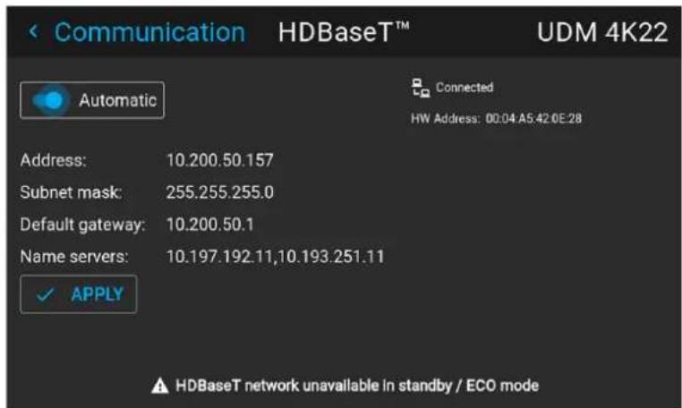
Image 8-33 Example of the HDBaseTenu
- Enable the Automatic slider.
An IP address will be automatically assigned if it can make a connection to the network. When connected, it is indicated with the connection symbol and the indication Connected.
- Select APPLY and confirm.
8.2.3.7 LAN over HDBaseMP address - Manual setup
Location and availability
- Menu: Settings > Communication > HDBaseT ^TM
- Access level: all
• Models: UDX, UDM, FS40, FL40, F70, Njord, Hodr, Borg, Balder - Requirements: HDBaseT™ input

Take into account that the HDBasNetwork is unavailable if the projector is in either Standby mode or Standby ECO mode (whichever is available on the projector). TM HDBasTas the main network connection, it is thus advised to disable standby mode. For more info, see "Auto standby", page 181.
How to manually set up the IP address
- In the Communication menu, select HDBase T^TM .
Image 8-34 Communication menu, HDBa5T
The HDBase ^TM menu is displayed.
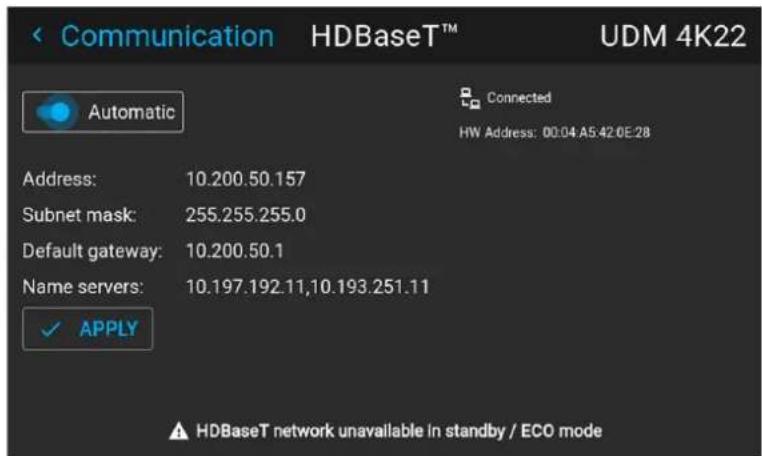
Image 8-35 Example of the HDBaseTenu
- Disable the Automatic slider.
- Select the Address input field.
An on-screen keyboard will be prompted.
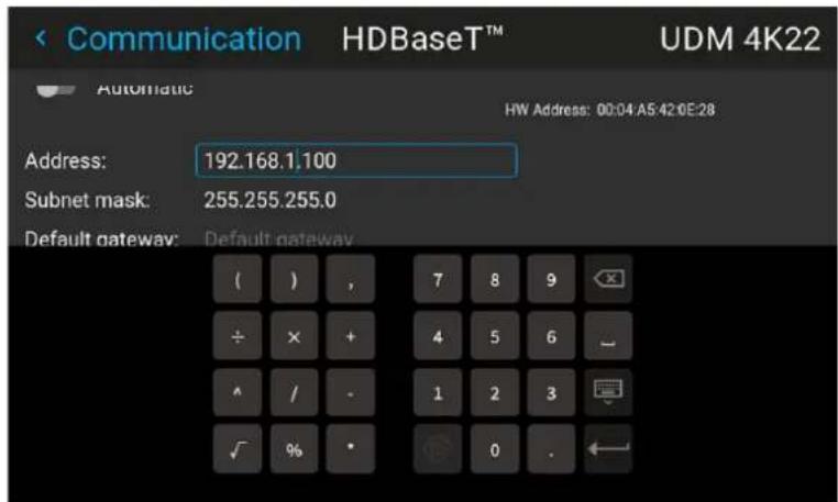
Image 8-36 Example of entering the IP address
- Fill in the IP address using the on-screen keyboard and confirm.
- Repeat the previous steps for the other input fields on the screen.
- Select APPLY and confirm.
When the connection is established, it is indicated with the connection symbol and the indication Connected.
8.2.4 DMX
Location and availability
- Menu: Settings > Communication > DMX
- Access level: all
• Models: QDX, UDM, UDX, I600, FL40, F70, F400, Bragi, Balder, Njord, Hodr - Requirements: DMX IN/OUT connectors
DMX control methods
By default, DMX over Ethernet (using Art-net) is available on projectors where DMX is allowed.
DMX over XLR (using DMX512) is only available under the following conditions:
- The communication panel on the projector has DMX IN/OUT XLR connectors.
- The optional Quad Combo input MKIII is installed on the projector.
Ways to control the projector via DMX
Connect a standard DMX cable equipped with an XLR connector to the DMX in port. The DMX out can be used to create a chain of DMX devices. One DMX universe can control up to 512 channels.
When using a DMX console and other automated lighting products compatible with Art-Net, the Ethernet network can serve as the link for DMX control. All DMX controls can be sent over the Ethernet cable. M universes are possible. This method allows a user to control more than 512 channels in the setup.
For a full list of all DMX channels, values and possible actions, see "DMX charts", page 229.
About the DMX menu
| DMX Feature | What can be done? |
| Connector type | Choose between DMX 512 (via XLR) and Art-Net (via Ethernet).If Art-Net is selected, Art-Net universe and Art-Net net become available. |
| DMX Art-Net Universe | If Art-Net is enabled, specify which DMX universe this projector belongs to. |
| DMX Art-Net net | If Art-net is enabled, specify the net channel. |
| DMX Mode T | Two different modes for DMX are available.Basic: A basic configuration where 2 channels are implemented.Extended: A full configuration, spread over 14 channels.For the full mapping of each used channel, refer to the DMX chart in the appendices. See “DMX charts”, page 229. |
| Start Channel | Before a projector can execute DMX commands, an address (named DMX address or Start channel) should be given to the projector.This address can vary from 1 to 512. |
| Auto shutdown | The projector can be forced to shut down after a certain time-out period if no DMX signals are available.Note: Value is set in minutes. |
| Channels If a | DMX device is connected, the settings per channel can be displayed by clicking theMonitor button ( ). |
| Reset for Max intensity | The Shutter and intensity can be changed via DMX Channel 1 (both in Basic and Extende mode).If no DMX signals are available, the intensity value can be reset to its default (maximum) value of 255 using the Max Intensity button). |
| Wake on DMX activity | When the projector is in Standby mode, the projector will wake up when it detects any activity on the DMX network over XLR.Available on Pule 2.5 or later, if the Pulse Quad Combo MKIII is installed. |
| Front XLR connector | On Pulse 2.5 or later, this has been moved to a separate menu. For more info, see “Controlling the front XLR connector”, page 182. |
How to set up DMX?
- In the Communication menu, select DMX.
Image 8-37 Communication menu, DMX
The DMX menu is displayed.
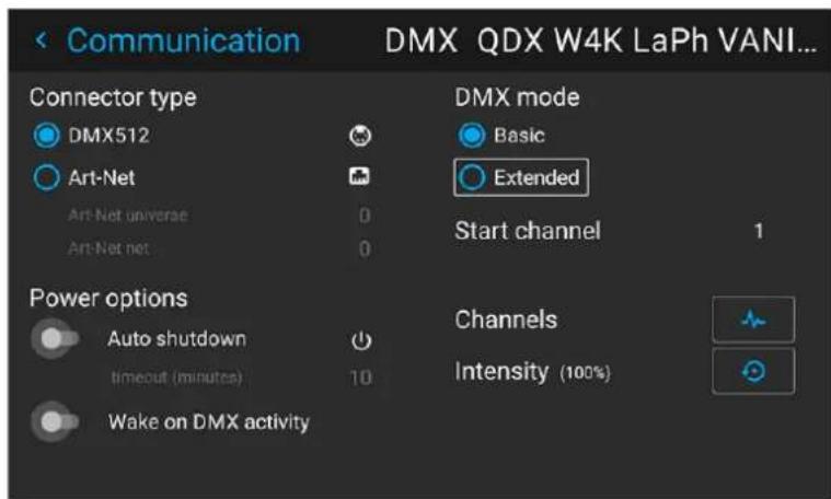
Image 8-38 Example of the DMX menu
- Choose the used Connector type.
- If Art-Net is chosen, determine the desired Art-Net Universe and Art-Net channel.
- Choose the desired DMX mode.
-
Choose the desired starting channel.
-
Choose whether or not the Auto power-down feature should be enabled. If enabled, determine the time-out.
-
Enable Wake on DMX activity if the feature is visible and the projector is connected to the DMX network using XLR.
8.2.5 PJLink
Location and availability
- Menu: Settings > Communication > PJLink
- Access level: administrator, service
• Models: QDX, UDM, UDX, I600 - Requirements: Pulse 2.4 or later
About PJLink
JBMIA PJLink is a unified standard for operating and controlling projectors using external "controller" computers.
The supported PJLink commands and how they apply to this projector is described in the appendix: "PJLink commands", page 241.

When PJLink is enabled on this projector, it will be compliant with the PJLink specification Version 2.00
What can be done
The following items can be configured on the Projector:
| Menu item Function | |
| PJLink Enable / disable slider | Enables or disables the PJLink protocol on the projector.This slider is disabled by default. |
| Authentication and Password | Authentication adds a layer of password protection between the controller and projector.When authentication is enabled, enter a valid custom password. When the controller then tries to access this projector, this custom password will have to be entered in order to control the projector.Note: The custom password can be:Up to 32 charactersOnly letters and numbers are allowed:: [0-9], [a-z] and [A-Z].No special characters are allowed. |
| Notification While notifications | cations are enabled and a valid controller address is filled in, all projector notifications will be sent to the IP address of the controller. |
| Controller address Location/IP address of the PJLink controller | |
How to activate PJLink
- In the Communication menu, select PJLink.
Image 8-39 Communication menu, PJLink
The PJLink menu will be displayed.
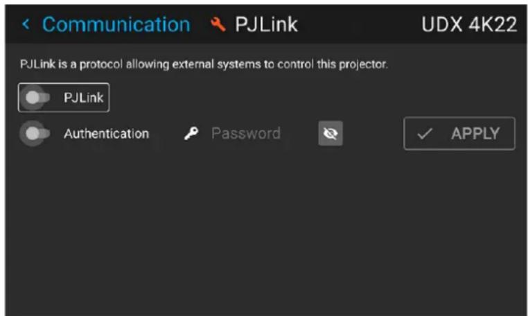
Image 8-40 Example of the PJLink menu
- Enable the PJLink slider.
The Notification options will become visible.
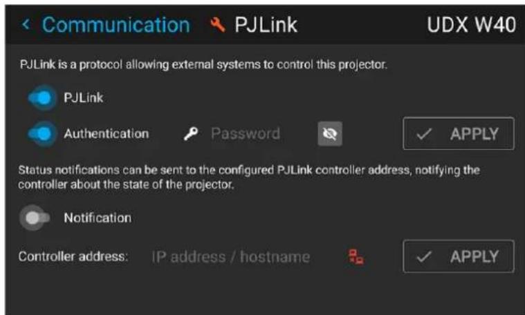
Image 8-41 Example of the PJLink menu with the Notification options visible.
-
To enable authentication, proceed as follows:
-
Enable the Authentication slider.
- Fill in a valid password and confirm. Use up to 32 characters in the range [a-z], [A-Z] and [0-9].
-
Select APPLY and confirm.
-
To enable notifications on the controller PC, proceed as follows:
-
Enable the Notification slider.
- Fill in the valid Controller IP address or host name for the controller PC and confirm.
- Select APPLY and confirm.
If a valid Controller address was filled in, the connection icon will change from red (disconnected) to white (connected).
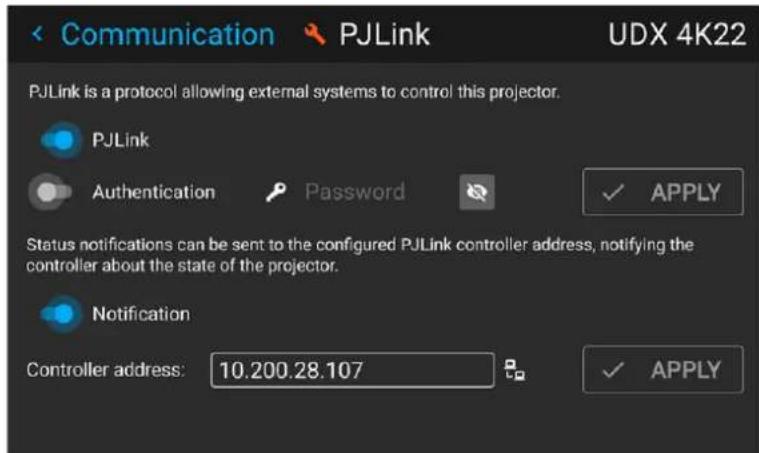
Image 8-42 Example of the PJLink menu while logged in and with a valid controller address filled in.

On Pulse 2.5 or later, the Login feature on the main menu of the Pulse OSD software can be used to log in as administrator or service technician. For more info on this, see "User authentication", page 26.
However, on Pulse 2.4 specifically, the PJLink menu was first made with its own login button to unlock the menu features. When using Pulse 2.4, use the login button to log in with administrator service technician access.
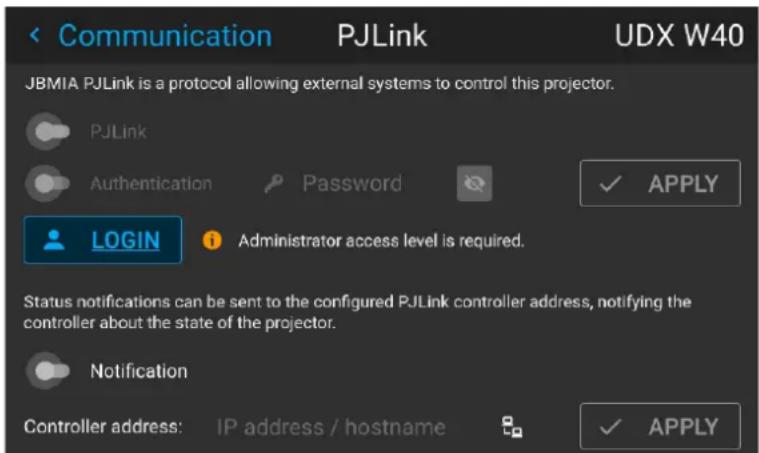
Image 8–43 Example of the PJLink menu in Pulse 2.4
8.2.6 GSM configuration
Location and availability
- Menu: Settings > Communication > GSM
- Access level: all
- Models: all
- Requirements: GSM module with SIM card
When to use the GSM menu
The GSM menu by itself does not have any functionality. The main purpose of this menu is to read out necessary data from the SIM card in the GSM module.
This information may be required when using specific connectivity functions (e. g. configuring the Insights Management Suite in a mobile-only setup).
About the SIM card PIN code
To configure the projector software with the installed SIM card for the first time, a correct PIN code (4 di must be entered.

The software cannot verify if the entered PIN code I correct. Make sure to enter the correct PIN code.

When the used SIM card is blocked, remove the SIM card from the GSM module and to insert the SIM card in a mobile phone. Do this so that the PUK code can be entered to unblock the SIM
How to activate
- In the Communication menu, select GSM.
Image 8-44 Communication menu, GSM
At first use, the GSM pin code input menu is displayed. If a correct PIN code has been entered in t it will not be necessary to enter the PIN code again.
- Enter the 4 digits of the PIN code and confirm.
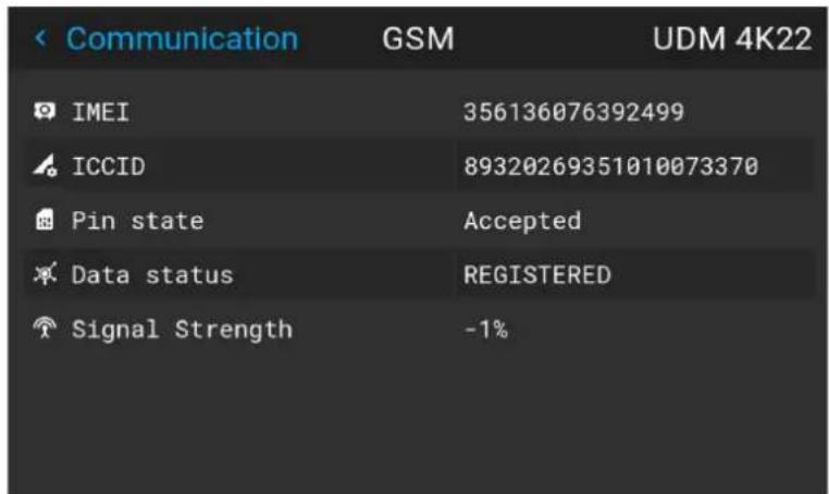
Image 8-45 Example of the GSM menu once the PIN code has been applied
8.2.7 Trigger outputs control
Location and availability
- Menu: Settings > Communication > Triggers
- Access level: all
• Models: QDX, I600, F40, F70, F400, Bragi, Balder
About the trigger outputs
There are a number trigger outputs on the projector (two or three, depending on projector model). The trigger outputs are located on the connection panel of the projector. The triggers can be used for controlling external equipment, like motorized screens, curtains, etc.
The trigger outputs can be individually set to active low or active high.

If the trigger outputs are loaded too heavily, there is a risk that the projector will go in reset mo and restart. This causes no damage to the projector, but is an undesirable response. This will also happen if the startup current for the external equipment is too high, even though the nominal power consumption is less than 0,5 A.
How to enable or disable
- In the Communication menu, select Triggers.
Settings
Image 8-46 Communication menu, Triggers
The Triggers menu is displayed.
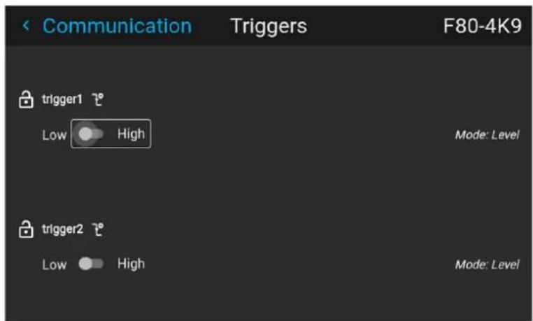
Image 8-47 Example of a Triggers menu
- Use the slider for each trigger individually to set them to "active low" or "active high".

The time of trigger output is defined via API code. Contact Barco support for detailed info.
8.3 User interface
8.3.1 Changing the User Interface language
Location and availability
- Menu: Settings > User interface > Language
- Access level: all
- Models: all
How to change the language of the user interface
1. In the User interface menu, select Language.

Image 8-48 Interface
The Language menu is displayed.
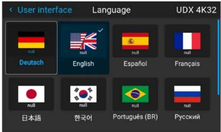
Image 8-49 Example of the Language menu
2. Select the desired language and confirm. Choose one of the following:
- German (DE)
- English (EN)
- Spanish (ES)
- French (FR)
- Japanese (JA)
- Korean (KO)
- Portuguese (PT-BR)
- Russian (RU)
- Chinese (ZH)
8.3.2 Themes
Location and availability
- Menu: Settings > User interface > Themes
- Access level: all
- Models: all
About Themes
Themes are used to apply a predefined functionality to the OSD display. There are two options: light or c. The default theme is dark.
Changing themes can be helpful in setups with low ambient lighting conditions. Choosing a Light theme in situation may put less strain on the eyes.
How to select a different interface theme
- In the User interface menu, select Themes.
Image 8–50 Settings menu, themes
The Themes menu is displayed.
- Select the desired theme and confirm.
If a different theme is chosen, the look-and-feel of the user interface will change.
8.3.3 Units (measurement) system setup
Location and availability
- Menu: Settings > User interface > Units
- Access level: all
- Models: all
About the used measurement systems
This menu can be used to change the default measurement. The following can be changed:
• Temperature: °C or °F. Default is °C.
- Distance: meters (m), centimeter (cm), feet (Ft) or inch (in). Default is meters.
How to set a different metric system
- In the User interface menu, select Units.
Image 8-51 Settings menu, units
The Units menu is displayed.
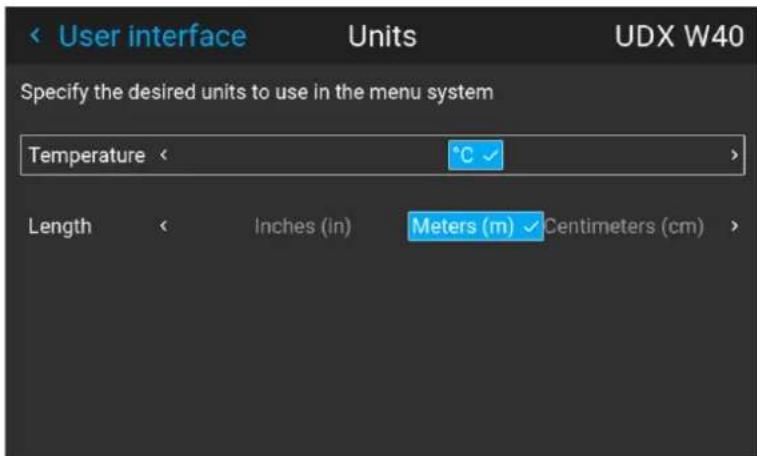
Image 8-52 Example of the Units menu
- Select the desired Temperature unit and confirm.
- Select the desired Length unit and confirm.
8.3.4 Controlling the backlight of the LCD Display
Location and availability
- Menu: Settings > User interface > Backlight
- Access level: all
- Models: all
What lighting can be controlled?
The backlight of the LCD display will turn off after five minutes by default. this feature can be disabled. Alternatively, the time interval can be changed to another preset, or a custom entered value.
Stealth Mode
Alternatively, Stealth Mode can be activated instead. By activating this mode, the backlight of the LCD, the backlight of all the buttons of the keypad and the indication LEDs for the LAN and HDbaseT inputs will be disabled.
Stealth Mode can also be enabled or disabled by pressing the OSD button on the remote control for 3 seconds.
How to set the backlight
- In the User interface menu, select Backlight.
Image 8-53 Settings menu, backlight
The Backlight menu will be displayed.
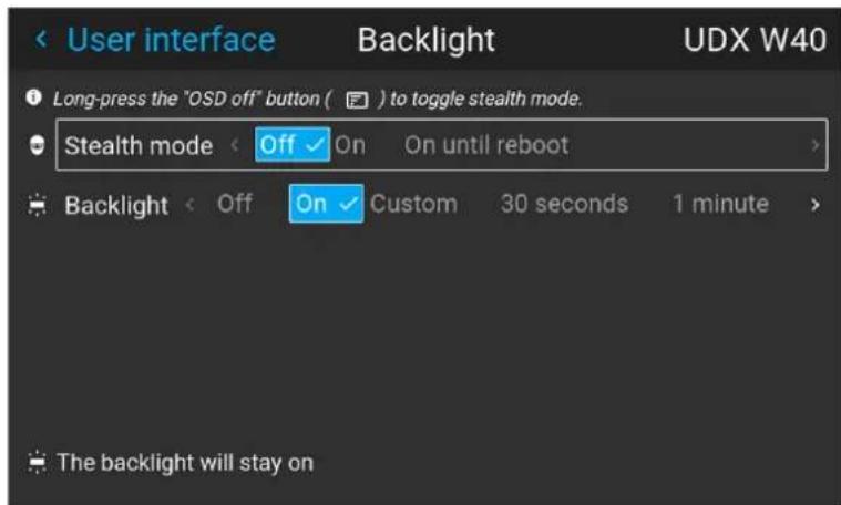
Image 8-54 Example of the backlight menu
-
Choose the desired Stealth mode:
-
Off: Stealth mode will be disabled.
- On: Stealth mode will be on.
-
On until reboot: Stealth mode will remain on until the next reboot of the projector.
-
Choose how long the backlight will remain on. Choose one of the following:
-
Off: The Backlight will turn off and remain off.
- On: The backlight will turn on and will remain on.
- Any value between 30 seconds and 1 hour: The backlight will turn off and remain off after the chosen timestamp.
- Custom: Remembers the previous chosen custom value (if any).
8.4 Date and time
8.4.1 Date and time setup - automatically
Location and availability
- Menu: Settings > Date and time
- Access level: all
- Models: all
About date and time
The date and time setting can be set automatically via an NTP server based on region and city location.

Date is displayed by default as: day / month / year.
Time is displayed by default as: hour : minutes : seconds, in the 24-hour clock.
To set date and time automatically
- In the Settings menu, select Date and time.
Image 8-55
The Date and time menu will be displayed.
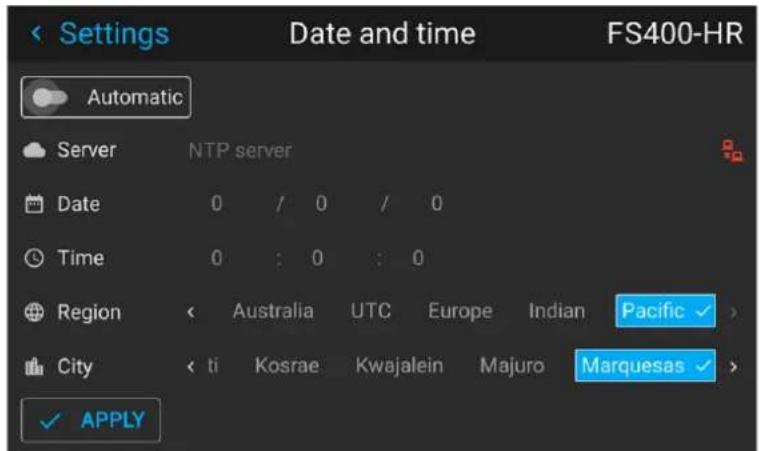
Image 8-56 Example of the Date and time menu
- Enable the Automatic slider.
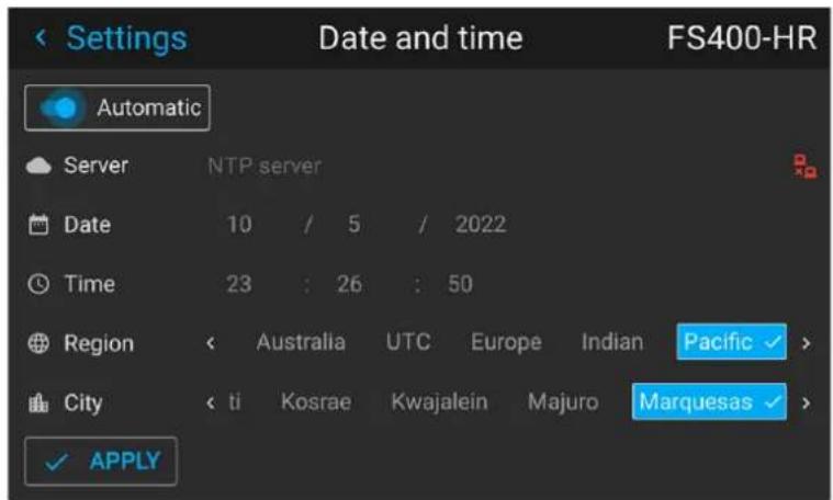
Image 8-57
- Select Server and confirm.
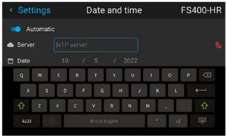
Image 8–58
- Enter the hostname or the IP address of the NTP server and confirm.

Tip: In case the projector cannot connect to an external NTP server although the server can be PINGed, the connection is blocked by the local firewall policy. Contact the local IT system administrator.
In case the connection is successful, a green icon appears at the right side of the server line.
- Select the desired Region from the list and confirm.
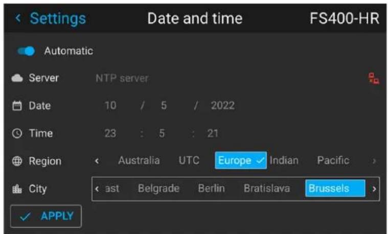
Image 8–59
The list of cities is updated according the selected region.
- Select the desired City from the list and confirm.
- Select Apply and confirm.
8.4.2 Date and time setup - manually
Location and availability
- Menu: Settings > Date and time
- Access level: all
- Models: all
About date and time
The date and time setting can be set manually or automatically via an NTP server based on region and location.

Date is displayed by default as: day / month / year.
Time is displayed by default as: hour : minutes : seconds, in the 24-hour clock.
How to set time manually
- In the Settings menu, select Date and time.

Image 8–60 Settings menu, Date and time
The Date and time menu will be displayed.
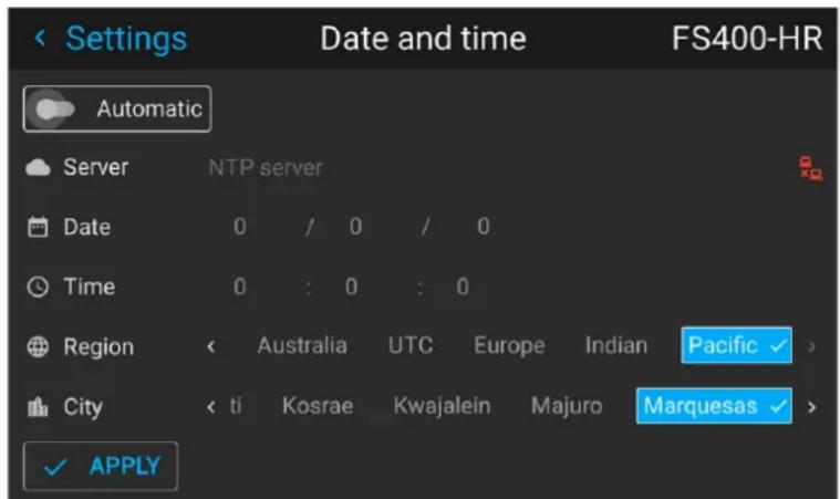
Image 8-61 Example of the Date and time menu
- Disable the Automatic slider.
- Select Date
The Date dialog is prompted. The active day is selected by default.
- Slide the Day, Month and Year slider up or down until the desired date is obtained.
or
Alternatively, use the up, down and OK buttons on the RCU or control panel until the desired date is obtained.
- Select Time.
Settings
The Time dialog is prompted. The active time is selected by default.
- Slide the Hour, Minute and second slider up or down until the desired time is obtained.
or
Alternatively, use the up, down and OK buttons on the RCU or control panel until the desired time is obtained.
- Select Apply and confirm.
8.5 Scheduler
8.5.1 About the projector scheduler
Location and availability
- Menu: Settings > Scheduler
- Access level: all
- Models: all

From Pulse 2.5 onward the Scheduler can be found in the Settings menu. In older versions, the Scheduler menu can be found directly in the main menu.
About the scheduler
The projector scheduler allows the user to automate the weekly schedule of the projector. This includes:
• Powering up the projector
- Selecting and activating a predefined projector profile.
• Powering down the projector
How to open the scheduler
- In the Settings menu, select Scheduler.
Image 8-62 Main menu, Scheduler menu icon
- The current scheduler will be displayed.
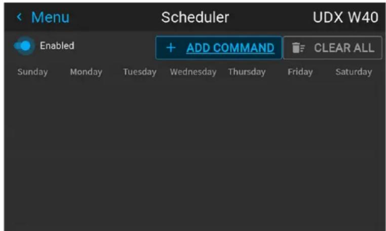
Image 8-63 Example of a cleared Scheduler menu

Make sure the Enabled slider is toggled on. If not, none of the items in the scheduler will trigger.
8.5.2 Adding a new command in the scheduler
How to add a new command
- In the Scheduler menu, select Add Command.
Settings
The Add Command page is displayed.
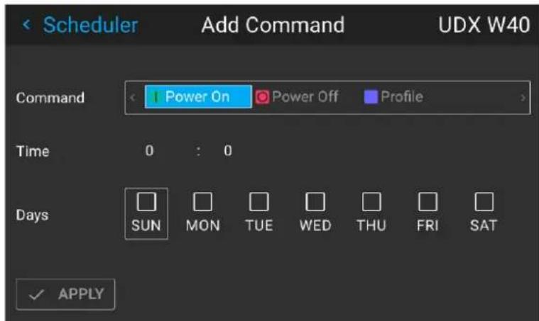
Image 8-64 Example of the Add Command window
- Select the type of command to be added. The following options are available:
a) Power On (ON mode).
b) Power Off (Ready and or Standby mode).
c) Activate a projector profile.

Tip: In order to activate a projector profile in the scheduler, a minimum of one projector profile will need to be configured beforehand. If no profile is available, the "Profile" option will not be available in the "Add Command" window.
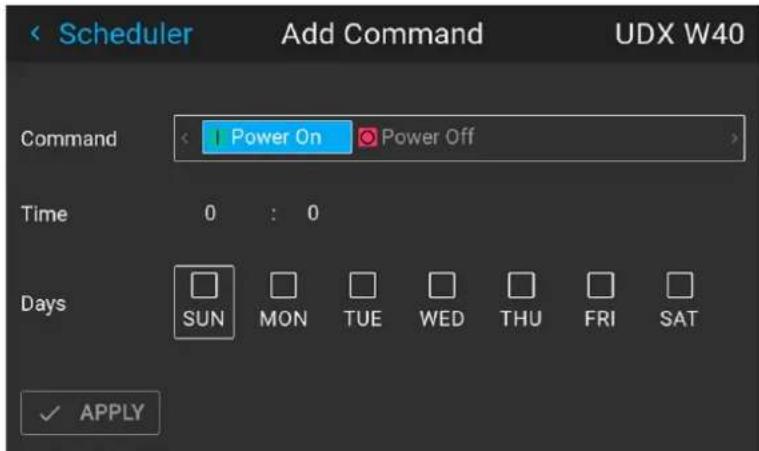
Image 8-65 Example of the Add Command window without any Projector Profiles configured
For more info on creating Projector Profiles, see "Projector profiles", page 129.
If Profile is selected, the currently available projector Profiles will be listed in the menu.
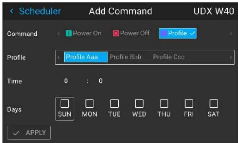
Image 8-66 Example of the Add Command window with the available profiles listed
- If Profile is selected, choose the desired profile to activate.
- Select the desired Time the command will need to activate (in hours and minutes of the day).

Note: Make sure the projector time is correctly configured. For more info, see "Date and time setup - automatically", page 171 and "Date and time setup - manually", page 173.

Tip: If the hour and minute marker is selected, a time slider will pop up. Use the hours and minutes sliders to select the desired timeframe and confirm.
- Select the desired days of the week when this command will need to activate. Use the arrow keys to select the desired days and confirm.
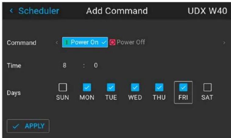
Image 8-67 Example of the Add Command menu with command, time and days of the week selected.
- Click Apply to add the new command to the scheduler.
The new command is added to the Scheduler.
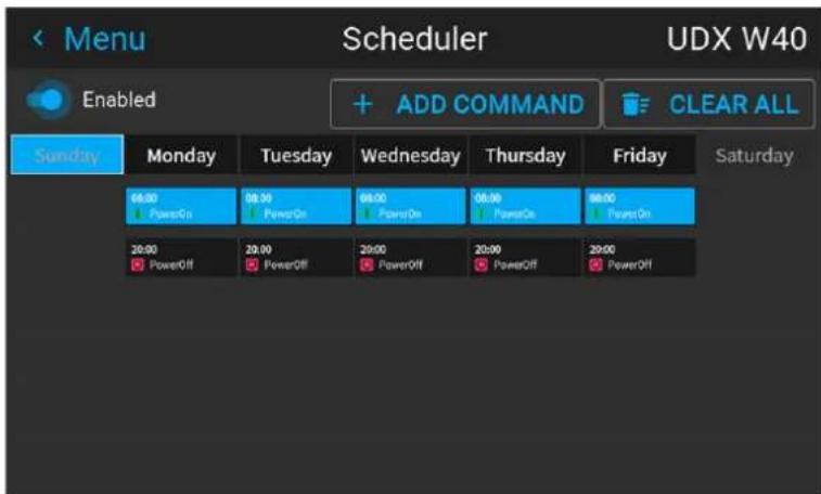
Image 8-68 Example of the Scheduler menu, with Power On being added.
8.5.3 Edit or Delete a command
How to edit or delete a command
- In the Scheduler menu, select and confirm an existing command.
The Edit Command window will be prompted.
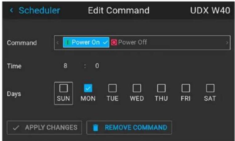
Image 8-69 Example of the Edit Command window
- Edit the desired settings of the Command.
- Once all changes have been made, select the Apply Changes button and confirm.
- If the command should be deleted instead, select Remove Command button and confirm.
8.5.4 Clearing the scheduler
How to clear up the entire scheduler
- In the Scheduler menu, click Clear All.
A warning dialog will be prompted, asking to confirm the clearing of the entire schedule.
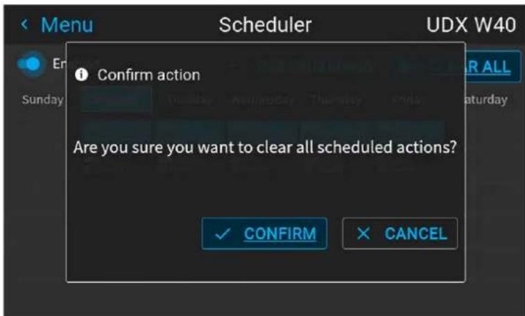
Image 8–70 Example of the warning dialog
- Confirm the action by selecting Confirm and confirm.

Note: If the Clear All button is clicked by accident, click Cancel instead to cancel and return to the Scheduler menu.
All actions in the Scheduler will be deleted.
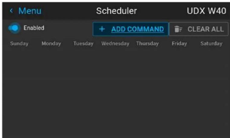
Image 8-71 Example of a cleared Scheduler menu
8.6 Power settings
About the power saving features
In the aspect of continuous improvement, Barco has added several power saving features to the projector, which will extend the lifetime of the projector and light source in particular.
8.6.1 Auto dimming
Location and availability
• Menu: Settings > Power > Auto dim
- Access level: all
- Models: all
About Auto dimming
When enabled the light source will be dimmed to 50% when:
- no source with active signal is connected to the projector,
• the OSD is not being projected, and - no test pattern is currently active.
How to set Auto dimming?
- In the Power menu, select Auto dim.
Image 8-72 Power menu, Auto dimming
The Auto dim menu is displayed.
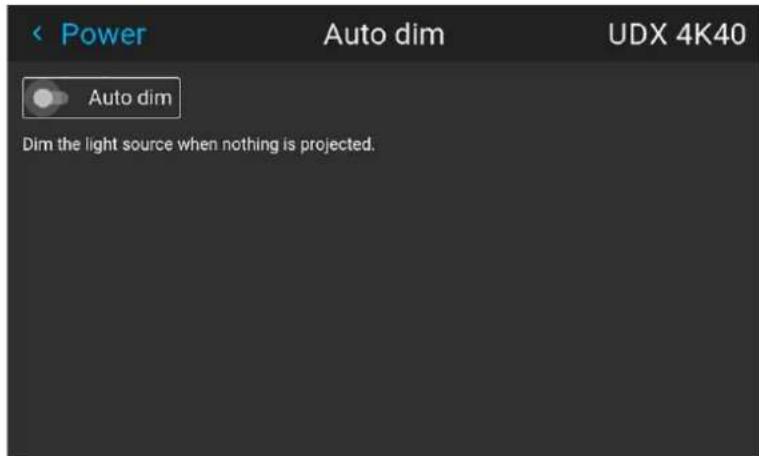
Image 8-73 Example of the Auto dim menu
- Enable or disable the Auto dim slider to respectively enable or disable the Auto dimming feature.
8.6.2 Auto light source off
Location and availability
- Menu: Settings > Power > Auto light source off
- Access level: all
- Models: all
About Auto light source off
When enabled, the projector will transition to Ready mode after a configurable time-out period when:
- no source with active signal is connected to the projector,
• the OSD is not being projected, and - no test pattern is currently active.
Most of the projector features will remain available while in Ready mode.
How to configure Auto dimming?
- In the Power menu, select Auto light source off.
Image 8-74 Power menu, Auto light source off
The Auto light source off is displayed.
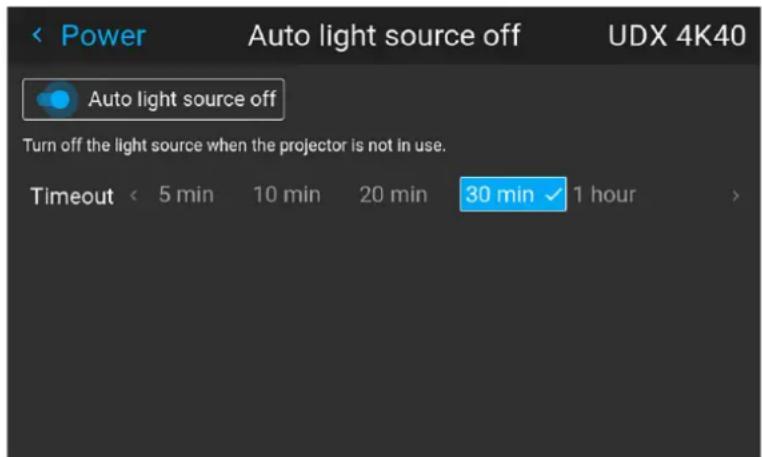
Image 8–75 Example of the Auto light source off menu
- Enable or disable the Auto light source off slider to respectively enable or disable this power saving feature.
- When enabled, select the time-out period after which the light source will be turned off.
8.6.3 Auto standby
Location and availability
- Menu: Settings > Power > Auto standby
- Access level: all
- Models: all
About Auto standby
When the projector is in Ready mode and is not actively being used (e.g. browsing through the projector software), the projector will transition to either Standby mode or ECO standby mode after a configurable tir out period.
The difference between the Standby and Standby ECO mode is the following:
- Standby mode: After a set time-out, the projector disables most functionality to save power, safe the communication options. This allows the projector to be awoken either using the local keypad, the RCU remotely using Pulse Prospector or automation controllers (e.g. using DMX).
- Standby ECO mode: After a set time-out, the projector disables almost all functionality to save power, safe a single small wake-up controller. This allows the projector to be awoken only using the local keypad or the RCU, or by sending a “Wake on LAN” package to the MAC address of the projector. The project can not be awoken using other methods.
Availability standby modes
Depending on the projector model, Standby mode, ECO Standby mode or both modes will be available. The availability is as follows:
- Standby mode only: UDX
- Standby ECO mode only: F40, F70, Bragi, Balder
- Both modes: QDX, UDM, I600, F400, Njord, Hodr
How to configure standby mode?
- In the Power menu, select Auto standby.
Image 8–76 Power menu, Auto standby
The Auto standby menu off is displayed.
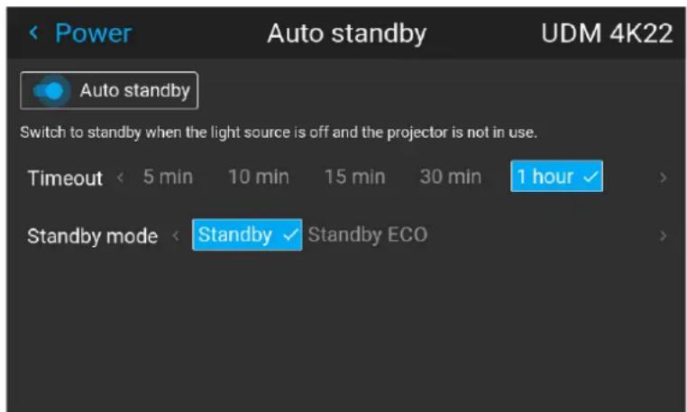
Image 8–77 Example of the Auto standby menu, with both modes available
- Enable or disable the Auto standby slider to respectively enable or disable this power saving feature.
- Select the time-out period after which the projector will go into standby or standby ECO mode.
- If available on the projector model, choose the desired version of the Standby mode: regular Standby mode, or Standby ECO mode.
8.6.4 Controlling the front XLR connector
Location and availability
- Menu: Settings > Power > Front XLR
- Access level: all
• Models: QDX, UDM, UDX, Njord and Hod
- Requirements: Pulse 2.5 or later

In older software versions, the front XLR feature can be found in the DMX menu, under Settings > Communication > DMX.
About the front XLR connector
There is a 4-pin XLR connector located on the front side of the projector, underneath the lens holder.
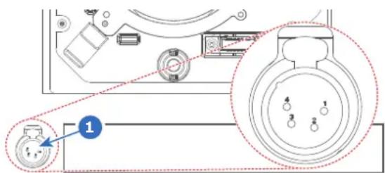
Image 8-78 Location of the XLR connector
The front XLR connector can be used to connect with peripheral devices. These can range from the motor rigging frame, an external mechanical shutter or other XLR-powered devices.

CAUTION: multiple peripheral devices can be connected if an XLR splitter is available. However, take into account that the maximum allowed load on the front XLR connector is 2 A.
Pinout of the front XLR connector
4-pin XLR connector
| Pin | Description |
| 1 | Earth |
| 2 | Data- |
| 3 | Data+ |
| 4 | VCC |
Powering the front XLR connector
The front XLR connector is enabled by default and set at 24 volts. When enabled, the output voltage level be set to 0 V, 12 V or 24 V..
The output voltage may depend on the application or peripheral used. All peripherals supplied by Barco ru 24 V.
How to enable or disable?
- In the Power menu, select Front XLR.
Image 8–79 Power menu, DMX
The Front XLR menu is displayed.
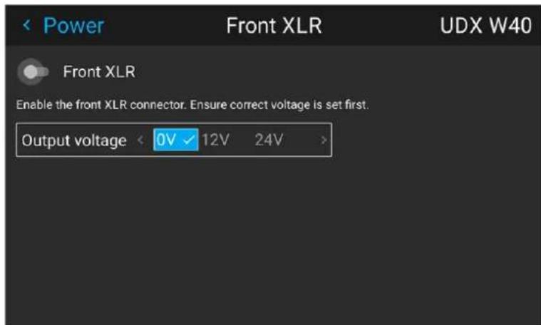
Image 8–80 Example of the Front XLR menu
- Toggle the Front XLR slider to the desired position.
- When enabled, select the desired Output Voltage and confirm.

Note: Due to technical reasons, if the motorized rigging frame is connected to the XLR connector, it is mandatory to put the voltage to 24V.
8.7 System
8.7.1 Setting up the external cooler
Location and availability
- Menu: Settings > System > Cooling
- Access level: all
- Models: UDM, UDX
- Requirements: External cooler
Using the external cooler
Using the Cooling menu, choose between the following cooling methods:
- Internal: Use only the internal cooling system of the projector (default).
- External: Use only the external cooling system of the projector. This method is preferred when the cooler is in a different location than the projector and the projector should operate in “silent mode”.
- Mixed: Use both the external and internal cooling. Can be used to extend the lifetime of the internal cooler of the projector.
How to set up the external cooler
- In the System menu, select Cooling.
Image 8–81 Installation menu, Cooling
The Cooling menu is displayed.
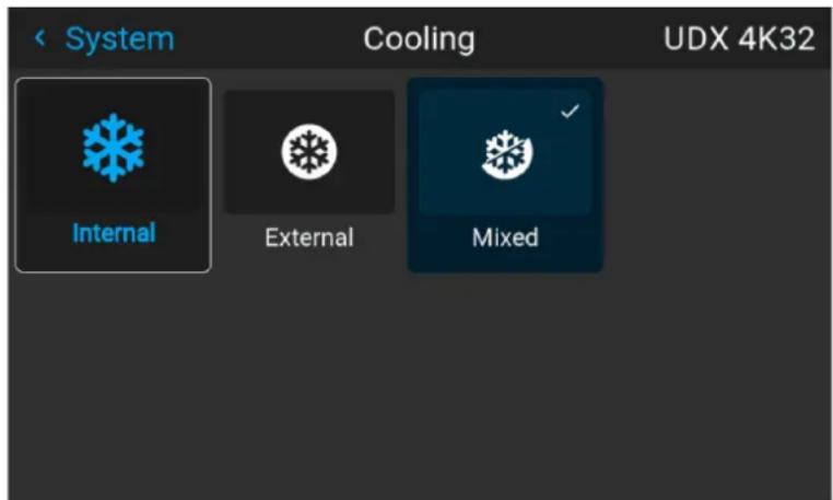
Image 8–82 Example of the cooling menu
- In the Cooling menu, select the desired cooling option and confirm.

Note: After changing the settings, it can take up to 1 minute for the changed settings to take effect.
8.7.2 Operational mode
Location and availability
- Menu: Settings > System > Operational mode
- Access level: all
- Models: QDX, UDM, I600, F80, UDX 4K40, UDX W40, UDX U40, UDX U45LC
About operational mode and the trade-off triangle
Using any projector comes with a trade-off triangle between brightness (light source power), cooling (fan speed and noise) and ageing (lifetime of the projector components). When going for the maximum in one these three points in the triangle, the other two will inevitably be sacrificed. This means the following:
- Going for maximum brightness on the projector comes at the cost of fan noise (running at maximum speed), and an increased ageing of the projector components (e.g. the light source).
- Going for the “silent” option, makes fans run at lower speeds (thus less noise), but comes at the cost of the light source not being able to run in its brightest mode, and may cost in lifetime (due to insufficient cost).
- Going for a “long lifetime” mode will come at a cost of not being able to run at maximum brightness and will have a certain level of fan noise.
Each projector manufacturer predetermines what the optimal location is in the trade-off triangle for the average usage of the projector so that brightness, lifetime and noise can be on an optimal level, and does allow much wiggle room from this optimal location.
However, on certain models Barco allows the user to take a certain level of control in this trade-off triang. This level of control can be found in the Operational mode menu feature.
Depending on the use-case of the projector, an Operational mode can be selected which more fits the installation's needs, while a smart monitoring algorithm in the background keeps on balancing and optimizing between illumination output power, minimal noise level and optimized temperature household.
Take into account that the implementation of this feature differs in each projector model.

Take note that the fan speed will never be lower than 30%, regardless of chosen mode or light source power.
Implementation on UDX
In more recent years, Barco has added 40k and 45k lumens variants to the UDX family lineup. The incre brightness brings this family of projectors on the edge of the trade-off triangle. For this reason, the Operat mode was introduced on these specific models. On these models, it works as follows:
- "Normal mode": This is the standard mode will force the fans to work at a speed corresponding to the light source power.
- "Silent mode": This mode will automatically adapt the fans to work at a lower speed, while still in accordance to the light source power.
For example, at 80% light source power, “Silent mode” can result in an audible difference of 4 dBA when compared to “Normal mode”.
Implementation on UDM
The following presets are available:
- "Normal mode": This is the standard mode delivering highest possible brightness while ensuring a life time of 20 000 hours and keeping the noise level around 48 dBA.
- "Silent mode": controlling maximal fan speed staying 47 dBA.
Implementation on 1600
The following presets are available:
- "Normal mode": This is the standard mode delivering highest possible brightness while ensuring a life time of 20.000 hours and keeping the noise level below 40 dBA.
- "Long Life mode": Bringing the lifetime to 40.000 hours by carefully balancing between cooling and output power.
- "High brightness mode": Offer maximum brightness under all ambient conditions.
Implementation on QDX
The following presets are available:
- "Normal mode": This is the standard mode delivering highest possible brightness while ensuring a life time of 20.000 hours and keeping the noise level below 40 dBA.
- "Long Life mode": Bringing the lifetime to 40.000 hours by carefully balancing between cooling and output power.
How to change the operational mode of the projector
- In the System menu, navigate to Operational mode.
Image 8–83 Maintenance menu, operational mode
The Operational Mode menu is displayed.
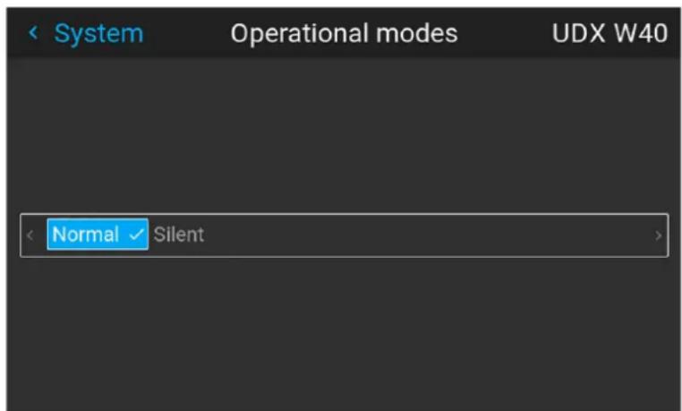
Image 8–84 Example of the Operational modes menu
- Choose the desired operational mode.
- Navigate to the Illumination menu and update the desired light output, depending on the chosen operational mode.

Note: If the light source cannot sustain the desired power, it will automatically be reduced to a power level that's sustainable for the light source and the chosen cooling power.
8.7.3 Capture mode
Location and availability
- Menu: Settings > System > Capture mode
- Access level: all
• Models: QDX, UDM, UDX
Why use capture mode?
Various technical features are used inside the projector to display the best possible image on the projected surface. However, in expositions and setups where visitors are expected to film or take pictures of the projected surface, some of these technical features may have side-effects on the captured footage, such as solarization.
Settings
Enabling Capture mode feature disables some of the technical features of the projector that are known to cause solarization and gives the visiting audience an experience they can “capture” and post on social me without worries.
How to enable Capture mode
- In the System menu, click Capture mode to toggle between On and Off.
Image 8-85 System menu, Capture mode disabled Image 8-86 System menu, Capture mode enabled
8.8 Lens features
Location and availability
- Menu: Settings > Lens features
- Access level: all
- Models: all
What can be done?
In order to prevent unintentional lens adjustments, especially after e. g. a completed setup and adjustment, there is a possibility to disable certain lens adjustment functions. These functions are directly accessible via the remote control, and can by that easily be adjusted by accident.
Depending on projector model and lens type, not all features may be available (e. g. no zoom on non-motorized lenses). The maximum list of lens features is the following:
• Vertical lens shift
- Focus
- Zoom
- Iris illumination
- Iris lens
• Horizontal lens shift
How to enable/disable
- In the Settings menu, select Lens Features.
Image 8–87 Settings menu, Lens features
The Lens features menu is displayed.
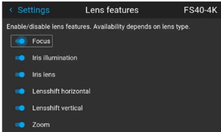
Image 8–88 Example of the lens features menu, here with all options available
- Enable or disable the desired lens features.
8.9 Maintenance
8.9.1 Factory reset
Location and availability
- Menu: Settings > Maintenance > Factory reset
- Access level: all
- Models: all
What can be done?
All settings and values on the projector can be reset to its default values. This can be done for one or setting domains separately, or all settings together (factory reset).
What are the factory settings?
The following settings are the default factory settings:

All factory settings are listed, regardless of the projector model, or user level access rights. If an option in this list is not present on the current projector, the feature is not available on the current model or not enabled for the current user.
| Option / Domain | Setting Factory setting | |
| GPIO Triggers All | triggers set to “active low” | |
| DMX DMX Mode | Basic | |
| Start Channel 1 | ||
| Auto power downArt-netXLR Connector | Disabled | |
| GSM | PIN State | Unconfirmed |
| Illumination | Power | 100%^11 |
| IR power | 100%^1 | |
| Constant light output (CLO) | Disabled | |
| ImageActuator | 4K Actuator enabled / disabled | Enabled |
| Blend | Blend / Mask sizeBlack Level | Disabled, all value to zero |
| Black Level FilesBlend Files | Disabled.Note: All uploaded blend and black level files will be deleted | |
| (Image) Capture | Camera | Camera disabled |
| Laser range finder | stored measurements erased.Tolerance set to 0 m.Reference distance cleared to “not set” | |
| Connectors | Signal range | Auto |
| Color space | Auto | |
| EDID | Default EDID for projector typeNote: All uploaded custom EDID files will be deleted. | |
| Image adjustments override Disabled | Overrides reset to mid values and auto gamma. | |
| Convergence Electronic Convergence All values to zero | ||
| Display Display mode AutoStereo | ||
| (Image) Features | Contrast mid value | |
| Brightness mid value | ||
| Saturation mid value | ||
| Sharpness mid value | ||
| Gamma mid value, auto | ||
| Digital Shift and Zoom | Disabled, set to mid values | |
| Cropping | Off | |
| Aspect Ratio | 16:9 | |
| Scaling | Fill Aspect ratio | |
| Orientation | Orientation | Table, Front |
| RealColorTM | P7 RealcoloTM | all set to native |
| Resolution | Output Resolution | 4K UHD (4K devices)WQXGA (W devices)WUXGA (U devices) |
| Source | Source files | Standard |
| 3D (Stereo) | Sync delay | 0 μs |
| Swap eye | Off | |
| Dark time | lowest value available | |
| Test patterns | Test Patterns | Off, none selected |
| Custom Test Patterns | Upload disabledNote: All uploaded custom test pattern will be deleted | |
| “No signal” image | Black image selected.Note: Uploaded custom “no signal” images will be deleted. | |
| Tilted brightness | Tilted brightness uniformity correction | Disabled, all values reset to 0 |
| Uniformity | DynaBlack Off | |
| Warp | Screen size | 5120x3200 / 2560x1600 |
| 4 cornerBow | Warp disabled, no warp | |
| Warp files | DisabledNote: all uploaded warp files will be deleted | |
| Linked services | Linked CLO | Disabled |
| Network | LAN | Automatic settings, stored manual settings removed |
| HDBaseT Automatic settings, stored manual setting removed | ||
| Hostname Projector family - model - serial number (e.g. “UDX-4K40-0123456789”) | ||
| Remote control Generic IR (0), projector address 0All IR sensors enabled | ||
| Optics High Contrast Off | ||
| PJLink PJ-Link Disabled | ||
| Peripheral | Settings for External Cooler | Cooling mode set to internal. |
| Settings for Motorized Frame | All values to mid value | |
| Profiles | Settings for projector profiles | All profiles will be deleted, presets will be cleared |
| Scheduler | Weekly schedule | Disabled, Schedule is fully cleared. |
| Screen | Screen luminance unit | nits |
| Screen Luminance | 400 | |
| HDR Boost | 1.0 | |
| System | Auto dim | Enabled |
| Auto light source off | Disabled, timer set to 10 minutes. | |
| Auto standby Mode / ECO standby (depending on availability) | Disabled, default mode depends on projector type. | |
| Operational Mode | Normal | |
| Source preview | Disabled | |
| Time | Time server | Automatic disabled, NTP server removed |
| Date | 0 / 0 / 0 | |
| Time | 0 : 0 : 0 | |
| Region / City | UTC | |
| User | User profiles | Only default users remain |
| Capture mode | Disabled | |
| User interface | Theme | Dark |
| Units - Temperature | °C | |
| Units - Length | Meters (m) | |
| Language | English | |
| Backlight - Stealth ModeBacklight - Time-out | Off5 minutes | |
| Custom LCD Splash image Images up | uploaded by external tools (e.g. Pulse Prospector) are removed. Images uploaded using the OEM partner tool provided by Barco are not removed. | |
How to reset all projector settings
- In the Maintenance menu, select Factory reset.
Image 8-89 Settings menu, factory reset
The Factory reset menu is displayed.
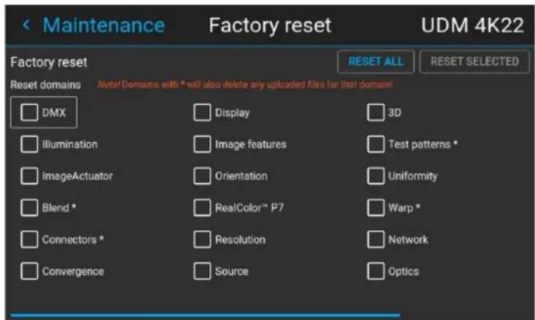
Image 8–90 Example of the Factory reset menu
- Select RESET ALL and confirm when prompted.

Take into account that a factory reset will delete all uploaded files (Flex licenses, custom warp file custom test patterns, etc).
How to reset one or more projector settings
- In the Maintenance menu, select Factory reset.
Image 8-91 Settings menu, factory reset
The Factory reset menu is displayed.
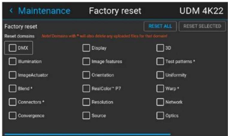
Image 8-92 Example of the reset menu
- Select the checkbox next to the domains that need to be reset and confirm.

Tip: Multiple selections are possible.
- Select RESET SELECTED and confirm.
The selected domains will be reset to their factory settings.
8.9.2 Lens calibration
Location and availability
- Menu: Settings > Maintenance > Lens calibration
- Access level: all
- Models: all
How to calibrate
- In the Maintenance menu, Lens calibration.
Image 8–93 Maintenance menu, lens calibration
The Lens calibration menu is displayed, alongside the status of each
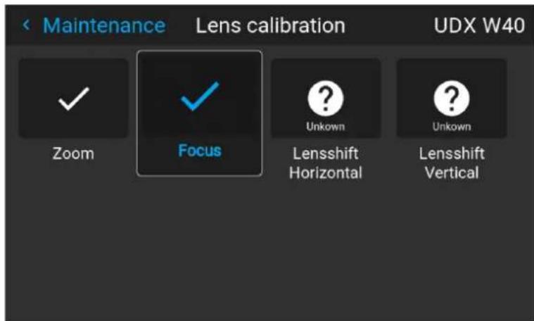
Image 8–94 Example of the lens calibration menu
- Select the desired calibration action and confirm.
Select one of the following calibration functions, depending on the type of mounted lens and projector model:
- Lens shift horizontal
- Lens shift vertical
- Focus
- Zoom
- Illumination Iris
The text Calibrating will be displayed in the icon of the selected function until the calibration is completed.
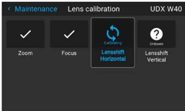
Image 8–95 example of calibration in progress
When an error is detected, the message Calibration Error is displayed next to function.
8.9.3 Flex brightness
Location and availability
- Menu: Settings > Maintenance > FLEX > Brightness
- Access level: all
• Models: QDX, UDX, UDM - Requirements: Flex brightness license

The Flex submenu will only be visible if the projector carries more than one Flex license. If only Flex license is available, choosing the Flex submenu will automatically redirect the user to the Flex Brightness menu.
About Flex Brightness
With the FLEX technology the projector owners can lock the light output to different levels. The locking ca done using one of the following methods:
- Via Projector Toolset when connected to the projector. For more info on how to set up and use the FI licenses, see the Projector Toolset's user guide, chapter “Configuration, License / registration”.
- Via Pulse Prospector, when connected to the projector. For more info on how to set up and use the F licenses, see the Pulse Prospector user guide.
- Via Barco Insights Management Suite when the GSM module is installed. For more information on how set up and use the Flex license, see Insights Management Suite user guide, chapter "Projector Configuration tab" – "Flex brightness"
• Via the OSD menu of the projector itself
To lock to a specific value a 4 digit code is necessary. These codes can be created by the projector or using Pulse Prospector, Projector Toolset or the Insights Management Suite.
Activating Flex brightness
The Flex brightness function is license protected. A Flex license file is linked with the projector type and projector serial number.
The Flex brightness license may be available for purchase. Contact Barco to see if a Flex brightness licer available to purchase for the current projector model.
Once the Flex license has been obtained, upload and activate the license file using Pulse Prospector, Projector Toolset or the Insights Management Suite. For more information about uploading and activating Flex licenses, see the respective user guides.
Flex codes
Once the Flex license is correctly uploaded and activated, the projector creates a number of flex codes, o for each possible maximum light output. These codes are used for rental activities when adapting the light output of the projector.
The created flex codes are only visible in Pulse Prospector, Projector Toolset and the Insights Management Suite by the projector owner. The created Fex codes can be displayed by the projector by uploading the license of the desired projector.
Setting the Flex brightness
- In the Maintenance menu, select Flex > Brightness.
Image 8–96 Flex menu, Flex Brightness
The Flex brightness menu is displayed.
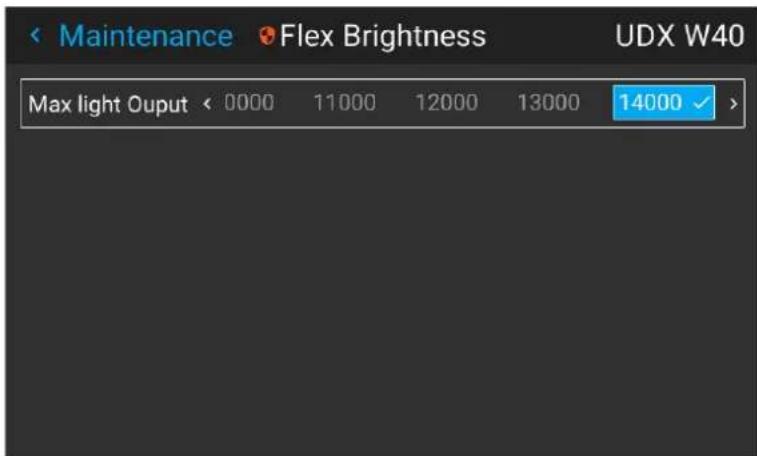
Image 8–97 Example of the Flex brightness menu
- Choose the desired light output for which a code is available.

Tip: All values are listed in lumens.
The pin code entry field will become visible. Once the field is selected, an on-screen keyboard will be prompted.
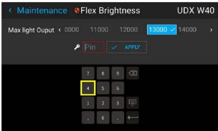
Image 8-98 Example of entering the code in the Flex license menu
- Enter the code and confirm.
- select Apply and confirm
8.9.4 Flex resolution
Location and availability
- Menu: Settings > Maintenance > FLEX > Resolution
- Access level: all
• Models: QDX 4K, UDX 4K, UDM 4K - Requirements: Flex resolution license

The Flex submenu will only be visible if the projector carries more than one Flex license. If only Flex license is available, choosing the Flex submenu will automatically redirect the user to the Flex resolution menu.
Overview
With the FLEX technology the projector owners can lock the resolution to different levels. The locking can done using one of the following methods:
- Via Projector Toolset when connected to the projector. For more info on how to set up and use the FI license, see the Projector Toolset's user guide, chapter “Configuration, License / registration”.
- Via Pulse Prospector, when connected to the projector. For more info on how to set up and use the F licenses, see the Pulse Prospector user guide.
- Via Barco Insights Management Suite when the GSM module is installed. For more information on how set up and use the Flex license, see Insights Management Suite user guide, chapter "Projector Configuration tab" – "Flex resolution"
• Via the OSD menu of the projector itself
To lock to a specific value a 4 digit code is necessary. These codes can be created by the projector or using Pulse Prospector, Projector Toolset or the Insights Management Suite.
Flex codes
Once the flex code is correctly uploaded, the projector creates a number of flex codes, one for each position resolution type:
• 4K-UHD: 3840 x 2400 (default resolution)
• WQXGA: 2560 x 1600 (16:10)
• WUXGA: 1920 x 1200 (16:10)
The created flex codes are only visible in Pulse Prospector, Projector Toolset and the Insights Management Suite by the projector owner. To make these visible he will need his license for this typical projector.
Flex resolution usage
Flex resolution limits the projector output resolution. However, the list of possible input video timings and configurations (EDID) remains unchanged.
The resolution limit is enforced by showing a persistent notification on the projected surface in case an in video timing is chosen (e.g. 4K-UHD on a device with enforced WQXGA resolution).
This way, the user can still see enough content to go through the necessary menus (either to change resolution or update the Flex license), while enough of the screen is blocked for it to be a hindrance for purpose.
Setting the resolution via OSD menu
- In the Maintenance menu, select Flex > Resolution and confirm.
Image 8–99 Flex menu - Resolution
The Flex resolution menu will be displayed.
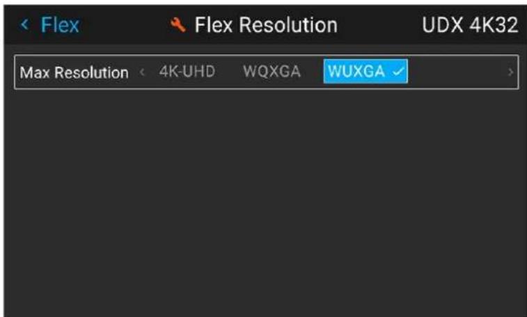
Image 8–100 Example of the Flex resolution menu
- Choose the desired Resolution for which a Flex code is available and confirm.
The pin code entry field will become visible. If the field is selected, an on-screen keyboard will be prompted.
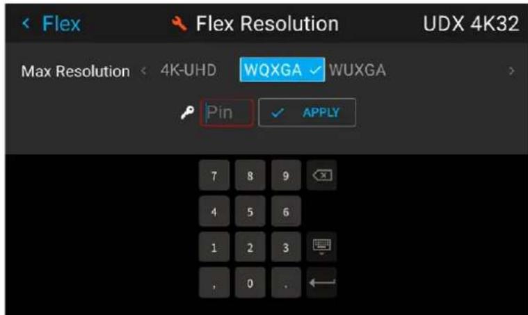
Image 8-101 Example of the Flex Resolution menu with digital keyboard
- Enter the code and confirm.
- Select Apply and confirm.
8.9.5 Rigging frame Calibration
Location and availability
- Menu: Settings > Maintenance > Frame calibration
- Access level: all
• Models: QDX, UDM, UDX, F70 - Requirements: Barco supported motorized rigging frame
How to calibrate the motorized rigging frame
- In the Maintenance menu, select Frame calibration.
Image 8-102 Maintenance menu, Frame calibration
The Frame calibration menu is displayed.
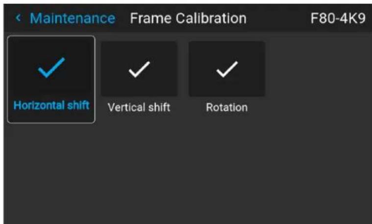
Image 8-103 Example of the Frame calibration menu
- Select the desired calibration action and confirm.
One of the following calibration functions can be chosen:
• Horizontal shift
- Vertical shift
- Rotation
The text Calibrating will be displayed until the calibration is completed.
Image 8-104 Example of a calibration in progress
When an error is detected, the message Calibration Error is displayed next to function.
8.9.6 Electronic convergence
Location and availability
- Menu: Settings > Maintenance > Electronic convergence
- Access level: all
• Models: UDX, UDM, Njord, Hodr
About convergence
Convergence alignment of the red, green and blue can drift due to multiple reasons. There are two ways compensate for this drift:
- Mechanical convergence, must be done by a certified technician.
• Electronic convergence, for quick and minor adjustments by taking pixels out of the total resolution.

Electronic convergence can only be used to align up to two pixels in each direction in increments one pixel. For a more refined convergence method, use the mechanical convergence instead. For more info on the mechanical convergence, consult the service manual of the projector.
About the convergence test pattern
The convergence test pattern consists of horizontal and vertical center lines, as well as two diagonal lines. features three red arrows numbered 1 to 3, and three green arrows numbered 4 to 6. These numbers an colors correspond to the extended control knobs found on the light processor of the projector. The direction each arrow indicates the movement of the channel color (red or green) when turning the corresponding co knob in the direction indicated by the arrow on the knob.
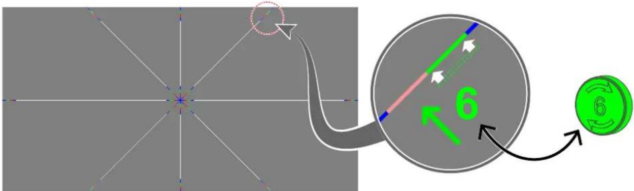
flowchart
graph TD
    A["Start"] --> B{Path}
    B --> C["Circle Component"]
    C --> D["Green Coin Icon with Arrow 6"]
    style A fill:#f9f,stroke:#333
    style D fill:#bbf,stroke:#333
Image 8–105 Convergence test pattern.

Depending on the projector model the convergence test pattern may be slightly different, but the principle remains the same.
How to adjust convergence electronically
-
Project the Convergence test pattern.
-
In the Maintenance menu, select Electronic convergence.
Image 8-106 Maintenance menu, electronic convergence
The Electronic Convergence menu is displayed.
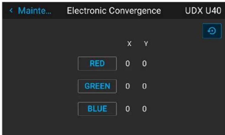
Image 8-107 Example of the electronic convergence menu
- Select the desired X or Y value for one of the three colors and confirm.
- Use the arrow keys to raise or lower the value and confirm.
- Repeat all steps until the desired alignment is achieved.

Press the Reset icon to return all values to the factory settings.
8.10 Advanced settings
About the hidden menu features
There are several menus hidden by default for the standard us. These menus are the following:
• Security (Named "Remote access" in Pulse 2.3 or older)
• Service (Named "Advanced" in Pulse 2.5 or older)
• Diagnostics
These menus will only become visible after logging in as power user, administrator or service technician. For more info on how to log in, see "User rights and logging in", page 23.
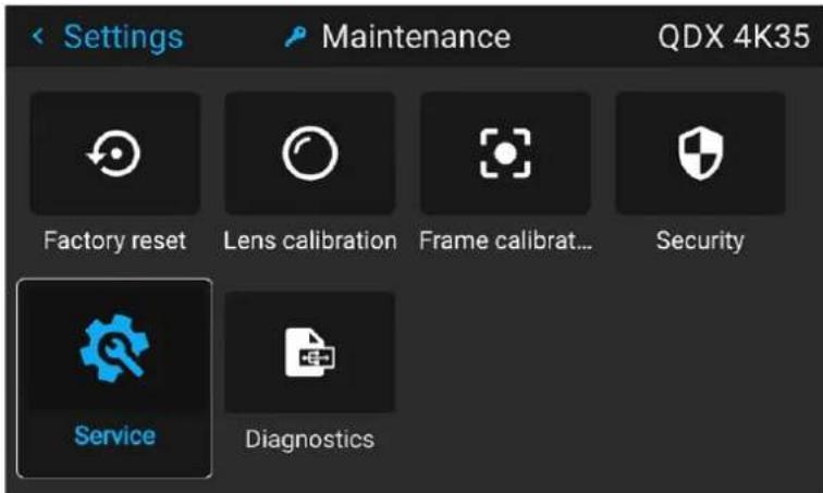
Image 8-108 Example of the Maintenance menu, with the hidden menus unlocked
8.10.1 Security

On Pulse 2.4 and later, the Remote access menu has been renamed to the Security menu. On older versions, please refer to the Remote access menu instead.
8.10.1.1 Security - Enable source preview
Location and availability
- Menu: Settings > Maintenance > Security
- Access level: power user, administrator, service
• Models: QDX, UDM, UDX - Requirements: Distance meter and camera kit
About source preview
This feature is disabled by default for security reasons and has to be enabled manually in both the OSD software and external tools like Pulse Prospector or Projector Toolset.
How to enable source preview
- In the Maintenance menu, select Security.
Image 8-109 Maintenance menu, Security
Settings
The Security menu is displayed.
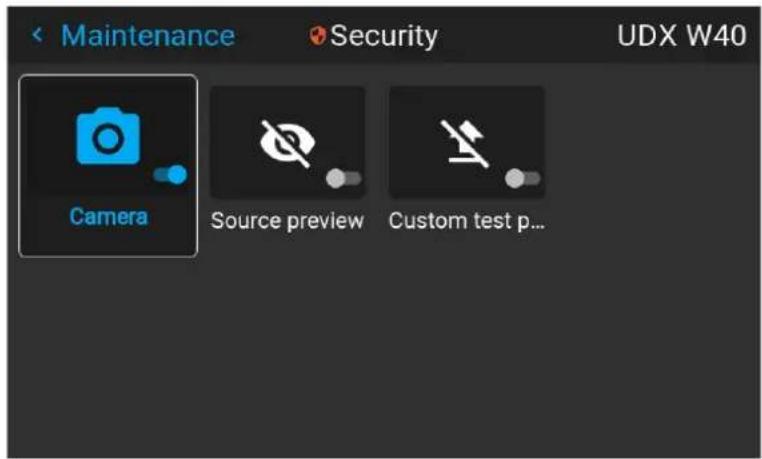
Image 8-110 Example of the Security menu
- Enable the Source preview slider.
Image 8-111 Remote access menu, Source preview is disabled
Image 8-112 Remote access menu, Source preview is enabled
8.10.1.2 Security - Enable camera preview
Location and availability
- Menu: Settings > Maintenance > Security
- Access level: power user, administrator, service
• Models: QDX, UDM, UDX - Requirements: Distance meter and camera kit
About camera preview
When the distance meter and camera kit is installed, the camera should activate. This feature is however disabled by default for security reasons and has to be manually enabled.
How to enable Camera preview
- In the Maintenance menu, select Security.
Image 8-113 Maintenance menu, Security
The Security menu is displayed.
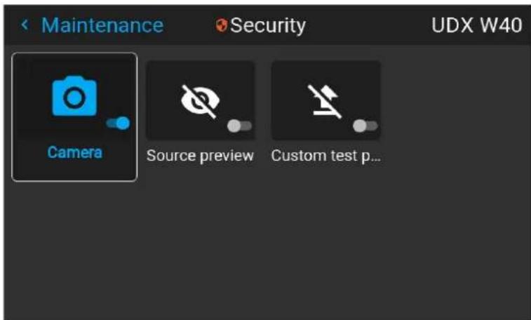
Image 8-114 Example of the Security menu
- Enable the Camera slider.
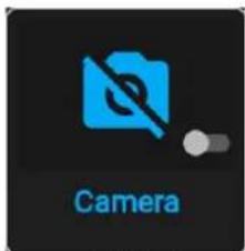
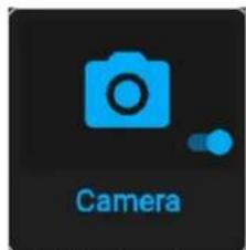
Image 8-115 Security menu, Camera preview is disabled Image 8-116 Security menu, Camera preview is enabled
8.10.1.3 Security - Enable custom test pattern upload
Location and availability
- Menu: Settings > Maintenance > Security
- Access level: power user, administrator, service
- Models: all
- Requirements: Pulse 2.4 or later
About custom test patterns
Up until Pulse 2.4, it has been possible for any user to upload custom test patterns to the projector using external tools like Pulse Prospector or Projector Toolset.
On Pulse 2.4 or later, the ability to upload custom test patterns is disabled by default for security reasons has to be manually enabled in the Pulse OSD software.

Updating the projector from Pulse version 2.3 or older to 2.4 or later will disable Custom test pattern by default. After the update, the feature has to be enabled manually.
How to enable Custom test pattern upload
- In the Maintenance menu, select Security.
Image 8-117 Maintenance menu, Security
The Security menu is displayed.
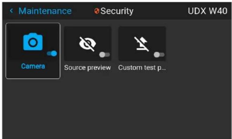
Image 8-118 Example of the Security menu
- Enable the Custom test pattern icon.
Image 8-119 Security menu, Custom test pattern disabled Image 8-120 Security menu, Custom test pattern enabled
8.10.2 Service - RealColor calibration
Location and availability
- Menu: Settings > Maintenance > Service > Native RealColor
- Access level: power user, administrator, service
- Models: all
Location and availability
- Menu: Settings > Maintenance > Service > Factory native RealColor
- Access level: service
- Models: all

CAUTION: The native colors have been measured and set during factory production. Do them, unless parts of the optical path have been replaced due to servicing.
If the native colors on the device must be changed, make sure to also perform a P7 using Pulse Prospector or the Projector Toolset and a chroma meter. For more info on calibration, refer to the Pulse Prospector or Projector Toolset user guide.
not chang
calibration, P7
How to adjust the P7 native settings
- In the Advanced Settings menu, select Native RealColor.
Image 8-121 Advanced Settings, Native Realcolor
The RealColor calibration menu will be displayed.
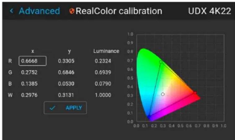
radar
| | x | y | Luminance | | ------ | ----- | ------ | --------- | | R | 0.6668| 0.3305 | 0.2324 | | G | 0.2752| 0.6846 | 0.6939 | | B | 0.1385| 0.0530 | 0.0790 | | W | 0.2976| 0.3131 | 1.0000 |Image 8-122 Example of a RealColor calibration menu
- Select the desired value to change and confirm.
- Change the values to the desired position, taking into account the color gamut values.
- Select APPLY and confirm.
8.10.3 Service - Color wheel
Location and availability
- Menu: Settings > Maintenance > Service > Color wheel
- Access level: power user, administrator, service
• Models: I600, F40, F70, Bragi, Balder
About the Color wheel
Each projector is equipped with one color wheel, which is controlled by the software. The type of used cowheel is determined by the specific projector model purchased. Using the advanced settings menu, a Slider makes it possible to fine-tune the color wheel for variations.
For F70, other color wheels are available upon request. Consult Barco sales office or a service partner in order to find the most suitable color wheel for the specific application.
How to fine-tune the color wheel
- In the Service menu, select Color wheel.
Image 8-123 Advanced Settings, Color wheel
The color wheel menu will be displayed.
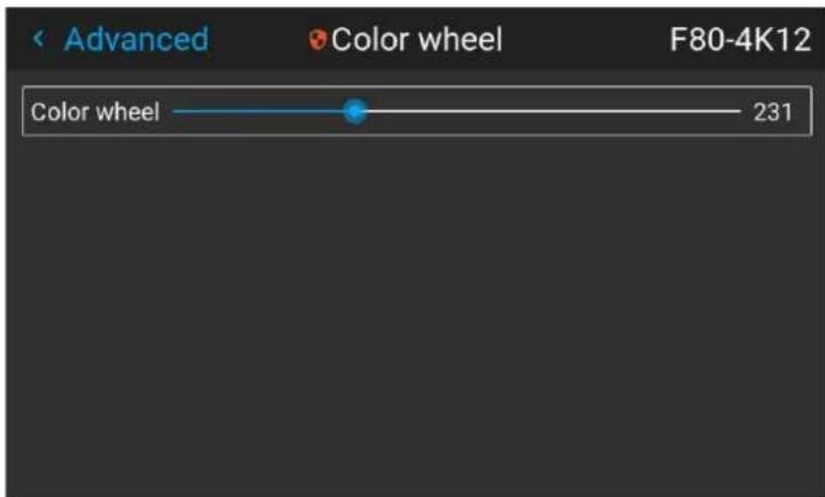
Image 8-124 Example of the Color wheel menu
- Change the slider to the desired position.
8.10.4 Service - Statistics
Location and availability
- Menu: Settings > Maintenance > Service > Statistics
- Access level: power user, administrator, service
- Models: all
What can be seen?
The statistics screen shows general statistical information about the projector and its light source, spread on two tab pages.
The information displayed will vary between projector models.
How to display the statistics
- In the Advanced Settings menu, select Statistics.
Image 8–125 Advanced settings, Statistics
The Statistics menu will be displayed.
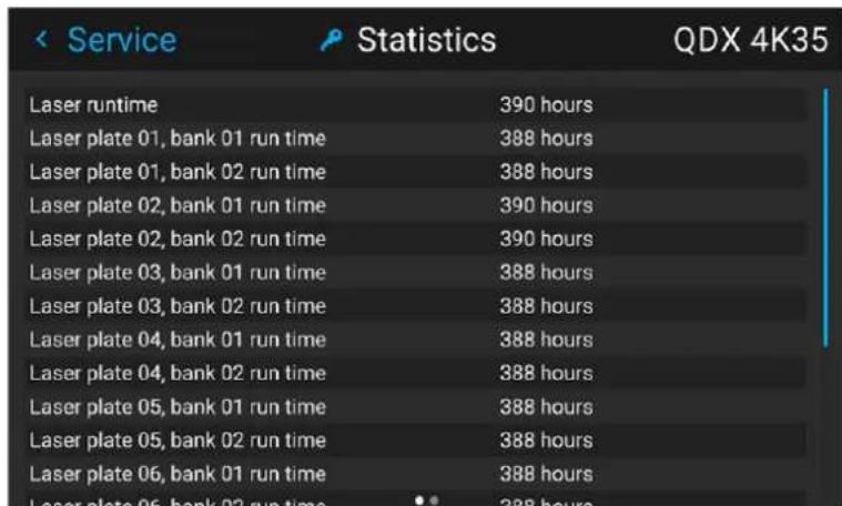
Image 8-126 Example of the Statistics menu
8.10.5 Advanced settings - Laser pulsing calibration
Location and availability
- Menu: Settings > Maintenance > Advanced > Laser pulsing
- Access level: service
• Models: F70, Balder
What is laser pulsing
Laser pulsing is a feature that enables the projector to obtain a specific white y coordinate while keeping the brightness loss to a minimum. As the brightness loss happens in both white and black, this will also keep contrast at the same level. Using RealColor to do the same will result in additional brightness loss and lo contrast.
The projector is tuned to a white y-coordinate of 0.329 for optimal performance but any desired white y-coordinate can be used.
When adjusting the laser pulse value to obtain the desired white y coordinate, the white x coordinate will change accordingly.

Perform a Color calibration once the Laser pulse calibration has been completed.
When to perform laser pulsing calibration
All projectors are calibrated and tested before leaving the factory to ensure build quality and performance of the product. However, when parts of the optical path have been replaced, it is advised to perform a laser pulsing calibration.
Barco recommends to always calibrate the projector within the environment it is to be used. This to compensate for screen type, coating, lens and other environmental factors in a multi-channel set-up. Barco also recommends calibrating both laser pulsing and calibrating native colors at the same time.
Prerequisites
Prepare the projector for laser pulsing as follows:
- Set up the chromameter in front of the projection screen.
- Run the projector and project a white test pattern. Ensure the light source is on for at least 15 minute ensure a stable output.
- Select the Native RealColor preset mode. For more info, see "RealColor P7 - Presets", page 62.
- Select the desired BrilliantColormode. For more info, see "BrilliantColorpage 67
- Select the desired Smear reduction mode. For more info, see "Smear reduction", page 68.
Required tools
Chromameter
How to calibrate
- In the Advanced settings menu, select Laser pulsing.
The Laser pulsing menu is displayed.
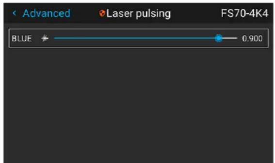
Image 8–127 Example of the Laser pulsing menu
- Change the value of the Laser pulsing slider until the desired y coordinate is achieved
- Navigate to the Native Realcolor menu and input the resulting white x and y coordinates and confirm.
8.10.6 Service - Laser driver calibration
Location and availability
- Menu: Settings > Maintenance > Service > Laser driver calibration
- Access level: service
- Models: QDX
When to perform laser driver calibration
All projectors are calibrated and tested before leaving the factory to ensure build quality and performance of the product. However, when parts of the light source or the LDM has been replaced, it is advised to perform laser driver calibration. This to ensure a proper link between laser driver boards of the LDM and the laser plates of the light source.
Barco recommends to always calibrate the projector within the environment it is to be used. This to compensate for screen type, coating, lens and other environmental factors in a multi-channel set-up.
How to perform a laser driver calibration
- Make sure the projector is in Ready mode.
- In the Service menu, click Laser driver calibration.
Image 8–128 Service menu, Laser driver calibration
- Confirm the action.
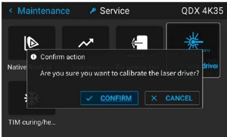
Image 8-129 Example of the laser driver confirmation dialog
The Laser driver calibration will commence. In case of failure, notifications may be triggered. In case of success, the timestamp will be marked in the Laser driver calibration icon.
8.10.7 Service - Pixel shift
Location and availability
- Menu: Settings > Maintenance > Service > Pixel shift
- Access level: service
• Models: I600, F400, FL40 4K, FS40 4K, F70 4K, Bragi, Balder
About pixel shift
4K projector models use an actuator to achieve a 4K resolution. If a new actuator or lens holder (contain actuator) is installed on the projector, it is advised to update this menu with the new information.
The new actuator can be calibrated by using the XPR test pattern and subsequently adjusting parameters the Pixel shift menu until the desired result is achieved.
The settings depend on the generation type of actuator.
- For Generation I actuators (FL40, FS40, F70, Bragi, Balder):
- Gain: The amplitude of the waveform, sent to the actuator. Default value: 0.65
- Resonance: The frequency of the actuator. When this value is 0, the actuator is off. High frequencies mean much noise. Default value: 227 Hz
- For Generation II actuators (F400, I600):
- V gain: The amplitude of the vertical waveform, sent to the actuator.
- H gain: The amplitude of the horizontal waveform, sent to the actuator.
How to fine-tune the actuator
- Make sure the projector orientation is set to Desktop front. For more info, refer to "Orientation", page 74.

Tip: For the best possible result, it is advised to only use the desktop front orientation while performing pixel shift, no matter how the projector is actually mounted.
- In the Advanced Settings menu, select Pixel Shift.
Image 8–130 Advanced settings, Pixel shift
The Pixel Shift menu will be displayed. Also, the the XPR test pattern (Cross hatch) will be projected.
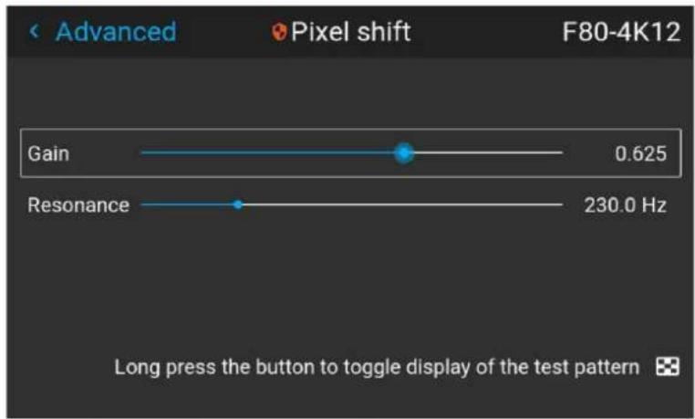
bar
| Metric | Value | | ---------- | ------- | | Gain | 0.625 | | Resonance | 230.0 Hz |Image 8-131 Example of the pixel shift menu on Gen I actuators
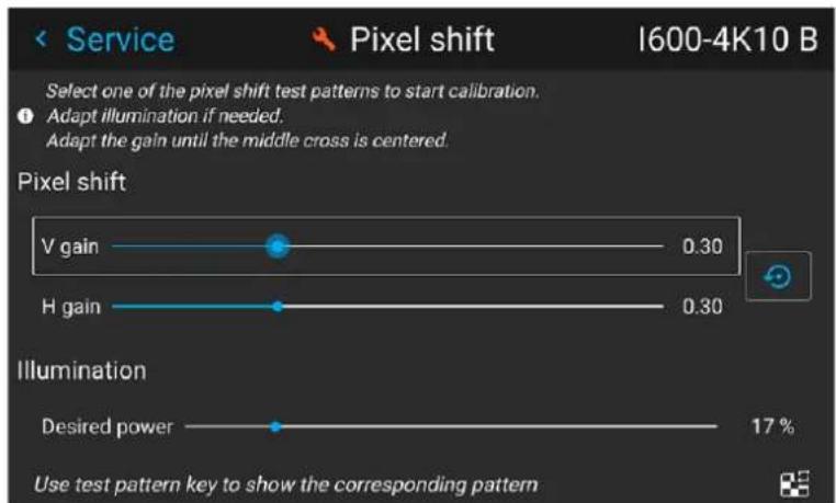
Image 8-132 Example of the pixel shift menu on Gen II actuators
- Use the Gain and/or Resonance sliders to fine tune the actuator until the center marker hits the bull's-eye. Use Align both following images with the sliders available in this menu.
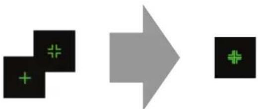
flowchart
graph LR
    A["Black Square with + and #"] --> B["Gray Arrow"]
Image 8-133 The alternating XPR test pattern
8.10.8 Advanced settings - Optical filter
Location and availability
- Menu: Settings > Maintenance > Advanced > Optical filter
- Access level: Power user, administrator, service
• Models: F70, Balder
How to
- In the Advanced settings menu, select Optical Filter.
Image 8-134 Advanced menu, Optical filter
The Optical filter menu will be displayed.
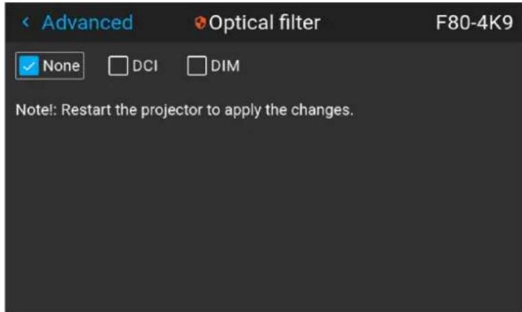
Image 8-135 Example of the Optical filter menu
- Select the desired Optical filter setting(s).
- Restart the projector to apply the changes
8.10.9 Service - Status of the laser banks
Location and availability
- Menu: Settings > Maintenance > Service > Laser banks
- Access level: Power user, administrator, service
• Models: UDM, UDX, Njord, Hodr
About failing laser banks
The projector is powered by a laser light source, which has multiple laser banks. The light output and col performance is dependant on the number of active laser banks.
If one or more laser banks have failed of a certain type, a decreased light input and decrease in color performance might be visible. But the projector will keep on playing, unless too many banks of a certain will have failed.

In order to disable a certain laser bank, or calibrate the projector after disabling one or more laser banks, please refer to the Pulse Prospector or Projector Toolset user guide.
How to check the status of the Laser Banks
- In the Advanced settings menu, select Laser Banks.
Image 8-136 Advanced menu, Laser banks
The Laser group statistics menu is displayed.
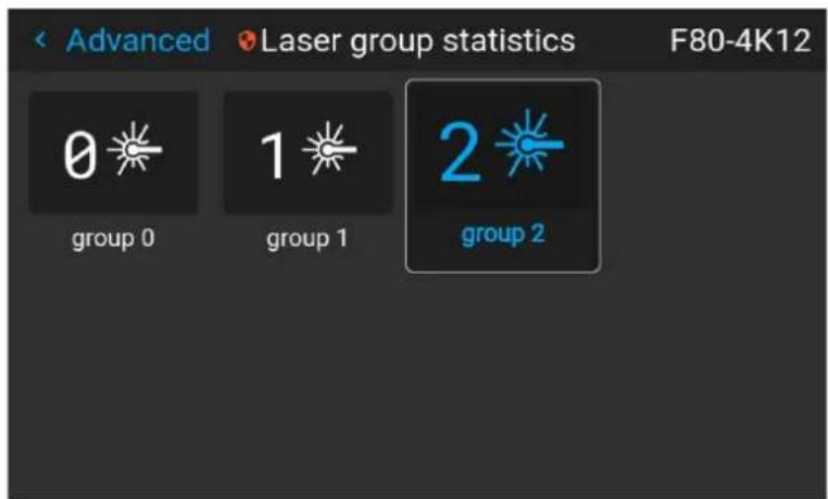
Image 8–137 Example of the Laser group statistics menu
- Select the desired laser group.
The laser banks group page will be displayed, showing which banks are operational and which have failed.
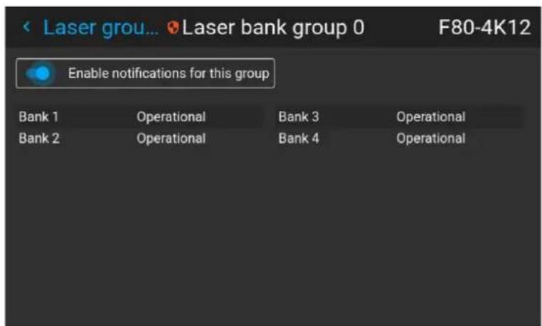
Image 8-138 Example of the laser bank group menu
- Enable or disable the Enable notifications for this group slider.
8.10.10 Service - Tilt sensor calibration
Location and availability
- Menu: Settings > Maintenance > Service > Tilt sensor calibration
- Access level: Power user, administrator, service
- Models: all
About the tilt sensor calibration
If the tilt sensor isn't working correctly, the tilt sensor calibration feature can be used to calibrate the tilt sensor.

CAUTION: The calibration procedure resets the values of the tilt sensor to 0 in the current position of the projector. For the optimal working of the tilt sensor it is important to make sure perfectly level when performing this procedure. If not, the tilt sensor will not function as the calibration has been completed.
the project desired or
Required tools
Level
How to calibrate the tilt sensor?
- Place the projector on a flat surface and make sure it is positioned level in all directions. Use a level tool to help ensure this.
- In the Advanced settings menu, select Tilt sensor calibration.
Image 8–139 Advanced menu, Tilt sensor calibration
- Confirm the action.
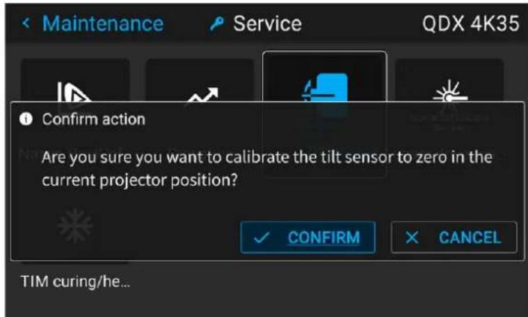
Image 8-140 Example of the Advanced menu with the Tilt sensor menu
The tilt sensor will be set to zero in the current position of the projector.
8.10.11 Service - TIM curing/heating
Location and availability
- Menu: Settings > Maintenance > Service > TIM curing
- Access level: service
• Models: QDX, UDM, F40, F400, Bragi, Njord, Hodr

For F40 and Bragi, the TIM curing will only be available from Pulse 2.5 and later.
About TIM curing
The TIM curing process is only used during service action on the DMDs and/or laser plates.
For more information on when to us TIM curing or laser curing (if available), see the service manual of the projector.
How to activate a TIM curing process
- In the Service menu, select TIM curing/Tim heating.
Image 8-141 Advanced menu, TIM Curing
The TIM curing/TIM heating menu is displayed.
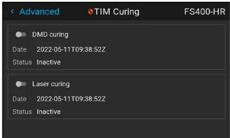
Image 8-142
- To activate DMD curing, enable the DMD curing slider confirm.
- To activate Laser curing, enable the Laser curing slider and confirm.
8.10.12 Creating a diagnostics package using the OSD
Location and availability
- Menu: Settings > Maintenance > Diagnostics
- Access level: Power user, administrator, service
- Models: all
- Requirements: Pulse 2.4 or later
What can be done?
Up until Pulse 2.4, in order to obtain the diagnostics package of the projector, an external tool like the Projector Toolset was required, or a custom "log extractor" file that was version specific.
On Pulse 2.4 and later, the diagnostics package can be downloaded directly from the projector itself onto USB flash drive.
Specifications USB flash drive
The USB flash drive needs to be:
- USB 2.0
- Formatted in FAT32
• Have enough free space for the package
How to download a diagnostics package
-
Enter a valid USB flash drive into the USB 2.0 slot on the communication panel of the projector.
-
In the Maintenance menu, select Diagnostics.
Image 8-143 Maintenance menu, Diagnostics
The Diagnostics menu will be displayed.
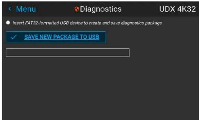
Image 8-144 Example of the Dianostics menu, with a valid USB flash drive inserted.
- Click the Save new package to USB button.

Note: If no (valid) USB flash drive is inserted, the Save new package to USB button will be disabled.
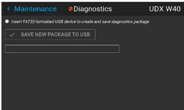
Image 8-145 Example of the Diagnostics menu with no valid USB flash drive inserted.
The Diagnostics package creation process will start. A package will first be prepared, then created and then saved onto the flash drive.
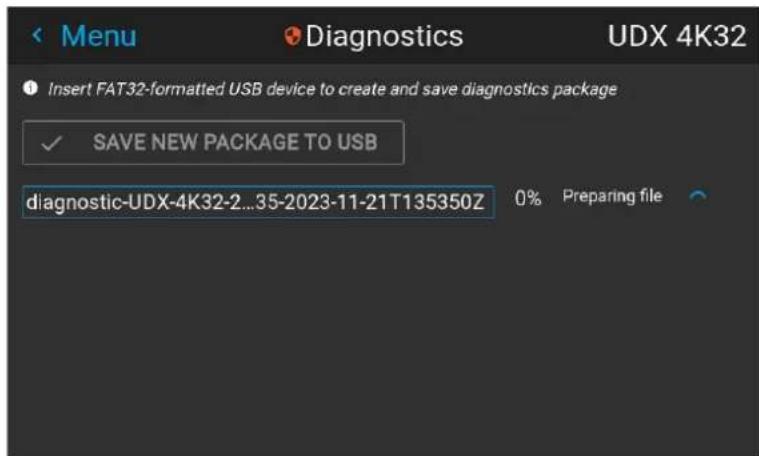
Image 8–146 Example of the creation of a diagnostics package
Note: Take into account that this process will take about 5 to 10 minutes.
- Once the package creation process completed, a notification will be prompted that it is now safe to remove the USB device.
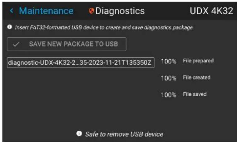
Image 8-147 Example of a completed diagnostics package creation
8.11 General
8.11.1 List of open source licenses
Location and availability
- Menu: Settings > General > Open source licences
- Access level: all
- Models: all
About open source licenses
Open source licenses are licenses that comply with the Open Source Definition. In brief, they allow software be freely used, modified, and shared.
To be open and transparent about the open source software used on the projector, a list of all open sources licenses used is available in the software.
How to find the open source licenses
For the complete and most up-to-date list of the used open source software and the version used, go to main menu and select Settings > General >> Open source licenses.
Image 8–148 General menu – Open source licenses
8.11.2 End-user license agreement (EULA)
Location and availability
- Menu: Settings > General > End User License Agreement
- Access level: all
- Models: all
- Requirements: Pulse 2.4 or later
About the EULA
Upon first startup of the projector, the user will be asked to accept the end-user license agreement (EULA before being able to use all functionality of the projector.

On simulation projectors (FL40, FS40, F70, F400), the EULA approval process happens during the purchasing process instead.
After accepting the EULA, the text of the EULA can still be consulted.

There is no option to re-accept or reject the EULA. It is only available for consulting purposes.
How to find the EULA after accepting it
In the General menu, select End User Licence Agreement.
Image 8-149 General menu - EULA
Test patterns
9
9.1 Test Patterns
Location and availability
- Menu: Test Patterns
- Access level: all
- Models: all

The Test patterns menu will only be accessible when the light source is on.
List of standard test patterns
The test patterns that are available by default are the following:
- Aspect
- Focus-Green
- Focus-bursts
- White / Black/ Red / Green / Blue
• Cyan / Magenta / Yellow - Color bars
• Color gradients - Checkerboard
- Cross hatch
- Geometry
• Horizontal gray bars
• Vertical gray bars - 3D Stereo
About the test pattern types
There are three types of test patterns possible in the projector:
| Type Explanation | Example of test pattern icon | |
| Standard test patterns | One of the standard test patterns listed before. |  |
| Warped test patterns | Every test pattern will have a “warped” variant available, symb with a “warp” symbol on the top-left corner of the icon.If warping is enabled and configured, the warping will be app this test pattern. If warping is disabled or not configured, a v test pattern will be identical to its standard test pattern varianRequirement: Pulse 2.2 or later | 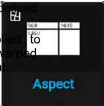 |
| Custom test patterns | Can be uploaded via an external tool. Custom test patterns a warped variants can be found at the bottom of the list of av patterns.All standard test patterns will have a unique icon. Custom up test patterns on the other end will be marked with a “default pattern file” icon. |  |
How to use test patterns
-
In the Test pattern menu, select the desired test pattern from the list.
-
To turn the test pattern off, select off instead.
Image 9-1 Test patterns menu, test pattern off
Shortcut buttons
On the keypad or remote, press the test patterns button (☑). When either of these buttons is pressed, a popup menu will be prompted on the LCD screen and OSD, showing a horizontal list of the available test patterns.
When prompted, use the arrow keys and select the desired test pattern. Confirm with the OK button.
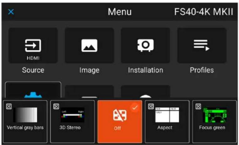
Image 9-2 Test pattern pop up menu
Dashboard
10
10.1 Dashboard overview 226

From Pulse 2.5 onward, the Status menu has been renamed into the Dashboard menu. While the name has changed, the functionality remains the same.
For older software versions, refer to the Status menu instead.
10.1 Dashboard overview
Location and availability
- Menu: Dashboard
- Access level: al
- Models: all

In Pulse 2.5 and later, the Status menu has been renamed to Dashboard. On Pulse 2.4 or older, refer to the Status menu instead.
How to access the Dashboard menu
While in the main menu, press Dashboard.
Image 10-1 Main menu, Dashboard
The Dashboard menu is displayed.
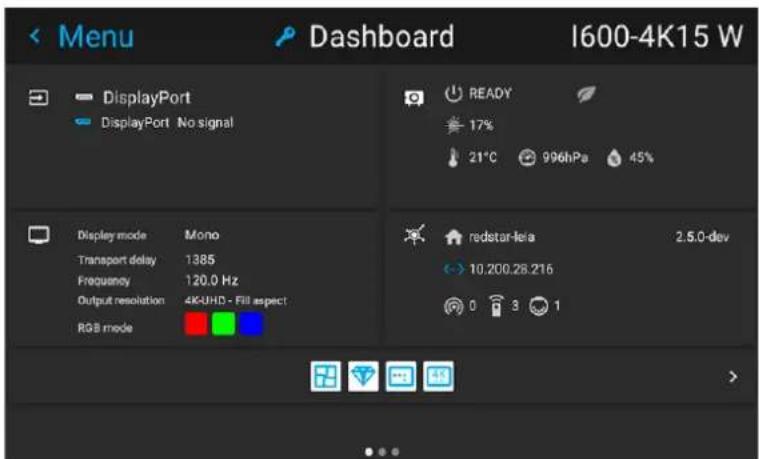
Image 10-2 Example of the Dashboard menu
Swipe the screen left of right to swap between the three different pages.
Features on the first dashboard page
- Connected source and signal details
- Display settings (e.g. display mode, transport delay, output resolution, etc)
- Projector power and environmental details (e.g. power, temperature, pressure, etc)
• Network status (e.g. host name, IP address, software version)
Features on the second dashboard page (Functions)
From Pulse 2.5 and later, the Functions page has been added to the dashboard.
The Functions page is the list of all available functions as icons. Inactive functions are greyed out, whereas active functions are lit white.
Use the arrow keys to navigate through all functions. Pressing one of the functions will redirect the user to respective menu (shortcut).

Pressing the return button on the respective menu afterwards will also redirect the user Functions page.
back to tr
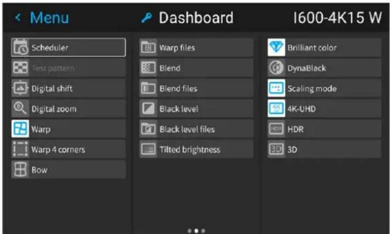
Image 10-3 Example of the Functions page of the Dashboard
Features on the third dashboard page (About)
- Projector information, e.g. firmware version, serial number, projector article number and registration status (if applicable).
- Mounted lens: lens type and lens description (if available).
- Basic projector statistics: Light source/illumination status, uptime, runtime, system runtime
- Licensed features : Information on licenses (e.g. Flex Resolution, Flex Brightness)
• Time and Schedule: Active time zone, current date and time, first upcoming scheduled event.
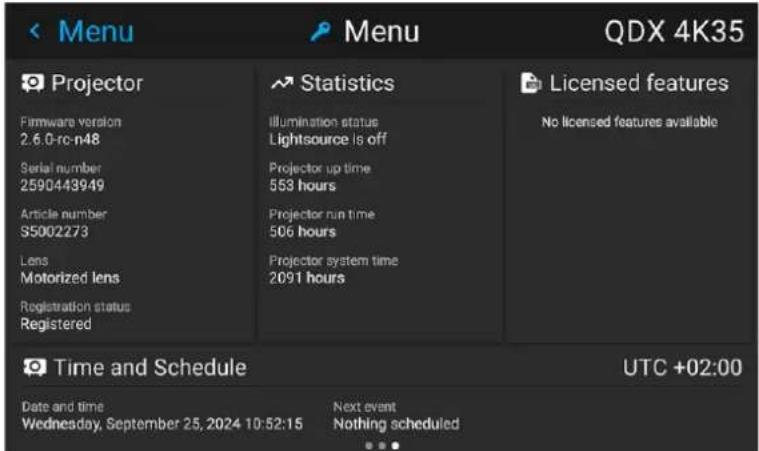
Image 10-4 Example of the About page of the Dashboard
DMX charts
A
A.1 DMX chart input module position....230
A.2 DMX charts, Basic 231
A.3 DMX chart, Extended 234
A.1 DMX chart input module position
About the input boards
The projectors have a Control and Communication panel, as well as up to two input slots (amount dependent model). These input slots are marked internally as "L1" and "L2".
The input selection commands in the basic DMX chart only applies to the input module in slot L1.
The input selection commands in the extended DMX chart are as follows:
- Use channel 2 to target the input module located in slot L1
- Use channel 14 to target the input module located in slot L2 (if available).
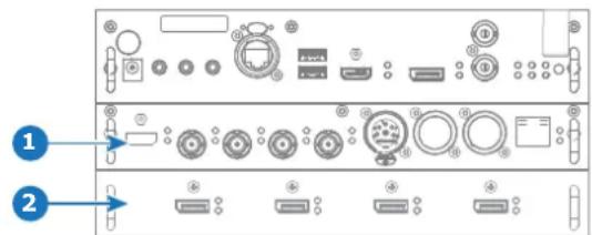
Image A-1
1 Slot L1, here filled with the Quad combo Input MKIII module
2 Slot L2, here filled with the Quad DP 1.2 Input module
A.2 DMX charts, Basic
Chart for QDX and I600
| Ch. | Function Value | Default Action | ||
| 1 | Shutter + Intensity | 0 - 7 255 | Close shutterAdjust intensity | |
| 8 - 255 | ||||
| 2 | Profile selection + Input selection on input board installed in slot L | 0 - 7 0 | No functionActivate firstActivate secondActivate thirdActivate fourthActivate fifthActivate sixthActivate seventhActivate eighthActivate ninthActivate tenthSelect HDM | profile preset (If held for 1 second) |
| 8 - 15 | ||||
| 16 - 23 | nd profile preset (If held for 1 second) | |||
| 24 - 31 | profile preset (If held for 1 second) | |||
| 32 - 39 | th profile preset (If held for 1 second) | |||
| 40 - 47 | profile preset (If held for 1 second) | |||
| 48 - 55 | profile preset (If held for 1 second) | |||
| 56 - 63 | enth profile preset (If held for 1 second) | |||
| 64 - 71 | th profile preset (If held for 1 second) | |||
| 72 - 79 | profile preset (If held for 1 second) | |||
| 80 - 87 | profile preset (If held for 1 second) | |||
| 88 - 95 | input on the Control and Communication module (If held for 1 second) | |||
| 96 - 103 | Select DisplayPort input on the Control and Communication module (If held for 1 second) | |||
| 104 - 111 | Select HDMI input on Quad Combo MKIII (If held for 1 second) | |||
| 112 - 119 | Select SDI Input A on Quad Combo MKIII (If held for 1 second) | |||
| 120 - 127 | Select SDI Input B on Quad Combo MKIII (If held for 1 second) | |||
| 128 - 135 | Select SDI Input C on Quad Combo MKIII (If held for 1 second) | |||
| 136 - 143 | Select SDI Input D on Quad Combo MKIII (If held for 1 second) | |||
| 144 - 151 | Select Quad SDI on Quad Combo MKIII (If held for 1 second) | |||
| 152 - 159 | Select HDBaseT input on Quad Combo MKIII installed in slot L1 (If held for 1 second) | |||
| 160 - 167 | Select DisplayPort Input A on Quad DP if installed in slot L1 (If held for 1 second) | |||
| 168 - 175 | Select DisplayPort Input B on Quad DP if installed in slot L1 (If held for 1 second) | |||
| 176 - 183 | Select DisplayPort Input C on Quad DP if installed in slot L1 (If held for 1 second) | |||
| 184 - 191 | Select DisplayPort Input D on Quad DP if installed in slot L1 (If held for 1 second) | |||
| 192 - 199 | Select Dual DisplayPort AB on Quad DP if installed in slot L1 (If held for 1 second) | |||
| 200 - 207 | Select Quad column DisplayPort on Quad DP installed in slot L1 (If held for 1 second) | |||
| 208 - 215 | Power on Power down Reserved for future functionality | / Light source on (If held for 5 seconds) | ||
| 216 - 223 | n / Light source off (if held for 5 seconds) | |||
| 224 - 255 |
Chart for UDX, UDM, Njord and Hodr
| Ch. | Function Value | Default Action | ||
| 1 | Shutter + Intensity | 0 - 7 255 | Close sh | utter |
| 8 - 255 | Adjust intensity | |||
| 2 | Function select | 0 - 7 | 0 No | function |
| 8 - 15 | Activate first profile preset (If held for 1 second) | |||
| 16 - 23 | Activate second profile preset (If held for 1 second) | |||
| 24 - 31 | Activate third profile preset (If held for 1 second) | |||
| 32 - 39 | Activate fourth profile preset (If held for 1 second) | |||
| 40 - 47 | Activate fifth profile preset (If held for 1 second) | |||
| 48 - 55 | Activate sixth profile preset (If held for 1 second) | |||
| 56 - 63 | Activate seventh profile preset (If held for 1 second) | |||
| 64 - 71 | Activate eighth profile preset (If held for 1 second) | |||
| 72 - 79 | Activate ninth profile preset (If held for 1 second) | |||
| 80 - 87 | Activate tenth profile preset (If held for 1 second) | |||
| 88 - 95 | Select input 1: HDMI Input (If held for ^12 second) | |||
| 96 - 103 | Select input 2: DisplayPort Input (If held for 1 second) | |||
| 104 - 111 | Select input 3: SDI Input A (If held for 1 second) ^12 | |||
| 112 - 119 | Select input 4: SDI Input B (If held for 1 second) ^12 | |||
| 120 - 127 | Select input _12 | 5: HDBaseT Input 1 (if held for 1 second) | ||
| 128 - 135 | Select input | 6: Quad SDI input (if held for 1 second) ^12 | ||
| 136 - 143 | Select input | 7: Quad DP board Input A (if held for 1 second) ^13 | ||
| 144 - 151 | Select input | 8: Quad DP board Input B (if held for 1 second) ^13 | ||
| 152 - 159 | Select input | 9: Quad DP board Input C (if held for 1 second) ^13 | ||
| 160 - 167 | Select input | 10: Quad DP board Input D (if held for 1 second) ^13 | ||
| 168 - 175 | Select input | 11: Quad DP board Inputs A-B (if held for 1 second) ^13 | ||
| 176 - 183 | Select input | 12: Quad DP board quad column mode (if held for 1 second) | ||
| 184 - 207 | Reserved for future functionality | |||
| 208 - 215 | Power on / Light source on (If held for 5 seconds) | |||
| 216 - 223 | Power down / Light source off (if held for 5 seconds) | |||
- Only when the Quad Combo input board is installed in slot L1
- Only when the Quad DisplayPort input board is installed in slot L2
| Ch. | Function Value | Default Action | ||
| 224 - 255 | Reserved for future functionality | |||
A.3 DMX chart, Extended
Overview for QDX and 1600
| Ch. | Function Value | Default Actions | ||
| 1 | Shutter + Intensity | 0 - 7 255 | Close shutter | |
| 8 - 255 | Adjust intensity | |||
| 2 | Brightness 0 - 255 | 128 Adjusts | the brightness between 0 and 100% on input. | |
| 3 | Contrast | 0 - 255 128 Adjusts the contrast between 0 and 100% on input | ||
| 4 | Profile selection + Input selection on input board installed in slot L1 | 0 - 7 | 0 No function | |
| 8 - 15 | Activate second | Activate first profile preset (If held for 1 second) | ||
| 16 - 23 | Activate third | nd profile preset (If held for 1 second) | ||
| 24 - 31 | Activate fourth | profile preset (If held for 1 second) | ||
| 32 - 39 | Activate fifth | th profile preset (If held for 1 second) | ||
| 40 - 47 | Activate sixth | profile preset (If held for 1 second) | ||
| 48 - 55 | Activate seventh | profile preset (If held for 1 second) | ||
| 56 - 63 | Activate eighth | nth profile preset (If held for 1 second) | ||
| 64 - 71 | Activate eighth | th profile preset (If held for 1 second) | ||
| 72 - 79 | Activate ninth | profile preset (If held for 1 second) | ||
| 80 - 87 | Activate tenth | profile preset (If held for 1 second) | ||
| 88 - 95 | Select HDM | input on the Control and Communication module (If held for 1 second) | ||
| 96 - 103 | Select DisplayPort input on the Control and Communication module (If held for 1 second) | |||
| 104 - 111 | Select HDMI input on Quad Combo MKIII if installed in slot L1 (If held for 1 second) | |||
| 112 - 119 | Select SDI Input A on Quad Combo MKIII if installed in slot L1 (If held for 1 second) | |||
| 120 - 127 | Select SDI Input B on Quad Combo MKIII if installed in slot L1 (If held for 1 second) | |||
| 128 - 135 | Select SDI Input C on Quad Combo MKIII if installed in slot L1 (If held for 1 second) | |||
| 136 - 143 | Select SDI Input D on Quad Combo MKIII if installed in slot L1 (If held for 1 second) | |||
| 144 - 151 | Select Quad SDI on Quad Combo MKIII if installed in slot L1 (If held for 1 second) | |||
| 152 - 159 | Select HDBaseT input on Quad Combo MKIII installed in slot L1 (If held for 1 second) | |||
| 160 - 167 | Select DisplayPort Input A on Quad DP if installed in slot L1 (If held for 1 second) | |||
| 168 - 175 | Select DisplayPort Input B on Quad DP if installed in slot L1 (If held for 1 second) | |||
| 176 - 183 | Select DisplayPort Input C on Quad DP if installed in slot L1 (If held for 1 second) | |||
| 184 - 191 | Select DisplayPort Input D on Quad DP if installed in slot L1 (If held for 1 second) | |||
| 192 - 199 | Select Dual DisplayPort AB on Quad DP if installed in slot L1 (If held for 1 second) | |||
| 200 - 207 | Select Quad | d column DisplayPort on Quad DP if installed in slot L1 (If held for 1 second) | ||
| 208 - 215 | Select Quad | d DisplayPort on Quad DP if installed in slot L1 (If held for 1 second) | ||
| 216 - 223 | Select Fiber | input A if Pulse SFP is installed in slot L1 | ||
| 224 - 231 | Select Fiber | input B if Pulse SFP is installed in slot L1 | ||
| 232 - 255 | Reserved for future functionality | |||
| 5 | Focus (MSB) 0 - 255 | 128 Set | coarse lens focus adjustment ^14 | |
| 6 | Focus (LSB) 0 - 255 | 128 Set | fine lens focus adjustment ^14 | |
| 7 | Zoom (MSB) 0 - 255 | 128 Set | coarse lens zoom adjustment ^14 | |
| 8 | Zoom (LSB) 0 - 255 | 128 Set | fine lens zoom adjustment ^14 | |
| 9 | Lens shift vertical (MSB) | 0 - 255 | 128 Set coarse lens shift in vertical direction | |
| 10 | Lens shift vertical (LSB) | 0 - 255 | 128 Set fine lens shift in vertical direction | |
| 11 | Lens shift horizontal (MSB) | 0 - 255 | 128 Set coarse lens shift in horizontal direction | |
| 12 | Lens shift horizontal (LSB) | 0 - 255 | 128 Set fine lens shift in horizontal direction | |
| 13 | Light Source Power ^15 | 0 | 0 Set light source to 100% | |
| 1 - 61 | ||||
| 64 | ||||
| 67 | ||||
| 70 | ||||
| 73 | ||||
| 76 | ||||
| 79 | ||||
| 80 - 87 | ||||
| 88-95 | ||||
| 96 - 255 | ||||
| 14 | Calibration + Input selection on input board installed in slot L2 (if available) | 0 - 7 | 0 No functionality | |
| 8 - 15 | ||||
| 16 - 23 | ||||
| 24 - 31 | ||||
| 32 - 103 | ||||
| 104 - 111 | ||||
| 112 - 119 | ||||
- Only when lens has been calibrated
- If the Light Source is forced to an output below its minimum value, it will remain at its minimum output value
| Ch. | Function Value | Default Actions | ||
| 120 - 127 | Select SDI | Input B on Quad Combo MKIII if installed in slot L2 (If held for 1 second) | ||
| 128 - 135 | Select SDI | Input C on Quad Combo MKIII if installed in slot L2 (If held for 1 second) | ||
| 136 - 143 | Select SDI | Input D on Quad Combo MKIII if installed in slot L2 (If held for 1 second) | ||
| 144 - 151 | Select Quad | SDI on Quad Combo MKIII if installed in slot L2 (If held for 1 second) | ||
| 152 - 159 | Select HDB | BaseT input on Quad Combo MKIII if installed in slot L2 (If held for 1 second) | ||
| 160 - 167 | Select Display | PlayPort Input A on Quad DP if installed in slot L2 (If held for 1 second) | ||
| 168 - 175 | Select Display | PlayPort Input B on Quad DP if installed in slot L2 (If held for 1 second) | ||
| 176 - 183 | Select Display | PlayPort Input C on Quad DP if installed in slot L2 (If held for 1 second) | ||
| 184 - 191 | Select Display | PlayPort Input D on Quad DP if installed in slot L2 (If held for 1 second) | ||
| 192 - 199 | Select Dual | DisplayPort AB on Quad DP if installed in slot L2 (If held for 1 second) | ||
| 200 - 207 | Select Quad | d column DisplayPort on Quad DP if installed in slot L2 (If held for 1 second) | ||
| 208 - 215 | Select Quad | d DisplayPort on Quad DP if installed in slot L2 (If held for 1 second) | ||
| 216 - 223 | Select Fiber | input A if Pulse SFP is installed in slot L2 | ||
| 224 - 231 | Select Fiber | input B if Pulse SFP is installed in slot L2 | ||
| 232 - 255 | Reserved for future functionality | |||
Overview on UDX, UDM, F400, Njord and Hodr
| Ch. | Function Value Default Actions | |||
| 1 | Shutter + Intensity | 0 - 7 | 255 | Close shutter |
| 8 - 255 | Adjust intensity | |||
| 2 | Brightness | 0 - 255 | 128 | Adjusts the brightness between 0 and 100% on input. |
| 3 | Contrast | 0 - 255 | 128 | Adjusts the contrast between 0 and 100% on input |
| 4 | Input selection | 0 - 7 | 0 No function | |
| 8 - 15 | ||||
| 16 - 23 | ||||
| 24 - 31 | ||||
| 32 - 39 | ||||
| 40 - 47 | ||||
| 48 - 55 | ||||
| 56 - 63 | ||||
| 64 - 71 | ||||
| 72 - 79 | ||||
| 80 - 87 | ||||
| Ch. | Function Value | Default Actions | ||
| 88 - 95 | Select input | 1: HDMI Input (If held for 1 second) ^12 | ||
| 96 - 103 | Select input | _12^2 : DisplayPort Input (If held for 1 second) | ||
| 104 - 111 | Select input | 3: SDI Input A (If held for 1 second) ^12 | ||
| 112 - 119 | Select input | 4: SDI Input B (If held for 1 second) ^12 | ||
| 120 - 127 | Select input | _12^5 : HDBaseT Input 1 (if held for 1 second) | ||
| 128 - 135 | Select input | 6: Quad SDI input (if held for 1 second) ^12 | ||
| 136 - 143 | Select input | 7: Quad DP board Input A (if held for 1 second) ^13 | ||
| 144 - 151 | Select input | 8: Quad DP board Input B (if held for 1 second) ^13 | ||
| 152 - 159 | Select input | 9: Quad DP board Input C (if held for 1 second) ^13 | ||
| 160 - 167 | Select input | 10: Quad DP board Input D (if held for 1 second) ^13 | ||
| 168 - 175 | Select input | 11: Quad DP board Inputs A-B (if held for 1 second) ^13 | ||
| 176 - 183 | Select input | 12: Quad DP board quad column mode (if held for 1 second) | ||
| 184 - 255 | Reserved for future functionality | |||
| 5 | Focus (MSB) 0 - 255 | 128 | Set coarse | lens focus adjustment ^16 |
| 6 | Focus (LSB) | 0 - 255 | 128 Set | fine lens focus adjustment ^14 |
| 7 | Zoom (MSB) | 0 - 255 | 128 Set | coarse lens zoom adjustment ^14 |
| 8 | Zoom (LSB) | 0 - 255 | 128 Set | fine lens zoom adjustment ^14 |
| 9 | Lens shift vertical (MSB) | 0 - 255 | 128 Set | coarse lens shift in vertical direction |
| 10 | Lens shift vertical (LSB) | 0 - 255 | 128 Set | fine lens shift in vertical direction |
| 11 | Lens shift horizontal (MSB) | 0 - 255 | 128 Set | coarse lens shift in horizontal direction |
| 12 | Lens shift horizontal (LSB) | 0 - 255 | 128 Set | fine lens shift in horizontal direction |
| 13 | Light Source Power ^17 | 0 | 0 SetPower on / | light source to 100% |
| 1 - 61 | Set light source to value From 100% to 40% reductions (e.g. 11 is 90%, 26 is 75%, etc) | |||
| 64 | Set light source to 35% | |||
| 67 | Set light source to 30% | |||
| 70 | Set light source to 25% | |||
| 73 | Set light source to 20% | |||
| 76 | Set light source to 15% | |||
| 79 | Set light source to 10% | |||
| 80 - 87 | Light source on (If held for 5 seconds) | |||
| 88- 95 | Power down / Light source off (if held for 5 seconds) | |||
- Only when lens has been calibrated
- If the Light Source is forced to an output below its minimum value, it will remain at its minimum output value
| Ch. | Function Value | Default Actions | ||
| 96 - 255 | Reserved for future functionality | |||
| 14 | Various 0 - 7 0 | Reserved for Calibrate lens | future funct | onality |
| 8 - 15 | zoom & focus (if held for 5 seconds) | |||
| 16 - 23 | Calibrate lens | s horizontal and vertical shift (if held for 5 seconds) | ||
| 24 - 31 | Calibrate lens | s (zoom, focus and shift) (if held for 5 seconds) | ||
| 32 - 255 | Reserved for future functionality | |||
Overview on F40, F70, Bragi, Balder
| Ch. | Function | Value Default Actions | ||
| 1 | Shutter + Intensity | 0 - 7 | 255Adjust intensity | Close shutter |
| 8 - 255 | Adjusted intensity | |||
| 2 | Brightness | 0 - 255 | 128 | Adjusts the brightness between 0 and 100% on input. |
| 3 | Contrast | 0 - 255 | 128 | Adjusts the contrast between 0 and 100% on input |
| 4 | Input selection | 0 - 7 | 0 No functionActivate firstActivate secondActivate thirdActivate fourthActivate fifthActivate sixthActivate seventhActivate eighthActivate ninthActivate tenthSelect inputSelect input | profile preset (If held for 1 second) |
| 8 - 15 | profile preset (If held for 1 second) | |||
| 16 - 23 | profile preset (If held for 1 second) | |||
| 24 - 31 | profile preset (If held for 1 second) | |||
| 32 - 39 | profile preset (If held for 1 second) | |||
| 40 - 47 | profile preset (If held for 1 second) | |||
| 48 - 55 | profile preset (If held for 1 second) | |||
| 56 - 63 | profile preset (If held for 1 second) | |||
| 64 - 71 | profile preset (If held for 1 second) | |||
| 72 - 79 | profile preset (If held for 1 second) | |||
| 80 - 87 | profile preset (If held for 1 second) | |||
| 88 - 95 | 1: HDMI Input (If held for 1 second) ^12 | |||
| 96 - 103 | 2: DisplayPort Input (If held for 1 second) | |||
| 104 - 111 | Select input 3: SDI Input A (If held for 1 second) ^12 | |||
| 112 - 119 | Select input 4: SDI Input B (If held for 1 second) ^12 | |||
| 120 - 127 | Select input 5: HDBaseT Input 1 (if held for ^12 | |||
| 128 - 135 | Select input 6: Quad SDI input (if held for ^12 1 | |||
| 136 - 143 | Select input 7: Quad DP board Input A (if he second) ^13 | |||
| 144 - 151 | Select input 8: Quad DP board Input B (if he second) ^13 | |||
| 152 - 159 | Select input 9: Quad DP board Input C (if he second) ^13 | |||
| 160 - 167 | Select input 10: Quad DP board Input D (if he second) ^13 | |||
| 168 - 175 | Select input 11: Quad DP board Inputs A-B (if he second) ^13 | |||
1 second)
second)
eld for 1
eld for 1
eld for 1
held for 1
if held for
| Ch. | Function Value | Default Actions | ||
| 176 - 183 | Select input | 12: Quad DP board quad column mode(if held for 1 second) | ||
| 184 - 255 | Reserved for future functionality | |||
| 5 | Focus (MSB) 0 - 255 | 128 Set | coarse lens | focus adjustment ^18 |
| 6 | Focus (LSB) 0 - 255 | 128 Set | fine lens focus adjustment ^14 | |
| 7 | Zoom (MSB) 0 - 255 | 128 Set | coarse lens | zoom adjustment ^14 |
| 8 | Zoom (LSB) 0 - 255 | 128 Set | fine lens zoom adjustment ^14 | |
| 9 | Lens shift vertical(MSB) | 0 - 255 | 128 Set coarse lens shift in vertical direction | |
| 10 | Lens shift vertical(LSB) | 0 - 255 | 128 Set fine lens shift in vertical direction | |
| 11 | Lens shifthorizontal (MSB) | 0 - 255 | 128 Set coarse lens shift in horizontal direction | |
| 12 | Lens shifthorizontal (LSB) | 0 - 255 | 128 Set fine lens shift in horizontal direction | |
| 13 | Light SourcePower ^19 | 0 - 3 | 0 Set light source to 100% | |
| 4 - 7 | ||||
| 8 - 11 | ||||
| 12 - 15 | ||||
| 16 - 20 | ||||
| 21 - 23 | ||||
| 24 - 27 | ||||
| 28 - 31 | ||||
| 32 - 35 | ||||
| 36 - 39 | ||||
| 40 - 43 | ||||
| 44 - 47 | ||||
| 48 - 51 | ||||
| 52 - 55 | ||||
| 56 - 59 | ||||
| 60 - 63 | ||||
| 64 - 67 | ||||
| 68 - 71 | ||||
| 72 - 75 | ||||
| 76 - 79 | ||||
| 80 - 87 | ||||
| 88- 95 | ||||
| 96 - 255 | ||||
| 14 | Various | 0 - 7 | 0 | Reserved for future functionality |
| 8 - 15 | Calibrate lens zoom & focus (if held for 5 seconds) | |||
- Only when lens has been calibrated
- If the Light Source is forced to an output below its minimum value, it will remain at its minimum output value
| Ch. | Function Value | Default Actions | ||
| 16 - 23 | Calibrate lens | s horizontal and vertical shift (if held for 5 seconds) | ||
| 24 - 31 | Calibrate lens | (zoom, focus and shift) (if held for 5 seconds) | ||
| 32 - 255 | Reserved for | future functionality |
PJLink commands
B
B.1 PJLink Command list 242
B.1 PJLink Command list
Supported PJLink Commands
| Command | Description | Remarks |
| POWR Power control Parameters: | Power on = Switch projector to ON modePower off =- When projector is in ON mode, go to Ready mode.- When projector is in READY mode, go to (Eco) Standby.- When projector is in READY mode and (Eco) Standby mode is disabled, remain in READY mode. | |
| INPT Switch source Parameters: | Instruction to switch input to RGB (class 1) is not supportedInstruction to switch input to RGB (class 2) is not supportedInstruction to switch input to Video (class 1) is not supportedInstruction to switch input to Video (class 2) is not supportedInstruction to switch input to Storage (class 2) is not supportedInstruction to switch input to Network (class 2) is not supportedInstruction to switch input to Internal (class 2) is not supportedInstruction to switch input to Digital (Class 1) is only available when the projector is in ON or READY mode.Instruction to switch input to Storage (Class 1) is only available when the projector is in ON or READY mode.Instruction to switch input to Network (Class 1) is only available when the projector is in ON or READY mode.Instruction to switch input to Digital (Class 2) is only available when the projector is in ON or READY mode.Remark for PJLink Class 1 only: The PJLink 1.0 specification only defines 9 digital inputs. Barco projectors can have more than 9 digital inputs. For this reason, the storage and network categories are used to host the remaining digital sources. This will result in the following:Source 01 - 09 = PJLink input 31 - 39Source 10 - 18 = PJLink input 41 - 49Source 19 - 27 = PJLink input 51 - 59Note: The projector sources are defined by numbers instead of names. This is because the exact source depends on the input cards used and their position in the Input and Communication unit. The first source will correspond with the first item in the list provided by the command “image.source.list”. | |
| AVMT Mute audio and/or video | Parameters:Video mute = ON >> Shutter closesVideo mute = OFF >> Shutter opensAudio mute is not supportedAudio & video mute is not supportedNote: Command is only available when projector is in ON or READY mode. | |
| SVOL Adjust Speaker volume Command not supported | ||
| MVOL Adjust microphone volume | Command not supported | |
| FREZ Freeze the screen Command not supported | ||
| POWR? Get power status Parameters:Power on = projector is in ON modePower off = projector is either in READY, STANDBY or ECO STANDBY mode.Cooling status = projector is in the deconditioning statusWarmup status = projector is in the conditioning status | ||
| INPT ? Get current source | ||
| AVMT ? Get the audio/video mute status | Parameters:Video mute on >> Shutter closesVideo mute off >> Shutter opensAudio mute is not supportedAudio & video mute is not supportedNote: Command is only available when projector is in ON or mode. | |
| ERST ? Get error status Only “other errors” as a parameter is supported. | ||
| LAMP ? Get status of the lamp | Command not supported | |
| INST ? Get list of input sources | ||
| NAME ? Get projector name | The result is the projector Hostname | |
| INF1 ? Get manufacturer of the projector | The result is: “Barco” | |
| INF2 ? Get product name | Identification property of the Deviceldentification file | |
| INFO ? Get other info | Command not supported | |
| CLSS ? Get PJlink class | The result is “2” | |
| SNUM ? Get serial number | ||
| SVER ? Get software version | ||
| INMM ? Get name of the input sources | ||
| IRES ? Get input resolution | Only supported with single source selection.Not supported when stitched connections are used. | |
| RRES ? Get recommended resolution | ||
| FILT ? Get wear counter of filer | Command not supported | |
| RLMP ? Get lamp replacement model number | Command not supported | |
| RFIL ? Get filter replacement model number | Command not supported | |
| FREZ ? Get status of the free control function | Command not supported | |
BrilliantColor™ and Smear reduction availability
C
C.1 Availability differences for FL40 / FS40 246
C.2 Availability differences for F70 247
C.3 Availability differences for F400 249
C.4 Availability differences for 1600 250
C.1 Availability differences for FL40 / FS40
About the differences
Certain projector models are equipped with options for Brilliance Odor Smear Reduction. The following is the overview of these options for FL40 / FS40.
BrilliantColor™ for FL40 / FS40
- Off: BrilliantColor™ is turned off. Only primary colors are generated by the light source.
- Vizsim Bright Optiblend: Setting for reducing flickering effects in the blend zone, while still having a very good smear performance.
- Vizsim Bright Optismear: Setting optimized for smear performance, while still having a good performance regarding flicker effects in the blend zone.
Smear reduction for FL40 / FS40
The following is applicable for all FL40 / FS40 models:
| Mode SRP BrilliantColor | TM mode | |
| WQXGA @60 Hz | SRP Off | Vizsim |
| SRP 37% | Vizsim Bright | |
| SRP 50% | High Brightness | |
| WWQXGA @120 Hz / 4K mode | SRP Off | Vizsim |
| SRP 37% | Vizsim Bright | |
| SRP 50% | ||
| 4K @60 Hz | SRP Off | Vizsim |
| SRP 37% | Vizsim Bright | |
| SRP 50% | ||
C.2 Availability differences for F70
About the differences
Certain projector models are equipped with options for Brilliance Smear Reduction. The following is the overview of these options for F70.
BrilliantColor™ for F70
- Off: BrilliantColor™ is turned off. Only primary colors are generated by the light source.
• Video: Setting for the best possible color reproduction of video content. - Native: Setting for maximum brightness
Smear Reduction options with color wheel type "VizSim"
The following is applicable for the models F70-4K4, FS70-4K4
| Mode | SRP settings | Brilliant Color |
| WQXGA @60 Hz | SRP OffSRP HalfSRP FullSRP Half Plus | Off |
| Native | ||
| Video | ||
| SRP OffSRP Half | Off | |
| Native | ||
| Video | ||
| SRP OffSRP Half | Off | |
| Native | ||
| Video | ||
| WQXGA@120 Hz / 4K mode | SRP OffSRP Half | Off |
| Native | ||
| Video | ||
| 4K @60 Hz | SRP OffSRP Half | Off |
| Native | ||
| Video |
Menu variations with color wheel type "Color"
The following is applicable for the models F70-4K6, FS70-4K6, F70-W6, FS70-W6,
| Mode Smear reduction BrilliantColor | TM | |
| WQXGA @60 Hz | SRP OffSRP Half Plus BSI | Off |
| Native | ||
| Video | ||
| SRP OffSRP HalfSRP FullSRP Half PlusSRP Half BSI | Off | |
| Native | ||
| BSI (Black Sub Frame Insertion) Native | ||
| WQXGA@120 Hz / 4K mode | SRP Off Off | |
| Native | ||
| Video | ||
| Graphics | ||
| SRP Half Off | ||
| Native | ||
| SRP Half Plus Off | ||
| Native | ||
| Video | ||
| 4K @60 Hz | BSI (Black Sub Frame Insertion) | Native |
| Off | ||
| Video | ||
| Graphics | ||
| SRP HalfSRP Half PlusSRP Half Plus BSI | Native | |
| Off | ||
| SRP OffSRP Half Plus BSI | Native | |
| Off | ||
| Video | ||
Menu variations with color wheel type "Bright"
The following is applicable for the models F70-4K8, F70-W8
| Mode SRP Brilliant | Color | |
| WUXGA @60 Hz SRP Off | Off | |
| Native | ||
| WQXGA @60Hz | SRP Off | Off |
| Native | ||
| WQXGA@120 Hz / 4K mode | SRP Off | Off |
| Native | ||
| 4K @60 Hz | • SRP Off• BSI | Off |
| Native | ||
| SRP Off Off | ||
| Native |
C.3 Availability differences for F400
About the differences
Certain projector models are equipped with options for Brilliance Semiconductor Smear Reduction. The following is the overview of these options for FL40 / FS40.
BrilliantColor™ for FL40 / FS40
- Off: BrilliantColor™ is turned off. Only primary colors are generated by the light source.
- Vizsim Bright Optiblend: Setting for reducing flickering effects in the blend zone, while still having a very good smear performance.
- Vizsim Bright Optismear: Setting optimized for smear performance, while still having a good performance regarding flicker effects in the blend zone.
Smear reduction for F400
The following is applicable for all FL40 / FS40 models:
| Mode SRP BrilliantColor | ^TM mode | |
| 4K @60 Hz | SRP OffSRP 50%SRP 37.5%SRP 25%SRP 12.5% | Vizsim Bright OptiblendVizsim Bright Optismear |
| 4K @120 Hz | SRP OffSRP OffSRP 50%SRP 37.5%SRP 25%SRP 12.5% | Vizsim Bright OptiblendVizsim Bright Optismear |
| 6K @60 Hz | SRP Off Vizsim Bright Optismear | |
| SRP OffSRP 50%SRP 37.5%SRP 25%SRP 12.5% | Vizsim Bright Optiblend | |
C.4 Availability differences for I600
About the differences
Certain projector models are equipped with options for Brilliant Smear Reduction. The following is the overview of these options for 1600
BrilliantColor™ for 1600
- Off: BrilliantColor™ is turned off. Only primary colors are generated by the light source.
- Native: Setting for maximum brightness
Smear reduction for 1600
Smear reduction is not available for 1600.
Nightvision color component mapping
D
D.1 Default setup....252
D.2 Cloned image with full RGB input....253
D.3 Cloned inputs with only green content for IR 254
How infrared is displayed
In night vision mode with 2 separate inputs, the projector displays the two inputs alternating every other from. The output is displayed a double speed of the inputs, i.e. at 120Hz in case of 60Hz input. The DMD is illuminated with visible RGB light every other frame, while the IR "light" is illuminating the DMD all the time
The display device (DMD) itself does not know whether it is displaying IR or VL. This is causing problem: when the actual image content is not carrying all 3 color components (full RGB). As an example, only the color component is active on the input. The DMD is attempting to display this as an RGB image even if illuminated with IR. The result is that the DMD is active only approximately one third of the frame, thereby "wasting" a lot of the IR output power.
From Pulse 2.1 and later, there is an option to create a color component mapping per connector input. T gives the flexibility on individual connector to connect DMD "colors" to input color channel.
D.1 Default setup
Default setup
In the default setup, the RGB components of the DMD fetches the content from the RGB component of t inputs. This mode of operation is best suited for when the VS and IR inputs both carries a full RGB image specially the IR channel has full black/white content if displayed on a regular monitor. This is not a clone spitted image even if the content in the example below indicates the same image on both inputs.
Display port 1 (VL) Color mapping DMD
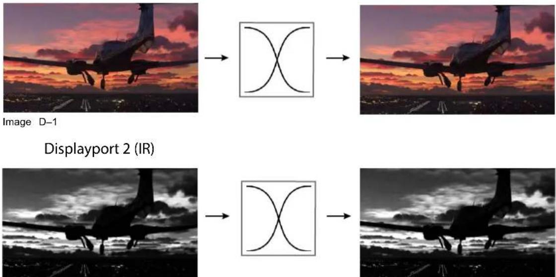
Image D-2
This is the default setup, and the properties of the input is as follows:
| Property | Value |
| image.connector.displayport1.colorcomponent.red RED_IN | |
| image.connector.displayport1.colorcomponent.green GREEN_IN | |
| image.connector.displayport1.colorcomponent.blue BLUE_IN | |
| image.connector.displayport2.colorcomponent.red RED_IN | |
| image.connector.displayport2.colorcomponent.green GREEN_IN | |
| image.connector.displayport2.colorcomponent.blue BLUE_IN |
D.2 Cloned image with full RGB input
Cloned image with full RGB input
In this setup the image is rendered for visible light. It has full RGB information. In this setup there is also requested to take the red color component on the input for the IR channel and fully saturate the DMD w component.
Display port 1 (VL) Color mapping DMD
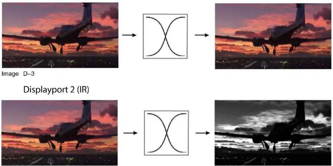
Image D-4
To achieve this result, use the following settings:
| Property | Value |
| image.connector.displayport1.colorcomponent.red RED_IN | |
| image.connector.displayport1.colorcomponent.green GREEN_IN | |
| image.connector.displayport1.colorcomponent.blue BLUE_IN | |
| image.connector.displayport2.colorcomponent.red RED_IN | |
| image.connector.displayport2.colorcomponent.green RED_IN | |
| image.connector.displayport2.colorcomponent.blue RED_IN |
D.3 Cloned inputs with only green content for IR
Cloned inputs with only green content for IR
In this setup, the input is a fully saturated green and white image, well suited for the IR channel. In this portion of the green image is extracted and applied to the red channel for visible light also. Note that the of the visible light source must be dimmed to achieve the desired effect.
Display port 1 (VL) Color mapping DMD
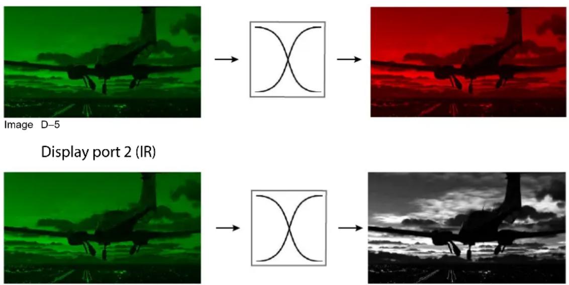
Image D-6
| Property | Value |
| image.connector.displayport1.colorcomponent.red GREEN_IN | |
| image.connector.displayport1.colorcomponent.green OFF | |
| image.connector.displayport1.colorcomponent.blue OFF | |
| image.connector.displayport2.colorcomponent.red GREEN_IN | |
| image.connector.displayport2.colorcomponent.green GREEN_IN | |
| image.connector.displayport2.colorcomponent.blue GREEN_IN |
Regulatory
E
E.1 Trademark notice....256
E.2 Product privacy statement....257
E.1 Trademark notice
HDMI™
The terms HDMI, HDMI High-Definition Multimedia Interface, HDMI trade dress and the HDMI Logos are trademarks or registered trademarks of HDMI Licensing Administrator, Inc.
DisplayPort™
DisplayPort™, the DisplayPort™ logo and DisplayPortHDR™ logo are trademarks owned by the Video Electronics Standards Association (VESA®) in the United States and other countries.
HDBaseT™
HDBaseT™ and the HDBaseT Alliance logo are trademarks of the HDBaseT Alliance.
PJLink™
The PJLink ^™ is a registered trademark of Japan Business Machine and Information System Industries Association.
DLP™
DLP® and the DLP logo are registered trademarks of Texas Instruments.
BrilliantColor™
BrilliantColor ^™ is a registered trademark of Texas Instruments.

All other trademarks and registered trademarks are trademarks or registered trademarks of their respective holders. In this manual, ^™ and ^® marks are not specified.
E.2 Product privacy statement
About
Learn more about Barco's Product Privacy Statement:
https://www.barco.com/en/about/trust-center/product-privacy-statement.
Which data is captured and why
Following data ^20 is captured for general secure operation of the product.
- IP addresses
- User ID information
- Date and time information
• Mobile network information
• Network configuration information
• Device identification information
• Device operational conditions
• Device environmental conditions
• Device performance metric
• Device configuration information
- Resolution
- Brightness
• Device input configuration
- Active inputs
- Input resolution
Data retention mechanism
An administrator should modify or delete a user (upon user request, or when the user does not work for company anymore), either via the Users feature, or via a factory reset executed as administrator.
Logs may contain user names and IP addresses and are subject to the retention policy, but cannot be de by the user. The user can send a request to dataprotection@barco.com.
Glossary
Active Stereo
Field sequential 3D (also known as active 3D or "Active Stereo") is a technique of displaying stereoscopic images. It works by only presenting the image intended for the left eye while blocking the right eye's view presenting the right-eye image while blocking the left eye, and repeating this so rapidly that the interruption do not interfere with the perceived fusion of the two images into a single 3D image.
This system setup uses liquid crystal shutter glasses (also known as active shutter glasses). Each eye's gl contains a liquid crystal layer which has the property of becoming opaque when voltage is applied, being otherwise transparent. The glasses are controlled by a timing signal that allows the glasses to alternately block one eye, and then the other, in synchronization with the refresh rate of the screen. The timing synchronization to the video equipment may be achieved via a wired signal or via wireless communication, this by using either an infrared or radio frequency (e.g. Bluetooth, DLP link) transmitter.
Default Gateway
A router that serves as an entry point into and exit point out of a network. For example, a local network may need a gateway to connect it to a wide area network (WAN) or to the Internet.
DHCP
Dynamic host configuration protocol. DHCP is a communications protocol that lets network administrators manage centrally and automate the assignment of IP addresses in an organization's network. Using the Internet Protocol, each machine that can connect to the Internet needs a unique IP address. When an organization sets up its computer users with a connection to the Internet, an IP address must be assigned each machine. Without DHCP, the IP address must be entered manually at each computer and, if compute move to another location in another part of the network, a new IP address must be entered. DHCP lets network administrator supervise and distribute IP addresses from a central point and automatically sends a new IP address when a computer is plugged into a different place in the network.
IG PixelShift
Image Generator Pixel Shift, hereafter referred to as IG pixel shift, is a method for achieving 4K resolution using the 4K actuator, where the phase offset between 2 subframes is generated by the source (the Imag Generator, or IG). When the IG renders the subframes, the exact position of the rendered objects in the model is known and the correct viewpoint for all objects is exact. This instead of the projector applying st filtering on the resulting 4K images to guess the subframes.
Image Generator (IG)
An image generator (IG) creates visual scenes of a simulated environment from the perspective of a participant. The visual scenes can be displayed on multiple simulation projectors in a dome setup. The sce
can be rendered in the visible spectrum for an "out-the-window" experience, or in other wavelengths to simulate optical sensors. An image generator generates scenes very quickly to maintain a realistic sense of motion for the participant.
IP
Internet Protocol. The network layer of TCP/IP. Required for communication with the internet.
Latency
The total time from the first pixel is coming in on an input source, until the first light representing that pi visible on the screen. This includes the transport delay. The value is normally given in milliseconds.
MAC address
Media Access Control address. Unique hardware number, used in combination with the IP-address to connet to the network (LAN or WAN).
Passive Stereo
Passive Stereoscopic 3D (also known as "Passive Stereo") is the standard method of creating the illusion of depth in an image, by means of stereopsis for binocular vision.
To present stereoscopic pictures, two images are projected superimposed onto the same screen through polarizing filters or presented on a display with polarized filters. For Digital Cinema, a silver screen is used that polarization is preserved. On most passive displays every other row of pixels are polarized for one eye the other. This method is also known as interlacing.
The viewer wears glasses which contain a pair of opposite polarizing filters. As each filter only passes light which is similarly polarized and blocks the opposite polarized light, each eye only sees one of the images the effect is achieved.
PQ
Perceptual Quantizer (PQ) is a non-linear electro-optical transfer function (EOTF) that allows for the display High Dynamic Range (HDR) content with a luminance level of up to 10 000 cd/m ^2 and can be used with Rec. 2020 color space.
Subnet mask
A number that is used to identify a subnetwork so that IP addresses can be shared on a local area net
Transport delay
The added delay in the image processing chain. The value is the number of lines relative to the output resolution.
Index
Numbers/Symbols
16:9 to center function 69
3D setup 124
Connection possibilities 125
IG pixel shift 125
IG pixel shift NightVision 125
Image Generator (IG) 125
Process 125
3D Setup
Active 3D 124
Active stereo 124
Passive 3D 124
Passive Stereo 124
A
Active 3D
setup 126
B
Blending
Black level adjustment
Files 116
Black level files 116
BrilliantColor™ 245
F400 249
F70 247
FL40 / FS40 246
1600 250
C
Cinemascope
Cropping 56
Cropping explanation 56
Cloned image with full RGB input
Color component mapping 253
Cloned inputs with only green content for IR
Color component mapping 254
Color component mapping 251
Cloned image with full RGB input 253
Cloned inputs with only green content for IR 254
Default setup 252
Configuration (general)
Process overview 19
Convergence 200
Cropping
Cinemascope 56
Cropping presets 58
Manual cropping 59
D
Dashboard menu 225
Overview 226
Dashboard screens 15
Default setup
Color component mapping 252
Display
Multiple sources 32
Single source 30
DMX chart
Basic 231
Extended 234
DMX Chart
Input mapping 230
DMX charts 229
E
Electronic convergence 200
End-user license agreement 219
EULA 219
External cooler 185
F
First start 11
Product registration 11
Select language 11
Flex brightness 195
Flex resolution 197
Front XLR connector
Control 182
G
Gamma type
DICOM 48
sRGB 48
General 9
|
Image 41
Advanced settings 61
BrilliantColor™ 67
DynaBlack 66
Dynamic contrast 66
HDR 64
Night vision 70
PQ 64
Realcolor P7 61
P7 presets 62
Smear reduction 68
Brightness 43
Contrast 42
Digital shift 53
Digital zoom 53
Digital zoom and shift 53
Gamma 47–48
Gamma correction 47
RealColor P7
Custom P7 61
Saturation 44
Sharpness 45
Tilted brightness uniformity correction 50
Image cropping
Auto cropping 57
Introduction 56
Insallation
Warping
4 Corners 96
Installation 73
3D Setup 124, 126
Blend and mask 107
Basic blend 108
Black level 113
RGB gain 115
Blend mask 109
RGB gain adjustment 115
Blend andmask
Blend files 112
Blending 107
Illumination 119
IR Illumination 121
Lens configuration 82
Masking 107
Nightvision 121
Optics 82
Dynamic focus V2 83
Focus 82
Focus drift compensation 83
Iris 88
Lens shift 82
Shift 82
shift to center 87
Shutter mode 89
Zoom 82
Position 74
Camera 75
Center motorized frame 78
Center rigging frame 78
Distance meter 75
Laser range finder 75
Laser ranging 75
Motorized frame 79
Orientation 74
Rigging frame 79
Scaling 91
Warping 93
Bow 98
Latency Control 104
On/Off 93
Screen size 93
Transport delay 104
Warp files 103
Introduction 10
Menu features 13
Navigation 17
IR Pixel Shift
setup 126
L
Lens
Adjustment
Calibration 194
Lens adjustment
Calibration 194
Login 23, 26
Logout 23
M
Macro
Delete 136
Edit 134
New 132
Preset 134
Motorized frame
Front XLR connector 182
Multiple sources
Display 32
N
Nightvision
Swap channels 70
NightVision
setup 126
0
Open source licenses 219
Output resolution 63
P
PJLink 161
Command List 242
Commands 241
Prerequisites
projector configuration 20
Privacy 257
Product registration
Overview 140
workflow 141
Product Registration
Manual registration 142
QR code 142
Profile
Delete 136
New 132
Profiles 129
Edit 134
Introduction 130
Preset 134
Settings 130
Projector configuration
Prerequisites 20
process overview 19
Projector control
DMX 159
Front XLR connector 182
PJLink 161
Trigger output 165
Projector position
Tilt sensor 77
Projector Profile 129
R
RealColor P7
P7 presets 62
Regulatory 255
Reset
3D settings 190
All 190
Blending 190
DMX 190
Features 190
Illumination 190
Image 190
Network settings 190
Optics 190
Orientation 190
Other 190
Projector Profiles 190
Test Patterns 190
User Interface 190
User Interface settings 190
Warping 190
S
Scheduler 175
About 175
Add command 175
Clear all 178
Delete command 178
Edit command 178
New command 175
Security
Camera preview 204
Custom Test pattern 205
Source preview 203
Service
convergence 200
Electronic convergence 200
Settings 139
Advanced
Color 206
laser banks statistics 213
Laser pulsing 209
Optical filter 212
Pixel shift 211
Statistics 208
Capture mode 187
Communication 147
Custom projector name 149
HDBaseT ^TM
Automatic setup 157
Manual setup 158
Host name 149
IR control 147
Broadcast address 147
IR sensors 148
Projector address 147
LAN
Automatic setup 152
Manual setup 152
LAN setup
Introduction 150
Network
introduction 150
Network setup 150
Remote control 147
Broadcast address 147
IR sensors 148
Projector address 147
Trigger control 165
Trigger output 165
Wi-Fi
Automatic setup 153
Manual setup 155
Communicatoin
GSM 164
SIM card activation 164
Communicaton
DMX 159
Date and time 171
Automatically 171
Manually 173
End-user license agreement 219
General 219
EULA 219
Open source licenses 219
Maintenance 190
Advanced 203
Diagnostics 203, 216
Security 203
Power saving settings
Auto stanby 181
Product registration 140
Service
Color Wheel 207
Laser driver calibration 210
Tilt sensor calibration 214
TIM curing 215
TIM heating 215
System 185
Cooling 185
User interface 167
Backlight
LCD display 169
Stealth mode 169
Distance 168
Temperature 168
Themes 167
Units 168
SIM card
Blocked 164
Single source
Display 30
Smear reduction 245
Smear Reduction
F400 249
F70 247
FL40 / FS40 246
Solarization
Capture mode 187
Remove 187
Source 29
Connector settings 35
Configure override 37
No source image 39
Single source 30
Status screens 15
Stitched layouts 32
System settings 139
Auto dimming 180
Language 167
Power saving settings 180
Auto dimming 180
User interface
language 167
System Settings
Factory reset 190
Flex brightness 195
Flex resolution 197
Frame 199
Frame Calibration 199
Lens adjustment
Calibration 194
Lens features 189
Operational mode
Silent mode 185
T
Test patterns 221
Test Patterns 222
Trademarks 256
U
User authentication 24, 26
User rights 23
W
Weekly schedule 175

- Product revision
- Copyright ©
- Trademarks
- Changes
- Patent protection
- Product Security Incident Response
- Disclaimer on screenshot images used in this manual
- Software License Agreement
- Terms and Conditions:
- Disclaimer of Warranty:
- Table of contents
- General 9
- Projector configuration process overview....19
- User rights and logging in....23
- Source 29
- Image 41
- Installation 73
- Configuring the projector position....74
- Configuring optics....82
- Scaling modes 91
- Warping 93
- Blending & masking....107
- Illumination 119
- IR illumination – Night vision functionality 121
- 3D projection 124
- Projector profiles 129
- Settings 139
- Product registration.... 140
- Communication....147
- User interface 167
- Date and time 171
- Scheduler 175
- Power settings 180
- System 185
- Lens features 189
- Maintenance....190
- General 1
- Introduction
- About this manual
- About the Pulse On-Screen Display (OSD)
- First start of the software
- Select UI language
- Product Registration
- Using the UI elements
- Interacting with UI elements
- Scrolling through menus
- Toggling sliders
- Using the on-screen keyboard
- General
- Dashboard screens
- Dashboard Screens
- Panel
- Explanation
- Functions dashboard page explanation
- Navigation
- Navigation using the Pulse RCU
- Navigating using the LCD touch display
- Last chosen menu
- Projector configuration process overview
- 2
- About this chapter
- Prerequisites
- Overview
- List of prerequisites
- Process overview
- Projector configuration process
- User rights and logging in
- 3
- User accounts and security
- About authentication
- User group credentials
- Password and pin authentication for user group "service partner"
- User authentication
- Location and availability
- Accessing the advanced settings
- How to login
- How to logout
- Source
- 4
- Displaying a single source
- About selecting a source
- How to select?
- Shortcut buttons
- Displaying multiple sources: Stitched layouts
- About stitched layouts
- Possible stitched layouts
- How to select a stitched layout
- Connector settings
- About connector settings
- How to configure a connector
- Configure override
- About overriding the connector configuration
- How to override the configured connector
- No source image
- What happens when no valid signal is selected
- How to change
- Image
- 5
- Adjusting contrast
- About contrast
- How to set up contrast
- Adjusting brightness
- About brightness
- How to set up brightness level
- Adjusting the saturation
- About saturation
- How to set up saturation level
- Adjusting the sharpness
- About sharpness
- How to adjust the sharpness
- Adjusting the gamma correction
- About gamma correction
- How to adjust
- Setting the desired gamma type
- About gamma types
- Gamma types for residential models
- Exception when using an HDR source
- How to adjust the gamma type?
- Tilted brightness uniformity correction
- What is tilted brightness uniformity correction?
- How is the correction applied?
- Required tools
- How to adjust brightness across the screen
- Digital zoom and shift
- What can be done?
- The effect of digital zoom
- The effect of digital shift
- Digital shift and zoom
- Cinemascope – Cropping the image
- Introduction to Cinemascope and image cropping
- About Cinemascope and home media releases
- About image cropping
- Image cropping - auto cropping
- Auto aspect ratio detection
- Watermarks and graphic content in the horizontal black bars
- How to use auto aspect cropping
- Image cropping - using aspect ratio presets
- Available cropping presets
- How to use the aspect ratio presets
- Image cropping - manual cropping
- About manual cropping
- How to perform manual cropping
- Advanced image setting
- RealColor P7 - Custom P7 settings
- Purpose
- How to set custom P7 values
- RealColor P7 - Presets
- How to choose one of the P7 presets
- Setting the output resolution
- 4K-UHD versus Native 4K (N4K)
- How to determine the desired output resolution
- How to choose the output resolution
- Displaying HDR content
- PQ
- How to properly display HDR content?
- Dynamic contrast
- DynaBlack: What is Dynamic contrast?
- How to set the dynamic contrast?
- BrilliantColo™
- About BrilliantColo™
- BrilliantColor™ options
- How to select a BrilliantC01nonode
- Smear reduction
- Location & availability
- About smears and smear reduction
- Smear reduction options
- How to activate smear reduction
- Cropping the image to 16:9 centered
- About the 16:9 Centered functionality
- How to activate a centered 16:9 image
- Night vision
- About
- How to swap channels
- Installation
- 6
- Configuring the projector position
- Note regarding the position menu
- Orientation
- How to set the correct orientation
- Laser ranging
- How to measure the distance between projector and screen?
- How to verify the measured distance?
- Tilt sensor
- When to use the tilt sensor menu
- About Pitch & Roll
- How to read the tilt sensor values
- Manipulating the rigging frame, center position
- Using the front XLR connector on QDX, UDX and UDM
- How to return the motorized frame to center position?
- Manipulating the motorized rigging frame
- How to manipulate the rigging frame?
- Configuring optics
- Note regarding the Optics menu
- Optical zoom and focus
- About the Zoom and focus menu
- How to configure zoom and focus
- Configuring lens shift
- Vertical and Horizontal Shift
- Configuring dynamic focus on UST lens
- About dynamic focus
- About the reference points
- Guidelines
- How to add reference points?
- Shift to center
- How force a lens to center position
- Press the CONFIRM button.
- Configuring the Iris
- About the iris
- Lens iris
- Illumination iris
- Shutter mode
- About the shutter
- How to set shutter mode
- Scaling modes
- About scaling modes
- Setting a scaling mode
- Warping
- About warping
- Warping - on/off
- About warping on/off
- How to toggle
- Warping - Screen size
- About (Warp) screen size adjustment
- Using the screen aspect ratio presets
- Click Apply.
- How to adjust the image with pixels?
- Click Apply.
- Warping - 4 corners adjustment
- About 4 Corners adjustment
- How to adjust the image?
- Warping - Bow
- About bow adjustment
- Angle and linearity (length) in bow warping
- Symmetric bow correction
- Asymmetric bow correction
- Warping - Warp files
- About custom warp files
- How to activate an uploaded warp grid?
- Warping - Latency control in a multi projector setup
- Transport delay
- Latency
- Functional description
- How to configure transport delay?
- Blending & masking
- About blending
- Waiting period and blend maintenance period
- Blend, mask and black level icon
- Basic blend
- How to set up a basic blend zone?
- Blend mask
- About masking and blending width or height
- How to set up basic blend zones?
- Example of the use of blending
- Blend files
- About custom blend files
- Blend file size limitations
- How to activate an uploaded blend configuration file?
- Black level adjustment
- About adjusting the black level
- How to adjust the black level
- RGB gain adjustment
- About RGB gain adjustment
- How to perform an RGB adjustment
- Black level files
- About custom black level files
- Black level file size limitations
- How to activate an uploaded Black Level adjustment file?
- Illumination
- About CLO mode
- How to adapt the power
- IR illumination – Night vision functionality
- Displaying infrared
- How to achieve Night Vision mode
- How to enable Night Vision
- 3D projection
- 3D setup
- About Active Stereo & Passive Stereo
- Passive Stereo
- Active Stereo
- Projection method used
- Image Generators and IG pixel shift
- Image Generator (IG)
- IG PixelShift
- About IG pixel shift
- IG pixel shift in Night Vision mode
- Setup process 3D projection
- How to setup 3D projection?
- Connection possibilities
- Connecting with the projector connection panel
- Connecting with the quad combo input panel
- Connecting with the quad DP 1.2 Input pane
- 3D Setup
- Why change the 3D setup?
- Choosing the desired output mode
- Extra output modes for simulation and stealth projectors
- How to adjust the projector to the 3D emitter?
- Projector profiles
- 7
- Profiles introduction
- About Profiles
- Available profile settings
- Saving the current projector settings in a profile
- Assigning a projector profile to a preset
- Deleting a projector profile
- How to delete a profile
- Settings
- 8
- Product registration
- About product registration
- IoT functionality
- Models
- Product registration workflow
- Workflow
- Methods
- Pulse OSD:
- Pulse Prospector:
- Pulse Mobile App:
- Projector Toolset for Pulse:
- Web Communicator:
- About the mandatory registration for UDM, Njord and Hodr
- Product registration for Pulse OSD using the Barco Pulse Mobile app
- How to register using the QR code
- Manual product registration
- How to register manually
- Activate your Barco product
- Communication
- Remote control
- Remote control - Broadcast address
- About broadcast address
- How to change the broadcast address
- Remote control - Projector address
- About individual projector address
- Remote control - IR sensors
- How to disable
- Host name - Custom projector name setup
- How to set a different Host name
- Network setup
- About a network connection
- Introduction to a Network connection
- DHCP
- IP
- Subnet mask
- Default Gateway
- MAC address
- What should be set up for an Ethernet address?
- Security when using a network
- About LAN over WiFi
- About LAN over HDBaseT
- Wired IP address - Automatic setup
- How to automatically set up the IP address
- Wired IP address set up - Manual setup
- How to manually set up the IP address
- Wi-Fi IP address - Automatic setup
- How to connect to a wireless network?
- Wi-Fi IP address - Manual setup
- How to manually set up the Wi-Fi IP address
- LAN over HDBaseMP address - Automatic setup
- LAN over HDBaseMP address - Manual setup
- DMX
- DMX control methods
- Ways to control the projector via DMX
- How to set up DMX?
- PJLink
- About PJLink
- What can be done
- How to activate PJLink
- GSM configuration
- When to use the GSM menu
- About the SIM card PIN code
- How to activate
- Trigger outputs control
- About the trigger outputs
- How to enable or disable
- User interface
- Changing the User Interface language
- How to change the language of the user interface
- In the User interface menu, select Language.
- Select the desired language and confirm. Choose one of the following:
- Themes
- About Themes
- How to select a different interface theme
- Units (measurement) system setup
- About the used measurement systems
- How to set a different metric system
- Controlling the backlight of the LCD Display
- What lighting can be controlled?
- Stealth Mode
- How to set the backlight
- Date and time
- Date and time setup - automatically
- About date and time
- To set date and time automatically
- Date and time setup - manually
- How to set time manually
- Scheduler
- About the projector scheduler
- About the scheduler
- How to open the scheduler
- Adding a new command in the scheduler
- How to add a new command
- Edit or Delete a command
- How to edit or delete a command
- Clearing the scheduler
- How to clear up the entire scheduler
- Power settings
- About the power saving features
- Auto dimming
- About Auto dimming
- How to set Auto dimming?
- Auto light source off
- About Auto light source off
- How to configure Auto dimming?
- Auto standby
- About Auto standby
- Availability standby modes
- How to configure standby mode?
- Controlling the front XLR connector
- About the front XLR connector
- Pinout of the front XLR connector
- Powering the front XLR connector
- How to enable or disable?
- System
- Setting up the external cooler
- Using the external cooler
- How to set up the external cooler
- Operational mode
- About operational mode and the trade-off triangle
- Implementation on UDX
- Implementation on UDM
- Implementation on 1600
- Implementation on QDX
- How to change the operational mode of the projector
- Capture mode
- Why use capture mode?
- How to enable Capture mode
- Lens features
- How to enable/disable
- Maintenance
- Factory reset
- What are the factory settings?
- How to reset all projector settings
- How to reset one or more projector settings
- Lens calibration
- How to calibrate
- Flex brightness
- About Flex Brightness
- Activating Flex brightness
- Flex codes
- Setting the Flex brightness
- Flex resolution
- Flex resolution usage
- Setting the resolution via OSD menu
- Rigging frame Calibration
- How to calibrate the motorized rigging frame
- Electronic convergence
- About convergence
- About the convergence test pattern
- How to adjust convergence electronically
- Advanced settings
- About the hidden menu features
- Security
- Security - Enable source preview
- About source preview
- How to enable source preview
- Security - Enable camera preview
- About camera preview
- How to enable Camera preview
- Security - Enable custom test pattern upload
- About custom test patterns
- How to enable Custom test pattern upload
- Service - RealColor calibration
- How to adjust the P7 native settings
- Service - Color wheel
- About the Color wheel
- How to fine-tune the color wheel
- Service - Statistics
- What can be seen?
- How to display the statistics
- Advanced settings - Laser pulsing calibration
- What is laser pulsing
- When to perform laser pulsing calibration
- Prerequisites
- Service - Laser driver calibration
- When to perform laser driver calibration
- How to perform a laser driver calibration
- Service - Pixel shift
- About pixel shift
- How to fine-tune the actuator
- Advanced settings - Optical filter
- How to
- Service - Status of the laser banks
- About failing laser banks
- How to check the status of the Laser Banks
- Service - Tilt sensor calibration
- About the tilt sensor calibration
- How to calibrate the tilt sensor?
- Service - TIM curing/heating
- About TIM curing
- How to activate a TIM curing process
- Creating a diagnostics package using the OSD
- Specifications USB flash drive
- How to download a diagnostics package
- General
- List of open source licenses
- About open source licenses
- How to find the open source licenses
- End-user license agreement (EULA)
- About the EULA
- How to find the EULA after accepting it
- Test patterns
- 9
- Test Patterns
- List of standard test patterns
- About the test pattern types
- How to use test patterns
- Dashboard
- 10
- Dashboard overview
- How to access the Dashboard menu
- Features on the first dashboard page
- Features on the second dashboard page (Functions)
- Features on the third dashboard page (About)
- DMX charts
- A
- A.1 DMX chart input module position
- About the input boards
- A.2 DMX charts, Basic
- A.3 DMX chart, Extended
- PJLink commands
- B
- B.1 PJLink Command list
- BrilliantColor™ and Smear reduction availability
- C
- C.1 Availability differences for FL40 / FS40
- About the differences
- BrilliantColor™ for FL40 / FS40
- Smear reduction for FL40 / FS40
- C.2 Availability differences for F70
- BrilliantColor™ for F70
- Smear Reduction options with color wheel type "VizSim"
- Menu variations with color wheel type "Color"
- Menu variations with color wheel type "Bright"
- C.3 Availability differences for F400
- Smear reduction for F400
- C.4 Availability differences for I600
- BrilliantColor™ for 1600
- Smear reduction for 1600
- Nightvision color component mapping
- D
- How infrared is displayed
- D.1 Default setup
- Default setup
- D.2 Cloned image with full RGB input
- Cloned image with full RGB input
- D.3 Cloned inputs with only green content for IR
- Cloned inputs with only green content for IR
- Regulatory
- E
- E.1 Trademark notice
- HDMI™
- DisplayPort™
- HDBaseT™
- PJLink™
- DLP™
- BrilliantColor™
- E.2 Product privacy statement
- Which data is captured and why
- Data retention mechanism
- Glossary
- Index
- Numbers/Symbols
- F
- G
- |
- L
- M
- N
- 0
- P
- R
- S
- T
- U
- W
Brand : Barco
Model : Balder
Category : Projector