
Thor+ - Projector Barco - Free user manual and instructions
Find the device manual for free Thor+ Barco in PDF.


| Product Type | Digital Cinema Projector |
| Model | Thor+ (DP4K-40LHC) |
| Weight | 240 kg (529 lbs) |
| Dimensions (W x D x H) | 1020 x 735 x 527 mm (approximate) |
| Power Supply (Star) | 200-240V/346-415V 3W+N+PE, 16A, 50-60Hz |
| Power Supply (Delta) | 200-240V 3W+PE, 28A, 50-60Hz |
| Light Source | RGB Laser (6-primary 3D) |
| Resolution | 4K UHD (4096 x 2160) |
| Brightness | Up to 40,000 lumens (typical) |
| Lens Options | Various available; see lens selection chapter |
| Cooling System | Liquid cooling with external chillers |
| Chiller Requirement | One chiller for Thor, two chillers for Thor+ |
| Safety Class | RG3 (IEC 62471-5:2015) |
| Hazard Distance | Depends on lens; e.g., 1.5 m at throw ratio 1 |
| Beam Stop Button | Yes, with quarter-turn reset |
| External Safety Interlocks | Two interlocks supported (SIL 4 / PLe) |
| Maintenance: Filter Cleaning | Monthly or as needed |
| Inputs (ICMP-X) | HDMI 2.0, SDI, DisplayPort, LAN, USB |
| Operating Temperature | 10°C to 30°C (50°F to 86°F) |
| Operating Humidity | 0% to 80% RH non-condensing |
Frequently Asked Questions - Thor+ Barco
User questions about Thor+ Barco
0 question about this device. Answer the ones you know or ask your own.
Ask a new question about this device
Download the instructions for your Projector in PDF format for free! Find your manual Thor+ - Barco and take your electronic device back in hand. On this page are published all the documents necessary for the use of your device. Thor+ by Barco.
USER MANUAL Thor+ Barco
natural_image
Technical line drawing of a rectangular industrial device with internal components and mounting feet (no text or symbols)Installation manual
Changes
Barco provides this manual 'as is' without warranty of any kind, either expressed or implied, including but not limited to the implied warranties or merchantability and fitness for a particular purpose. Barco may make improvements and/or changes to the product(s) and/or the program(s) described in this publication at any time without notice.
This publication could contain technical inaccuracies or typographical errors. Changes are periodically made to the information in this publication; these changes are incorporated in new editions of this publication.
The latest edition of Barco manuals can be downloaded from the Barco web site www.barco.com or from the secured Barco web site https://www.barco.com/en/signin.
Copyright ©
All rights reserved. No part of this document may be copied, reproduced or translated. It shall not otherwise be recorded, transmitted or stored in a retrieval system without the prior written consent of Barco.
BSMI Reporting Obligor Information / 報驗義務人資訊
Federal Communications Commission (FCC Statement)
This equipment has been tested and found to comply with the limits for a class A digital device, pursuant to Part 15 of the FCC rules. These limits are designed to provide reasonable protection against harmful interference when the equipment is operated in a commercial environment. This equipment generates, uses, and can radiate radio frequency energy and, if not installed and used in accordance with the instruction manual, may cause harmful interference to radio communications. Operation of this equipment in a residential area may cause harmful interference, in which case the user will be responsible for correcting any interference at his own expense
Changes or modifications not expressly approved by the party responsible for compliance could void the user's authority to operate the equipment
FCC responsible: Barco Inc.
3059 Premiere Parkway Suite 400
30097 Duluth GA, United States
Tel: +1 678 475 8000
EN55022/CISPR22 Class A ITE (Information Technology Equipment)
Class A ITE is a category of all other ITE which satisfies the class A ITE limits but not the class B ITE limits. Such equipment should not be restricted in its sale but the following warning shall be included in the instructions for use:
Warning : This is a class A product. In a domestic environment this product may cause radio interference in which case the user may be required to take adequate measures. Contact the installer.
Warning : This equipment is compliant with Class A of CISPR 32. In a residential environment this equipment may cause radio interference.
Product Security Incident Response
As a global technology leader, Barco is committed to deliver secure solutions and services to our customers, while protecting Barco's intellectual property. When product security concerns are received, the product security incident response process will be triggered immediately. To address specific security concerns or to
report security issues with Barco products, please inform us via contact details mentioned on https://www.barco.com/psirt. To protect our customers, Barco does not publicly disclose or confirm security vulnerabilities until Barco has conducted an analysis of the product and issued fixes and/or mitigations.
Patent protection
Please refer to www.barco.com/about-barco/legal/patents
Guarantee and Compensation
Barco provides a guarantee relating to perfect manufacturing as part of the legally stipulated terms of guarantee. On receipt, the purchaser must immediately inspect all delivered goods for damage incurred during transport, as well as for material and manufacturing faults Barco must be informed immediately in writing of any complaints.
The period of guarantee begins on the date of transfer of risks, in the case of special systems and software of the date of commissioning, at latest 30 days after the transfer of risks. In the event of justified notice of complaint, Barco can repair the fault or provide a replacement at its own discretion within an appropriate period. If this measure proves to be impossible or unsuccessful, the purchaser can demand a reduction in the purchase price or cancellation of the contract. All other claims, in particular those relating to compensation for direct or indirect damage, and also damage attributed to the operation of software as well as to other services provided by Barco, being a component of the system or independent service, will be deemed invalid provided the damage is not proven to be attributed to the absence of properties guaranteed in writing or due to the intent or gross negligence or part of Barco.
If the purchaser or a third party carries out modifications or repairs on goods delivered by Barco, or if the goods are handled incorrectly, in particular if the systems are operated incorrectly or if, after the transfer of risks, the goods are subject to influences not agreed upon in the contract, all guarantee claims of the purchaser will be rendered invalid. Not included in the guarantee coverage are system failures which are attributed to programs or special electronic circuitry provided by the purchaser, e.g. interfaces. Normal wear as well as normal maintenance are not subject to the guarantee provided by Barco either.
The environmental conditions as well as the servicing and maintenance regulations specified in this manual must be complied with by the customer.
Software License Agreement
You should carefully read the following terms and conditions before using this software. Your use of this software indicates your acceptance of this license agreement and warranty.
Terms and Conditions:
- No redistribution of the software is allowed.
- Reverse-Engineering. You may not reverse engineer, decompile, disassemble or alter this software product.
Disclaimer of Warranty:
This software and the accompanying files are sold “as is” and without warranties as to performance or merchantability or any other warranties whether expressed or implied. In no event shall Barco be liable for damage of any kind, loss of data, loss of profits, business interruption or other pecuniary loss arising directly or indirectly. Any liability of the seller will be exclusively limited to replacement of the product or refund of purchase price.
GNU-GPL code
If you would like a copy of the GPL source code contained in this product shipped to you on CD, please contact Barco. The cost of preparing and mailing a CD will be charged.
Trademarks
Brand and product names mentioned in this manual may be trademarks, registered trademarks or copyrights of their respective holders. All brand and product names mentioned in this manual serve as comments or examples and are not to be understood as advertising for the products or their manufacturers.
Table of contents
1 Welcome....9
1.1 About this manual....10
2 Safety Information 11
2.1 General considerations 12
2.2 Safety training to be provided by the installer....12
2.3 Important safety instructions 13
2.4 Safety precautions Hazardous Chemicals 17
2.5 Product safety labels....18
2.6 High Brightness precautions: Hazard Distance (HD) 20
2.7 HD for fully enclosed projection systems 22
2.8 HD in function of modifying optics 24
3 System overview 25
3.1 Thor 27
3.2 Chillers and hoses 28
3.3 Safety system 30
3.4 Communicator Touch Panel 31
3.5 Communicator PC version....33
3.6 Commander & Web Commander 34
4 Getting started 35
4.1 Installation requirements 36
4.2 Unpacking the projector 39
4.3 Initial inspection 40
5 Installation process 41
5.1 Installation process overview 42
6 Physical installation....45
6.1 Removing the transport protection bars....46
6.2 Positioning the projector at port window 46
6.3 Connecting the hoses with projector and chillers 49
6.4 Connecting the data cable with projector and chillers....51
6.5 Accessing the mains compartment....51
6.6 Connecting the external safety interlocks 53
6.7 Three phase power input configuration of the projector 54
6.8 Connecting the projector with the mains electricity 55
6.9 Power loop through to the projector electronics 56
6.10 Connecting a UPS to the projector electronics 57
6.11 Installing the Communicator Touch Panel 58
7 Lenses & Lens selection....61
7.1 Available lenses....62
7.2 Lens selection....62
7.3 Lens installation 63
7.4 Lens removal 65
7.5 Lens shift, zoom & focus 66
8 Input & Communication....69
8.1 Introduction....70
8.2 Projector Status 70
8.3 Laser Status....71
8.4 Local Keypad....72
8.5 Cinema Controller....74
9 ICMP(-X) 77
9.1 ICMP(-X) introduction....79
9.2 ICMP(-X) HDD 81
9.3 What are the possible HDD swaps 83
9.4 Installing a HDD into the ICMP(-X) 84
9.5 Removing a HDD from the ICMP(-X)....86
9.6 HDD status LEDs 87
9.7 ICMP(-X) status LEDs 88
9.8 ICMP(-X) device certificate....89
9.9 Obtaining the Barco ICMP(-X) certificate 91
9.10 ICMP(-X) configuration via Communicator....92
9.11 ICMP(-X) communication ports....93
9.12 ICMP(-X) source input ports 94
9.13 ICMP(-X) network streaming (Live IP) specifications 96
9.14 ICMP DisplayPort specifications 97
9.15 ICMP(-X) SDI specifications....98
9.16 ICMP(-X) HDMI 2.0 specifications 101
9.17 ICMP HDMI 1.4 specifications....104
9.18 ICMP(-X) reset....107
10 Starting up 109
10.1 Switching the Thor series projector ON....110
10.2 Switching the Thor series projector OFF 111
10.3 Projector ON/OFF cycle explained 112
11 Scheimpflug ....115
11.1 Scheimpflug introduction 116
11.2 Scheimpflug adjustment 117
11.3 Fixation of the Lens Holder front plate 120
11.4 Back Focal Length adjustment.... 121
12 Convergence 127
12.1 Convergence controls 128
12.2 Preparing for convergence adjustment 130
12.3 Converging the red pattern onto the blue pattern.... 131
12.4 Converging the green pattern onto the blue pattern 132
13 Calibration 135
13.1 Calibration process 136
13.2 White point calibration.... 137
13.3 Color gamut calibration.... 139
13.4 Luminance calibration 141
14 Preventative maintenance actions.... 143
14.1 1 month maintenance actions....144
14.2 3 month maintenance actions....144
15 Maintenance procedures 147
15.1 Check the dust filters 148
15.2 Vacuum cleaning of the dust filters 149
15.3 Washing and drying the dust filters.... 149
15.4 Cleaning the lens 150
15.5 Cleaning the exterior of the projector.... 151
15.6 Authorization to clear security warning on the projector 151
16 Removal and installation of the projector covers.... 153
16.1 Opening the front and rear cover doors 154
16.2 Removal of the top cover 154
16.3 Removal of the side covers.... 155
A Specifications....157
A.1 Specifications of the Thor.... 158
A.2 Specifications of the Thor+ 160
A.3 Specifications of the ICMP 163
A.4 Specifications of the ICMP-X 164
A.5 Dimensions of the Thor series projector 165
A.6 Technical Regulations 166
B Pin configurations 167
B.1 About General Purpose Inputs & Outputs (GPIO) 168
B.2 Pin configurations of the Cinema Controller communication ports....169
B.3 Pin configurations of the ICMP(-X) communication ports 171
C Environmental information 175
C.1 Disposal information.... 176
C.2 China RoHS compliance....176
C.3 Taiwan RoHS compliance 178
C.4 Turkey RoHS compliance 178
C.5 Contact information 179
C.6 Production address....179
C.7 Download Product Manual 179
Glossary 181
Index 185
Welcome 1
Congratulations
May we congratulate you on your purchase of a Barco Thor! It is our sincere wish that this digital projector meets up to your every expectation and that you thereby take a little time to page through this important manual. Familiarizing yourself with it's features, important safety instructions and necessary maintenance actions, will ensure you enjoy many years of reliable, trouble-free high quality performance.
Overview
• About this manual
1.1 About this manual
How to use this manual?
We suggest that you read over this manual before you install and use your Thor. Inside it, you will find important information regarding safety, installation and maintenance. We urge even the experienced user to take the necessary time to page through this manual. We believe everyone will benefit from this manual. Not in the least our editors, who will sleep more comfortably knowing their efforts have had their effect.

Some illustrations and descriptions in this document may be different than the product delivered. E.g. Illustrations with two chillers instead of one. For Thor series only one chiller has to be taken into account.
What's expected from you?
For your safety and in the interest of reliable, trouble-free, high quality performance, we urge the user/operator/service technician, to follow all instructions precisely. Follow the maintenance recommendations and procedures in this manual step by step to keep your projector in excellent condition. Doing so will directly impact the lifetime of your Thor.
If, after having read over these instructions, you experience difficulties, please contact your Barco service partner! They will do their best to assist you and get you up and running as soon as possible.
"Treat your Thor as your own and it will reward you with many trouble-free years of exquisite digital entertainment pleasure!"
Safety Information 2
About this chapter
Read this chapter attentively. It contains important information to prevent personal injury while installing and using your Thor series projector projector. Furthermore, it includes several cautions to prevent damage to your Thor series projector projector. Ensure that you understand and follow all safety guidelines, safety instructions and warnings mentioned in this chapter before installing and using the Thor series projector projector. After this chapter, additional “warnings” and “cautions” are given depending on the procedure. Read and follow these “warnings” and “cautions” as well.
Clarification of the term "Thor series" used in this document
When referring in this document to the term "Thor series" means that the content is applicable for following Barco products:
• THOR
• THOR+
Model certification name
• Thor : DP4K-20LHC
• Thor+: DP4K-40LHC

Barco provides a guarantee relating to perfect manufacturing as part of the legally stipulated terms of guarantee. Observing the specification mentioned in this chapter is critical for projector performance. Neglecting this can result in loss of warranty.
Overview
• General considerations
• Safety training to be provided by the installer
• Important safety instructions
• Safety precautions Hazardous Chemicals
• Product safety labels
• High Brightness precautions: Hazard Distance (HD)
• HD for fully enclosed projection systems
• HD in function of modifying optics
2.1 General considerations
General safety instructions
• Before operating this equipment please read this manual thoroughly and retain it for future reference.
• Installation and preliminary adjustments should be performed by qualified Barco personnel or by authorized Barco service dealers.
- All warnings on the projector and in the documentation manuals should be adhered to.
- All instructions for operating and use of this equipment must be followed precisely.
- All local installation codes should be adhered to.
Notice on safety
This equipment is built in accordance with the requirements of the international safety standards IEC60950-1, EN60950-1, UL60950-1 and CAN/CSA C22.2 No.60950-1, which are the safety standards of information technology equipment including electrical business equipment. These safety standards impose important requirements on the use of safety critical components, materials and insulation, in order to protect the user or operator against risk of electric shock and energy hazard and having access to live parts. Safety standards also impose limits to the internal and external temperature rises, radiation levels, mechanical stability and strength, enclosure construction and protection against the risk of fire. Simulated single fault condition testing ensures the safety of the equipment to the user even when the equipment's normal operation fails.
Notice on optical radiation
This projector embeds extremely high brightness (radiance) lasers; this laser light is processed through the projectors optical path. Native laser light is not accessible by the end user in any use case. The light exiting the projection lens has been defused within the optical path, representing a larger source and lower radiance value than native laser light. Nevertheless the projected light represents a significant risk for the human eye when exposed directly within the beam. This risk is not specific related to the characteristics of laser light but solely to the high thermal induced energy of the light source; which is equivalent with lamp based systems.
Thermal retinal eye injury is possible when exposed within the Hazard Distance (HD). The HD is defined from the projection lens surface towards the position of the projected beam where the irradiance equals the maximum permissible exposure as described in the chapter “Hazard Distance”.

WARNING: No direct exposure to the beam within the hazard distance shall be permitted, 62471-5:2015
RG3 IEC

CAUTION: Use of controls or adjustments or performance of procedures other than those herein may result in hazardous radiation exposure.
specified
Owner's record
The part number and serial number are printed on a label which is stuck on the respective part. Record these numbers in the spaces provided below. Refer to them whenever you call upon your Barco dealer regarding this product.
| Product article number | |
| Product serial number | |
| Dealer |
2.2 Safety training to be provided by the installer

WARNING: The installer is responsible that the user is instructed. The user will sign a document to confirm that the instructions have been received and understood.
Users definition
The Thor is intended for persons who have been instructed and trained by a skilled person (installer or service personnel) to identify energy sources that may cause injury and to take precautions to avoid unintentional contact with or exposure to those energy sources.
The skilled person must instruct the user about:
- High intensity light beam. The user must respect the exclusion zone, based on the light beam Hazard Distance (HD).
- Dangerous energy sources inside the projector. The user is not allowed to remove any cover from the projector.
- The installation, maintenance or service is for skilled persons only.
• The requirements for a restricted access location, an exclusion zone and a restriction zone.
Restricted access location
To protect untrained persons and children, the projector must be installed in a restricted access location. The definition of a restricted access location is a location for equipment where both of the following paragraphs apply:
- Access can only be gained by skilled persons (installer or service personnel) or persons who have been instructed and trained by a skilled person. The persons must have been instructed about the reasons for the restriction applied to the location and about the precautions that shall be taken.
- Access is only possible through the use of the tool or lock and key, or other means of security, and is controlled by the authority responsible for the location.
Why a restricted access location: This is a RG3 product. Based on international requirements, no person in allowed to enter the projected beam within the zone between the projection lens and the related Hazard Distance (HD). This shall be physically impossible by creating sufficient separation height or by placing optional barriers. Within the restricted area operator training is considered sufficient. The applicable separation heights are discussed in "High Brightness precautions: Hazard Distance (HD)", page 20.
Exclusion zone
The projector radiates heat on its external surfaces and from ventilation ducts during normal operation. Exposing flammable or combustible materials into close proximity of this projector could result in the spontaneous ignition of that material, resulting in a fire. For this reason, it is absolutely necessary to leave an exclusion zone around all external surfaces of the projector whereby no flammable or combustible materials are present:
- The exclusion zone must not be less than 40 cm (16 in).
Restriction zone
To protect untrained users and children against high intensity light beams, the light beam Hazard Distance (HD) shall be taken into account.
2.3 Important safety instructions
To prevent the risk of electrical shock
- This product is equipped with a five-terminal barrier strip for the connection of a 3W+N+PE or 3W+PE three phase power system.
- This projector should be operated from an AC power source. Ensure that mains voltage and capacity matches the projector electrical ratings.
• Electrical ratings for Star system (3W+N+PE):
- The cross-sectional area of the conductors in the power supply cord shall ^2 de mm ^2 , 10AWG to 8AWG.
- The electrical rating of the Thor+ projector is 200-240V/346-415V 3W+N+PE 16A 50-60Hz (Y connection) (Y connection).
- The electrical rating of the Thor projector is 200-240V/346-415V 3W+N+PE 10A 50-60Hz (Y connection) (Y connection).
- The building installation has to be provided with a circuit breaker of range 25A to 40A to protect the complete unit.
• Electrical ratings for Delta system (3W+PE):
- The cross-sectional area of the conductors in the power supply cord shall be 8 AWG.
- The electrical rating of the Thor+ projector is 200-240V 3W+PE 28A 50-60Hz (Δ connection) (Δ connection).
- The electrical rating of the Thor projector is 200-240V 3W+PE 15A 50-60Hz (Δ connection) (Δ connection).
-
The building installation has to be provided with a circuit breaker of 40A to protect the complete unit.
-
REMARK for Thor+ projector: In case of a Delta system (3W+PE) the circuit breakers rated lower than 40A can trip unwanted because of the internal laser power supply redundancy system. The projector remains working if one internal laser power supply module fails or is removed, but this results in a higher current in one mains power line. In case of very low line voltage (between 180V and 200V), and one failed or removed laser power supply, the line current can reach 35A.
- Installation according to the local electrical code and regulations by qualified technical personnel only. Do not defeat the purpose of the grounding.
• The cross-sectional area of the UPS inlet cord shall be not less than 0.75 mm ^2 or AWG 18. - The electronics of the projector (UPS INLET) must be powered either from a suitable UPS unit or from the power outlet socket (UPS OUTLET) provided on the projector. An adapted short power cord (2-pole 3-wire grounding) is added to the projector accessories to loop through the power from UPS OUTLET to UPS INLET.
- The provided power output socket (UPS OUTLET) on the projector may only be used to provide power to the projector electronics (UPS INLET). Never connect other devices to this power output socket.
- A readily accessible disconnect device must be incorporated externally to the equipment for removal of the power to the projector mains terminals.
- Disconnect the power to the projector mains terminals and unplug the power cord at UPS INLET for removal of all power from the projector.
- Warning: High leakage current. Earth connection essential before connecting supply.
- Do not allow anything to rest on the power cord. Do not locate this projector where persons will walk on the cord.
- Do not operate the projector with a damaged cord or if the projector has been dropped or damaged - until it has been examined and approved for operation by a qualified service technician.
- Position the cord so that it will not be tripped over, pulled, or contact hot surfaces.
- If an extension cord is necessary, a cord with a current rating at least equal to that of the projector should be used. A cord rated for less amperage than the projector may overheat.
- Never push objects of any kind into this projector through cabinet slots as they may touch dangerous voltage points or short circuit parts that could result in a risk of fire or electrical shock.
- Do not expose this projector to rain or moisture.
- Do not immerse or expose this projector in water or other liquids.
- Do not spill liquid of any kind on this projector.
- Should any liquid or solid object fall into the cabinet, unplug the set and have it checked by qualified service personnel before resuming operations.
- Do not disassemble this projector, always take it to an trained service person when service or repair work is required.
- Do not use an accessory attachment which is not recommended by the manufacturer.
- Lightning - For added protection for this video product during a lightning storm, or when it is left unattended and unused for long periods of time, remove all power from the projector. This will prevent damage to the projector due to lightning and AC power-line surges.
To prevent fire hazard
- Do not place flammable or combustible materials near the projector!
- Barco large screen projection products are designed and manufactured to meet the most stringent safety regulations. This projector radiates heat on its external surfaces and from ventilation ducts during normal operation, which is both normal and safe. Exposing flammable or combustible materials into close proximity of this projector could result in the spontaneous ignition of that material, resulting in a fire. For this reason, it is absolutely necessary to leave an “exclusion zone” around all external surfaces of the projector whereby no flammable or combustible materials are present. The exclusion zone must be not less than 40 cm (16") for all DLP Cinema projectors. The exclusion zone on the lens side must be at least 5 m. Do not
cover the projector or the lens with any material while the projector is in operation. Keep flammable and combustible materials away from the projector at all times. Mount the projector in a well ventilated area away from sources of ignition and out of direct sun light. Never expose the projector to rain or moisture. In the event of fire, use sand, _2 6O dry powder fire extinguishers. Never use water on an electrical fire.
Always have service performed on this projector by authorized Barco service personnel. Always insist on genuine Barco replacement parts. Never use non-Barco replacement parts as they may degrade the safety of this projector.
- Ensure no miss alignment can occur. Prolonged long time exposure of back wooden walls at close distance (< 20cm) can represent a fire risk. After alignment the projector shall be securely mounted to the pedestal.
- Slots and openings in this equipment are provided for ventilation. To ensure reliable operation of the projector and to protect it from overheating, these openings must not be blocked or covered. The openings should never be blocked by placing the projector too close to walls, or other similar surface. This projector should never be placed near or over a radiator or heat register. This projector should not be placed in a built-in installation or enclosure unless proper ventilation is provided.
- Projection rooms must be well ventilated or cooled in order to avoid build up of heat. It is necessary to vent hot exhaust air from projector and cooling system (chiller units) to the outside of the building.
- Let the projector cool completely before storing. Remove cord from the projector when storing.
To prevent battery explosion
- Danger of explosion if battery is incorrectly installed.
- Replace only with the same or equivalent type recommended by the manufacturer.
- For disposal of used batteries, always consult federal, state, local and provincial hazardous waste disposal rules and regulations to ensure proper disposal.
To prevent personal injury
- To prevent injury and physical damage, always read this manual and all labels on the system before powering the projector or adjusting the projector.
- Do not underestimate the weight of the projector. The projector weights ± 240kg ( ± 529 lbs). To prevent personal injury a hoisting tool should be used to lift the projector.
- To prevent injury, ensure that the lens, cooling system and all cover plates are correctly installed. See installation procedures.
- Warning: high intensity light beam. NEVER look into the lens! High luminance could result in damage to the eye.
- Warning: extremely high brightness projector: This projector embeds extremely high brightness (radiance) lasers; this laser light is processed through the projectors optical path. Native laser light is not accessible by the end user in any use case. The light exiting the projection lens has been defused within the optical path, representing a larger source and lower radiance value than native laser light.
Nevertheless the projected light represents a significant risk for the human eye when exposed directly within the beam. This risk is not specific related to the characteristics of laser light but solely to the high thermal induced energy of the light source; which is comparable with lamp based systems.
Thermal retinal eye injury is possible when exposed within the Hazard Distance. The Hazard Distance (HD) is defined from the projection lens surface towards the position of the projected beam where the irradiance equals the maximum permissible exposure as described in the chapter "High Brightness precautions: Hazard Distance (HD)", page 20.
- Based on international requirements, no person in allowed to enter the projected beam within the zone between the projection lens and the related Hazard Distance (HD). This shall be physically impossible by creating sufficient separation height or by placing optional barriers. Within the restricted area operator training is considered sufficient. The applicable separation heights are discussed in “High Brightness precautions: Hazard Distance (HD)”, page 20.
- The projector shall be installed in a restricted access room equipped with a key or security lock preventing untrained persons entering the Class 4 use zone.
- Before attempting to remove any of the projector's covers, disconnect the projector power cable from the mains electricity for removal of all power from the projector.
- When required to remove all power from the projector (e.g. during service), always disconnect the power from the projector mains terminals and UPS INLET connector. Use the disconnect device in the building installation to disconnect the power to the projector mains terminals, and unplug the power cord at the UPS INLET connector if the UPS INLET is separately powered.
-
Do not place this equipment on an unstable cart, stand, or table. The product may fall, causing serious damage to it and possible injury to the user.
-
Lenses, shields or screens shall be changed if they have become visibly damaged to such an extent that their effectiveness is impaired. For example by cracks or deep scratches.
- The associated Laser Safety responsible of the unit must evaluate the setup before the unit may be started.
- Never point or allow light to be directed on people or reflective objects within the HD zone.
• If the unit is shut down, remove the key control from the system; avoiding unauthorized startup.
• All operators shall have received adequate training and be aware of the potential hazards. - Strictly minimize the number of people who have access to the unit. The unit may never be operated without permission of the responsible for laser safety.
- When the projected light causes a dangerous situation the operator must hit the beam stop button which is located close to the control panel. The beam stop removes all power from the laser power supplies.
- Don't put your hand in front of the beam.
- Do not clean the port window when the projector is switched on.
- Position the hoses of the cooling system so that they will not be tripped over, pulled, or contact hot surfaces.
On servicing
- Do not attempt to service this product yourself, as opening or removing covers may expose you to dangerous voltage potentials and risk of electric shock.
• Refer all servicing to qualified service personnel. - Attempts to alter the factory-set internal controls or to change other control settings not specially discussed in this manual can lead to permanent damage to the projector and cancellation of the warranty.
-
Remove all power from the projector and refer servicing to qualified service technicians under the following conditions:
-
When the power cord or plug is damaged or frayed.
- If liquid has been spilled into the equipment.
- If the product has been exposed to rain or water.
- If the product does not operate normally when the operating instructions are followed. Adjust only those controls that are covered by the operating instructions since improper adjustment of the other controls may result in damage and will often require extensive work by a qualified technician to restore the product to normal operation.
- If the product has been dropped or the cabinet has been damaged.
- If the product exhibits a distinct change in performance, indicating a need for service.
- Replacement parts: When replacement parts are required, be sure the service technician has used original Barco replacement parts or authorized replacement parts which have the same characteristics as the Barco original part. Unauthorized substitutions may result in degraded performance and reliability, fire, electric shock or other hazards. Unauthorized substitutions may void warranty.
- Safety check: Upon completion of any service or repairs to this projector, ask the service technician to perform safety checks to determine that the product is in proper operating condition.
To prevent projector damage
- The air filters of the projector must be cleaned or replaced on a regular basis. Cleaning the booth area would be monthly-minimum. Neglecting this could result in disrupting the air flow inside the projector, causing overheating. Overheating may lead to the projector shutting down during operation.
- The projector must always be installed in a manner which ensures free flow of air into its air inlets.
- If more than one projector is installed in a common projection booth, the exhaust air flow requirements are valid for EACH individual projector system. Note that inadequate air extraction or cooling will result in decreased life expectancy of the projector as a whole as well as causing premature failure of the lasers.
- In order to ensure that correct airflow is maintained, and that the projector complies with Electromagnetic Compatibility (EMC) and safety requirements, it should always be operated with all of its covers in place.
- Slots and openings in the cabinet are provided for ventilation. To ensure reliable operation of the product and to protect it from overheating, these openings must not be blocked or covered. The openings should never be blocked by placing the product on a bed, sofa, rug, or other similar surface. This product should never be placed near or over a radiator or heat register. The device should not be placed in a built-in installation or enclosure unless proper ventilation is provided.
-
Ensure that nothing can be spilled on, or dropped inside the projector. If this does happen, switch off and remove all power from the projector. Do not operate the projector again until it has been checked by qualified service personnel.
-
Do not block the projector cooling fans or free air movement around the projector.
- Proper operation of the projector can only be guaranteed in table mounting. It is not permitted to use the projector in another position. See installation procedure for correct installation.
- Special care for Laser Beams: Special care should be used when DLP projectors are used in the same room as high power laser equipment. Direct or indirect hitting of a laser beam on to the lens can severely damage the Digital Mirror Devices in which case there is a loss of warranty.
- Never place the projector in direct sunlight. Sunlight on the lens can severely damage the Digital Mirror Devices™ in which case there is a loss of warranty.
- Save the original shipping carton and packing material. They will come in handy if you ever have to ship your equipment. For maximum protection, repack your set as it was originally packed at the factory.
- Disconnect the power to the projectors mains terminals before cleaning. Do not use liquid cleaners or aerosol cleaners. Use a damp cloth for cleaning. Never use strong solvents, such as thinner or benzine or abrasive cleaners, since these will damage the cabinet. Stubborn stains may be removed with a cloth lightly dampened with mild detergent solution.
- To ensure the highest optical performance and resolution, the projection lenses are specially treated with an anti-reflective coating, therefore, avoid touching the lens. To remove dust on the lens, use a soft dry cloth. For lens cleaning follow the instructions precisely as stipulated in the projector manual.
- Rated maximum ambient temperature _a =t 30°C (86°F).
- Rated humidity = 0% RH to 80% RH Non-condensed.
- An external frame must be used to stack projectors.
- For functionality and reliability, the projector requires accurate temperature control and cooling below ambient. Therefore a liquid cooling system is provided consisting of liquid circuits inside the projector which are connected via hoses to external chillers. Only chiller models and hoses exclusively developed for this application and approved by Barco are allowed to be used. Barco approved chillers models are listed on the Barco website.
- An adequate draining system must be coupled with the drain pipes at the bottom of the projector to collect and lead away the condensed water from the built-in air-dryers. The capacity of the draining system must meet the humidity conditions wherein the projector operates. The water drain must arrives into an 'open' water container!
Safety Data Sheets for Hazardous Chemicals
For safe handling information on chemical products, consult the Safety Data Sheet (SDS). SDSs are available upon request via safetydatasheets@barco.com.
2.4 Safety precautions Hazardous Chemicals
Cooling liquid: Blue antifreeze


Handling the cooling liquid:
• Not for household use.
- Keep out of reach of children.
• Harmful by oral intake.
- Avoid exposure to pregnant women.
- Avoid contact of the liquid with Eyes, Skin and Clothing.
- Avoid inhaling noxious fumes.
- Conserve the product in the original package and in a well ventilated room.
Personal protection rules:
- Handle the cooling liquid in a well ventilated room.
• Under no circumstances eat, drink and smoke while handling the liquid. - Wear gloves (Butyl rubber, PVC....) and goggles.
- Wear suitable protection clothing.
Cleansing agent: sodium carbonate crystals _2 C(OI _3 )


Handling the cleansing agent:
- Conserve the product in the original container in a cool, well ventilated place.
- Keep away from Incompatible materials: sources of ignition, direct sunlight.
- Keep container closed when not in use.
• After handling: Wash hands and other exposed areas with mild soap and water.
Personal protection rules:
- Handle the cleansing agent in a well ventilated area.
• Do not eat, drink or smoke during use. - Wear gloves (Butyl rubber, PVC....) and goggles.
- Wear suitable protection clothing.

WARNING: Before handling Hazardous Chemicals ensure that you have read and understood the safety instructions provided by the supplier of the chemical in the Safety Data Sheet.
Safety Data Sheets for Hazardous Chemicals
For safe handling information on chemical products, consult the Safety Data Sheet (SDS). SDSs are available upon request via safetydatasheets@barco.com.
2.5 Product safety labels
Light beam related safety labels
Label image Label description
Label location

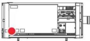
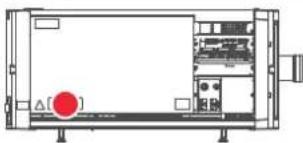
Hazard RG3: optical radiation warning symbol
natural_image
Technical line drawing of a mechanical or electronic device with no visible text, numbers, or symbols.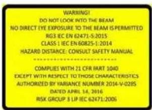
WARNING! DO NOT LOOK INTO THE LIGHT BEAM NO DIRECT EYE EXPOSURE TO THE BEAM IS PERMITTED. RG3 IEC EN 62471- 5:2015 CLASS 1 IEC EN 60825-1:2014 HAZARD DISTANCE: CONSULT SAFETY MANUAL. COMPLIES WITH 21 CFR 1040 EXCEPT WITH RESPECT TO THOSE CHARACTERISTICS AUTHORIZED BY VARIANCE NUMBER 2014-V-0285 DATED APRIL 14, 2016 RISK GROUP 3 LIP IEC 62471:2006
natural_image
Technical line drawing of a device chassis with front panel and internal components (no text or symbols)
natural_image
Technical line drawing of a mechanical or electrical enclosure with no visible text, numbers, or symbols.DANGER ! NE PAS REGARDER LE FAISCEAU EVITER TOUTE EXPOSITION DIRECTE DES YEUX AU FAISCEAU RG3 IEC EN 62471-5:2015 CLASS 1 IEC EN 60825- 1:2014 DISTANCE DE SECURITE : CONSULTER LE MANUEL DE SECURITE
| Label image Label description | Label location | |
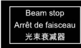 | Beam stop.Arrêt de faisceau.光束衰减器 | 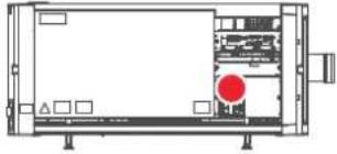 |
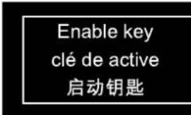 | Enable key.Clé de active.启动钥匙 | 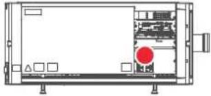 |
 | Hazard RG3: not for household use symbol | 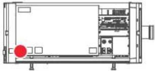 |
Electric related safety labels
| Label image | Label description | Label location |
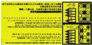 | Disconnect the power to the unit mains terminals and unplug power cord at UPS inlet for removal of all power from the unit.WARNING : HIGH LEAKAGE CURRENT EARTH CONNECTION ESSENTIAL BEFORE CONNECTING SUPPLY SEE INSTALLATION INSTRUCTIONS BEFORE CONNECTING TO THE SUPPLY.Déconnecter l'alimentation des bornes du réseau et déconnecter le câble de la prise UPS pour la coupure de toute l'alimentation de l'appareil. ATTENTION : COURANT DE FUITE ÉLEVÉ RACCORDEMENT À LA TERRE INDISPENSABLE AVANT LERACCORDEMENT AU RÉSEAU VOIR LA NOTICE D'INSTALLATION AVANT DERACCORDER AU RÉSEAU.断开放映机主电源端的电源并从UPS电源接入插座上拔下电源线.警告: 大漏,电流在接通电源之前必须先接地.在与电源连接前请查看安装说明书. | 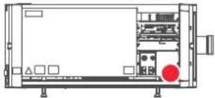 (located behind cover) (located behind cover) |
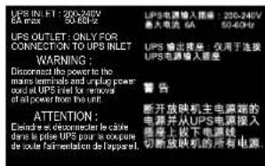
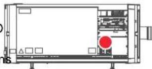
natural_image
Technical line drawing of a server rack with indicator lights and ports (no text or symbols)UPS INLET : 200-240V 6A max. 50-60Hz UPS OUTLET : ONLY FOR CONNECTION TO UPS INLET
WARNING : Disconnect the power to the main terminals and unplug power cord at UPS inlet for removal of all power from the unit.
2.6 High Brightness precautions: Hazard Distance (HD)
HD

Hazard Distance (HD) is the distance measured from the projection lens at which the intensity or the energy per surface unit becomes lower than the applicable exposure limit on the cornea or on the skin. The light beam is considered (to be) unsafe for exposure if the distance from a person to the light source is less than the HD.
Restriction Zone (RZ) based on the HD
The HD depends on the amount of lumens produced by the projector and the type of lens installed. See chapter "HD in function of modifying optics", page 24.
To protect untrained end users (as cinema visitors, spectators) the installation shall comply with the following installation requirements: Operators shall control access to the beam within the hazard distance or install the product at the height that will prevent spectators' eyes from being in the hazard distance. Radiation levels in excess of the limits will not be permitted at any point less than 2.0 meter (SH) above any surface upon which persons other than operators, performers, or employees are permitted to stand or less than 1.0 meter (SW) lateral separation from any place where such persons are permitted to be. In environments where unrestrained behavior is reasonably foreseeable, the minimum separation height should be greater than or equal to 3.0 meter to prevent potential exposure, for example by an individual sitting on another individual's shoulders, within the HD.
These values are minimum values and are based on the guidance provided in IEC 62471-5:2015 section 6.6.3.5.
The installer and user must understand the risk and apply protective measures based upon the hazard distance as indicated on the label and in the user information. Installation method, separation height, barriers, detection system or other applicable control measure shall prevent hazardous eye access to the radiation within the hazard distance.
For example, projectors that have a HD greater than 1 m and emit light into an uncontrolled area where persons may be present should be positioned in accordance with “the fixed projector installation” parameters, resulting in a HD that does not extend into the audience area unless the beam is at least 2.0 meter above th floor level. In environments where unrestrained behavior is reasonably foreseeable, the minimum separation height should be greater than or equal to 3.0 meter to prevent potential exposure, for example by an individual sitting on another individual's shoulders, within the HD. Sufficiently large separation height may be achieved by mounting the image projector on the ceiling or through the use of physical barriers.
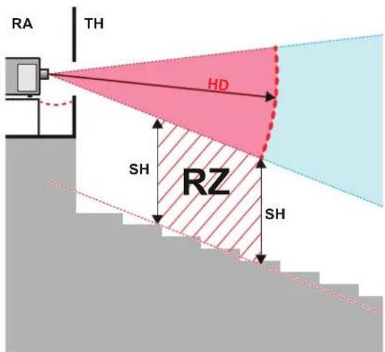
Image 2-1
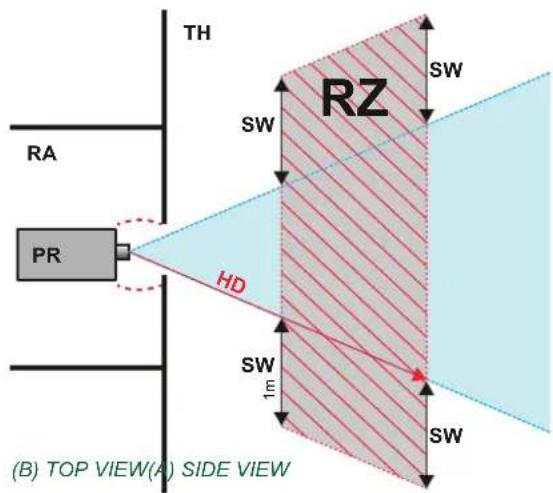
TH Theater.
RZ Restriction Zone in the theater.
SH Separation Height.
SWSeparation Width.
A Side view.
B Top view.
RA Restricted Access location (boot area of projector).
PR Projector.
Based on national requirements, no person is allowed to enter the projected beam within the zone between the projection lens and the related hazard distance (HD). This shall be physically impossible by creating sufficient separation height or by placing barriers. The minimum separation height takes into account the surface upon which persons other than operator, performers or employees are permitted to stand.
On Image 2-2 a typical setup is displayed. It must be verified if these minimum requirements are met. If required a restricted zone (RZ) in the theater must be established. This can be done by using physical barrier, like a red rope as illustrated in Image 2-2.
The restricted area sticker can be replaced by a sticker with only the symbol.
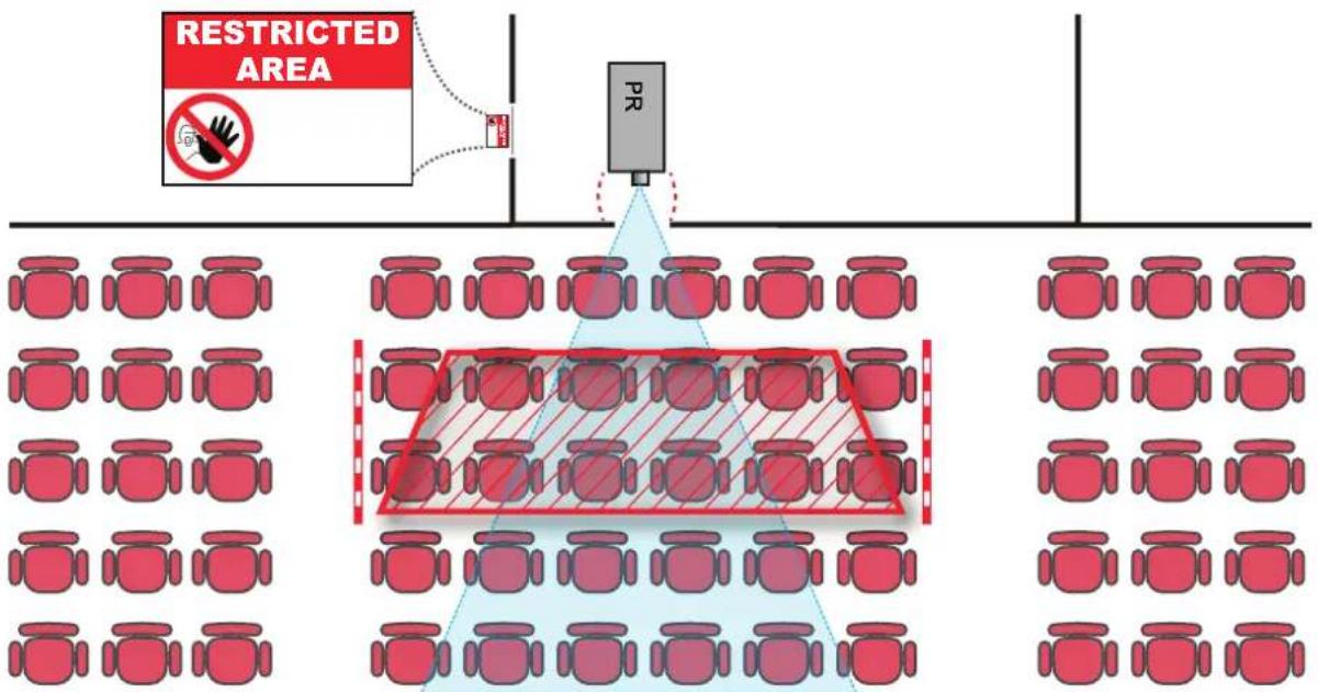
Image 2-2
USA market (For FDA notice No 57)
For LIPs (Laser Illuminated Projectors) installed in the USA market other restriction zone conditions apply.
LIPs for installation in restrained environment (cinema theaters) shall be installed at height vertically above the floor such that the bottom plane of the hazard distance zone shall be no lower than 2.5 meters above the floor. Horizontal clearance to the hazard distance zone shall be not less than 1 meter.
LIPs for installations in unrestrained environment (large venues,..) shall be installed at a height vertically above the floor such that the bottom plane of the Hazard distance Zone shall be no lower than 3 meters above the floor. Horizontal clearance to the hazard distance zone shall be not less than 2.5 meters. Any human access horizontally to the Hazard Zone, if applicable, shall be restricted by barriers. If human access is possible in an unsupervised environment, the horizontal or vertical clearances shall be increased to prevent exposure to the hazard distance zone.
In addition for temporary installations (e.g.: rental and staging, lease, events ...) the following requirements apply:
- This product can only be installed by Barco or sold or leased only to valid laser light show variance holders. In other words our installers are required to have an approved laser light show variance. Such installers may currently hold a valid variance for production of Class IIIb and IV laser light shows and/or for incorporation of the RG3 LIPs into their shows. Dealers and distributors are also required to obtain a valid laser light show variance.
- This product shall be located in such a way that all propagating beam paths within the Restriction Zone, and the audience can be directly observed at all times.
- Effects other than front or rear screen projections shall not be performed.
• Communication shall be maintained with other personnel assisting in surveillance of the LIP projection. - In the event of any unsafe condition, immediately terminates (or designate the termination) of LIP projection light.
Install one or more readily accessible controls to immediately terminate LIP projection light. The power input at the projector side is considered as a reliable disconnect device. When required to switch off the projector, disconnect the power cord at the projector side. In case the power input at the projector side is not accessible (e.g. truss mount), the socket outlet supplying the projector shall be installed nearby the projector and be easily accessible, or a readily accessible general disconnect device shall be incorporated in the fixed wiring.
Laser light shows can be requested via the FDA online eSubmitter portal or via FDA Form FDA Form 3147 referencing to Barco's variance approval 2014-V-0285.
The installation checklist for laser illuminated RG3 projectors must be fully completed after the installation and sent to pvg@barco.com. This checklist can be downloaded from the Barco website. Only when the installer is a valid laser light show variance holder the checklist should not be sent to Barco.
2.7 HD for fully enclosed projection systems
HD

Hazard Distance (HD) is the distance measured from the projection lens at which the intensity or the energy per surface unit becomes lower than the applicable exposure limit on the cornea or on the skin. The light beam is considered (to be) unsafe for exposure if the distance from a person to the light source is less than the HD.
Restriction Zone (RZ) based on the HD
The projector is also suitable for rear projection applications; projecting a beam onto a defuse coated projection screen. As displayed in Image 2-3 two areas should be considered: the restricted enclosed projection area (RA) and the observation area (TH).
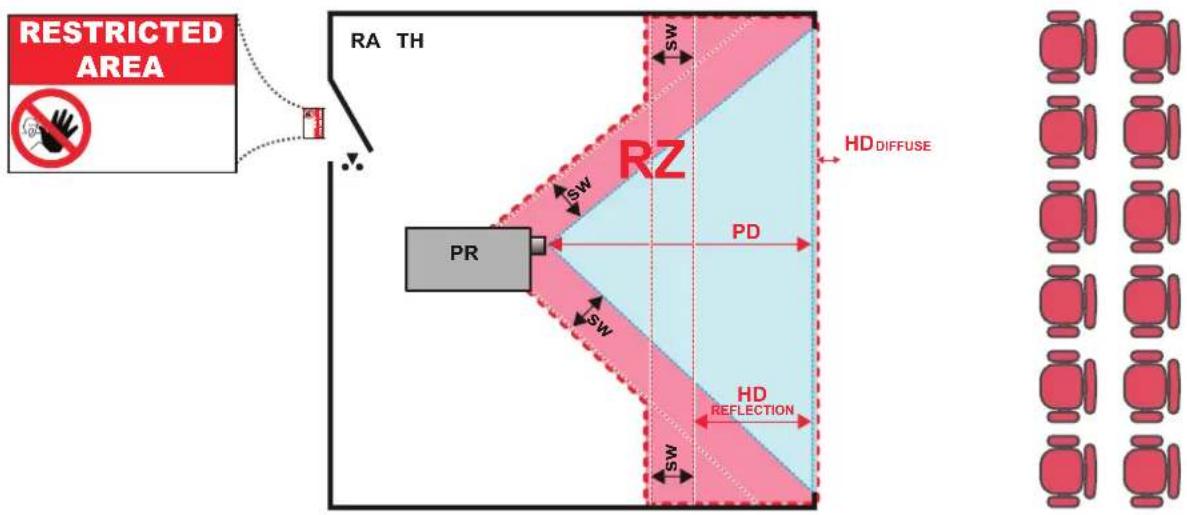
Image 2-3
RA Restricted Access location (enclosed projection area).
PR Projector.
TH Theater (observation area).
RZ Restriction Zone.
PD Projection Distance.
SWSeparation Width. Must be minimum 1 meter.
For this type of setup 3 different HD shall be considered:
- HD as discussed in "High Brightness precautions: Hazard Distance (HD)", page 20, relevant for intrabeam exposure.
- HD _reflection : the distance that has to be kept restrictive related to the reflected light from the rear projection screen.
- HD _diffuse : the relevant distance to be considered while observing the diffuse surface of the rear projection screen.
As described in "High Brightness precautions: Hazard Distance (HD)", page 20, it is mandatory to create a restricted zone within the beam areas closer than any HD. In the enclosed projection area the combination of two restricted zones are relevant: The restricted zone of the projected beam toward the screen; taking into account 1 meter Separation Width (SW) from the beam onward. Combined with the restricted zone related to the rear reflection from the screen (HD), also taking into account a 1 meter lateral separation.
The HD _reflection distance equals 25% of the difference between the determined HD distance and the projection distance to the rear projection screen. To determine the HD distance for the used lens and projector model se chapter “HD in function of modifying optics”, page 24.
$$ \mathrm{HD} _ {\text { reflection }} = 2 5 \% (\mathrm{HD} - \mathrm{PD}) $$
The light emitted from the screen within the observation shall never exceed the RG2 exposure limit, determined at 10 cm. The dHdSe can be neglected if the measured light at the screen surface is below 5000 cd/m² or 15000 LUX.
2.8 HD in function of modifying optics
Hazard Distance
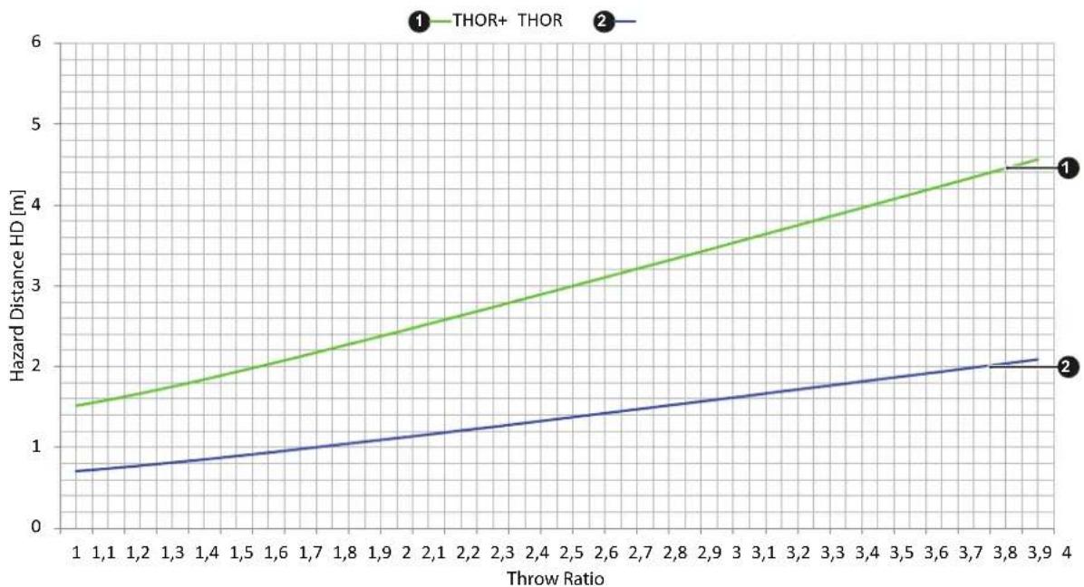
line
| Throw Ratio | THOR+ Hazard Distance HD [m] | THOR | | ----------- | --------------------------- | ---- | | 1 | 1.5 | 0.7 | | 1.1 | 1.6 | 0.8 | | 1.2 | 1.7 | 0.9 | | 1.3 | 1.8 | 1.0 | | 1.4 | 1.9 | 1.1 | | 1.5 | 2.0 | 1.2 | | 1.6 | 2.1 | 1.3 | | 1.7 | 2.2 | 1.4 | | 1.8 | 2.3 | 1.5 | | 1.9 | 2.4 | 1.6 | | 2 | 2.5 | 1.7 | | 2.1 | 2.6 | 1.8 | | 2.2 | 2.7 | 1.9 | | 2.3 | 2.8 | 2.0 | | 2.4 | 2.9 | 2.1 | | 2.5 | 3.0 | 2.2 | | 2.6 | 3.1 | 2.3 | | 2.7 | 3.2 | 2.4 | | 2.8 | 3.3 | 2.5 | | 2.9 | 3.4 | 2.6 | | 3 | 3.5 | 2.7 | | 3.1 | 3.6 | 2.8 | | 3.2 | 3.7 | 2.9 | | 3.3 | 3.8 | 3.0 | | 3.4 | 3.9 | 3.1 | | 3.5 | 4.0 | 3.2 | | 3.6 | 4.1 | 3.3 | | 3.7 | 4.2 | 3.4 | | 3.8 | 4.3 | 3.5 | | 3.9 | 4.4 | 3.6 | | 4 | 4.5 | 3.7 |Image 2-4
System overview
3
About this chapter
This chapter briefly describes all different components of the complete projection system based on the Thor. For more detailed information related to the projector we refer to other chapters in this document. For the other components in the system we refer to its own documentation set of the component. Note that the latest version of this document and all other related documentation sets are available on the Barco website.
Different components of the projection system.
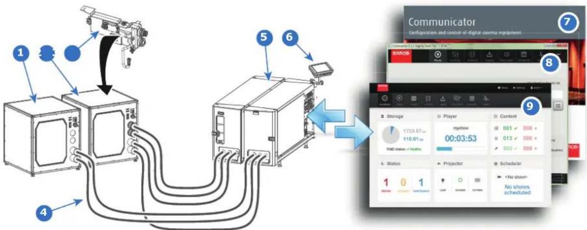
flowchart
graph TD
    A["1"] --> B["2"]
    B --> C["3"]
    C --> D["4"]
    D --> E["5"]
    E --> F["6"]
    F --> G["7"]
    G --> H["8"]
    H --> I["9"]
    I --> J["Storage"]
    I --> K["Player"]
    I --> L["Content"]
    J --> M["mybrow 1723.57 m 110.01 m"]
    K --> N["00:03:53"]
    L --> O["001 000"]
    L --> P["013 000"]
    L --> Q["000 000"]
    M --> R["R&D status"]
    N --> S["Projector"]
    O --> T["Scheduler"]
    P --> U["No shows scheduled"]
    Q --> V["No shows scheduled"]
Image 3-1
1 Chiller unit without expansion for DMD cooling (not used for Thor).
2 Chiller unit equipped with expansion for DMD cooling.
3 Chiller cooling circuit expansion for DMD cooling.
4 Hoses.
5 Projector (with or without external safety interlocks).
Overview
Thor
• Chillers and hoses
- Safety system
• Communicator Touch Panel
• Communicator PC version
6 Touch Panel (optional).
7 Communicator (PC).
8 Commander (ICMP).
9 Web Commander (ICMP).
System overview
• Commander & Web Commander
3.1 Thor
Introduction
The Thor series projector is a RGB laser-illuminated projector. This high-brightness laser projector is capable of showing 4K content at 60 fps and 3D movies in full 4K resolution. The Thor series projector has an integrated color 3D system, with 6-Primary (6P) color laser modules. This Barco Laser3D system maximizes 3D efficiency from a single projector, delivering constant and uniform images in excellent contrast, without lamp flicker.
For functionality and reliability, the projector requires accurate temperature control and cooling below ambient. Therefore a liquid cooling system is provided consisting of liquid circuits inside the projector which are connected via hoses to external chillers. Only chiller models and hoses exclusively developed for this application and approved by Barco are allowed to be used. Barco approved chillers models are listed on the Barco website.
Depending on the projector model one or two chillers are required!
Convention projector orientation
This manual refers to the left side of the projector as the side at your left hand when standing behind the projector and looking at the projection screen in front of the projector.
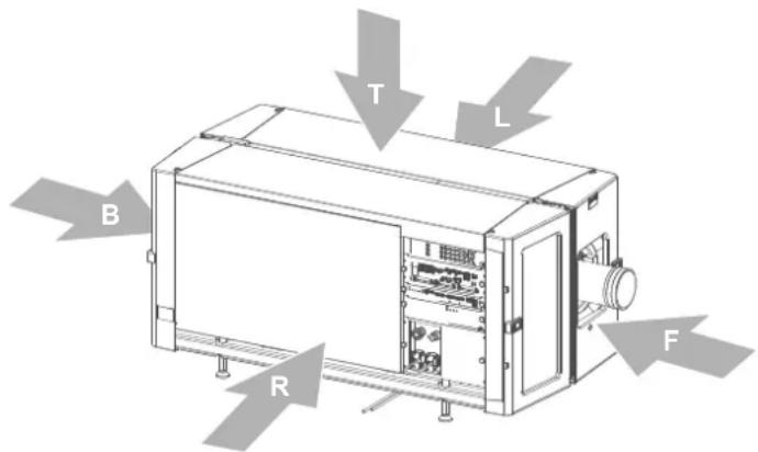
Image 3-2
T Top of the projector.
L Left side of the projector (Light Processor side).
F Front of the projector.
R Right side of the projector (Input side).
B Back side of the projector.
Component location
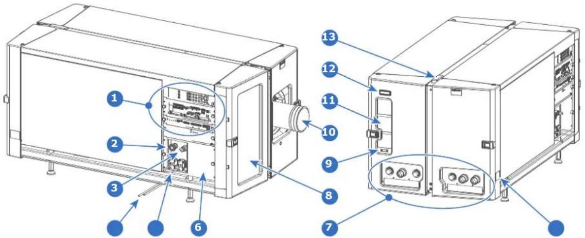
Image 3-3
1 Input & Communication interface.
2 Beam stop button.
3 Beam enable key.
4 Condensed water drain tubes.
5 UPS sockets.
6 Cover mains compartment.
7 Valve coupling to connect with external chiller(s).
8 Air inlet filter.
9 Communication port with chillers.
10 Lens.
11 Air outlet.
12 Projector status light.
13 Laser status light.
14 Projector ID label.
Air flow
The Thor series projector has two air flow channels (reference A & B) to cool the projector electronics. The air intake is at the front side of the projector, the air outlet is at the back side.
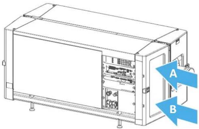
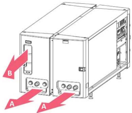
Image 3-4
3.2 Chillers and hoses

DMD
A digital micromirror device, or DMD, is an optical semiconductor that is the core of DLP projection technology.
Introduction
The chillers are specially designed for the Thor series projector. The chillers are controlled by the projector and ensure that the ambient temperature of the lasers and DMDs is within specs. Without these chillers the projector will not operate.
Depending on the projector model one or two chillers are required! For the Thor series projector one chiller has to be installed. The Thor+ series needs two chillers.
One chiller must be equipped with a cooling circuit expansion unit to cool the DMDs. This chiller can be recognized by the extra coupling for the hoses at the front (reference 1 Image 3-5). The expansion unit has to be installed on site.
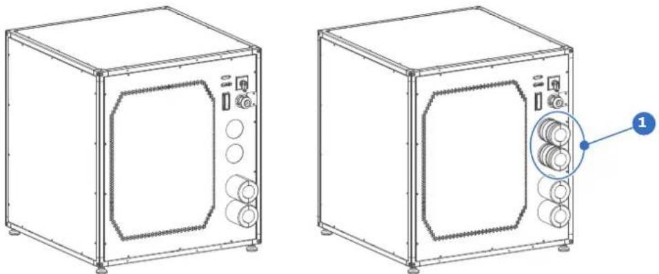
Image 3-5

For installation instructions see documentation of the chiller. All latest documentation files are available on the Barco website. How to connect the chiller(s) with the projector is described in this document.
Chiller cooling circuit expansion for DMD cooling
The valve coupling of this expansion unit is of the same type and size as the standard installed coupling on the chiller. However, the hoses of the DMD cooling which have to be connect with the coupling of this expansion unit has a smaller diameter than the hoses for the Red, Green and Blue laser cooling. Note that the cooling circuit expansion unit for the DMD cooling has to be installed on site.
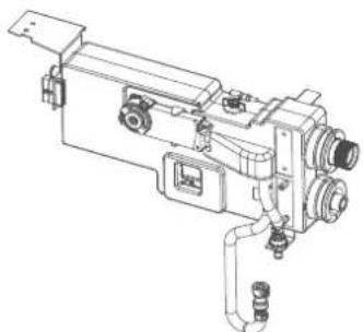
natural_image
Technical line drawing of a mechanical device with multiple ports and mounting brackets (no text or symbols)Image 3-6
The chiller cooling circuit expansion for DMD cooling may only be installed by trained technicians. Installation instructions are included in the service documentation of the chiller.
Hoses
Only hoses specified by Barco can be used to couple the cooling liquid of the chiller with the cooling circuit of the projector. The hoses specified are specially designed for this purpose. Using other hoses than those will have impact on the cooling capacity of the system and may make the system fail!
The hoses are available in different lengths up to 10 meter which is also the maximum distance allowed between chiller and projector. The chiller side of the hose has a straight coupling, the projector side has a 90 degree tube elbow with coupling. The flow direction at the coupling is always from female towards male. The hoses are isolated and reinforced for optimal performance.
The hoses for the RED, GREEN and BLUE laser cluster cooling have a larger diameter size than the hoses for the DMD cooling. However, take into account that the couplings are of the same type and size. So, ensure to connect the right hose with the right cooling channel.
See Barco website for available kits of hoses and corresponding ordering information.
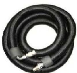
natural_image
Coiled black rubber hose with metallic connectors (no text or symbols visible)Image 3-7: Hose with 90° angle female coupling.
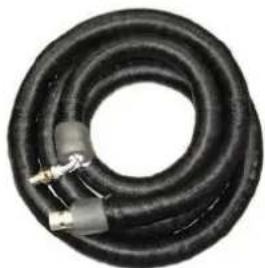
natural_image
Coiled black rubber hose with two connectors (no text or symbols visible)Image 3-8: Hose with 90° angle male coupling.

For chillers and hoses ordering information see Barco website.
3.3 Safety system
Safety controller
The projector is equipped with a safety controller which is located inside the mains compartment. This safety controller operates independent from the projector electronics and has its own power supply. The safety controller is connected with the beam stop button (reference 1 Image 3-9) and the beam enable key (reference 2 Image 3-9) of the projector. In case the beam stop button is pushed or the beam enable key is switched off the safety controller immediately triggers the relay to disconnect the power from all Power Supply Units (PSU) of the lasers.
Beam enable key
The beam enable key (reference 2 Image 3-9) must be in the "on" position to be able to activate the lasers. In case the safety controller is triggered by an interlock event (internal or external) then, after restoring the interlock, the beam enable key must be switched off and on to reset the safety controller. Otherwise, the laser can not be activated.
External beam enable key
The beam enable key is built-in but there is also a connection available for an additional, external switch which is connected in series with the internal beam enable key. This means that both keys must be switched on to power the PSUs of the lasers.
Beam stop button
The beam stop button (reference 1 Image 3-9) is easy accessible by the operator. Pushing the beam stop button will result in disconnecting the power from all Power Supply Units (PSU) of the lasers. The beam stop button requires a quarter turn to restore its normal operating position. After restoring the beam stop button the beam enable key must be switched off and on to reset the safety controller.
External safety interlocks
Two external safety interlocks can be connected with the safety controller (e.g. to connect an infrared field scanning device for the restricted HD area). In case an external safety interlock switch opens the safety controller immediately opens relays to disconnect the power from all Power Supply Units (PSU) of the lasers.
The safety controller requires per interlock a double pole switch. It is not sufficient to break only one of the two interconnections. Both contacts should be opened and closed simultaneously. If only one contact is opened without the second one, the projector will not start up again after the contact is closed. To recover from such an error, open and close the external interlock with both contacts simultaneously, then turn the beam enable key off and on.
Both switch inputs should not be electrically interconnected in any way. An electrical connection between the switches will be seen as an interlock open situation.
The connector (reference 3 Image 3-9) for the external interlocks can be found behind the mains input compartment door. It is in the form of a 10 pole screw type removable terminal block (reference 5 Image 3-9). There are three cable glands (reference 4 Image 3-9) at the base of the mains compartment for the cabling of the external interlock devices.
The projector is shipped with a connector of which the external beam enable key and the 2 external interlocks are bypassed. Before connecting an external interlock the appropriate shunt wires (reference 6 Image 3-9) should be removed and replaced by the interlock wiring.
Component location
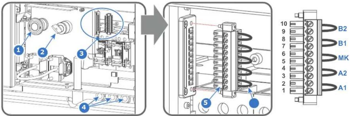
Image 3-9
1 Beam stop button.
2 Beam enable key.
3 Socket and connector for external safety interlocks.
4 Three cable glands (M20 D7-13).
5 10 pins connector.
6 Shunt wire.
A1 External safety interlock A contact No 1.
A2 External safety interlock A contact No 2.
MK External beam enable key.
B1 External safety interlock B contact No 1.
B2 External safety interlock B contact No 2.

CAUTION: The need for installing external safety interlocks is the responsibility of the Safety Officer and depends on the installed application and local regulations.

WARNING: The connector with shunt wires is delivered with the projector but not installed. The Safety Officer of the boot area must decide either if the connector with shunt wires can be installed or if external safety interlocks must be installed.

The external safety interlocks used must be of the type 'micro load' and must be approved interlocks for safety applications. In order to achieve the highest reliability level of safety; employ only SIL level 4 (according IEC 62061) dual normal open contact or performance level Ple (according IEC 13849-1) dual normal open contact devices.
3.4 Communicator Touch Panel
Communicator Touch Panel for digital cinema projectors
The Communicator Touch Panel is designed for multi-user command and control. The Communicator enables users to learn quickly and operate efficiently - using an elegant and flexible Touch Panel interface. The interface's commonality means that operators can intuitively use any model in the product line, without restriction, and its user-friendly nature translates directly into a short and enjoyable learning curve.
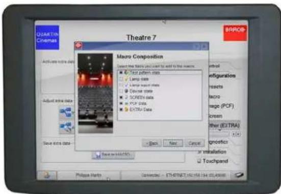
Image 3-10
Flexible Touch Panel interface
The Touch Panel interface can be mounted upon a swivel arm which easily fits on top of the Thor series. One central locking mechanism of the swivel arm allows instant fixation of the Touch Panel interface in any position.
The Touch Panel interface can also be installed further away from the Thor series. For this purpose an Ethernet cable up to 50 meter can be used to realize a direct data communication between the Thor series and the Communicator Touch Panel.
The Touch Panel interface can also be connected via a Local Area Network (LAN) in the same way as the Thor series. In this configuration both devices can communicate with each other as well.
The Touch Panel interface requires a voltage supply +12 VDC and 1,5 ampere. Note that the Thor series has a 12 VDC output which can be used to power up the Touch Panel interface. Nevertheless, the use of a separate +12 VDC adaptor (1,5 ampere minimum) is required in case the Touch Panel interface is installed more then a few meters away from the Thor series.
Parts location of the Touch Panel interface
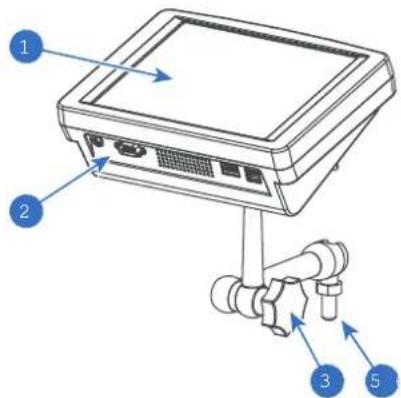
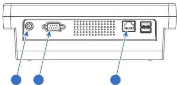
Image 3-11
1 Touch screen
2 Communication panel
3 Knob to operate central swivel clamp
4 Base of swivel arm
5 Power input 12 VDC, 1.5A
6 RS232 port (sub-D)
7 Ethernet port (RJ45)
Touch Panel power/data customized cable
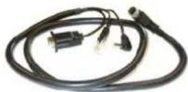
Image 3-12: Customized cable to connect Touch Panel interface with the Barco projector.

The Communicator Touch Panel has its own user guide which latest version is available on the Barco website.
3.5 Communicator PC version
Configuration tool
A uniquely powerful and easy to use configuration tool for the Barco cinema projector. This Communicator software for PC provides all the necessary tools and only those tool necessary for the connected projector to setup and control this projector. A comprehensive array of easy to access menu pages provide the projectors digital input, output and screen display via a combination of simple buttons and displays.
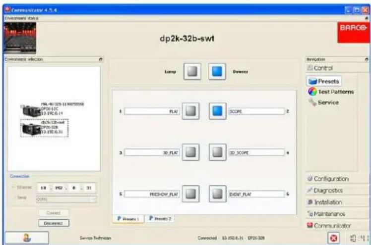
Image 3-13
Quick and Easy configuration
Clearly indicated tab pages allow the control of Projector connection, configuration, test, color calibration and configuration with an existing automation system. All actions can be activated by a simple click. Depending on the user level, functions are enabled or disabled in the software. The enabled functions are only accessible via a password entry and that prevents misalignment once everything is correctly aligned.

The Communicator PC version has its own user guide which latest version is available on the Barco website.
3.6 Commander & Web Commander
Commander
All Barco Alchemy projectors come with the 'Barco Commander' software that runs from a touch panel controller or PC.
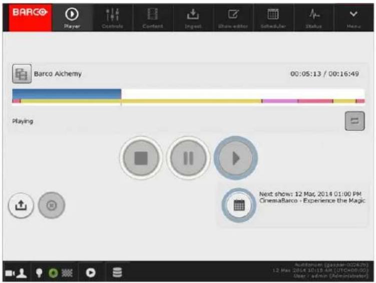
Image 3-14
Web Commander
All Barco Alchemy projectors come with the 'Barco Web Commander' screen management system featuring an intuitive user interface for simple operation.
The Barco Alchemy projectors have been carefully designed to greatly increase the level of operational efficiency. Projectionists can now enjoy a streamlined and intuitive user interface that seamless blends projector control with a full-fledged screen management system. The 'Barco Web Commander' user interface is readily available on the projector without any additional software installation. It is accessed via a web browser and is also fully supported on iOS and Android tablets.
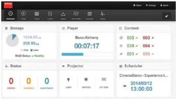
Image 3-15

The Commander and Web Commander have their own user guide which latest version is available on the Barco website.
Getting started 4
About this chapter
Read this chapter before installing your Thor series projector. It contains important information concerning installation requirements for the Thor series projector, such as minimum and maximum allowed ambient temperature, humidity conditions, required safety area around the installed projector, required power net, etc.
Furthermore, careful consideration of things such as image size, ambient light level, projector placement and type of screen to use are critical to the optimum use of the projection system.

Barco provides a guarantee relating to perfect manufacturing as part of the legally stipulated terms of guarantee. Observing the specification mentioned in this chapter is critical for projector performance. Neglecting this can result in loss of warranty.
Overview
• Installation requirements
• Unpacking the projector
- Initial inspection
4.1 Installation requirements
Environment conditions
Table below summarizes the physical environment in which the Thor series projector may be safely operated or stored.
| Environment | Operating Non-Operating | |
| Ambient Temperature | 10°C (50°F) to 30°C (86°F) -15°C (5°F) to 60°C (140°F) | |
| Air cleanliness Clean office environment (equivalent with cleanroom standard ISO 14644-1 ISO Class 9) | n.a. | |
| Humidity 0% RH to 80% RH non-condensed 5% to 95% RH Non-Condensed | -Condensed | |
| Altitude -60 m (-197 Ft) | to 3000 m (9843 Ft)Automatic decrease of brightness possible for altitudes above 1000 m . | -60 m (-197 Ft) to 10 000 m (3 2810 Ft) |

Let the projector acclimatize after unpacking. Neglecting this may result in a startup failure of the Light Processor Unit.
Measures to resolve radio interference
Operation of this equipment in a residential area may cause radio interference. Possible interference shall be solved by one of the following non-limitative product installation measures:
- Create more separation distance between projector and interfered device.
- Change direction of the interfered device.
• Electromagnetic shielding of the projection booth.

No interference to radio communication in neighbor buildings possible if a separation distance of 30 m (32.8 yards) is provided.
Cooling requirements
For functionality and reliability, the projector requires accurate temperature control and cooling below ambient. Therefore a liquid cooling system is provided consisting of liquid circuits inside the projector which are connected via hoses to external chillers. Only chiller models and hoses exclusively developed for this application and approved by Barco are allowed to be used. Barco approved chillers models are listed on the Barco website.
The chiller must be installed in the same environmental conditions as the projector (ambient temperature and humidity must be the same on both projector and chiller locations). The chiller must be installed in upright position (not tilted) conform all the installation instructions of the chiller. Maximum 3 meter height differences is allowed between projector coupling and chiller coupling.
Sensors measure the temperature and relative humidity (RH) inside the sealed compartments of the projector. From these measured values the dew point is calculated and compared with the temperature of the liquid cooling in the chiller.
The dew point inside the sealed compartments of the projector must be lower than the temperature of the cooling liquid coming from the chiller. If not, the projector will fail to startup. This to prevent drops of moisture deposit on the electronic boards.
In case the projector fails to startup due to a dew point inside the projector that is too high, the projector and chiller need more time to acclimatize to the environment. For a first install the time needed to acclimatize depends on the environmental storage conditions of the projector and chiller. In extreme conditions the acclimatization time may take several hours.
Note that the lower the relative humidity of the boot area the shorter the acclimatization time needed for the projector and chiller.
The electronics of the projector are fan cooled. For that the projector must be installed with sufficient space around the projector, minimum 20 cm (8 inch) to ensure sufficient air flow. It should be used in an area where the ambient temperature, as measured at the projector air inlet, does not exceed 30^ C ( 86^ F).
Projection rooms must be well ventilated or cooled in order to avoid build up of heat. It is necessary to vent I exhaust air from projector and cooling system (chiller unit) to the outside of the building. The minimum flow rate of the air extraction system depends on the ambient temperature:
Thor+
| Ambient temperature Minimum airflow per system | |||
| 30°C (86°F) | 370 l/s | (790 CFM) | |
| 25°C (77°F) | 280 l/s | (590 CFM) | |
| 20°C (68°F) | 225 l/s | (475 CFM) | |
Thor
| Ambient temperature Minimum airflow per system | ||||
| 30°C | (86°F) | 280 l/s | (590 CFM) | |
| 25°C | (77°F) | 210 l/s | (440 CFM) | |
| 20°C | (68°F) | 166 l/s | (350 CFM) | |
Where two projectors or more are installed close to each other, ensure that the projectors do not thermally affect each other.
Dew point

The dew point is the saturation temperature for water in air. The dew point is associated with relative humidity. A high relative humidity implies that the dew point is closer to the current air temperature. Relative humidity of 100% indicates the dew point is equal to the current temperature and that the air is maximally saturated with water. When the moisture content remains constant and temperature increases, relative humidity decreases.
Condensed water drain requirements
The projector is equipped with air dryers to remove moisture from the sealed compartments. The condensed water collected by the air dryers is removed from the projector through small drain tubes at the bottom of the projector. It's most efficient and recommended to guide the small drain tubes directly to a water drain.
- A vertical air gap fitting must be installed between the small drain tubes and the building drain! Note that the end of the small drain tubes must be in free air (not airtight taped off) to prevent back flow.
- The minimum downwards slope over the whole length of the small drain tubes is 15 cm per meter (1.8 inch per foot). It's recommended to guide the small drain tubes vertically for optimal flow. Clogging is often the result of improper slope (sloping uphill).
- The maximum allowed length of the small drain tubes (∅8 mm) before ending into the water drain is 2.5 meter (8 feet).
- If no water drain is available then an 'open' water container can be installed to capture the condensed water coming out of the small drain tubes. The volume of the water container depends on the humidity level of the operation environment. In most applications a water container with a volume of 5 liter should be sufficient if emptied regularly.
Main Power requirements
The Thor series projector operates from a nominal 3W+N+PE or 3W+PE power net. The projector must be switched internally between a star connection to a delta connection or vice versa. See installation instructions.
• Electrical ratings for Star system (3W+N+PE):
- The cross-sectional area of the conductors in the power supply cord shall ^2 de 6mm ^2 , 10AWG to 8AWG.
- The electrical rating of the Thor+ projector is 200-240V/346-415V 3W+N+PE 16A 50-60Hz (Y connection) (Y connection).
- The electrical rating of the Thor projector is 200-240V/346-415V 3W+N+PE 10A 50-60Hz (Y connection) (Y connection).
- The building installation has to be provided with a circuit breaker of range 25A to 40A to protect the complete unit.
• Electrical ratings for Delta system (3W+PE):
- The cross-sectional area of the conductors in the power supply cord shall be8AWG.
- The electrical rating of the Thor+ projector is 200-240V 3W+PE 28A 50-60Hz (Δ connection) (Δ connection).
- The electrical rating of the Thor projector is 200-240V 3W+PE 15A 50-60Hz (Δ connection) (Δ connection).
- The building installation has to be provided with a circuit breaker of 40A to protect the complete unit.
The power cord required to connect the projector with the power net is not delivered with the projector. It is the responsibility of the customer to provide the correct type of power cord. Take into account that the cable gland allows a cable diameter from 11 to 21 mm.
To protect operating personnel, the National Electrical Manufacturers Association (NEMA) recommends that the instrument panel and cabinet be grounded. In no event shall this projector be operated without an adequate cabinet ground connection.
The AC supply must be installed by a qualified electrician in conformance to local codes. Hardware, wire sizes and conduit types must comply with local codes.
A readily accessible disconnect device shall be incorporated externally to the equipment for removal of the power to the equipment mains terminals.

WARNING: Disconnect the power to the unit mains terminals and unplug power cord at UPS inlet for removal of all power from the unit
UPS requirements
The Uninterruptible Power Supply (UPS), also known as a Continuous Power Supply (CPS), must have an output voltage of 200-240V at 50-60Hz and must be capable of delivering an output current of 5,5 amperes. This UPS provides only power for the electronics in the Card Cage.
The connection between the UPS unit and the UPS inlet of the projector must be done with a certified AC power supply cord of minimum 0,75 mm ^2 or 18 AWG and minimum 300V.

CAUTION: The 200–240V power outlet (UPS OUTLET) of the projector may not be used to provide the UPS unit with power! The UPS OUTLET of the projector may only be used for connection to the UPS INLET of the projector.

The Thor series projector does not have a built in UPS unit.
Projection screen
The Thor series projector performs best when the image is projected on white screen with minimum gain (between 1 and 1.8). Very high gain screens (e.g. silver screens with gain 2.4) are not recommended.
Projector weight
Do not underestimate the weight of the Thor series projector. The Thor + projector weight approximately ±240 kg (±529 lbs) without lens. The Thor projector weight approximately ±200 kg (±440 pounds) without lens. Ensure that the pedestal on which the projector is installed is capable of supporting the complete load of the system. To prevent personal injury a hoisting tool should be used to lift the projector.

CAUTION: An external frame must be used to stack projectors.
4.2 Unpacking the projector
What you need to do?
Upon delivery, your projector is packed into a carton box upon a wooden/plastic pallet and secured with banding and fastening clips. Furthermore, to provide protection during transportation, the projector is surrounded by foam. Once the projector has arrived at the installation site, it needs to be removed from its carton box and wooden/plastic pallet in a safe manner without damaging the projector.
Required tools
10 mm Allen wrench.
How to unpack the projector?
- Loosen the banding (reference 1 Image 4-1) by pulling the free end of the banding loop in the clip.
- Take off the box cover (reference 2 Image 4-1).
- Remove the carton plate (reference 3 Image 4-1) from the top of the projector.
- Take out the small box between the outer and inner box. This box contains the product documentation (manuals, etc.).
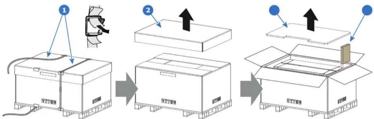
flowchart
graph TD
    A["1: Open box with cable and plastic wrap"] --> B["2: Up arrow on top box"]
    B --> C["3: Box with lid and plastic bag"]
    C --> D["4: Closed box with paper and plastic bag"]
Image 4-1
- Lift up the outer carton box (reference 5 Image 4-2) as a whole and remove it away from the projector package.
- Lift up the inner carton box (reference 6 Image 4-2) as a whole and remove it away from the projector package.
- Remove the screw (reference 7 Image 4-2) in the centre of both transport fixation bars (front and rear of the projector). Use a 10 mm Allen wrench.
- Now the projector can be lifted up and put in place.

Warning: Do not underestimate the weight of the projector. The projector weights ±240 kg (±529 lbs).
To prevent personal injury a hoisting tool should be used to lift the projector.

Note: The top side of the projector is foreseen with four threaded holes M10 (25 mm depth), one in each corner. These holes can be used to insert eyebolts to connect the shackles of the lifting equipment.
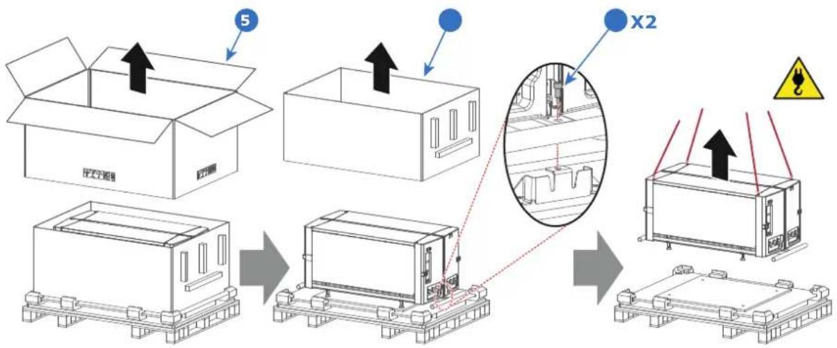
flowchart
graph TD
    A["Open Box"] --> B["Assembly"]
    B --> C{X2}
    C --> D["Final Assembly"]
    style A fill:#f9f,stroke:#333
    style B fill:#ccf,stroke:#333
    style C fill:#cfc,stroke:#333
    style D fill:#fcc,stroke:#333
Image 4-2
! Caution: Ensure that the pedestal is capable to carry the weight of the projector.

After unpacking, allow the projector to acclimatize to a room temperature ranging from 10°C (50°F) to 30°C (86°F) MAX. Neglecting this may result in a start up failure of the Light Processor Unit.
4.3 Initial inspection
General
Before shipment, the projector was inspected and found to be free of mechanical and electrical defects. As soon as the projector is unpacked, inspect for any damage that may have occurred in transit. Save all packing material until the inspection is completed. If damage is found, file claim with carrier immediately. The Barco Sales and Service office should be notified as soon as possible.

The packaging of the Thor series projector is provided with a shock-watch label. If this shock-watch label was triggered (red colored at arrival) during transport may indicate rough handling by the transport company. In this case, the instructions mentioned on the label, should be followed, which are: adding a note on the "bill of lading" and informing the transport company and the Barco sales and service office as soon as possible.
Box content
- Projector.
- User and installation manual (this document).
- Safety manual.

The projector lens is not included in the package of the projector.
Mechanical check
This check should confirm that there are no broken knobs or connectors, that the cabinet and panel surfaces are free of dents and scratches, and that the operating panel is not scratched or cracked. The Barco Sales and Service office should be notified as soon as possible if this is not the case.
Installation process
5
About this chapter
After you have unpacked and checked the projector, you can start with the installation process of your Thor series projector. This chapter gives an overview of all the different stages in the installation process which you have to be followed to set your Thor series projector up and running. Each stage is briefly described and refer to more detailed step by step procedures in this manual.
Use this overview as a checklist to ensure that all stages have been followed in the setup process the Thor series projector.

After unpacking, allow the projector and chiller(s) to acclimatize to a room temperature ranging from 10°C (50°F) to 30°C (86°F) MAX. Neglecting this may result in a start up failure of the Light Processor Unit.
Overview
• Installation process overview
5.1 Installation process overview
Installation process from A to Z
- Check if all installation requirements are fulfilled such as the environment conditions of the installation area, electrical facilities, etc. Note that a solid pedestal is required to support the projector. For more info see topic “Installation requirements”, page 36.
Tip: Barco offers a pedestal for the Thor series series projector. This pedestal allows for a solid and easy setup of the projector and chillers that fit underneath the pedestal.
- Physical installation of the chiller. One chiller has to be installed. Follow precisely the installation instructions delivered with the chiller. Only by Barco approved chillers may be used. Ensure that the distance between the chiller and projector can be bridged with the hoses delivered with the system. Take into account that the height difference between chiller coupling and projector coupling should be less than 3 meter.
Note: The chiller must be equipped with the cooling circuit expansion unit for the projector DMD cooling. See chapter chapter "Chillers and hoses", page 28. This expansion unit has been installed on site. See installation instructions delivered with the chiller.
Note: Ensure to install the correct address plug for the chiller. The chiller which is equipped with the cooling circuit expansion unit has a different address plug installed. See installation instructions delivered with the chiller.
- Physical installation of the projector upon its pedestal. Position the projector correctly on its pedestal and then remove the transport protection bars at the front and at the rear side of the projector. See chapter "Physical installation", page 45.
- Capture condensed water. Guide the small drain tubes at the bottom of the projector directly to a water drain. If no water drain is available then an 'open' water container must be installed to capture the condensed water coming out of the small drain tubes. See chapter "Installation requirements", page 36.
- Installing the hoses and communication cables between chiller and projector. Note that only by Barco approved hoses may be used. See chapter "Connecting the hoses with projector and chillers", page 49, and chapter "Connecting the data cable with projector and chillers", page 51.
- Installing the isolation shells at both ends of the hoses. An accessory kit containing the isolation shells is delivered separately. For precise installation instructions see documentation included in the accessory kit.
- Installing the external safety interlocks if needed. It's up to the Laser Safety Officer to investigate the need of external safety interlocks and to ensure a correct installation of the external safety interlocks when needed. For more info about external safety interlocks see chapter "Safety system", page 30. For installation instructions see chapter "Connecting the external safety interlocks", page 53.
- Power input set up and electrical connection with the mains electricity. First check if the three phase configuration (Y-Δ) of the projector matches with the voltage of the mains electricity. To adapt the configuration see chapter "Three phase power input configuration of the projector", page 54. Then connect the projector with the mains electricity. See chapter "Connecting the projector with the mains electricity", page 55.
- Installation of a suitable UPS unit or bypass the power in and outlet for the projector electronics. See chapters "Connecting a UPS to the projector electronics", page 57 or "Power loop through to the projector electronics", page 56.
- Installation of the Communicator Touch Panel. See chapter "Installing the Communicator Touch Panel", page 58.
- Installation of the lens. First select a lens with appropriate throw ratio covering the screen size and the projector - screen distance. Then install the lens in the lens holder of the projector. For more information about available lenses, lens selection and lens installation see chapter "Lenses & Lens selection", page 61.
Caution: The projector is delivered with a protective cover inside the Lens Holder. Remove the cover prior to installing the lens.
- Installation of the ICMP(-X) or IMB. (only in case no ICMP(-X) or IMB is factory installed).
- Installation of the HDDs. In case the HDDs of the ICMP are delivered separated from the projector remove the protection tape from the HDD input slots and install all three HDDs as described in the procedure
"Installing a HDD into the ICMP(-X)", page 84. Make sure that all HDDs in the ICMP(-X) HDD set have the same storage capacity. See label on top of the HDD to know the storage capacity.
- Acclimatization of the complete system. Let the projector, chillers and hoses acclimatize to the ambient conditions of the projection room. Ensure that all environmental requirements are fulfilled. See chapter "Installation requirements", page 36.
Note: For a first install the time needed to acclimatize depends on the environmental storage conditions of the projector and chillers. In extreme conditions the acclimatization time may take several hours. Note that the lower the relative humidity of the boot area the shorter the acclimatization time needed for the projector and chillers.
- Fence off the HD restriction zone if needed. See chapter "High Brightness precautions: Hazard Distance (HD)", page 20.
- Switch on the chiller. See documentation of the chiller.
- Switch on the projector. The projector can now be switched on. Place the ON/OFF switch of the projector in the "I" position. As a result the projector starts to initialize. The status lights of the projector lights up GREEN once the projector is initialized. In case the status lights up RED may indicate a tamper event during transport. If so, contact Barco customer service.
Note: The projector always boots up in the same mode (E.g. Standby or Operation) as it was switched off. In case the projector starts up in Standby mode, press the Standby button for three seconds to bring the projector in Operation mode. For detailed information about starting up the projector see chapter "Starting up", page 109.
- Select the corresponding lens parameters for the installed lens. See user guide of the "Communicator" chapter Installation > Advanced > Lens parameters.
-
Alignment of the projected image on the screen. The image can be aligned with the screen size of the application. Follow the next steps to achieve that:
-
Press the LIGHT button on the Local Keypad to activate the lasers.
- Press the DOWSER button on the Local Keypad to open the mechanical dowser of the projector. The dowser is open if the color of the DOWSER button is GREEN.
- Press the TEST PATTERN button on the Local Keypad to project one of the internal test patterns of the projector on the screen.
- Perform a "Lens Homing". See user guide of the Communicator.
-
Use the lens ZOOM, SHIFT and FOCUS buttons on the Local Keypad to match the projected image with the screen. Tilt the projector in case you can not SHIFT the image completely upon the screen. See "Positioning the projector at port window", page 46 See chapter "Local Keypad", page 72, for detailed description of the Local Keypad buttons.
-
Adjusting the light path. Normally the convergence and Scheimpflug of the projector are perfectly adjusted at the factory. Nevertheless, some applications require a readjustment of the lens holder, convergence or both. See procedure “Scheimpflug”, page 115 and “Convergence”, page 127.
- Calibration of luminance, white point and color gamut. See chapter "Calibration", page 135.
- SCC calibration.
Note: A Spatial Color Calibration (SCC) has to be execute in case of a first install or in case a High Brightness lens is swapped with a High Contrast lens or vice versa. See user guide of the Communicator for detail SCC calibration instructions.
- Creating screen files, lens files, light sensor calibration (LSC) files, and macro files for FLAT and for SCOPE. See user guide of the Communicator.
- Backup of all projector configuration files. See user guide of the Communicator.
- Registration of the projector. The Thor series projector is DCI compliant and should be registered.
-
Projection of a digital cinema movie.
-
In case the projector is equipped with an ICMP(-X), download the ICMP(-X) device certificate, request KDM and DCP from the content supplier, ingest KDM and DCP, and play out the movie. for detailed instructions see chapter "ICMP(-X)", page 77, and user guide of the Communicator and/or (Web) Commander.
• In case the projector is equipped with an Integrated Media Block (IMB) see user guide of the IMB.
Physical installation
6
About this chapter
This chapter describes how the mechanical and electrical set up of your Thor series projector has to be done.
Overview
• Removing the transport protection bars
• Positioning the projector at port window
• Connecting the hoses with projector and chillers
• Connecting the data cable with projector and chillers
• Accessing the mains compartment
• Connecting the external safety interlocks
• Three phase power input configuration of the projector
• Connecting the projector with the mains electricity
• Power loop through to the projector electronics
• Connecting a UPS to the projector electronics
• Installing the Communicator Touch Panel
6.1 Removing the transport protection bars
What needs to be done?
After the projector is unpacked and placed on its pedestal the transport protection bars at the front and at the rear of the projector have to be removed.

The transport protection bars need to be removed to connect the hoses of the cooling system with the projector and to have easy access to the dust filter at the front side.
Required tools
Allen wrench 10 mm
How to remove the transport protection bars?
- Remove the two fixation screws (reference 1 Image 6-1) in the center of the transport protection bar. Use a 10 mm Allen wrench.
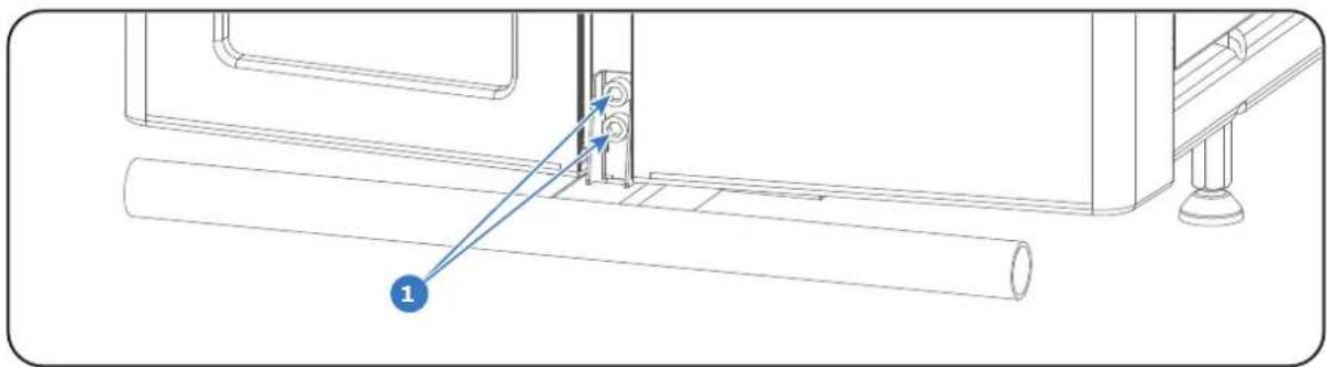
natural_image
Technical line drawing of a mechanical assembly with a cylindrical component and mounting bracket (no text or symbols)Image 6-1
- Pull the transport protection bar out of its slot.
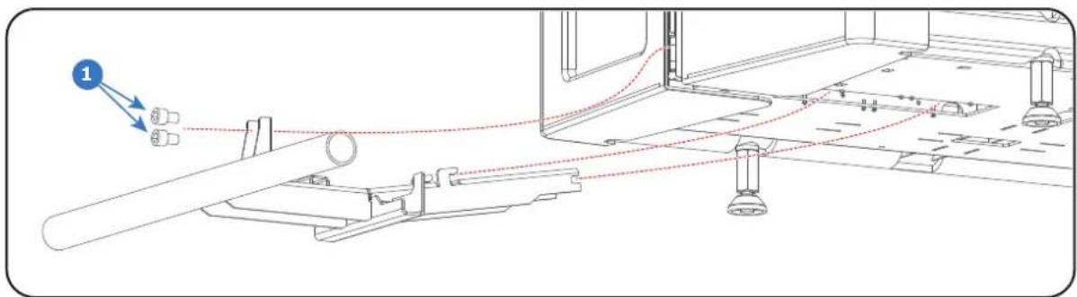
Image 6-2
- Repeat these steps to remove the other transport protection bar as well.
6.2 Positioning the projector at port window
General guidelines
- Use a solid pedestal to mount the Thor series projector on to. Ensure that the pedestal can support the weight of the projector and that all feet of the projector are captured.
- The pedestal should be placed in front of the port window wall in a manner such that the projector lens is at a minimum distance of 20 centimeters from the port window.
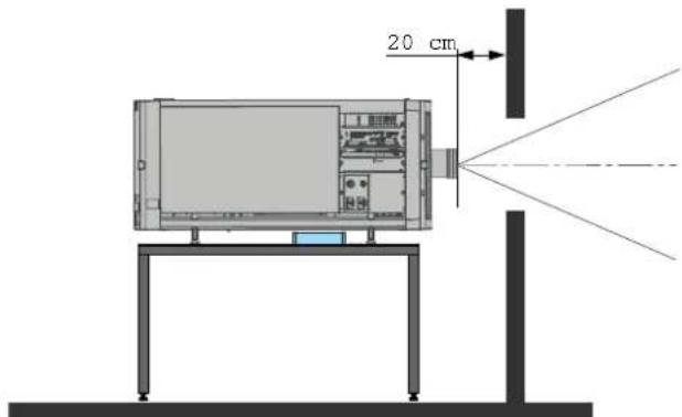
Image 6-3: Positioning at port window

Barco offers a pedestal for the Thor series series projector. This pedestal allows for a solid and easy setup of the projector and chillers that fit underneath the pedestal.
Required tools
• 17 mm open end wrench
• 24 mm open end wrench
Projector centering
- If the projector is standalone in front of the port window, center the projector with the theatre screen (see reference A Image 6-4).
- If another film projector is already present (projector will be off-center), try to optimize aim (see reference B Image 6-4).
Note: Unlike analog film projectors, it is best to keep the projector lens surface as parallel as possible to the screen, even if it is significantly above the screen center.
Note: All feet have an adjustment range of 10 cm. The minimum feet height is 8 cm below the bottom of the projector, the maximum feet height is 18 cm.
The off-center position slightly increases side keystone, but will minimize horizontal lens offset required.
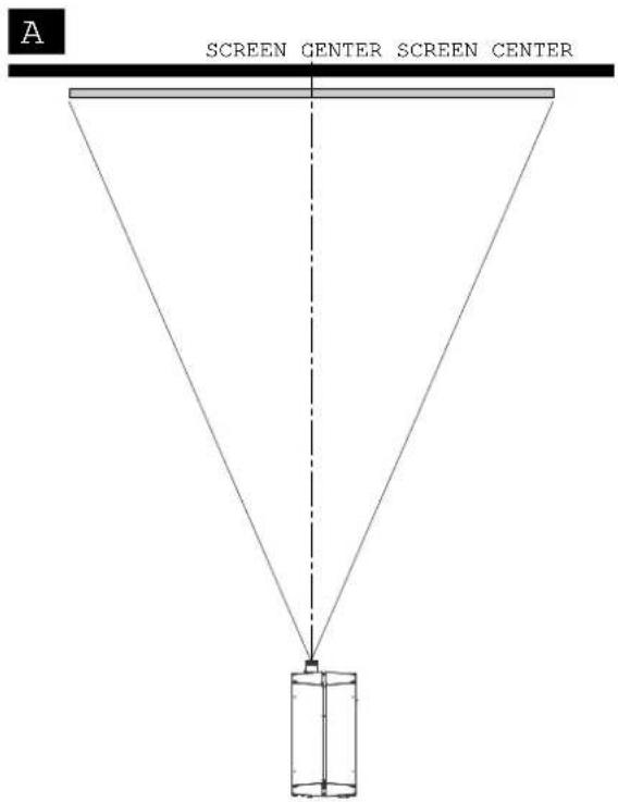
Image 6-4
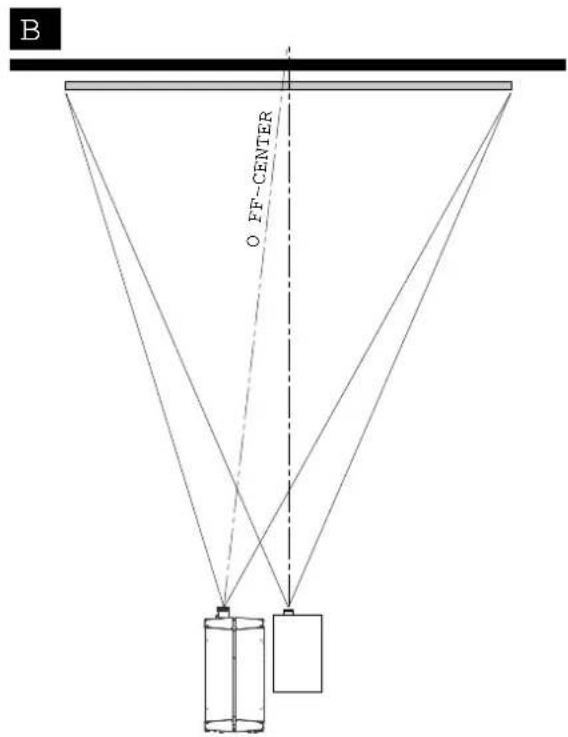
-
Proceed to level the projector by adjusting the feet of the projector as follows:
-
Loosen the long nut (reference 1 Image 6-5) on the threaded rod of the four projector feet. Use a 24 mm open end wrench.
- Adjust the height of the four legs to level the projector. Use a 17 mm open end wrench to adjust the height as illustrated (reference 2 Image 6-5).
- Secure the leg height by tightening the long nuts (reference 1 Image 6-5) of each projector foot against the projector chassis.
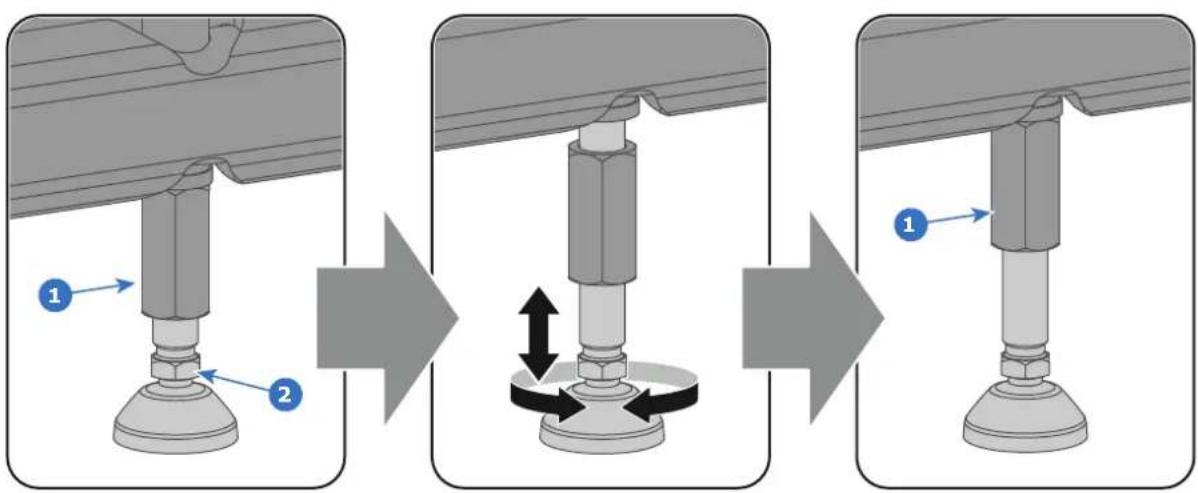
Image 6-5
- Later, when the projector is up-and-running, adjust precise image geometry and placement.
Projector tilting
In an ideal installation, the Thor series projector lens surface is centered with and parallel to the screen. This orientation helps to ensure optimized lens performance with minimal offset. If this position is not possible (such as when the projector is significantly higher than the center of the screen), it is better to rely on offset rather than extra tilt. In other words, use the SHIFT functionality of the Lens Holder prior to tilt the projector.
- Before adjusting tilt, make sure the projector is as well-centered with the theatre screen as possible for the installation area.
- Check the degree of screen tilt, or measure this incline with a protractor at the screen.
-
Tilt the projector to closely match this screen tilt angle as follows:
-
Loosen the nut (reference 1 Image 6-5) on the threaded rod of the four projector feet. Use a 24 mm open end wrench.
- Adjust the height of the four legs until the projected image matches the projection port window and the screen tilt. Use a 17 mm open wrench to adjust the height as illustrated (reference 2 Image 6-5).
- Secure the leg height by tightening the long nuts (reference 1 Image 6-5) of each projector foot.
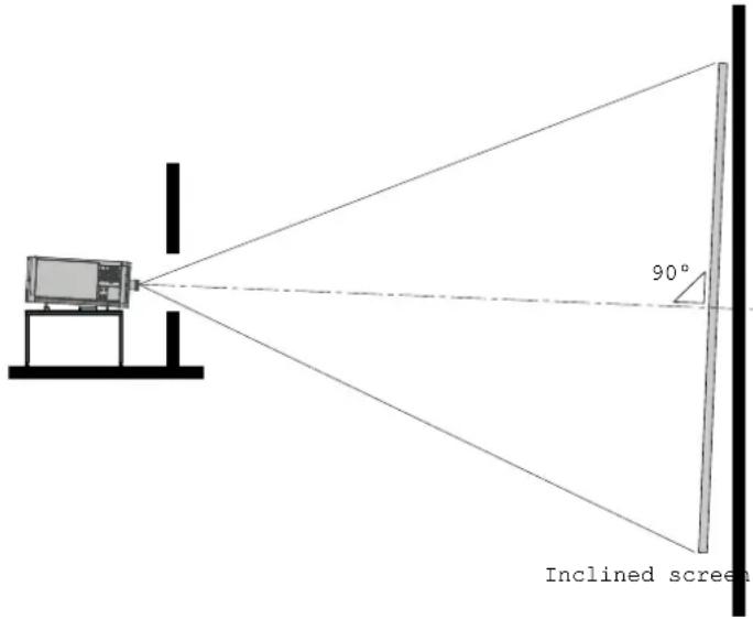
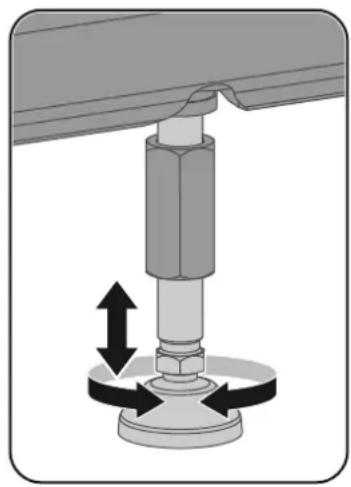
natural_image
Mechanical assembly diagram showing a bolt and nut assembly with directional arrows indicating motion (no text or symbols)Image 6-6

CAUTION: The Thor series may tilt maximum 20^ forward and maximum 5^ backwards. No tilt is allowed sideways.

All feet have an adjustment range of 10 cm. The minimum feet height is 8 cm below the bottom of the projector, the maximum feet height is 18 cm. This correspond with a forward tilt of 6.7^ if the front feet are completely turned in and the back feet turned out.

Barco offers a pedestal for the Thor series projector. This pedestal has height adjustment blocks which allows extra tilt of 3.3°/block (one block has a height of 5 cm). Maximum stack additional blocks four high.
6.3 Connecting the hoses with projector and chillers
What has to be done?
The cooling circuit of the chiller(s) has to be connected with the cooling circuit of the projector. For that hoses are needed. The length of the hoses depend on the position of the chillers in relation to the projector. The maximum length is 10 meter!
Depending on the projector model one or two chillers are required! For the Thor series projector one chiller has to be installed. The Thor+ series needs two chillers.

This procedure assumes that the chiller(s) and projector are already installed. It is also advised to use the Thor series accessory kit and install the support frames before you connect the hoses and use the hose shells after connecting the hoses. See the Accessory kit installation manual for more details.
Hoses IN/OUT connection scheme
The labels on the projector and on the chiller indicating the three different cooling circuits: (R/B, G and DMD) and the direction of the liquid flow: OUT and IN. 'OUT' means liquid flows out of the chiller or projector, 'IN' means liquid flows into the chiller or projector. Both sides of all hoses are also labeled.
| Chiller without DMD cooling unit(not for Thor) | Chiller with DMD cooling unit Projector | |
| DMD OUT DMD IN | ||
| DMD IN DMD OUT | ||
| R/B OUT R/B IN | ||
| G OUT G IN | ||
| G IN G OUT | ||
| R/B IN R/B OUT | ||

The Thor series projector requires only one chiller. The circuits G-IN and G-OUT are omitted.
How to connect the hoses?
- Ensure that all connectors of the hoses, chillers and projector are clean. Wipe away any dust before attaching.
- Connect the hoses one by one with the chiller and projector as illustrated below. (see also 'IN/OUT connection scheme' above)
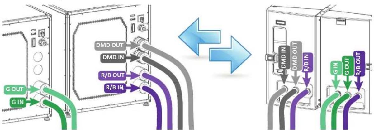
flowchart
graph LR
    A["G IN"] --> B["Gate"]
    C["G OUT"] --> D["Gate"]
    E["DMD OUT"] --> F["Output"]
    G["DMD IN"] --> H["Output"]
    I["R/B OUT"] --> J["Output"]
    K["R/B IN"] --> L["Output"]
    M["DMD IN"] --> N["Output"]
    O["DMD OUT"] --> P["Output"]
    Q["R/B IN"] --> R["Output"]
    S["R/B OUT"] --> T["Output"]
Image 6-7
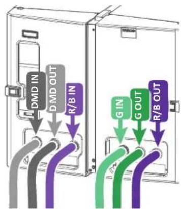
flowchart
graph TD
    A["DMD IN"] --> B["Gray Pipe"]
    C["DMD OUT"] --> D["Purple Pipe"]
    E["R/B IN"] --> F["Purple Pipe"]
    G["G IN"] --> H["Green Pipe"]
    I["G OUT"] --> J["Green Pipe"]
    K["R/B OUT"] --> L["Purple Pipe"]
Note: The circuit is pressurized which makes it sometimes difficult to insert the hoses.
Tip: First move the latch (reference 1 Image 6-8) away from the connection while coupling the hose. Then release the latch and push the hose further until the latch locks.
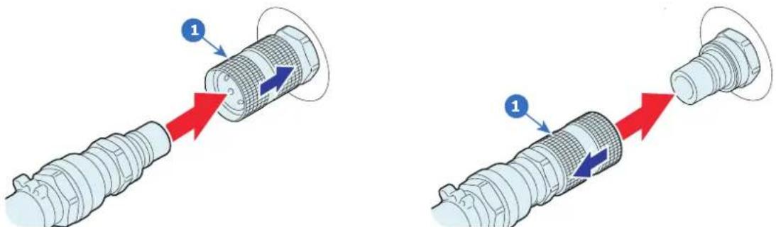
natural_image
Two diagrams showing a mechanical component being inserted into a housing, with arrows indicating direction (no text or symbols present)Image 6-8: Left: Male hose connection, right: Female hose connection

CAUTION: Do not interchange the different cooling circuits with each other! Otherwise the system will fail.

CAUTION: The minimum bend radius of the hoses is 30 centimeter.
6.4 Connecting the data cable with projector and chillers
What has to be done?
Next to connecting the hoses, the communication port of the chillers has to be connected with each other and with the projector.
Depending on the projector model one or two chillers are required! For the Thor series projector one chiller has to be installed. The Thor+ series needs two chillers.
Required parts
• One long (10 meter) communication cable with SUBD Male/Female 15 pins plugs.
- One short (5 meter) communication cable with SUBD Male/Female 15 pins plugs (only if two chillers are required).
How to connect the communication ports of the chillers with the projector?
- Does the system contain two chillers?
▶ If yes, connect the output port of one chiller (reference 1 Image 6-9) with the input port of the other chiller (reference 2 Image 6-9). Use for this a short communication cable.
▶ If no, proceed with the next step.
- Connect the output port of the chiller (reference 3 Image 6-9) with the communication port of the projector (reference 4 Image 6-9). Use for this a long communication cable.

Tip: Guide the long communication cable together with the hoses.
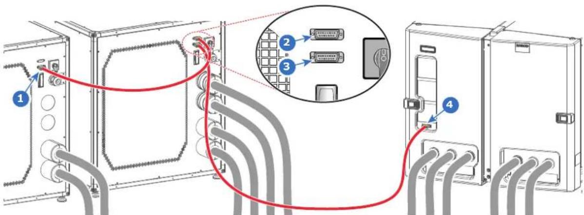
Image 6-9
6.5 Accessing the mains compartment
Required tools
• Phillips screwdriver PH1
• Allen wrench 3 mm
How to access the mains compartment?
-
Loosen the four retaining screws (reference 1 Image 6-10) of the mains cover. Use a PH1 Phillips screwdriver.
-
Remove the mains cover.
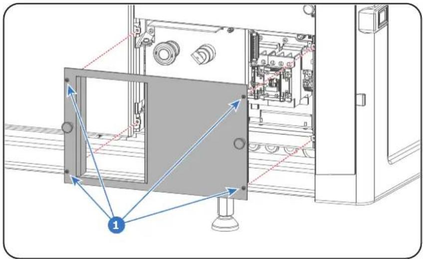
Image 6-10
- Unlatch and pivot the right front plastic cover door (door which contains the dust filters).
- Loosen the retaining screw (reference 2 Image 6-11) of the inner door. Use a PH1 Phillips screwdriver.
- Pivot the inner door to access the mains compartment from the side.
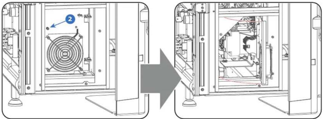
natural_image
Technical line drawing showing a mechanical assembly before and after transformation, with no visible text or symbols.Image 6-11
- Loosen the retaining screw (reference 3 Image 6-12) of the inner front door (door with the Stop button). Use a 3 mm Allen wrench.
- Pivot the inner front door to have full access the mains compartment parts.
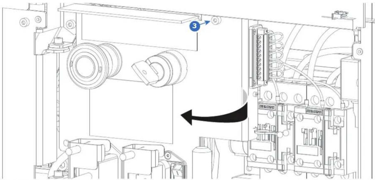
Image 6-12
6.6 Connecting the external safety interlocks

The terminal for the external safety interlocks is located inside the mains compartment. This procedure assumes that the cover of the mains compartment is already removed. See chapter "Accessing the mains compartment", page 51.
Required tools
Flat screwdriver (small)
How to connect the external safety interlocks with the projector?
- Remove the 10 pole terminal block from its socket (reference 3 Image 6-13). Use a small screw driver.
- Guide the cable(s) coming from the external interlock device(s) through the cable gland(s) located at the base of the mains compartment (reference 4 Image 6-13).
- Remove the shunt wire(s) from the 10 pole terminal block and connect the cable(s) according to the schematic in Image 6-13.

Note: Only remove the shunt wires from these pins which have to be connected with an external safety interlock device. All other shunt wires must remain in place.

Note: Maximum two external safety interlock devices can be connected. These interlock devices must have double pole normal open contacts. So, for normal operation of the projector the normal open contacts are pushed into the closed state to close the circuit and thus enabling the activation of the PSU of the lasers.
The internal master key can be extended with a single pole external master key (MK).
- Insert the 10 pole terminal block back in its socket. Use a small screw driver to fixate the terminal block.
- Insert the cable(s) in the cable tie located below the terminal block (reference 5 Image 6-13).
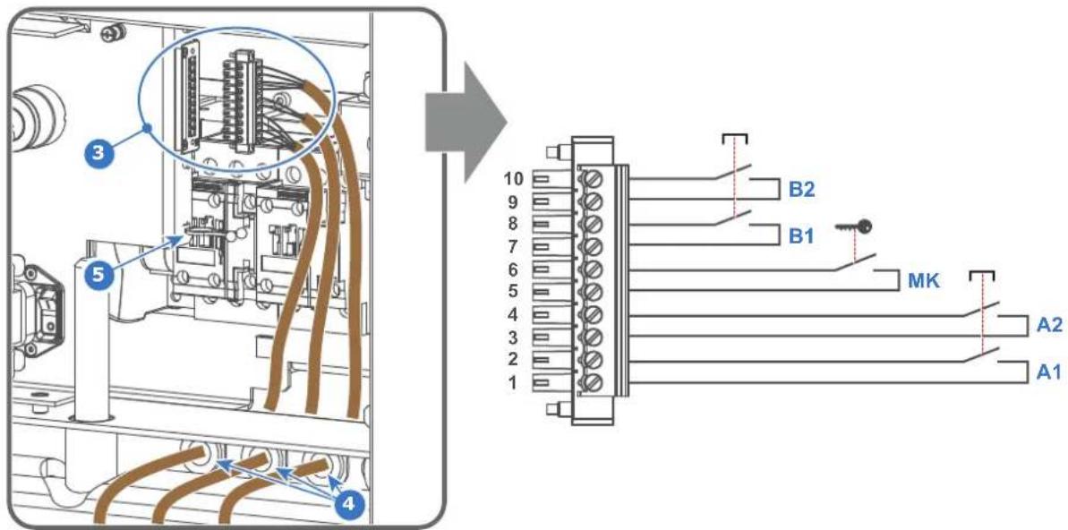
Image 6-13
- Install the cover of the mains compartment.
6.7 Three phase power input configuration of the projector
About the power input
The projector power input can be configured for a power supply of 200-240V / 346-415V in a Y configuration (3W+N+PE) or for 200-240V in a configuration (3W+PE). Before operating the projector, place the links in the correct position depending on the local power supply.
For a 3W+N+PE system, 346-415V is measured between the lines, 200-240V is measured between the lines and the neutral.
For a 3W+PE system, 200-240V is measured between the lines.
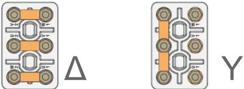
Image 6-14: Y/Δ configuration block (left: delta, right: star)

WARNING: Ensure that the mains is disconnected from the projector prior to start with this procedure.

The Y/Δ configuration block is located inside the mains compartment. This procedure assumes that the cover of the mains compartment is already removed. See chapter "Accessing the mains compartment", page 51.
Required tools
- Nut driver 10 mm
- Torque wrench with 10 mm hexagon socket
How to switch from a Y-connection to -connection
- Loosen the 6 top nuts on the Y/Δ configuration block. (1 to 6)
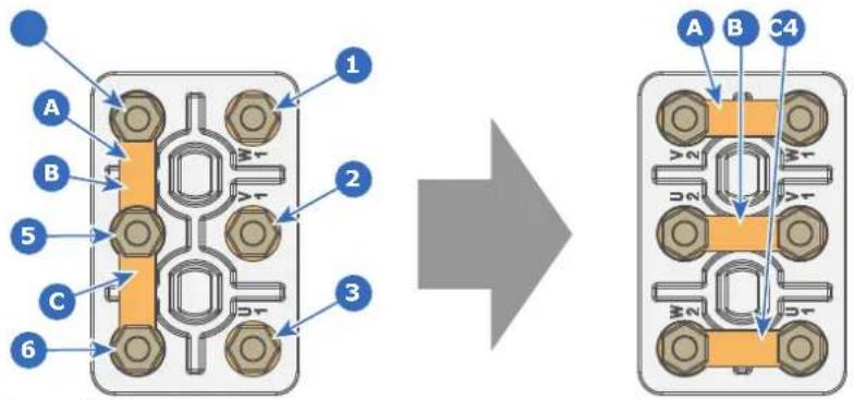
Image 6-15
- Take off the mounted links (A, B and C). Two links above each other or mounted between the upper and middle pin (A, B) and one link between the middle pin and lower pin (C).
- Mount the links horizontally on the pins.
- Turn a nut on each pin and secure with a torque wrench set to 7.5 Nm.
How to switch from a -connection to Y-connection
- Loosen the top nuts on the Y/Δ configuration block (1 to 6).
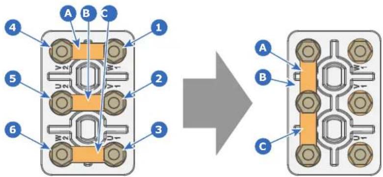
Image 6-16
- Take off the mounted links (A, B and C).
- Connect the left pins together. Place 2 links between the upper pin and the middle pin (A, B) and 1 link between the middle pin and the lower pin (C).
6.8 Connecting the projector with the mains electricity

WARNING: The total electrical installation should be protected by an appropriate rated and readily accessible disconnect switch, circuit breakers and ground fault current interrupters. The installation shall be done according to the local electrical installation codes.

CAUTION: The cross-sectional area of the conductors in the AC power supply cord shall be not less than 4m ^2 to 6mm ^2 , 10AWG to 8AWG in case of a star (Y) configuration and not less then 6mm ^2 , 8AWG in case of a delta (Δ) configuration.
Required tools
• Flat screw driver 4 x 100 mm
- Torque wrench with flat-head socket (medium size)
Required parts
Certified AC power supply cord, min. 500V. Take into account that the cable gland of the projector allows a cable diameter from 11 to 21 mm.
How to connect the projector with the mains electricity?
- Remove the cover of the mains compartment. See procedure "Accessing the mains compartment", page 51.
- Push the stripped AC power supply cord through the cable gland (reference 2 Image 6-17).
- Connect the wires to the 5-terminal strip (reference 1 Image 6-17) as illustrated. Use a torque screw driver to fasten the screws of the 5-terminal strip with a torque of 1.7Nm (1.25 lbf*ft).
Always connect the ground wire (PE) with the connector indicated with PE on the terminal barrier strip. If a neutral conductor is available, connect always to the connector indicated with N on the terminal barrier strip.
Warning: Connect first the PE wire, then the other wires.
Caution: When using a flexible AC power supply cord, make sure that each conductor end is provided with an end sleeve.
Tip: Check for good fixation by pulling on each wire.
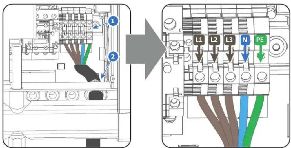
Image 6-17
- Secure the AC power supply cord by fastening the cable gland (reference 2 Image 6-17).
- Install the cover of the mains compartment.
6.9 Power loop through to the projector electronic

This procedure explains how to provide the projector electronics with power in case no UPS unit is used. Note that the projector is by default configured for use without UPS. So, the short power link cable is already installed.
Required tools
No tools required.
Required parts
Short power link cable with plug type C13/C14
How to loop through the power?
- Plug in the short power cable (reference 1 Image 6-18) which was delivered with the projector.

Warning: Always use the Barco short power cable which is delivered with the projector.
-
Secure both plugs of the short cable with a fixation spring (reference 2 Image 6-18). Handle as follow:
-
Squeeze the fixation spring together.
- Slide the fixation spring on the fixation pins (reference 3 Image 6-18) while squeezing together and push it against the power plug.
- Release the fixation spring.
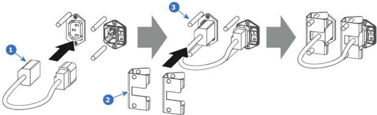
flowchart
graph TD
    A["1: Plug-in plug-in cable"] --> B["2: Plug-in connector"]
    B --> C["3: Wiring socket with plug-in cable"]
    C --> D["End: Terminal terminal connection"]
Image 6-18
6.10 Connecting a UPS to the projector electronics

WARNING: Only use UPS units which are suitable for the Thor series series projector. See chapter "Installation requirements" for more information about the requirements of the UPS.
Required tools
No tools required.
How to connect the UPS
- Install the UPS according to the instructions of the manufacturer and the local regulations.
- Connect the power output cord from the UPS unit to the UPS inlet socket of the projector (right socket).
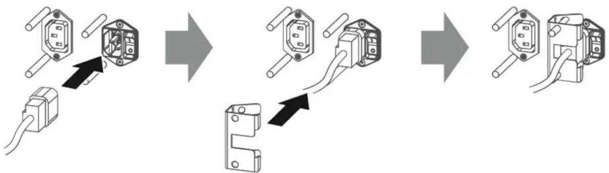
flowchart
graph LR
    A["Switch with cable"] --> B["Switch with cable connector"]
    B --> C["Switch with cable connector"]
    C --> D["Switch with cable connector"]
    D --> E["Switch with cable connector"]
Image 6-19
-
Secure the UPS inlet socket with a fixation spring. Handle as follow:
-
Squeeze the fixation spring together.
- Slide the fixation spring on the fixation pins while squeezing together and push it against the power plug.
-
Release the fixation spring.
-
Install on the power outlet the second fixation spring to prevent losing it.
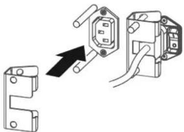
natural_image
Diagram showing a hand inserting a socket into an electrical outlet, with no text or symbols present.Image 6-20

CAUTION: The electrical connection with the UPS INLET socket of the projector must be done with a certified AC power supply cord (minimum 0.75 mm² or 18 AWG and minimum 300V)

CAUTION: Do not use the power OUTLET socket of the projector to provide power to other equipment!
6.11 Installing the Communicator Touch Panel
Required tools
• 17mm open wrench.
• 10mm open wrench.
How to install the Touch Panel interface onto the top of the projector?
- Assemble the mounting plate and the swivel arm together as illustrated. First place the nut (reference 1 Image 6-21) upon the rod of the mounting plate, then add the lock washer (reference 2 Image 6-21), then fasten the mounting plate and the swivel arm together. When the arm is mounted, turn the nut (reference 1 Image 6-21) against the arm to secure the position.
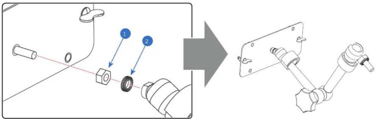
Image 6-21
- Slide a washer (reference 4 Image 6-22) over the base of the swivel arm (reference 3 Image 6-22) and insert the base of the swivel arm into one of the four possible mounting holes (reference 1 & 2 Image 6-22) at the of the projector.
Note: Which mounting hole to use depends on the operator preferences. In the illustration below the swivel arm is installed into the mounting hole nearest by the Local Keypad of the projector.
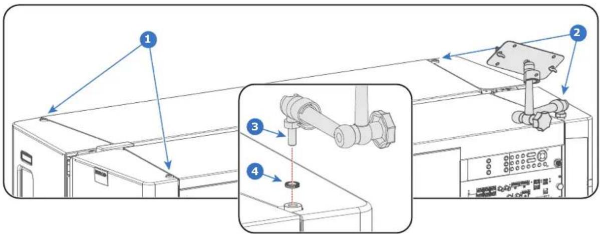
Image 6-22
- Place the Touch Panel interface upon the mounting plate of the swivel arm and fasten the two wing nuts (reference 5 Image 6-23) as illustrated.
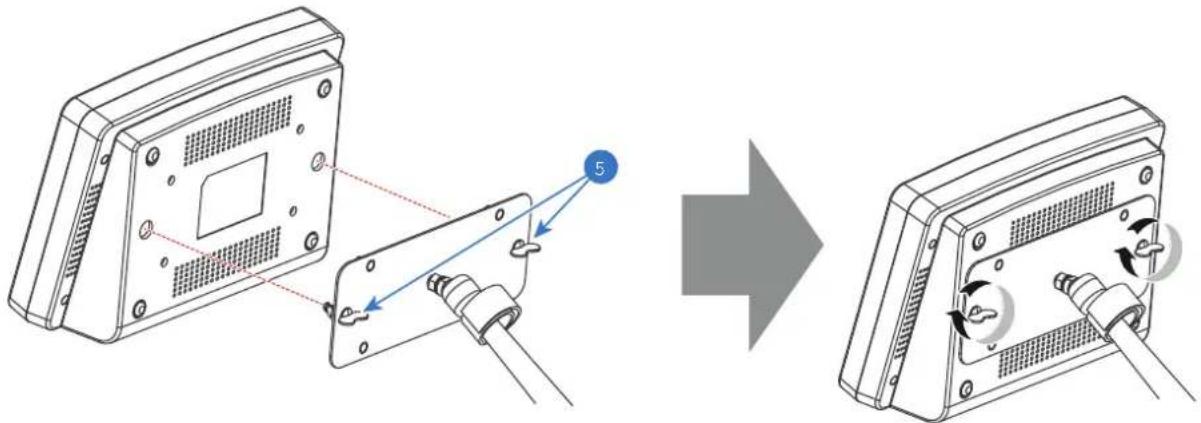
Image 6-23
- Connect the DC plug, the RJ45 Ethernet plug and the D-SUB plug of the customized cable into their respective sockets on the Touch Panel interface.
Physical installation
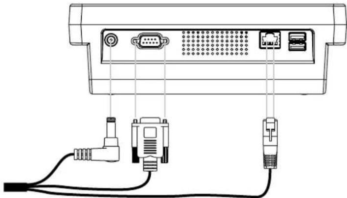
natural_image
Diagram of a computer monitor rear panel with connected cables and connectors (no text or labels)Image 6-24
- Connect the circular plug of the customized cable with the circular socket (reference 6 Image 6-25) at the right side of the Local Keypad of the projector.
! Caution: To avoid connector damage, align the pins before you connect the customized cable.
Note: Ensure to tighten the locking nut on the connector.
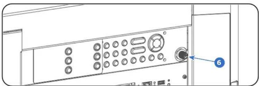
natural_image
Technical line drawing of a computer tower panel with labeled ports and buttons (no text or symbols beyond the number 6)Image 6-25
-
Attach the multi cable to the swivel arm using the two Velcro strips.
-
Position the Touch Panel interface in the desired location. Hold the Touch Panel interface with one hand, release the swivel lock (reference 7 Image 6-26), reposition the Touch Panel interface in the desired location, and fasten the swivel lock.
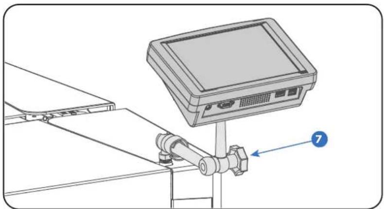
natural_image
Technical line drawing of a mounted electronic device with a labeled component (7), no text or symbols present.Image 6-26
! Caution: Never release the central swivel lock without supporting the Touch Panel interface.
Lenses & Lens selection
7
About this chapter
This chapter gives an overview of available lenses for your Thor series and explains how to select the best suited lens for a specific situation using the lens calculator. Also, it is explained how to install and remove a lens from the projector Lens Holder and how to shift, zoom and focus the lens.

CAUTION: Never transport the projector with a Lens mounted in the Lens Holder. Always remove the Lens before transporting the projector. Neglecting this can damage the Lens Holder and Prism.

CAUTION: Caution when removing or installing the lens! Fragile parts at the inner side of the Lens Holder.

Each time a lens is manipulated (e.g. removed and installed in a projector), it needs to be homed and returned.
Overview
• Available lenses
- Lens selection
- Lens installation
- Lens removal
• Lens shift, zoom & focus
7.1 Available lenses
Which lenses are available for my projector?

The table below is subject to changes and was last updated on 22/10/2019. Consult Barco's web site for the most recent information about available lenses.
| Order No | Type | Throw Range Projector series | ||||
| 2K 4K | DP2K-B DP4K-B DP2K-BLP DP4K-BLP DP4K-L | DP4K-P Prometheus I Prometheus II | DP4K-LHC DP4K-BLPHC Thor Prometheus III | |||
| R9856504 R9856525 | HB 1 | .25-1.90 1.13-1.72 X | ||||
| R9856506 HB | 1.25-1 | .91 1.13-1.72 X | ||||
| R9856294 R9856526 | HB | 1.49-2.05 1.35-1.86 X | ||||
| R9856297 R9856527 | HB | 1.61-2.31 1.46-2.10 X | ||||
| R9856300 R9856528 | HB 1 | .82-2.86 1.65-2.60 X | ||||
| R9856303 R9856529 | HB 2 | .21-3.70 2.00-3.35 X | ||||
| R9855947 HB | 2.8-5.5 | 2.53-4.98 X | ||||
| R98565042 HC | 1.13-1.72 X | X | ||||
| R98562942 HC | 1.35-1.86 X | X | ||||
| R98562972 HC | 1.46-2.10 X | X | ||||
| R98563002 HC | 1.65-2.60 X | X | ||||
| R98563032 HC | 2.00-3.35 X | X | ||||
| R98565043 | VHC | 1.13-1.72 | X | |||
| R98562943 | VHC | 1.35-1.86 | X | |||
| R98562973 | VHC | 1.46-2.10 | X | |||
| R98563003 | VHC | 1.65-2.60 | X | |||
| R98563033 | VHC | 2.00-3.35 | X | |||
7.2 Lens selection
Which lens do I need?
- Browse to Barco's website on www.Barco.com.
- Go to the product page of the desired product.
- On the product page, go to the Tools section and click Lens calculator.
The lens calculator will be displayed.
The lens calculator allows you to have an overview of which lenses are suitable for your specific projector setup. Just make your selection of parameters and all possible configurations are displayed.

Barco.com | Cinema Calculator
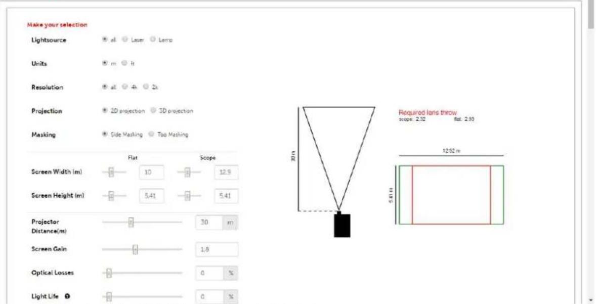
Image 7-1: Example of the Digital Cinema Lens calculator tool

Take into account that when the projector is tilted the Screen Width you have to fill in should be larger than the physical screen width due to the keystone distortion of the projected image. How much larger depends on the amount of tilt.

Due to production tolerances the real distances can differ by 2% from the calculated values. For critical situations (fixed installs that use the lens at one of its extreme zoom positions) this should be taken into account.
7.3 Lens installation

If no lens is installed the lasers of the Thor series series projector can not be powered. The Standby button en Light button will light up red. The Projector Toolset will also show the error message that there is no lens installed.
How to install a lens into the Lens Holder?
- Remove the plastic cover in the opening of the Lens Holder if not removed yet. Place the Lens Holder in the "unlocked" position by moving the lens lock handle (reference 1 Image 7-2) to the right. Then, take away the plastic cover.
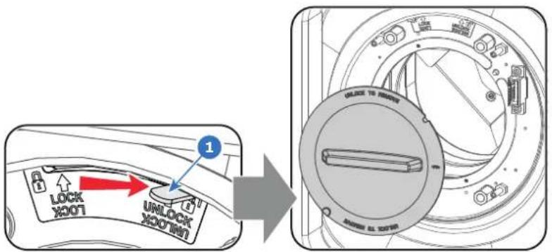
Image 7-2
- Take the lens assembly out of its packing material and remove the lens caps on both sides.

Caution: Do not touch the glass of the lens!
-
Ensure that the Lens Holder stands in the On-Axis position (horizontal and vertical mid position). As best as possible.
-
Place the Lens Holder in the "locked" position by moving the lens lock handle (reference 1 Image 7-3) to the left, away from the lens power supply socket (reference 2 Image 7-3).
-
Gently insert the lens in such a way that the lens connector matches the socket. To prevent collision of the lens ensure you centre the lens and keep it on-axis while approaching.

Warning: Do not release the Lens yet, as the Lens may fall out of the Lens Holder.
- Push the lens completely against the Lens Holder front plate. An audible click should be noticed. Once seated, there may be no airgap between lens flange and Lens Holder front plate.

Caution: Ensure that the lock handle remains in the "locked" position.
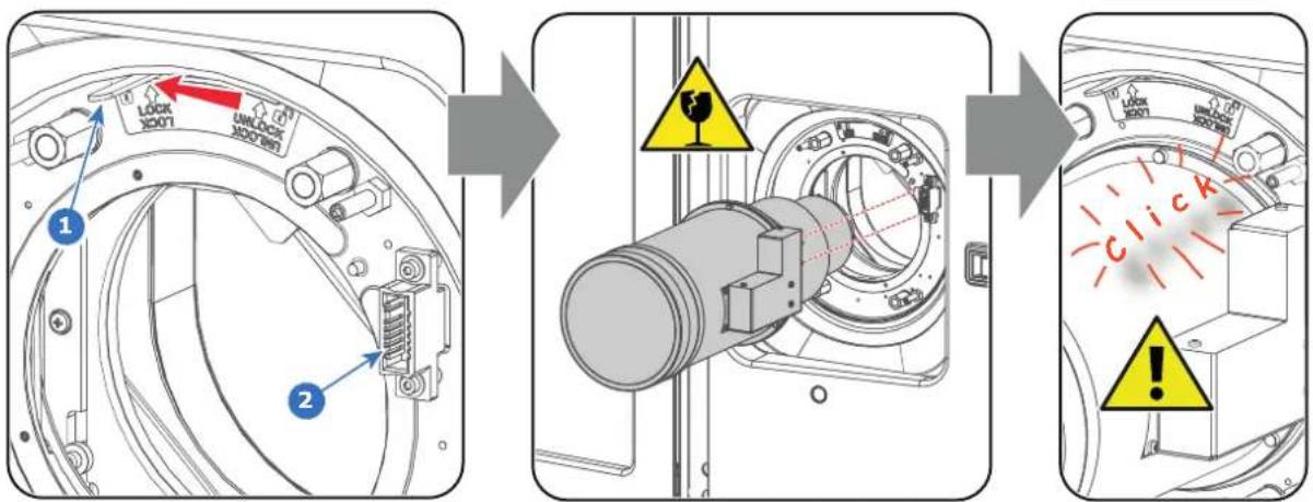
Image 7-3
Note: For frequent installation and removal of the lens it is recommended to install the lens while the lock handle is in "open" position (to the right) and put the lock handle in "locked" position once the lens is inserted. Then check if the lens is properly installed by trying to pull the lens out of the Lens Hold (this alternative procedure result in less wear of the Lens Holder and avoids the risk of moving and misaligning the projector while pushing the lens inwards).
-
Check if the lens is really secured by trying to pull the lens out of the Lens Holder.
-
Activate the corresponding lens parameters for the installed lens. (See user guide of the "Projector Toolset" chapter Installation > Advanced > Lens parameters)

Caution: Not using the correct lens parameters could result in lens damage.
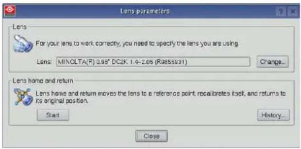
Image 7-4
- Perform a lens HOME & RETURN operation. (See user guide of the "Communicator" chapter Installation > Advanced > Lens parameters)

Note: The HOME & RETURN operation enables the projector to determine the reference positions of the motorized ZOOM and FOCUS barrels of the installed lens.

A Spatial Color Calibration (SCC) has to be execute in case of a first install or in case a High Brightness lens is swapped with a High Contrast lens or vice versa. See user guide of the Communicator for detail SCC calibration instructions.

CAUTION: Never transport the projector with a Lens mounted in the Lens Holder. Always remove the Lens before transporting the projector. Neglecting this can damage the Lens Holder and Prism.
7.4 Lens removal
How to remove a lens from the Lens Holder?
- Support the lens with one hand while you unlock the lens holder by sliding the lock handle (reference 1 Image 7-5) towards the "unlocked" position as illustrated.
- Gently pull the lens out of the lens holder, maintaining its coaxial direction.
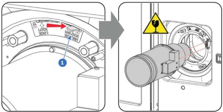
Image 7-5

It's recommended to place the Lens caps of the original Lens packaging, back on both sides of the removed Lens to protect the optics of the Lens.

It's recommended to place the plastic cover of the original projector packaging, back into the lens opening to prevent intrusion of dust. This plastic cover prevents that dust is entering the projector.

If no lens is installed the lasers of the Thor series series projector can not be powered. The Standby button en Light button will light up red. The Projector Toolset will also show the error message that there is no lens installed.
7.5 Lens shift, zoom & focus
Motorized lens adjustment
The Thor series is equipped with a motorized lens shift and zoom & focus functionality.
Maximum shift range
The lens can be shifted with respect to the internal optics of the projector (DMD) which results in a shifted image on the screen (Off-Axis). A 100% shift means that the centre point of the projected image is shifted by half the screen size. In other words, the centre point of the projected image falls together with the outline of the image in an On-Axis projection. Due to mechanical and optical limitations the shift range is limited as well.
All DC4K lenses have a shift range of 50% up, 50% down, 17% left, and 17% right. This range is valid for a throw ratios. Within these shift ranges the projector and lens perform excellently. Configuring the projector outside these shift ranges will result in a slight decline of image quality.
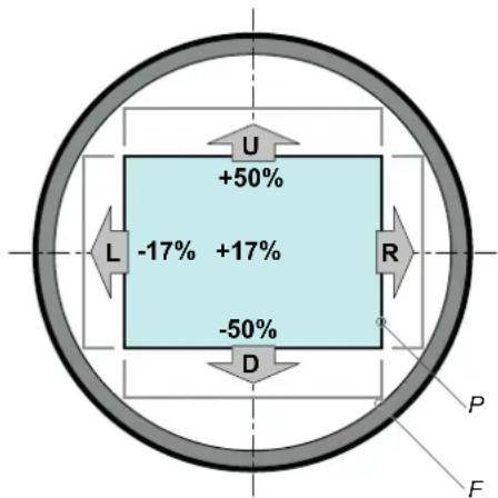
Image 7-6
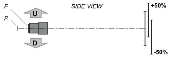
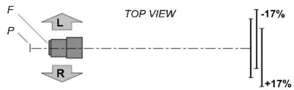
P DMD.
F Field of view.

It's mechanical possible to shift outside the recommended field of view, but this will result in a decline of image quality depending on the used lens and the zoom position of the used lens. Furthermore, shifting too much in both directions will result in a blurred image corner.
How to shift the lens of the Thor series?
- Use the up and down arrow buttons on the Local Keypad to shift the lens vertically and use the left and right arrow buttons on the Local Keypad to shift the lens horizontally.
Image 7-7
How to zoom in or out?
- Use the "+" and "-" zoom buttons on the Local Keypad to zoom in or out.
Image 7-8
How to focus?
- Use the "+" and "-" focus buttons on the Local Keypad to focus the image on the screen.
Image 7-9

Take into account that the lens focus may slightly drift while the lens is warming up from cold to operation temperature. This is a typical phenomenon for projection lenses used with high brightness projectors. The operation temperature of the lens is reached after approximately 30 minutes projection of average video.
Button backlight colors
- WHITE: The default backlight color of the Shift, Zoom and Focus buttons is white which indicates that the button is enabled.
- PURPLE: When pushing the Shift, Zoom or Focus button the backlight color is purple of the part of the button that is pushed. This indicates that the requested action is ongoing.
• RED : The backlight color of the Shift, Zoom and Focus buttons is red in case of end of range.
Input & Communication
8
About this chapter
This chapter describes the functionality of the Local Keypad, the projector Status Light (tail light) and the different input and communication ports of your Thor series projector.
Note that all information about the ICMP(-X) is gathered into one separated chapter: "ICMP(-X)", page 77.
Overview
- Introduction
- Projector Status
- Laser Status
- Local Keypad
• Cinema Controller
8.1 Introduction
General
The Input & Communication side of the Thor series projector consists of a Local Keypad integrated into the projector housing and a card cage with three slots. The rear side of the projector is equipped with a tail light which reflects the status of the projector. The laser status light is located on the top side of the projector.
The projector card cage is equipped with an ICMP(-X). See illustration below. Note that all information about the ICMP(-X) is gathered into one separated chapter: "ICMP(-X)", page 77.
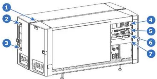
Image 8-1
1 Lasers status light.
2 Projector status light.
3 Communication port with Chillers.
4 Local keypad.
5 ICMP(-X).
6 Barco Cinema Controller.
7 Switch Mode Power Supply (SMPS) for projector electronics (not lasers)

CAUTION: A unit may only be removed from the card cage by qualified service personnel. Removing one of the boards (except for the Cinema Controller or SMPS) will result in an authorization request upon starting.
8.2 Projector Status
About the projector Status Light
The projector Status Light is located at the rear side of the projector (reference 1 Image 8-2). The projector Status Light is a real time indicator of the projector condition.
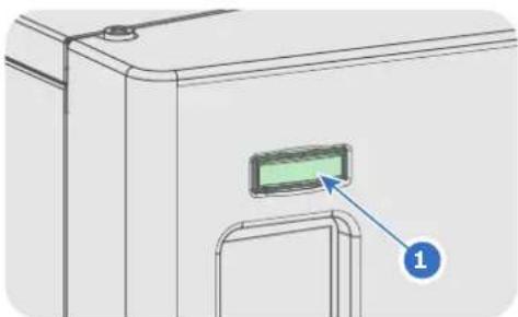
natural_image
Technical line drawing of a door with a green indicator light and blue arrow pointing to it, labeled '1' (no text or symbols beyond label)Image 8-2
Status overview
Depending on the condition of the projector the status light may have 4 colors: Green, Yellow, Red or Blue. Each color represent a different state:
Blinking Green Projector is booting up.
Green Projector is running normally.
Yellow
Projector is running with warnings. Event can go on but a technical intervention might be r future to prevent a complete stop of the projector.
Red
Projector is in error state. Problem could prevent normal operation. Solve the problem bef projector.
Blue Projector runs in notification state. Maintenance action required.
Operational mode
In Operational mode the lasers of the projector are switched OFF but all the electronics of the projector remain fully operational. The projector is ready to activate the lasers and project the image. The status light is not different between Operational mode and Light ON mode.
Standby mode
If the projector is in Standby mode then the status light flashes every ten seconds. The color of the flash depends on the state of the projector. In other words, the color of the flash will be green in normal state (no warnings, no errors, no notifications).
In Standby mode the total power consumption of the projector is less than 15W. All electronics are switched off (including PSUs for the lasers) except for Cinema Controller board and Local Keypad. Only the following functionalities of the projector remains active:
- Local Keypad
- Router LAN and WAN port fully functional
• USB IN port type "B" (Virtual comport RS232) - USB OUT port type "A" (To power handheld devices [500mA MAX]. No other functionality supported)
• GPIO port on the Cinema Controller
Pressing the Standby button in Operational mode for 3 seconds puts the projector in Standby mode. After deconditioning then the projector goes in Standby mode.
Pressing the Standby button in Standby mode for 3 seconds will awake the projector towards operational mode. The status light will blink for a few seconds (booting up all inactive boards) and then lights up continuously.
Enter or leave Standby mode can also be done via two dedicated projector commands (USB/Ethernet), or via two predefined Macros (not editable) with GPIO of the Cinema Controller (not the GPIO of the ICMP(-X)), or via the Communicator.

The projector always boots up in the same mode (E.g. Standby or Operational) as it was powered OFF.
8.3 Laser Status
About the Laser Status Light
The Laser Status Light is located at the rear top of the projector (reference 2 Image 8-3). The Laser Status Light is a real time indicator of the laser condition.
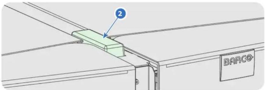
Image 8-3
Status overview
The Laser Status light has only one color: white. The combination of the Laser Status light and the backlight of the Power On/Off button on the Local Keypad indicates a certain condition of the projector. See table below.
Status Light Light Button Meaning
| Off | Continuous white or off | Sealed compartments are DECONDITIONED. Lasers are no service personnel to open the compartments). |
| Blinking(6 seconds) | Blinking green | Indicates the start of the CONDITIONING process. After six will light up continuously. |
| On Blinking green Ongoing CONDITIONING process. Lasers are tested | ||
| Continuous green | Sealed compartments are fully CONDITIONED. Lasers are a projection. | |
| Blinking white | Ongoing DECONDITIONING process. Lasers can be active | |
| Slow blinking | Continuous white or red | Not safe to open the sealed compartments due to risk of con dew point of the boot area is too high.Wait until the status light turns off and remains off. |
8.4 Local Keypad
Identification of the buttons
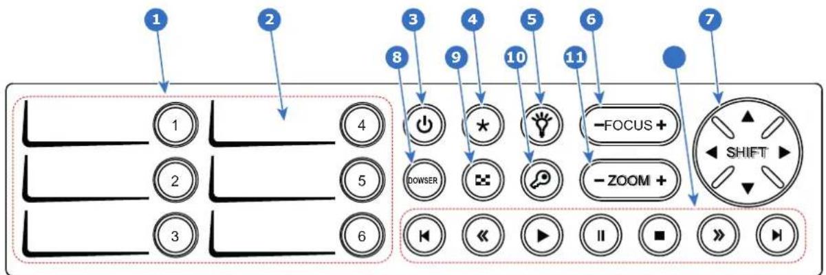
flowchart
graph TD
    A["1"] --> B["2"]
    B --> C["3"]
    C --> D["4"]
    D --> E["5"]
    E --> F["6"]
    F --> G["7"]
    G --> H["8"]
    H --> I["9"]
    I --> J["10"]
    J --> K["11"]
    K --> L["FOCUS +"]
    L --> M["-ZOOM +"]
    M --> N["SHIFT"]
    style A fill:#fff,stroke:#000
    style B fill:#fff,stroke:#000
    style C fill:#fff,stroke:#000
    style D fill:#fff,stroke:#000
    style E fill:#fff,stroke:#000
    style F fill:#fff,stroke:#000
    style G fill:#fff,stroke:#000
    style H fill:#fff,stroke:#000
    style I fill:#fff,stroke:#000
    style J fill:#fff,stroke:#000
    style K fill:#fff,stroke:#000
    style L fill:#fff,stroke:#000
    style M fill:#fff,stroke:#000
    style N fill:#fff,stroke:#000
Image 8-4
Functionality of the buttons
1 Numeric buttons (No.1 - 6)
Each Numeric button (reference 1 Image 8-4) can be linked to a macro which allows you to setup the projector to your requirements with one push of a button. The backlight of the Numeric button is white if a macro is associated with the Numeric button. The backlight is green if the macro associated with the Numeric button is activated. The backlight is red in case one of the actions of the macro failed. Inactive Numeric buttons have no backlight.
When the authorization process is activated with the (security) Key button, the backlight of the Numeric buttons changes to yellow.
2 Marker area
Each Numeric button has a marker area (reference 2 Image 8-4) where you can write down the name of the Macro.
3 Standby button
Pushing the Standby button (reference 3 Image 8-4) for 3 seconds changes the projector mode from Standby mode (energy saving) to Operational mode or vice versa. The backlight of the Standby button is blinking white or green, depending on the requested mode. Once the requested mode is reached the backlight will be continuously lit up green in Operational mode or white in Standby mode.
Enter or leave Standby mode can also be done via a 2 dedicated projector command (USB/Ethernet), or via two predefined Macros (not editable) with GPIO, or via the Communicator.
During projector initialization the backlight of the Standby button is blinking blue.
In case the Light button and the Standby button continuous lights up red indicates that no lens is installed or that the ambient temperature inside the Light Processor compartment is exceeded or that the DMD FRONT or DMD BACK temperature is exceeded.
4 Star button
Star button (reference 4 Image 8-4). Pressing the Star button a few seconds will activate the ICMP reset process.
5 Light button
Light button (reference 5 Image 8-4) switches the lasers ON or OFF.
Pushing the Light button (reference 5 Image 8-4) for 3 seconds will activate or deactivate the lasers of the projector. The backlight of the Light button is blinking white or green, depending on the requested mode. Once the requested mode is reached the backlight will be continuously lit up green when the lasers are activated or white when the lasers are deactivated.
In case the Light button and the Standby button continuous lights up red indicates that no lens is installed or that the ambient temperature inside the Light Processor compartment is exceeded or that the DMD FRONT or DMD BACK temperature is exceeded.
6 Focus button
The Focus button (reference 6 Image 8-4) allows you to focus the projected image on the screen. The backlight of the Focus button is red in case the end of range is reached.
In case no lens (file) is selected the Focus button remains inactive. No backlight.
7 Shift button
The Shift button (reference 7 Image 8-4) allows you to shift the lens up/down or left/right. The backlight of the Shift button is red in case the end of range is reached.
In case no lens (file) is selected the Shift button remains inactive. No backlight.
8 Dowser button
The Dowser button (reference 8 Image 8-4) opens or closes the dowser. The backlight of the Dowser button is green when the dowser is requested to open and white when the dowser is closed. Red indicates an error.
9 Test Pattern button
The Test Pattern button (reference 9 Image 8-4) gives direct access to a limited set of the internal test patterns of the projector. This is a toggle button. To exit the Test Pattern mode toggle through all test patterns. Note that the convergence test pattern is not included in this set. The backlight of the Test Pattern button is blinking green if one of the test patterns is activated and lit ups continuous green if none is activated. In case of failure the button lights up in red.
10 Key button
The (security) Key button (reference 10 Image 8-4) is used for the authorization procedure to clear tamper errors etc. (service purposes, see procedure "Authorization to clear security warning on the projector", page 151). Pin codes can be added/changed with the Communicator. The backlight of the Key button is normally green. If the DCI security is tampered then the backlight of the Key button is red.
11 Zoom button
The Zoom button (reference 11 Image 8-4) allows you to zoom in or out the projected image on the screen. The backlight of the Zoom button is red in case the end of range is reached. In case no lens (file) is selected the Zoom button remains inactive. No backlight.
12 Media control buttons
Buttons (reference 12 Image 8-4) allowing you to navigate through the content on the integrated media server. (this feature is not yet implemented in the software, future expansion).
8.5 Cinema Controller
Location of the communication ports
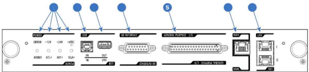
flowchart
graph LR
    A["POWER"] --> B["ERROR +12V -24V +72V ERROR"]
    B --> C["USB"]
    C --> D["IN OUT IN"]
    D --> E["3D INTERFACE USB"]
    E --> F["GENERAL PURPOSE I/O"]
    F --> G["WAN"]
    G --> H["CAN"]
    H --> I["NVM"]
    I --> J["1N"]
    style A fill:#000,stroke:#fff,color:#fff
    style B fill:#000,stroke:#fff,color:#fff
    style C fill:#000,stroke:#fff,color:#fff
    style D fill:#000,stroke:#fff,color:#fff
    style E fill:#000,stroke:#fff,color:#fff
    style F fill:#000,stroke:#fff,color:#fff
    style G fill:#000,stroke:#fff,color:#fff
    style H fill:#000,stroke:#fff,color:#fff
    style I fill:#000,stroke:#fff,color:#fff
    style J fill:#000,stroke:#fff,color:#fff
Image 8-5
Functionality
1 Diagnostic LEDs
The front plate of the Cinema Controller contains 4 diagnostic LEDs to display the status of the power supply (reference 1 Image 8-5):
• +VTEC supply.
- +24V supply.
- +12V supply.
• general power supply (ERROR).
2 USB IN port
The Cinema Controller is equipped with a USB port, type "B" connector, (reference 2 Image 8-5) to connect upstream devices (E.g. PC). This USB port is used to communicate with the projector via RS232 commands (Virtual comport). The USB IN port remains operational in Standby mode.
3 USB OUT port
The Cinema Controller is equipped with a USB port, type "A" connector, (reference 3 Image 8-5) which can be used to power handheld devices within USB spec (MAX 500mA/5V). No other functionality supported (Future expansion). The USB OUT port remains operational in Standby mode.
4 3D INTERFACE
3D interface port (reference 4 Image 8-5. Can be used to connect external 3D devices to the projector. All signals necessary for 3D projection can be provided via this connector. The 3D interface port is disabled if the projector is in Standby mode.
5 GENERAL PURPOSE INPUT/OUTPUT (GPIO)
This 37 pin connector (reference 5 Image 8-5) can be used to send or receive trigger signals from other devices. These input/output pins can be programmed by macros created with the Communicator software. See user's guide of the Communicator, section Macro editor, for more information about this functionality. Note that the General Purpose Inputs accept 24 volt maximum. The GPIO remains operational when the projector is in Standby mode. So, if the factory predefined macro to wake up the projector is assigned to one of the free GPI input pins the projector can be awakened via GPIO. Enter or leave Standby mode can also be done with GPIO via two predefined Macros (not editable).
6 Wide Area Network (WAN)
Wide Area Network (WAN: 10/100/1000 base-T). Use this Ethernet port (reference 6 Image 8-5) to connect the network which contains the DHCP server.
The Thor series can be connected to a WAN (Wide area network) (reference 6 Image 8-5). Once connected to the WAN, users can access the projector from any location, inside or outside (if allowed) their company network using the Communicator software. This software locates the projector on the network if there is a DHCP server or the user can insert the correct IP-address to access the projector. Once accessed, it is possible to check and manipulate all the projector settings. Remote diagnostics, control and monitoring of the projector can then become a daily and very simple operation. The network connectivity allows detection of potential errors and consequently improves service time.
7 Local Area Network (LAN: 10/100/1000 base-T)
Local Area Network (LAN: 10/100/1000 base-T) with built-in Ethernet switch (port 1 and port 2). Use for projector control and automation. E.g. Touch Panel, content server, ... (not for content streaming!) As there is a need to daisy chain projectors when they are on an Ethernet network, an Ethernet switch is built in. the incoming network is hereby available for the internal PC and for the next device in the chain. In this way a 'star' network interconnection can be avoided. The switch used is a stand alone 10/100/1000Mbit Ethernet switch. This assures no influence on the network speed. Furthermore, this Ethernet switch remains operational when the projector is in Standby mode.
The connectors used for these Ethernet ports are of the type RJ45, which is compatible with standard RJ45 cable connector. Straight (most common) as well as cross linked network cables can be used. The 2 ports are functionally identical. Both ports are connected via the projector switch (Auto sensing enabled).
Cinema Controller functions:
- Ethernet Communication to ICMP.
• Virtual COM port (RS232) to BARCO Controller on the USB-IN port.
• Standardized 3D interface on board. - GPIO controls
- Lensholder motors (stepper motors)
• Stores lens files and lens type / Controls lens - Lens motor drivers (DC motors)
• Controls lamp power supply - Stores SNMP key
• Stores Barco IP address and host name - Handles reporting of errors, version info & Barco logs to Communicator
• Controls and monitors keypad (Button module)
• Controls and monitors status lights
• Stores Macro files, Input files, Lens files, 3D files and Light Sensor Calibration file (LSC)
Virtual comport (RS232 serial communication)
The USB-IN port of the communication interface supports RS232 serial communication. You can use the RS232 input port to connect a local PC to your Thor series projector. This way you can configure and control your Thor series projector from your local PC via RS232 (serial) communication protocol.

Do not forget to set the projector's baud rate (default = 115200) to match that of the computer.
Advantages of using RS232 serial communication:
- easy adjustment of the projector via PC (or MAC).
- wide range of control possibilities.
• copying data from the projector (backup).

RS232
An Electronic Industries Association (EIA) serial digital interface standard specifying the characteristics of the communication path between two devices using either D-SUB 9 pins or D-SUB 25 pins connectors. This standard is used for relatively short-range communications and does not specify balanced control lines. RS-232 is a serial control standard with a set number of conductors, data rate, word length and type of connector to be used. The standard specifies component connection standards with regard to computer interface. It is also called RS-232-C, which is the third version of the RS-232 standard, and is functionally identical to the CCITT V.24 standard. Logical '0' is > + 3V, Logical '1' is < - 3V. The range between -3V and +3V is the transition zone.
ICMP(-X)
9
About this chapter
This chapter describes the ICMP (-X) in general, the HDDs, the input ports and the communication ports. Furthermore, the status LEDs are described and the importance of the device certificate is illustrated.
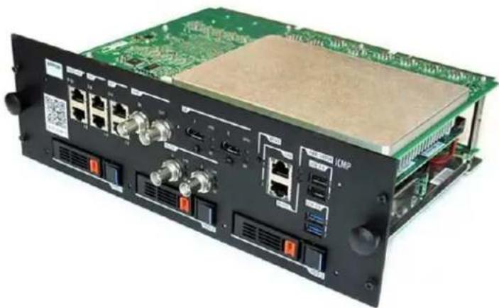
natural_image
Back view of an electronic device chassis with green circuit board and ports (no visible text or symbols)Image 9-1
Overview
• ICMP(-X) introduction
- ICMP(-X) HDD
• What are the possible HDD swaps
• Installing a HDD into the ICMP(-X)
• Removing a HDD from the ICMP(-X)
• HDD status LEDs
• ICMP(-X) status LEDs
• ICMP(-X) device certificate
• Obtaining the Barco ICMP(-X) certificate
• ICMP(-X) configuration via Communicator
• ICMP(-X) communication ports
• ICMP(-X) source input ports
• ICMP(-X) network streaming (Live IP) specifications
• ICMP DisplayPort specifications
• ICMP(-X) SDI specifications
ICMP(-X)
• ICMP(-X) HDMI 2.0 specifications
• ICMP HDMI 1.4 specifications
- ICMP(-X) reset
9.1 ICMP(-X) introduction
About ICMP
The ICMP is a removable electronic assembly situated in the Card Cage of the projector. The ICMP stores, decrypts and decodes DCI cinema content and delivers it to the projector in a usable format, all integrated into a single assembly placed directly in the projector. ICMP is a fully integrated assembly so expected by the operators to facilitate their daily business.
The standard Integrated Cinema Processor functionality from Texas Instruments® is fully integrated into the ICMP. So, the ICMP replaces the ICP board as well.
The ICMP(-X) is located in the Card Cage of the projector.
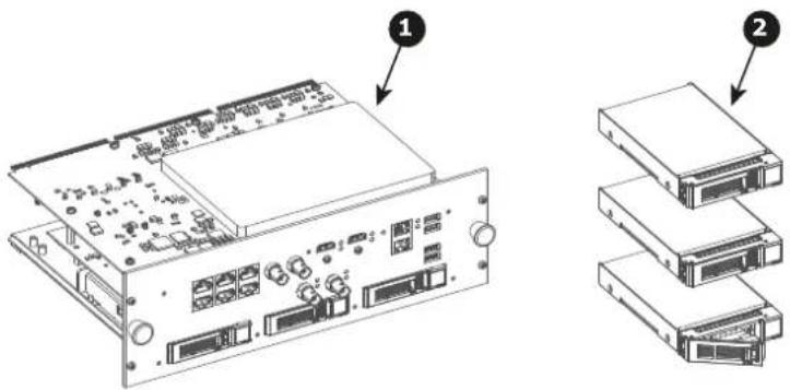
Image 9-2
1 ICMP(-X)
2 HDDs for ICMP(-X)
As an integrated component of the projector, installation and maintenance of the ICMP(-X) requires the same skills and the same precautions as an intervention on the projector itself.
For order info see www.barco.com.
Front face of the ICMP-X
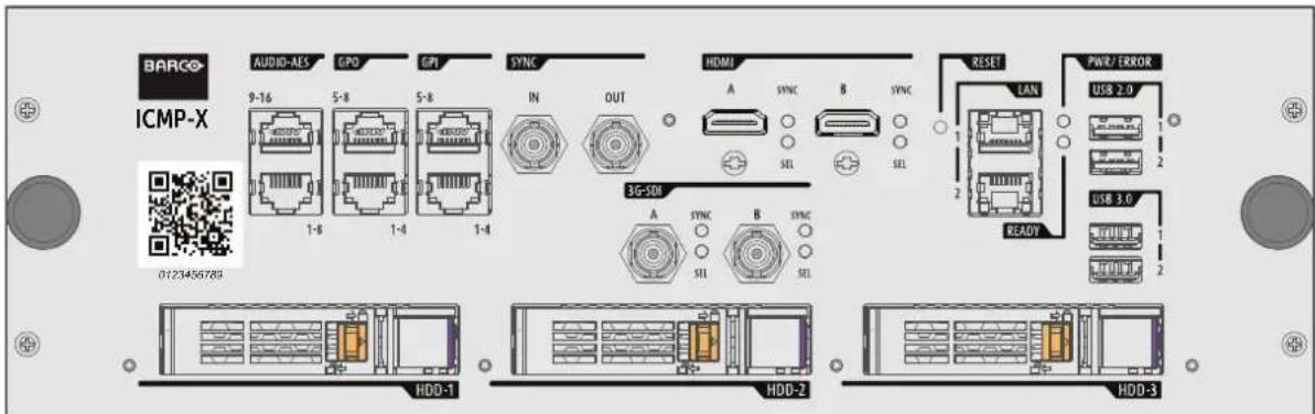
Image 9-3: Front face ICMP-X (standard with storage controller GEN 2)
Front face of the ICMP with HDMI 2.0
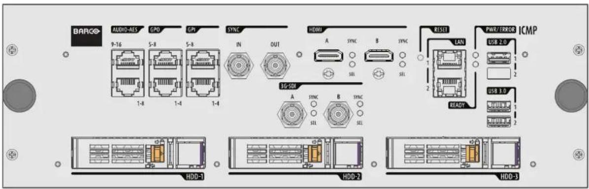
Image 9-4: The model is equipped with two HDMI 2.0 as video source. This ICMP model is no longer available.
Front face of the ICMP with DisplayPort and HDMI 1.4
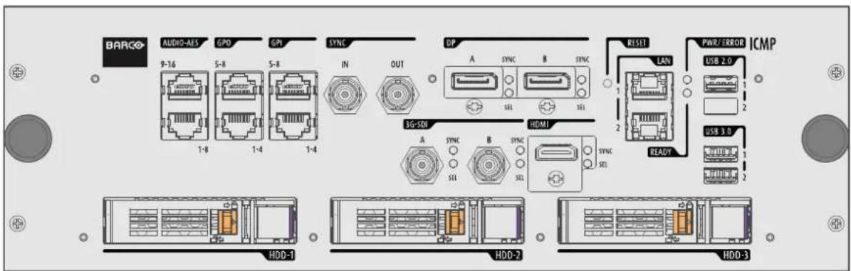
Image 9-5: Some models with DisplayPorts and one HDMI 1.4 (mezzanine) are still present on the field. This ICMP model is no longer available.
GEN1 and GEN2 storage controller
The ICMP-X is equipped with a GEN2 storage controller while the legacy ICMP has an GEN1 storage controller.
The GEN2 storage controller supports SSD and uses another disk initialization type. This implies that HDDs initialized for the legacy ICMP (with GEN1 storage controller) are not interchangeable with the ICMP-X without re-initialization. Note that a re-initialization process result in lost of content. See "What are the possible HDD swaps ", page 83.
It's possible to upgrade an ICMP with a GEN2 storage controller. For more info about the upgrade kit and instructions see Barco website.
How to recognize an ICMP-X or an upgraded ICMP with GEN2 storage controller
At the first glance ICMP-X is very similar to ICMP (the previous generation device) however both devices are not fully compatible and not interchangeable.
Unlike the previous versions the name of ICMP-X appears on the upper left side of the front face (under the Barco logo).
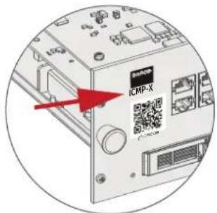
Image 9-6
An upgraded ICMP with GEN 2 storage controller has a label "SSD READY - RAID GEN2" applied under the Barco logo). This sticker comes with the upgrade kit; it will only be there when the "upgrader" applied it.
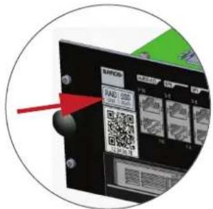
Image 9-7

It's useful to recognize an ICMP from an ICMP-X or upgraded ICMP to know which HDDs can be used without re-initialization.
9.2 ICMP(-X) HDD
About ICMP(-X) HDD
The three HDDs (local storage) in the ICMP(-X), are set up in a RAID 5 configuration. This storage technique, that combines multiple HDD components into a logical unit, manages enough redundancy information to continue to operate properly after the loss of one HDD.
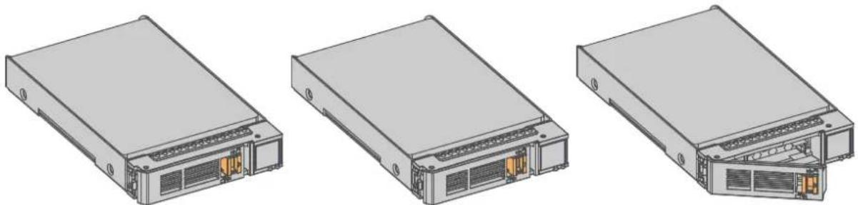
natural_image
Three technical line drawings of server or network equipment modules, showing front, side, and internal components without any text or symbols.Image 9-8

CAUTION: A RAID 5 configuration with three HDDs allows a maximum loss of one disk. With the simultaneous loss of more than one HDDs, data is lost and the RAID must be completely initialized again after replacement of the defect HDDs with new HDDs!
About degraded mode
When a RAID array experiences the failure of one disk, it enters in degraded mode. Content storage and playback remains available on the ICMP(-X).

CAUTION: The loss of one disk causes no serious consequences on the ICMP(-X). But action must be taken quickly because the loss of a second disk will make the RAID system broken. The main cause of the total loss of RAID is due in most cases to the loss of the second disk while the first has not been rebuilt!

A failed drive should be replaced as soon as possible.
About "RAID recovery" process
The restoration from degraded to normal condition of the RAID 5 system is done automatically. When the RAID controller detects a new HDD to replace the failed disk the recovery procedure starts automatically.

CAUTION: The automatic process does not work if more than one disk is lost. In that case the RAID must be completely initialized again!
About RAID broken
When more than one HDD is out of order, the RAID is considered as 'broken' and the content is lost. The fai HDDs must be changed and a new RAID must be created.
Exchange or re-use of a disk set
It's possible to have several sets of disks with one ICMP or to reuse a complete set of disks coming from another projector with ICMP.
How to exchange:
- Exchange of HDD set between two ICMP(-X)s with the same storage controller:
It is sufficient to insert the three HDDs, from a valid RAID array, and let the system explore the new RAID. The mounting order of the HDDs and the HDD slots do not matter. Of course, when using HDDs from another ICMP(-X) it is necessary to retrieve from the content distributor the KDMs corresponding to the content and the new ICMP(-X). - Exchange of HDD set between two ICMP(-X)s with a different storage controller:
After inserting the three HDDs it is necessary to perform a manual RAID initialization with (Web) Communicator, the Barco projectors configuration software. The RAID initialization command (e.g. in Web Communicator: Maintenance > Raid Storage) erases any data present on the HDDs and the old content will be lost. This will only take a short while and after this process, the projector will reboot. You can start immediately after booting with the ingest of your content.

The problem of non-compatibility between the two generations of storage controllers is also encountered when installing a new set of hard drives on an ICMP-X. The HDD spare part kits provided by Barco are configured by default to work with a GEN1 storage controller and it is necessary to perform a manual RAID initialization when they are deployed on a GEN2 storage controller.

Label the HDDs with the initialization type (GEN1 or GEN2) to make it visible for which type of storage controller the disks can be used without requiring a re-initialization and lost of content
HDD storage capacity
Make sure that all HDDs in the ICMP(-X) HDD set have the same storage capacity. See label on top of the HDD to know the storage capacity.
HDD storage
The maximum recommended storage period for the drive in a non-operational environment is 90 days. Drives should be stored in the original unopened shipping packaging whenever possible. Once the drive is removed from the original packaging the recommended maximum period between drive operation cycles is 30 days. During any storage period the drive non-operational temperature, humidity, wet bulb, atmospheric conditions, shock, vibration, magnetic and electrical field specifications should be followed.
HDD models validated by Barco
Only the original HDD spare parts provided by Barco or models validated by Barco (see list below) can be used in the ICMP(-X). All deviations from this rule void warranty.
| HDD model ICMP-X ICMP | ||
| 1TB: HGST - Western Digital (order code: HCC541010A9E630 or HCC541010B9E660) | Yes Yes | |
| 1TB: Western Digital black drives (order code: WD10JQLX-22JFGT0) | Yes Yes | |
| 2TB: Seagate (order code : ST2000NX0253) | Yes Yes | |
| 4TB: Seagate SSD (order code: XA3840ME10063) | Yes Yes, only if the GEN1 storage controller is replaced by a GEN2 storage controller. Software version 1.4.2 or higher is needed. | |
9.3 What are the possible HDD swaps
General
There are several possible scenarios for replacing (exchange) hard drives on the ICMP(-X). The situation is different depending on the device type (ICMP or ICMP-X) and whether to replace one or more disks.
Continuity of data present on the disks is also impacted depending on the type of exchange. Degraded operation or RAID initialization may be required.
List of available actions
The following table exposes all possible swaps available concerning HDDs on ICMP(-X):

Replacing drives should always be done while the power is off.
| Type of HDD swap | On ICMP On ICMP-X | |
| 1 HDD replaced. | Content is preserved.ICMP automatically starts rebuild.Process takes about 3-4 hours for 1TB HDD and could takes about 13-14 hours for 4TB HDD. | Content is preserved.ICMP-X automatically starts rebuild.Process takes about 3-4 hours for 1TB HDD and could takes about 13-14 hours for 4TB HDD |
| 3 HDDs replaced separately (previous kit of one disk used three times). | All content will be lost.RAID initialization need to be perform with Communicator.immediately usable after RAID initialization + restart (content can be ingested). | All content will be lost.RAID initialization need to be perform with Web Communicator.immediately usable after RAID initialization + restart (content can be ingested). |
| Barco HDD replacement kit (Spare part kit provided by Barco with a set of 3 hard disks configured to GEN1 storage controller). | RAID initialization does not need to be performed.Content can be ingested immediately. | RAID initialization needs to be perform with Web Communicator.immediately usable after RAID initialization + restart (content can be ingested). |
| Set of 3 HDDs with content reused from an ICMP with GEN1 storage controller. | On an ICMP with GEN1 storage controller:Content is preserved but certificates (KDM) need to be re-ingested.On an ICMP with GEN2 storage controller:All content will be lost.Only usable after RAID initialization + restart (content can then be ingested immediately). | All content will be lost.Only usable after RAID initialization + restart (content can then be ingested immediately). |
| Set of 3 HDDs with content reused from an ICMP-X. | Unit is equipped with an GEN1 storage controller (default configuration):All content will be lost.RAID initialization needs to be perform with Communicator.Unit has been upgraded with a GEN2 storage controller (+ ICMP software 1.4.2 or higher is installed):Content is preserved but certificates (KDM) need to be re-ingested. | Content is preserved but certificates (KDM) need to be re ingested. |
9.4 Installing a HDD into the ICMP(-X)

This procedure assumes that the HDD slot of the ICMP(-X) is empty. If not, see procedure "Removing a HDD from the ICMP(-X)", page 86.

CAUTION: Always use a new empty spare part HDD approved by Barco to replace a malfunction HDD. Do not use a HDD from another ICMP(-X) HDD set.

CAUTION: Always make sure that all HDDs in the ICMP(-X) HDD set have the same storage capacity. See label on top of the HDD to know the storage capacity.
Re-initialization or rebuild of RAID
Installing or exchange one or several HDDs into ICMP (-X) has an impact on data presents on the already inserted drives. RAID integrity depends on the type of HDD swap. Refer to the chapter "What are the possible HDD swaps", page 83.
How to install a HDD?
- Ensure that the projector is switched off.
- Prepare the HDD for insertion by moving the latch towards the left and push the unlock button to open the handle.
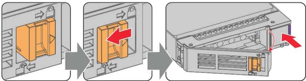
Image 9-9
- Insert the HDD into the HDD slot. Ensure that the handle is sufficiently open so that the hook (reference 1) of the handle can pass the front plate of the ICMP(-X).
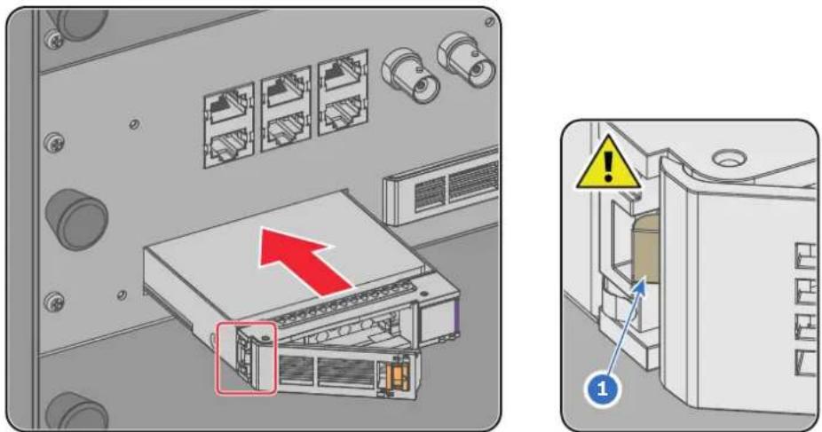
Image 9-10
- Push the HDD completely and firmly inside its slot, close the handle, and move the latch towards the right.
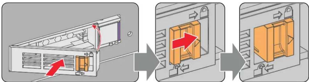
Image 9-11
- Switch on the projector.

In case you replace one HDD (e.g. degraded mode) the ICMP(-X) automatically starts with the RAID recovery process. The red LED of the HDD which has to be rebuilt is blinking. This process takes about 200 GB per hour. Once the RAID is completed the red LED turns off.

CAUTION: It's strongly recommended to complete the RAID recovery process prior to starting a show. This to ensure that the content integrity is preserved and that the show is not interrupted.
9.5 Removing a HDD from the ICMP(-X)

In case the ICMP(-X) has to be returned to factory (e.g. for repair) the non defective HDDs should be removed and kept.
How to remove a HDD?
- Switch off the projector.
- Moving the latch towards the left.
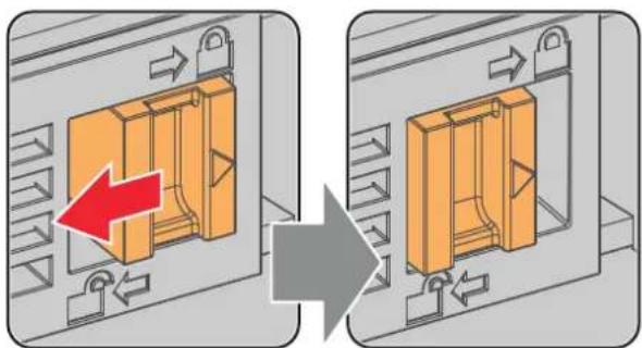
natural_image
Diagram showing a 3D mechanical component being rotated, with arrows indicating direction (no text or symbols present)Image 9-12
- Push the unlock button to open the handle.
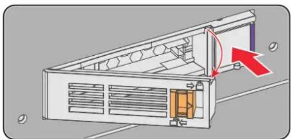
natural_image
Diagram of a device housing with ventilation slots and a red arrow indicating direction (no text or symbols)Image 9-13
- Pull the HDD out of its slot.
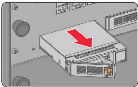
natural_image
Illustration of a server rack with a red downward arrow indicating compression or disassembly (no text or symbols present)Image 9-14

To install an HDD, see the following procedure: "Installing a HDD into the ICMP(-X)", page 84.
9.6 HDD status LEDs
HDD status LEDs
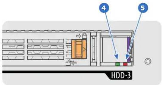
Image 9-15
4 HDD I/O LED
5 RAID LED
Status LEDs on ICMP(-X)
HDD I/O RAID HDD Status
| Off Off HDD idle / disk in RAID OK. | |||
| Blinking green Off HDD I/O activity / disk in RAID OK. | |||
| Blinking green Slow blinking red | HDD disks not (yet) initialized (not supported on ICMP with GEN1 storage controller). | ||
| Blinking green Fast blinking red | HDD I/O activity / RAID rebuilding. | ||
| Off Red | HDD idle / Disk error. Consult the following troubleshooting table for curative actions. | ||

When entering a new HDD in an ICMP(-X), the HDD RAID LED will be full red for a short time. This is not an error, the HDD has not yet been "recognized" by the projector and ICMP(-X).
Once the HDD has been accepted by the ICMP(-X), the full red LED will start blinking in accordance with the previous status table.
If the LED remains full red, an error has occurred. In this case, consult the following troubleshooting table for curative actions.
Troubleshooting
Situation
One disk failed (red LED) + RAID degraded.
The ongoing event is not interrupted.
Note: The disk status (RAID degraded) can be retrieved via the (Web) Commander. See user guide of the (Web) Commander.
Solution
- Switch off the power.
- Replace the defect HDD with approved model of the same storage capacity. See procedure "Removing a HDD from the ICMP(-X)", page 86, and "Installing a HDD into the ICMP(-X)", page 84. Ensure to insert the HDD firmly.
- Switch on the power.
Result: As soon the new HDD is detected by the ICMP(-X) the rebuild of the RAID is started (Blinking red LED).
One disk failed (red LED) + Error 10580 "local storage not available".
Note: The disk status (Error code) can be retrieved via the (Web) Commander. See user guide of the (Web) Commander.
- Switch off the power.
- Replace the defect HDD with approved model of used the same storage capacity. See procedure "Removing a HDD from the ICMP(-X)", page 86, and "Installing a HDD into the ICMP(-X)", page 84. Ensure to insert the HDD firmly.
Situation Solution
| 3. Switch on the power.Result: As soon the new HDD is detected by the ICMP(-X) the rebuild of the RAID is started (Blinking red LED). | |
| Multiple disks failed (multiple red LEDs) + Error 10573 “The RAID is broken”.Note: The disk status (RAID broken) can be retrieved via the (Web) Commander. See user guide of the (Web) Commander. | 1. Switch off the power.2. Replace all defect HDDs with approved models of the same storage capacity. See procedure “Removing a HDD from the ICMP(-X)”, page 86, and “Installing a HDD into the ICMP(-X)”, page 84. Ensure to insert the HDDs firmly.3. Switch on the power.4. Start “RAID Initialize”. See user guide of the (Web) Communicator.Result: a new empty RAID is created. |
| A set of HDDs initialized for a GEN 2 storage controller is installed on a GEN 1 storage controller (All red LEDs remain off) + Combination of three errors (10580 “local storage not available”, 10585 “storage mount failed”, 10573 “the RAID is broken”)Note: The disk status (Error code) can be retrieved via the (Web) Commander. See user guide of the (Web) Commander. | 1. To avoid any misidentification, double check ICMP model and if HDD model is compatible with installed storage controller (see list of HDD models validated by Barco).2. Start “RAID Initialize”. See user guide of the (Web) Communicator. Note that all content will be lost!Result: a new empty RAID is created. |
| All HDD LEDs remain off + Error 10580 “local storage not available”.Note: The disk status (Error code) can be retrieved via the (Web) Commander. See user guide of the (Web) Commander. | 1. Switch off the power.2. Reseat all HDDs. See procedure “Removing a HDD from the ICMP(-X)”, page 86, and “Installing a HDD into the ICMP(-X)”, page 84. Ensure to insert the HDDs firmly.3. If problem remains try “RAID Initialize”. See user guide of the (Web) Communicator. Note that all content will be lost!4. If problem remains contact Service for further instructions. |

In case the ICMP(-X) has to be returned to factory (e.g. for repair) the non defective HDDs should be removed and kept.
9.7 ICMP(-X) status LEDs
ICMP(-X) status LEDs and Reset button
LEDs on ICMP(-X) front panel give information on the status of the device.
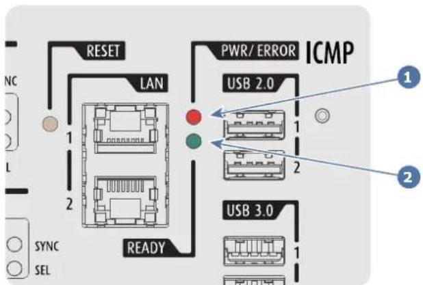
Image 9-16
1 Power / Error LED
2 Ready LED
Status overview PWR/ERROR and READY LEDs:
PWR/ERROR READY
ICMP(-X) Status
| Off Off Turned off | ||
| Red Off Board reset or FIPS error | ||
| Blinking Green Off Boot loader | ||
| Blinking Green Blinking Orange Operating System start up | ||
| Blinking Green Orange Security Manager - Image Integrity tests | ||
| Blinking Green Blinking Yellow Security Manager - Self Test | ||
| Blinking Green Yellow Security Manager - FPGA self-test | ||
| Green Blinking Green Starting Applications | ||
| Green Green Applications started in normal mode | ||
| Green Orange Applications started in degraded mode | ||
| Blinking Red Off FIPS error | ||
| Green Blinking Orange Update ongoing | ||
| Orange Orange Update done |
9.8 ICMP(-X) device certificate
Purpose of the Barco ICMP(-X) device certificate
The device certificate (*.pem) of the Barco ICMP(-X) is a digital certificate signed by Barco which is required when ordering the KDMo play a DCP that is ingested on the ICMP(-X). The device certificate is stored inside the ICMP(-X) and on a web server.
The (WEB) Commander or Communicator can be used to retrieve the device certificate directly from the ICMP (-X). To retrieve the device certificate from the website the QR (Quick Response) code can be used. See procedure "Obtaining the Barco ICMP(-X) certificate", page 91.
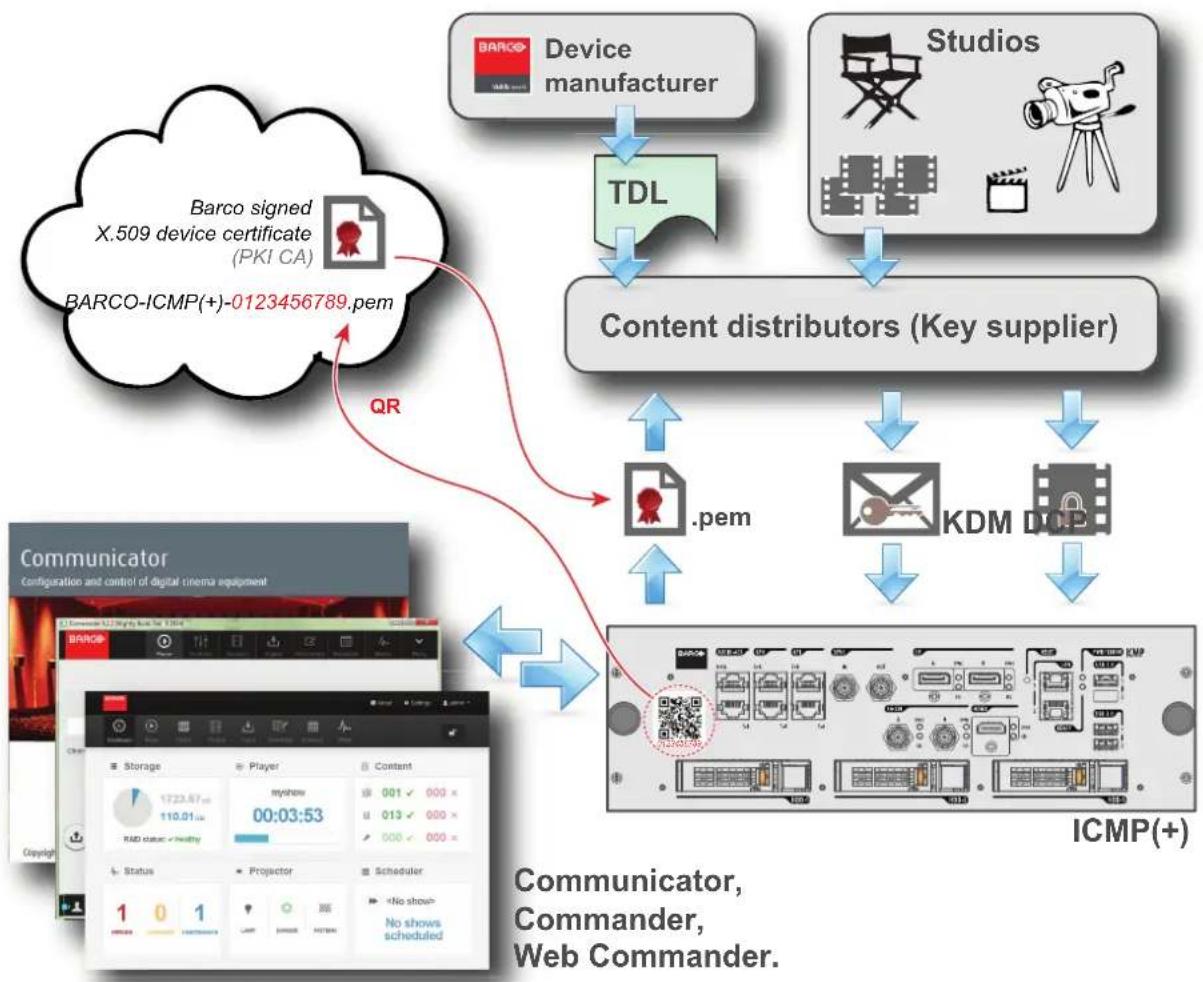
flowchart
graph TD
    A["Barco signed X.509 device certificate (PKI CA)"] -->|QR| B["Content distributors (Key supplier)"]
    C["Device manufacturer"] --> D["TDL"]
    E["Studios"] --> D
    F["Communicator"] --> G["ICMP(+)"]
    H["Communicator, Commander, Web Commander."] --> I["Community Controller"]
    style A fill:#f9f,stroke:#333
    style C fill:#f9f,stroke:#333
    style E fill:#f9f,stroke:#333
    style F fill:#ccf,stroke:#333
    style H fill:#ccf,stroke:#333
Image 9-17
Trusted Device List (TDL)

The Goal of the TDL is to maintain timely and accurate information on participating auditoriums so that participating subscribers can obtain information needed to issue KDMs. The TDL has several data sources: Device manufacturers, Exhibitors, Deployment Entities, Integrators, Service Providers (interacting with Exhibitors), regional authorities and Support.
Public Key Infrastructure (PKI)

PKI is a framework for creating a secure method for exchanging information based on public key cryptography. The foundation of a PKI is the certificate authority (CA), which issues digital certificates that authenticate the identity of organizations and individuals over a public system such as the Internet. The certificates are also used to sign messages, which ensures that messages have not been tampered with.
\*.pem

Privacy-enhanced Electronic Mail. File format used to distribute digital signed certificates. Base64 encoded DER certificate, enclosed between "____BEGIN CERTIFICATE____" and "____END CERTIFICATE____"
Key Delivery Message (KDM)

The security key for each movie is delivered in a unique KDM for each digital cinema server. The security key is encrypted within the KDM, which means that the delivery of a KDM to the wrong server or wrong location will not work, and thus such errors cannot compromise the security of the movie. The KDM is a small file, and is typically emailed to the exhibitor. To create the correct set of KDMs for a site requires knowledge of the digital certificate in the projection system's media block.
Digital Cinema Package (DCP)

A Digital Cinema Package (DCP) is a collection of digital files used to store and convey Digital Cinema (DC) audio, image, and data streams. The term has been defined by Digital Cinema Initiatives (DCI). General practice adopts a file structure that is organized into a number of usually multi-gigabyte size Material eXchange Format (MXF) files, which are separately used to store audio and video streams, and auxiliary index files in XML format. The MXF files contain streams that are compressed, encoded, and encrypted, in order to reduce the huge amount of required storage and to protect from unauthorized use. The image part is JPEG 2000 compressed, whereas the audio part is linear PCM. The adopted (optional) encryption standard is AES 128 bit in CBC mode. The newer SMPTE standards are used to conform the recommendations among different tool vendors and producers. Interop, the legacy DCP standard, is still required to be supported by DCP players.
Digital Cinema Initiatives (DCI)

DCI is a joint venture of Disney, Fox, Paramount, Sony Pictures Entertainment, Universal and Warner Bros. Studios. DCI's primary purpose is to establish and document voluntary specifications for an open architecture for digital cinema that ensures a uniform and high level of technical performance, reliability and quality control. Note that the DCI specification is not a standard. Standards for digital cinema are the domain of the Society of Motion Picture and Television Engineers (SMPTE). "DCI compliant" is a term used to describe products that conform to the DCI specification. Products that have been tested per the DCI Compliance Test Plan (CTP) are posted at the DCI compliance web site. Notably, DCI compliance does not require compliance to the full set of SMPTE DCP standards. A copy of the most recent DCI specification can be downloaded from the DCI website (http://dcimovies.com).
9.9 Obtaining the Barco ICMP(-X) certificate
Required tools
Smartphone (with auto-focus) or control software (e.g. Communicator, Web Communicator, Commander or Web Commander)
Using the CertID label to download the ICMP(-X) certificate
- Scan the QR code (reference 1) on the front face of the ICMP(-X) with a smartphone. It's recommended to use a smartphone with auto-focus. The QR reader will automatically redirect to the ICMP(-X) certificate download page on the web server.

Note: Instead of downloading the ICMP(-X) certificate you can use the CertID number (reference 2), located below the QR code, in communication with your KDM supplier. Certified KDM suppliers can use this CertID number to retrieve the ICMP(-X) certificate directly.
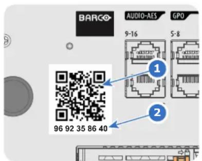
Image 9-18
Using control software to obtain the ICMP(-X) certificate
- Use your control software to download the ICMP(-X) certificate from the ICMP(-X) main board. For detailed instructions, refer to the user guide of your control software, or the projector User Guide.
9.10 ICMP(-X) configuration via Communicator
About ICMP(-X) configuration
Following parameters are available to configure the ICMP(-X):
- Global settings: allows defining name of the ICMP(-X), host name (network identifier) and IP address which can be used for communication with external content devices.
- User settings: definition of all users allowed on the ICMP(-X).
• Server settings: definition of access to servers and storage libraries of content (movies, KDM, etc.). - Player settings: Audio delay and audio output frequency.
- Audio channel: allows defining the mapping of audio channels (content) on each audio output (AES outputs of the ICMP).
- Scheduler setting: Enable/Disable scheduler at startup, delays allowed in scheduler mode and length of schedule history.
• Devices: allows defining communication ports settings, to access external devices controlled by the automation. - Automation Cues: event cues that are triggered from different sources and to which can be assigned actions to be executed by the automation engine.
- Verify internal clock of the ICMP(-X).

All installation and maintenance operations on the ICMP(-X) are performed via Communicator, the Barco configuration software. Please refer to the Communicator user guide for further information.
About Default settings
The restore of factory setting is a feature that allows removing all settings performed on the ICMP(-X) and replaces them with the default values set at the factory. Please refer to the Communicator user guide for further information.
About the ICMP(-X) internal clock
The crystal on the ICMP (-X) board that manages the clock shows a certain drift (all crystals do). With the Communicator the internal clock can be adjusted. This maintenance action should be repeated every 3 months. When neglected the system will locks up.
From ICMP(-X) software version 1.2.1 onwards it is possible to enable NTP (Network Time Protocol). You have to configure (at installation) an IP address where the ICMP can find a sync signal. From then on, and as long as the connection is active, the ICMP will automatically keep its clock correct. For detailed instructions see user guide of the Communicator.
About test patterns
Often, during ICMP(-X) settings, it could be necessary to resize displayed image. In most of the cases, to achieve this, test patterns are displayed on screen. However, some test patterns are provided on the fly by the projector and can not be resized.
List of test patterns that can be resized:
• 2K Barco Enabling Bright Outcomes
• BARCO_rgb_primarylogo_red_2K
- Convergence_pattern
- Convergence_pattern_green_on_blue
- Convergence_pattern_red_on_blue
- Convergence_pattern_xxB
- Convergence_pattern_xxC
- Convergence_pattern_xxS
- DualStack3D_Left
- DualStack3D_Right
- Focus
- FocusGreen
- FocusWhite
- Framing_uncorrected
- RGB-12bit-Color Bars
• RGB-12bit-Convergence Pattern
• RGB-12bit-Log Step Blue
• RGB-12bit-Log Step Cyan
• RGB-12bit-Log Step Green
• RGB-12bit-Log Step Magenta
• RGB-12bit-Log Step Red
• RGB-12bit-Log Step White
• RGB-12bit-Log Step Yellow
• RGB-12bit-MacBeth ColorChecker
• RGB-12bit-Shallow Horizontal Ramp
• RGB-12bit-Split Ramp
• RGB-12bit-Vertical Bars Plus Crosshairs - SCC 13PNTS
- SCC_27PNTS
9.11 ICMP(-X) communication ports
Location of the communication ports
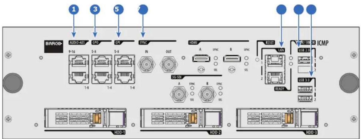
Image 9-19: ICMP(-X) (with HDMI 2.0).
Functionality
1 AUDIO-AES 1-8 (9-16)
ICMP(-X) outputs sixteen audio signals equitably distributed over these two RJ45 connectors, which can be configured independently. The mapping of audio channels (content) on each audio output (AES outputs of the ICMP(-X)) is performed by configuring the ICMP(-X) via the Communicator software. Please refer to the Communicator user guide for further information.
2 GPO 1-4 (5-8)
These RJ45 connectors can be used to send trigger signals to other devices. The mapping of user Cues (output Cues) on each General Purpose Output (GPO) is configured via the Communicator software. Please refer to the Communicator user guide for further information.
3 GPI 1-4 (5-8)
These RJ45 connectors can be used to receive trigger signals from other devices. The mapping of the General Purpose Input (GPI) on each input Cues is configured via the Communicator software. Please refer to the Communicator user guide for further information.
4 SYNC IN / OUT
Synchronization signal IN and OUT: Reserved for multiple-projector projection. Use a 50 Ohm coaxial cable to connect the sync signal from projector to projector.
5 LAN 1 (2)
The ICMP(-X) can be connected to a LAN (local area network) using one of the Ethernet ports. These LAN port are used for 'content' transfer.
NOTE: These ports are optionally used to connect to external content storage sources. Control of the ICMP(-X) is done via the same IP address as the projector.
6 USB 2.0
The ICMP(-X) can be connected to a USB 2.0 Media to load content. The USB port can be used to load content (DCP) or keys (KDM).
NOTE: It is recommended to use the USB 3.0 ports for faster ingest.
7 USB 3.0
The ICMP(-X) can be connected to a USB 3.0 Media to load content. The USB port can be used to load content (DCP), or keys (KDM), or software update.
NOTE: These ports are recommended for fast ingest when connected to an appropriate USB 3.0 source.
USB

Universal Serial Bus (USB) is an industry standard developed in the mid-1990s that defines the cables, connectors and communications protocols used in a bus for connection, communication, and power supply between computers and electronic devices. USB 2.0 (also called "Hi-Speed"), adding higher maximum signaling rate of 480 Mbit/s (effective throughput up to 35 MB/s or 280 Mbit/s), in addition to the "USB 1.x Full Speed" signaling rate of 12 Mbit/s.[16] USB 2.0 connectors are usually colored black. USB 3.0 defines a new SuperSpeed mode with a signaling speed of 5 Gbit/s and a usable data rate of up to 4 Gbit/s (500 MB/s). A USB 3.0 port is usually colored blue, and is backwards compatible with USB 2.0.
9.12 ICMP(-X) source input ports
Location of the source input ports
ICMP and ICMP-X equipped with two HDMI 2.0 (Reference 8, Image 9-20) as video source.
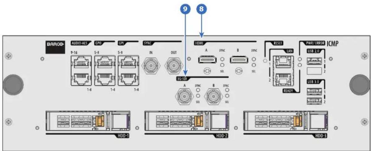
Image 9-20: ICMP(-X) (with HDMI 2.0).
ICMP with DisplayPorts (Reference 11, Image 9-21) and HDMI 1.4 (Reference 10, Image 9-21) are still present on the field.
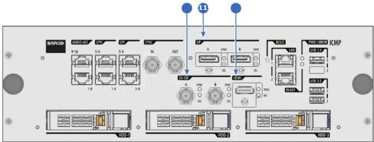
Image 9-21: ICMP (with DisplayPort and HDMI 1.4).
Functionality
8 HDMI A (B)
HDMI 2.0 connector to connect a video source.
NOTE: It is recommended to use the HDMI 2.0 ports for faster transfer of video and audio data.
9 3G-SDI A (B)
SDI connector to connect a video source.
10 HDMI
HDMI 1.4 connector to connect a video source.
11 DisplayPort A (B)
DisplayPort connector to connect a video source.
9.13 ICMP(-X) network streaming (Live IP) specifications
About network streaming
When equipped with a mezzanine, the ICMP (-X) can receive and play streaming content (multicast live streaming or http live streaming). Streaming content (audio/video/text files) is delivered in real time via one of LAN (local area network) connected to one of Ethernet ports of the ICMP (LAN1/LAN2) or Cinema Controller.
For more details concerning playout of Live IP streaming content please refer to the Web Commander user guide: in the chapter dedicated to the show editor a section explains how to manage alternative input clips (the clips dedicated to the alternative media inputs or Live IP streaming content).
Minimum requirements
To use Live IP function of ICMP(-X), the followings are needed:
- ICMP(-X) must be equipped with a video mezzanine board.
- a license need to be installed with (Web) Communicator to enable the functionality.
- a macro named LIVE_IP (used to set Live IP as the input of the video mezzanine board) need to be present on the projector. To do this both the following methods are available:
- a new clone package that contain lcmp_Live_IP.INPUT file (and LIVE_IP macro) could be apply with (Web) Communicator.
- new macro named LIVE_IP based on the file lcmp_Live_IP.INPUT could be created with (Web) Communicator. For more details concerning creation of LIVE_IP macro, please refer to the (Web) Communicator user guide.
It is not necessary to upgrade ICMP(-X) (or video mezzanine board) with new software version to use Live IP function.
Network Streaming
- UDP (multicast)
• HLS (http live streaming)
• from RJ45 network port of Cinema Controller or ICMP(-X) (LAN1/LAN2)
Stream containers
• Mpeg Transport Stream ISO13818-1 with 1 program
• HLS (http live streaming) with segmented MpegTS stream
- MP4 from file
- Webm from file
Video formats
- MPEG2/H.264 4:2:0 up to 1920x1080 (smaller resolutions are upscaled to full screen)
• Standard frame rates: 24/25/30/50/60p and 50/60i
• Fractional frame rates: 24/30/60 x (1000/1001) according to HDMI spec CEA-861-F
• High quality temporal de-interlacing with edge detection
Audio formats
• MP2, MP3, AAC, AC3
• Multichannel output (up to 5.1)
Subtitle formats
• MpegTS timed text support according to DVB spec ETSI EN 300 743
9.14 ICMP DisplayPort specifications
DisplayPort

Digital display interface developed by the Video Electronics Standards Association (VESA). This royalty-free interface is primarily used to connect a video source to a display device such as a computer monitor, though it can also be used to transmit audio, USB, and other forms of data. VESA designed it to replace VGA, DVI, and FPD-Link. Backward compatibility to VGA and DVI by using active adapter dongles enables users to use DisplayPort fitted video sources without replacing existing display devices.
HDCP

High-bandwidth Digital Content Protection is a form of digital copy protection developed by Intel Corporation to prevent copying of digital audio and video content as it travels across DisplayPort, Digital Visual Interface (DVI), High-Definition Multimedia Interface (HDMI), Gigabit Video Interface (GVIF), or Unified Display Interface (UDI) connections, even if such copying would be permitted by fair use laws. The specification is proprietary, and implementing HDCP requires a license.
DisplayPort specifications
Supported Modes:
• DP1.1a, 4-lanes RBR/HBR
- Audio : yes
• Content Protection : HDCP1.4
• Color Depth : 8 bit/component and 10 bit/component.
• 3D-stereo mode : frame sequential (embedded stereosync on DP required from the source)
DisplayPort A and DisplayPort B accept the following video-timings:
| 2D Formats / Single DP Color depth | Port | Display Mode | |
| 640 x 480 @ 60 fps 8 bpc, 10 bpc | Single 2D | ||
| 800 x 600 @ 60 fps 8 bpc, 10 bpc | Single 2D | ||
| 1600 x 1200 @ 60 fps 8 bpc, 10 bpc | Single 2D | ||
| 1280 x 800 @ 60 fps 8 bpc, 10 bpc | Single 2D | ||
| 1280 x 720 @ 60 fps 8 bpc, 10 bpc | Single 2D | ||
| 1680 x 1050 @ 60 fps 8 bpc, 10 bpc | Single 2D | ||
| 1920 x 1080 @ 60 fps 8 bpc, 10 bpc | Single 2D | ||
| 1920 x 1200 @ 60 fps 8 bpc, 10 bpc | Single 2D | ||
| 2048 x 1080 @ 48, 60 fps 8 bpc, 10 bpc | bpc Single 2D | ||
| 2048 x 1536 @ 60 fps 8 bpc, 10 bpc | Single 2D | ||
| 2048 x 2160 @ 30, 48, 50, 60 fps 8 bpc, 10 bpc | bpc, 10 bpc Single 2D | ||
| 3840 x 2160 @ 24 fps 8 bpc, 10 bpc | Single 2D | ||
| 3D Formats / Single DP | Color depth | Port | Display Mode |
| 1920 x 1080 @ 60 fps 8 bpc, 10 bpc | Single 3D | ||
| 2048 x 1080 @ 60 fps 8 bpc, 10 bpc | Single 3D | ||
| 4K Horizontal SPAN 2D - Full | Color depth | Port | Display Mode |
| 2048 x 2160 @ 30, 48, 50, 60 fps 8 bpc, 10 bpc | A+B span | 2D | |
| 4K Horizontal SPAN 2D - Flat | Color depth | Port | Display Mode |
| 1920 x 2160 @ 30, 48, 50, 60 fps 8 bpc, 10 bpc | A+B span | 2D | |
| 4K Horizontal SPAN 3D | Color depth | Port | Display Mode |
| 2048 x 2160 @ 60 fps 8 bpc, 10 bpc | A+B span | 3D | |
Audio formats
• 2 channels / LPCM / 16 bits / 32 kHz, 44.1 kHz, 48 kHz, 88.2 kHz, 96 kHz
• 5.1 format / LPCM / 24 bits / 48 kHz
• 7.1 format / LPCM / 20 bits / 48 kHz
Notes:
- DisplayMode = Single : is applicable to both DisplayPort A, and DisplayPort B input, separately.
- DisplayMode = A+B : inputs DisplayPort A and DisplayPort B are combined to 1 larger image; in this case the 2 DisplayPort links need to be genlocked ( = synchronous and in phase).
- In all cases
- Color Space - Color Sampling:
- YCbCr - 4:4:4
- YCbCr - 4:2:2
RGB - 4:4:4
- Scan Type = progressive.
• Both Nvidia and AMD GPU's will not support color depths of 10 bits/color while in 3D-stereo mode.
• Some Graphical Cards may not permit 10 bits/color at all video timings, because of bandwidth restrictions.
- DisplayPort A and DisplayPort B automatically detect:
- Active Pixels, and Active Lines
- Vertical Refresh
- 8 bits/color - 10 bits/color
- Frame locked
• All input resolutions are scaled towards the desired resolution specified in the screen presentation file.
• Fractional frame rates = (Hz*1000)/1001
9.15 ICMP(-X) SDI specifications
3G-SDI
Serial Digital Interface (SDI) is a serial link standardized by ITU-R BT.656 and the Society of Motion Picture and Television Engineers (SMPTE). SDI transmits uncompressed digital video over 75-ohm coaxial cable within studios, and is seen on most professional video infrastructure equipment. The first revision of the standard, SMPTE 259M, was defined to carry digital representation of analog video such as NTSC and PAL over a serial interface and is more popularly known as standard-definition (SD) SDI. The data rate required to transmit SD SDI is 270 Mbps. With the advent of high-definition (HD) video standards such as 1080i and 720p, the interface was scaled to handle higher data rates of 1.485 Gbps. The 1.485-Gbps serial interface is commonly called the HD SDI interface and is defined by SMPTE 292M, using the same 75-ohm coaxial cable. Studios and other video production facilities have invested heavily on the hardware infrastructure for coaxial cable and have a vested interest in extending the life of their infrastructure. Fortunately, SMPTE recently ratified a new standard called SMPTE 424M that doubles the SDI data rates to 2.97 Gbps using the same 75-ohm coaxial cable. This new standard, also called 3-Gbps (3G)-SDI, enables higher resolution of picture quality required for 1080p and digital cinema.
SDI terminology
Standard HD-SDI signal (Single Link)
1.5Gb/s HD
Standard HD-SDI allows for a single 4:2:2 image to be carried on one cable at 1.485 Gb/s. The image uses the Y Cb Cr colorspace and uses a bit depth of 10 bit per color component.
Due to the data rate limitations only 23.976, 24, 25, 29.970 and 30 fps streams are achievable.
Dual-Link HD-SDI signal
1.5Gb/s
1.5Gb/s

1080p 50/60
or
1080p 4:4:4
Dual-Link HD-SDI is mainly two standard HD-SDI signals carrying a single image stream split between the two cables. The main advantage is that color subsampling is no longer required, and the image can be transmitted in 4:4:4 quality, which then also allows the RGB (or XYZ) color space to be used.
The main link will contain a standard HD-SDI signal, the second (enhancement) link contains the missing Cb and Cr samples.
Depending on the implementation the enhancement link could also contain extra information to increase the bit depth.
3G HD-SDI signal
3Gb/s

1080p 50/60 (Level A)
or
1080p 4:4:4 (Level B)
3G HD-SDI uses a higher data rate (2.97 Gb/s). This allows a single cable interface to achieve the same capabilities of a Dual-Link HD-SDI implementation.
In direct mapping (level A) this is used to achieve higher frame rates. (50, 59.940 and 60 fps streams are supported).
Dual Stream 3G HD-SDI signal
3Gb/s

HD 4:2:2 Signal #1
and
HD 4:2:2 Signal #2
Dual Stream 3G is a specific variant of the 3G signal which combines two completely separate 4:2:2 image streams into a single 3G signal. This can be used to transmit stereoscopic streams by keeping the left and right eye signals together.
SMPTE 292M STANDARD 1.485 Gb/s HD-SDI SIGNALS
Standard HD-SDI (SMPTE 292M) formats
| SMPTE Standard | Source Resolution | Frame Rate | Display Rate | Scan Type |
| SMPTE 296M | 1280 x 720 23.976 | 23.976 | ProgressiveY Cb Cr 4:2:2 10-Bit | |
| 24 | 24 | |||
| 25 | 25 | |||
| 29.970 | 29.970 | |||
| 30 | 30 | |||
| 50 | 50 | |||
| 59.940 | 59.940 | |||
| 60 | 60 | |||
| SMPTE 274MSMPTE 428-8 | 1920 x 1080 | 23.976 | 23.976 | ProgressiveY Cb Cr 4:2:2 10-Bit |
| 2048 x 1080 | 24 | 24 | ||
| 25 | 25 | |||
| 29.97 | 29.97 | |||
| 30 | 30 | |||
| SMPTE 274M | 1920 x 1080 | 23.976 | 23.976 | Segmented frame |
| SMPTE 428-9(SMPTE RP211) | 2048 x 1080 | 24 | 24 | Y Cb Cr 4:2:2 10-Bit |
| 25 | 25 | |||
| 29.97 | 29.97 | |||
| 30 | 30 | |||
| SMPTE 274M 1920 x 1080 25 | 50 | Interlaced | ||
| 29.970 | 59.940 | Y Cb Cr 4:2:2 10-Bit | ||
| 30 | 60 | |||
Dual-Link HD-SDI (SMPTE 372M) formats
| SMPTE Standard | Source Resolution | Frame Rate | Display Rate | Scan Type |
| SMPTE 274M | 1920 x 1080 | 23.976 | 23.976 | Progressive |
| SMPTE 428-8 | 2048 x 1080 | 24 | 24 | Y Cb Cr 4:2:2 12-Bit only |
| 25 | 25 | Y Cb Cr 4:4:4 10 or 12-Bit | ||
| 29.970 | 29.970 | RGB (XYZ) 4:4:4 10 or 12-Bit | ||
| 30 | 30 | |||
| SMPTE 274M | 1920 x 1080 | 23.976 | 23.976 | Segmented frame |
| SMPTE 428-9 | 2048 x 1080 | 24 | 24 | Y Cb Cr 4:2:2 12-Bit only |
| (SMPTE RP211) | 25 | 25 | Y Cb Cr 4:4:4 10 or 12-Bit | |
| 29.970 | 29.970 | RGB (XYZ) 4:4:4 10 or 12-Bit | ||
| 30 | 30 | |||
| SMPTE 274M 1920 x 1080 25 | 29.970 | 50 | Interlaced | |
| 30 | 59.940 | Y Cb Cr 4:2:2 12-Bit only | ||
| 60 | Y Cb Cr 4:4:4 10 or 12-Bit | |||
| RGB (XYZ) 4:4:4 10 or 12-Bit |
Standard HD-SDI (2 × SMPTE 292M) formats
| SMPTE Standard | Source Resolution | Frame Rate | Display Rate | Scan Type |
| SMPTE 292M | 1920 x 1080 | 23.976 | 47.952 | Progressive |
| SMPTE 428-8 | 2048 x 1080 | 24 | 48 | Y Cb Cr 4:2:2 10-Bit |
| 25 | 50 | |||
| 29.97 | 59.940 | |||
| 30 | 60 | |||
| SMPTE 292M | 1920 x 1080 | 23.976 | 47.952 | Segmented frame |
| SMPTE 428-9 | 2048 x 1080 | 24 | 48 | Y Cb Cr 4:2:2 10-Bit |
| (SMPTE RP211) | 25 | 50 | ||
| 29.97 | 59.940 | |||
| 30 | 60 |
The standard HD-SDI interfaces support the Y Cb Cr colorspace (both legal and full range) using 4:2:2 color subsampling.
The Dual-Link HD-SDI interface can be used to carry a single 4:4:4 image, having a color depth of 10 or 12 per component. Both RGB (XYZ) and Y Cb Cr color spaces are supported.
SMPTE 424M 3G HD-SDI 2.970 Gb/s SIGNALS
3G HD-SDI (SMPTE 425) formats
| SMPTE Standard | Source Resolution | Frame Rate | Display Rate | Scan Type |
| SMPTE 296M | 1280 x 720 23.976 | 23.976 | ProgressiveY Cb Cr 4:4:4 10-BitRGB (XYZ) 4:4:4 10-Bit | |
| 24 | 24 | |||
| 25 | 25 | |||
| 29.970 | 29.970 | |||
| 30 | 30 | |||
| 50 | 50 | |||
| 59.940 | 59.940 | |||
| 60 | 60 | |||
| SMPTE 274M | 1920 x 1080 50 | 50 | ProgressiveY Cb Cr 4:2:2 10-Bit | |
| 59.940 | 59.940 | |||
| 60 | 60 | |||
| SMPTE 274M | 1920 x 1080 23.976 | 23.976 | ProgressiveY Cb Cr 4:2:2 12-Bit onlyY Cb Cr 4:4:4 10 or 12-BiRGB (XYZ) 4:4:4 10 or 12-B | |
| 24 | 24 | |||
| 25 | 25 | |||
| 29.97 | 29.97 | |||
| 30 | 30 | |||
| SMPTE 274M | 1920 x 1080 50 | 50 | InterlacedY Cb Cr 4:2:2 12-Bit onlyY Cb Cr 4:4:4 10 or 12-BiRGB (XYZ) 4:4:4 10 or 12-B | |
| 59.940 | 59.940 | |||
| 60 | 60 | |||
| SMPTE 428-9 | 2048 x 1080 23.976 | 23.976 | ProgressiveY Cb Cr 4:4:4 12-BitRGB (XYZ) 4:4:4 12-Bit | |
| 24 | 24 |
Dual Stream 3G HD-SDI (SMPTE 425) formats
| SMPTE Standard | Source Resolution | Frame Rate | Display Rate | Scan Type |
| SMPTE 292M | 1920 x 1080 | 23.976 | 47.952 | Progressive |
| SMPTE 428-9 | 2048 x 1080 | 24 | 48 | Y Cb Cr 4:2:2 10-Bit |
| 25 | 50 | |||
| 29.970 | 59.940 | |||
| 30 | 60 |
9.16 ICMP(-X) HDMI 2.0 specifications
HDMI

HDMI (High-Definition Multimedia Interface) is a compact audio/video interface for transferring uncompressed video data and compressed/uncompressed digital audio data from a HDMI-compliant device ("the source device") to a compatible computer monitor, video projector, digital television, or digital audio device. HDMI is a digital replacement for existing analog video standards.
HDMI 2.0 specifications
HDMI
Both HDMI 2.0 inputs are fully compliant with the HDMI 1.4, 1.4a, 1.4b, 2.0 and 2.0a revisions of the HDMI specification.
Full Range and Limited Range Quantization are supported for all specified formats.
BT.709 and DCI-P3 are supported for all formats. For HDR content (UHD and 4K only) the BT.2020 color coding is supported.
All video streams should have a progressive scan order, with the exception of 1920x1080i 60 fps (interlaced scan).
HDCP
Both HDMI 2.0 inputs are HDCP 1.4 & HDCP 2.2 compliant.
HDR (SMPTE ST 2084)
HDR (High Dynamic Range) is supported on all UHD and 4K formats.
This includes SMPTE ST 2084 (static metadata) and BT.2020 color coding. Requires a license!
HDMI 2.0 Cable requirements
All HDMI cables should work with HDMI 2.0 receivers. There is no such thing as a "4K HDMI cable" even though this is sometimes sold this way. But of course there are quality differences. The "high-speed" cables would be preferred over the "standard-speed" cables. They usually work at higher cable lengths than the standard-speed ones.
The "Premium Certified HDMI" cables are tested to work with high bandwidth as is the case with 4K HDR content. These can be more expensive though. When using active and/or optical cables you should verify if the integrated receiver and sender are HDMI certified to guarantee to work compliant with the HDMI protocol. You can request the HDMI certificate to the manufacturer of the cable.

The ICMP is not supporting Ethernet-over-HDMI and such specific cables are thus not required.
HDMI 2.0 Supported 2D Formats
| Format Frame | Rate | Color coding Bit | depth |
| 1280x720 23.976 | RGB | 8 | |
| 24 | YCbCr 4:4:4 | 10 | |
| 25 | YCbCr 4:2:2 | 12 | |
| 29.97 | |||
| 30 | |||
| 50 | |||
| 59.94 | |||
| 60 | |||
| 1280x720 100 | RGB | 8 | |
| 119.88 | YCbCr 4:4:4 | ||
| 120 | YCbCr 4:2:2 | ||
| 1920x1080 | 23.976 | RGB | 8 |
| 2048x1080 | 24 | YCbCr 4:4:4 | 10 |
| 25 | YCbCr 4:2:2 | 12 | |
| 29.97 | |||
| 30 | |||
| 50 | |||
| 59.94 | |||
| 60 | |||
| 1920x1080 | 100 | RGB | 8 |
| 2048x1080 | 119.88 | YCbCr 4:4:4 | |
| 120 | YCbCr 4:2:2 | ||
| 3840x2160 | 23.976 | RGB | 8 |
| 4096x2160 | 24 25 | YCbCr 4:4:4 | 10 |
| 29.97 | YCbCr 4:2:2 | 12 | |
| 30 | |||
| 3840x2160 | 50 | RGB | 8 |
| 4096x2160 | 59.94 | YCbCr 4:4:4 | |
| 60 | YCbCr 4:2:2 |
HDMI 2.0 Supported 3D (Frame Packing) Formats
| Format Frame | Rate | Color coding Bit | depth |
| 1920x1080 | 23.976 | RGB | 8 |
| 2048x1080 | 24 | YCbCr 4:4:4 | 10 |
| 25 | YCbCr 4:2:2 | 12 | |
| 29.97 | |||
| 30 | |||
| 1920x1080 | 50 | RGB | 8 |
| 2048x1080 | 59.94 | YCbCr 4:4:4 | |
| 60 | YCbCr 4:2:2 | ||
| 3840x2160 | 23.976 | RGB | 8 |
| 4096x2160 | 24 25 | YCbCr 4:4:4 | 10 |
| 29.97, 30 | YCbCr 4:2:2 | 12 | |
| 3840x2160 | 50 | RGB | 8 |
| 4096x2160 | 59.94 | YCbCr 4:4:4 | |
| 60 | YCbCr 4:2:2 |
HDMI 2.0 Supported Audio Formats
| Format | Sample Rate Sample coding Bit depth | |
| 2.0 | 32 | L-PCM 16 |
| 2.1 | 44.1 | 20 |
| 5.1 | 48 | 24 |
| 7.1 | 88.2 | |
| 96 |
HDMI 2.0 Supported Dual (Twin) Link Formats (2D formats only)
| Format Frame | Rate | Color coding Bit | depth |
| 1920x1080 | 23.976 | RGB | 8 |
| 2048x1080 | 24 | YCbCr 4:4:4 | |
| 25 | YCbCr 4:2:2 | ||
| 29.97 | |||
| 30 | |||
| 50 | |||
| 59.94 | |||
| 60 | |||
| 3840x2160 | 23.976 | RGB | 8 |
| 4096x2160 | 24 | YCbCr 4:4:4 | |
| 25 | YCbCr 4:2:2 | ||
| 29.97 | |||
| 30 | |||
| 50 | |||
| 59.94 | |||
| 60 |

Both HDMI2 inputs (port A & port B) should have to same Format, Frame Rate and Color coding.

Port A should contain the 8 most significant bits of the pixel data, where port B should contain the 8 least significant bits of the pixel data. The pixel data will be reconstructed using the all 8 bits of port A and using the 4 most significant bits of port B.
HDMI 2.0 Supported Passive 3D Formats (3D formats only)
| Format Frame | Rate | Color coding Bit | depth |
| 1920x1080 | 24 | RGB | 8 |
| 2048x1080 | 30 | YCbCr 4:4:4 | 10 |
| YCbCr 4:2:2 | 12 | ||
| 1920x1080 | 60 RGB | 8 | |
| 2048x1080 | YCbCr 4:4:4 | ||
| YCbCr 4:2:2 | |||
| 3840x2160 | 24 | RGB | 8 |
| 4096x2160 | 30 | YCbCr 4:4:4 | |
| YCbCr 4:2:2 |

In Passive 3D HDMI2 input port A should contain the pixel data of Left Eye and HDMI2 input port B should contain the pixel data for Right Eye.
9.17 ICMP HDMI 1.4 specifications
HDMI

HDMI (High-Definition Multimedia Interface) is a compact audio/video interface for transferring uncompressed video data and compressed/uncompressed digital audio data from a HDMI-compliant device ("the source device") to a compatible computer monitor, video projector, digital television, or digital audio device. HDMI is a digital replacement for existing analog video standards.
HDMI 1.4 specifications
HDMI1.4a, including HDCP1.4
HDMI 1.4 Supported 2D Formats (progressive)
| Format Frame | Rate | Color coding Bit | depth |
| 720x480 60 RGB | YCbCr 4:4:4 | (8) | |
| YCbCr 4:2:2 | 10 | ||
| 12 | |||
| 720x576 50 RGB | YCbCr 4:4:4 | (8) | |
| YCbCr 4:2:2 | 10 | ||
| 12 | |||
| 1280x720 23.976 | 24 | RGB | 8 |
| YCbCr 4:4:4 | 10 | ||
| 25 | YCbCr 4:2:2 | 12 | |
| 29.97 | |||
| 30 | |||
| 50 | |||
| 59.94 | |||
| 60 | |||
| 100 | |||
| 119.88 | |||
| 120 | |||
| 1680x720 23.976 | 24 | RGB | 8 |
| YCbCr 4:4:4 | 10 | ||
| 25 | YCbCr 4:2:2 | 12 | |
| 29.97 | |||
| 30 | |||
| 50 | |||
| 59.94 | |||
| 6O | |||
| 100 | |||
| 119.88 | |||
| 120 | |||
| 1920x1080 | 23.976 | RGB | 8 |
| 2048x1080 | 24 | YCbCr 4:4:4 | 10 |
| 25 | YCbCr 4:2:2 | 12 | |
| 29.97 | |||
| 30 | |||
| 50 | |||
| 59.94 | |||
| 60 | |||
| 1920x1080 | 100 | RGB | 8 |
| 2048x1080 | 119.88 | YCbCr 4:4:4 | |
| 120 | YCbCr 4:2:2 | ||
| Format Frame | Rate | Color coding | Bit depth |
| 2560x1080 23.976 | RGB | 8 | |
| 24 | YCbCr 4:4:4 | 10 | |
| 25 | YCbCr 4:2:2 | 12 | |
| 29.97 | |||
| 30 | |||
| 50 | |||
| 59.94 | |||
| 60 | |||
| 3840x2160 | 23.976 | RGB | 8 |
| 4096x2160 | 24 | YCbCr 4:4:4 | 10 |
| 25 | YCbCr 4:2:2 | 12 | |
| 29.97 | |||
| 30 |
HDMI 1.4 Supported 2D (Interlaced) Formats
| Format Frame | Rate | Color coding Bit | depth |
| 720x576 25 | 50100 | ||
| 1920x1080 25 | 29.97305059.9460 |
HDMI 1.4 Supported 3D (Frame Packing) Formats
| Format Frame | Rate | Color coding Bit | depth |
| 1280x720 50 | 59.9460 | ||
| 1920x1080 23.98 | 24 |
HDMI 1.4 Supported 3D (Top Bottom) Formats
| Format Frame | Rate | Color coding Bit | depth |
| 1280x720 50 | 59.9460 | ||
| 1920x1080 23.98 | 24 |
HDMI 1.4 Supported Audio Formats
| Format | Sample Rate Sample coding Bit depth | |
| 2 channels 32 | 44 | L-PCM 16 |
| 48 | ||
| 88 | ||
| 96 | ||
| 5.1 channels 24 L-PCM 48 | ||
| 7.1 channels 20 L-PCM 48 |
9.18 ICMP(-X) reset

This procedure requires that ICMP(-X) version 1.2.4 or later is installed.
ICMP(-X) reset possibilities
- The Star button on the local keypad (Not for C- and B-series)
• The ICMP(-X) reset button (labeled Reboot ICMP) in the GUI of the Communicator.
• The ICMP(-X) reset button (labeled media server) in the GUI of the Communicator.
• The ICMP(-X) reset button (labeled Reboot media server) in the GUI of the Commander.
• The ICMP(-X) reset button (labeled Reboot media server) in the GUI of the Web Commander. - The ICMP(-X) hardware reset button located on the front panel of the ICMP(-X) (Not recommended, use only when all other reset possibilities are exhausted!)
How to reset the ICMP(-X)?
- Click on the Control/ICMP/Reboot media server in the GUI of the Web Commander
or
Click on Control/ICMP/Reboot media server in the GUI of the Commander

Note: The behavior could be different depending the projector type. Please, refer to the projector manual to obtain more details.
or
click on Maintenance/Reboot action/media server in the GUI of the Communicator (recommended)
or
click on Contol/projector/power/Reboot ICMP in the GUI of the Communicator (recommended)
or
press the Star button on the local keypad for a few seconds (Not for C- and B-series)
As a result the projector is safely prepared for the ICMP reboot. All ongoing events on the ICMP (e.g. ingest) are requested to end. After a few seconds the ICMP is requested to restart. The READY LED on the front panel of the ICMP starts to blink orange.
In case the ICMP(-X) is installed in DP4K-L series projector the lasers are switched off and the projector remains in the same mode (e.g. Conditioned). The Star button on the local keypad starts blinking green. After the reset of the ICMP(-X) the lasers are switched on again.
Once the READY LED lit continuous green the ICMP(-X) is up and running.
- Did the reset of the ICMP(-X) fail?
▶ If yes, perform a hardware reset as follows:
-
switch off the lasers of the projector or switch of the projector lamp.
-
press the ICMP(-X) hardware reset button a few seconds (reference 3 Image 9-22).

Warning: Resetting the ICMP(-X) with the hardware reset button may cause damage to the content on the HDDs. A re-configuration of the whole system may be required!
As a result the projector is safely prepared for the ICMP reboot. All ongoing events on the ICMP (e.g. ingest) are stopped immediately and the ICMP restarts.
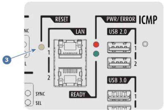
Image 9-22

WARNING: Resetting the ICMP(-X) with the hardware reset button may cause damage to the content on the HDDs. A re-configuration of the whole system may be required!
Starting up 10
About this chapter
This chapter contains the switch ON and switch OFF procedures of your Thor series projector. These procedures highlight all important points to be checked prior to switching the projector ON. This is to ensure a safe startup of the projector.
Overview
• Switching the Thor series projector ON
• Switching the Thor series projector OFF
- Projector ON/OFF cycle explained
10.1 Switching the Thor series projector ON
About the start up process
To start up the Thor series projector the sealed compartment of the Light Processor and the sealed compartment of the Laser Clusters must be brought into a 'condition' which is safe for the electronics to operate (avoid moisture due to extreme cooling). In other words, the temperature and humidity inside these compartments must be brought within specs prior to activating the lasers and Light Processor. The time needed to bring the projector from a deconditioned state into a conditioned state depends on the ambient conditions and can take several minutes. This process is called conditioning.
Start up checklist
- Check if all chillers are correctly installed. See documentation set of the chillers.
- Check if one chiller is equipped with the expansion unit for DMD cooling.
- Check if the Thor series projector is installed onto a stable platform and all covers are installed. See chapter "Positioning the projector at port window", page 46.
- Check if all hoses are properly connected with the chiller(s) and projector. See chapter "Connecting the hoses with projector and chillers", page 49.
- Check if the data cables between chiller(s) and projector are correctly installed. See chapter "Connecting the data cable with projector and chillers", page 51..
- Check if the projector is connected with the mains electricity. See chapter "Connecting the projector with the mains electricity", page 55.
- Check if the ambient temperature and humidity are within specifications. See chapter "Installation requirements", page 36.
- Check if the chiller(s), hoses and projector are completely acclimatized to the same ambient temperature.
- Check if the correct lens is installed for the application and the lens cap is removed from the lens. See chapter "Lens installation", page 63.
- Check if the small drain tubes at the bottom of the projector leads to a water drain or to an open reservoir to capture the condensed water. See chapter "Installation requirements", page 36.

Keep in mind that it can take up to 10 minutes to start the lasers again after they were switched off. If there are only 30 to 45 minutes between the shows it's advisable to keep the lasers on with dowser closed. When the dowser is closed the lasers are automatically dimmed.
Start up procedure
- Switch on the chiller(s). The status light of the chiller(s) should light up white. See documentation set of the chiller.
- Press the Power Switch to switch the projector ON.
As a result the Controller of the projector starts up. All other electronics remain off. The booting process is indicated by the blue blinking backlight of the Standby button on the local keypad. Once the Controller is up and running the backlight of the Standby button is changed to continuous white. This is the projector Standby mode. The status light of the projector also flashes green.

Note: The projector always boots up in the same mode (E.g. Standby or Operation) as it was switched off. This procedure assumes that the projector was switched off in Standby mode.
- Press the STANDBY button on the Local Keypad for three seconds or use the Communicator to put the projector in OPERATIONAL mode.
As a result the backlight of the Standby button starts blinking green indicating the start up of all other projecto electronics. Once this initializing process is done the backlight of the Standby button is changed to continuous green. This is the projector Operational mode. The status light of the projector also lights up green (not flashing).
- Press the LIGHT button on the Local Keypad for three seconds or use the Communicator to activate the lasers.
As a result the backlight of the Light button starts blinking green indicating the projector is in CONDITIONING mode. The laser status light on the top of the projector flashes a few times and then lights up continuously white.
Once the projector is conditioned the backlight of the Standby button is changed to continuous green. Now the lasers are active and light can come out of the projector. The status light of the projector remains green and the status light of the lasers remains white.
- Press the DOWSER button on the Local Keypad or use the Communicator to open the dowser.

Note: The state of the dowser (open or closed) when starting up the projector will be the same as when the projector was switched off. This procedure assumes that the dowser was closed.

CAUTION: See user's guide of the Communicator Touch Panel to operate and control the Thor series.

When for any reason a restart of the projector is required, the content server should be restarted also.
10.2 Switching the Thor series projector OFF
About the switch off process
To switch off the Thor series projector in a safe manner to protect the internal electronics (avoid moisture due to warming up) the temperature inside the sealed compartments has to be brought back to ambient in a controlled manner. This process is called deconditioning.
How to switch the Thor series OFF?
- Press the Standby button for three seconds on the Local Keypad or use the Communicator Touch Panel to switch the projector from OPERATIONAL mode to STANDBY mode. As a result the lasers are deactivated (if activated) and the projector starts to deconditioning the sealed compartments.

Caution: Do not switch off the power from the projector until the laser status light is off. Also make sure not to power off the chiller(s). The chiller(s) should remain on as long as the projector is powered on
- Switch the projector OFF with the power switch.

Keep in mind that it can take up to 10 minutes to start the lasers again after they were switched off. If there are only 30 to 45 minutes between the shows it's advisable to keep the lasers on with dowser closed. When the dowser is closed the lasers are automatically dimmed.
10.3 Projector ON/OFF cycle explained
Projector ON/OFF cycle
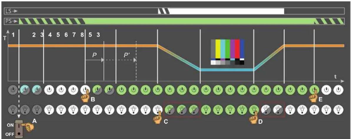
Image 10-1
LS Laser Status light.
PS Projector Status light (tail light).
T Temperature inside sealed compartments.
t time.
A.. Operator manipulations.
E
1..8 Different process stages.
Stage description:
Stage 1 : Projector is switched off. Local Keypad is not active. The projector status light (PS) and the laser status light (LS) are off.
Stage 2 : Cinema Controller of the projector is booting. This process starts as soon as the power switch is switched on (reference A Image 10-1). This process takes several seconds and during this process the backlight of the Standby button is blinking blue. The projector status light is blinking green (in normal condition, no errors and no warnings). The laser status light remains off.
Stage 3 : Projector is in Standby mode. The Cinema Controller is up and running. Only the Standby button and Light button on the Local Keypad are active: The backlight of both buttons is white. The projector status light is blinking green (in normal condition, no errors and no warnings). The laser status light remains off.
Stage 4 : Initialization and PRECONDITIONING. These two processes start simultaneous as soon as the Standby button is pressed for 3 seconds when the projector is in Standby mode (reference B Image 10-1).
The initialization of all electronic boards takes approximately two minutes and during this process the backlight of the Standby button is blinking green. The projector status light remains blinking green (in normal condition, no errors and no warnings). The laser status light remains off. Note that the projector always boots up in the same mode (E.g. Standby or Operation) as it was switched off.
The PRECONDITIONING process verifies if it's safe to turn on the pump of the cooling circuit and to extract humidity from the sealed compartments without having the risk of condensation. The temperature inside the sealed compartments is kept on ambient level. Following sub-stages take place during PRECONDITIONING:
Stage 4.1 : Checking ambient and internal conditions.
Stage 4.2 : Turning pump on. Reaching liquid flow target.
Stage 4.3 : Flow target reached. Conditioning humidity in the projector.
Stage 4.4 : Cooling started.
Stage 4.5 : Reaching liquid temperature target.
Depending on the environmental circumstances (temperature and humidity) the PRECONDITIONING process will reach its target before (reference P Image 10-1) or after (reference P' Image 10-1) the initialization process is completed. In optimal circumstances it will be before.
Stage 5 : Projector is Operational and PRECONDITIONED. All electronic boards are up and running. All buttons on the Local Keypad are active. The backlight of the Standby button is green while the backlight of the
Light button is white. The projector status light is continuous green (in normal condition, no errors and no warnings). The laser status light remains off.
In PRECONDITIONED mode the chillers are operational and the heat dissipation of the DMDs is under control. Heat dissipated by the active formatter boards is removed. Ingesting of content, creating playlist, etc. is already possible on the ICMP. Also the creation of macros etc. is possible if that is feasible without projecting an image (lasers are not active).
Stage 6 : Projector is Operational and in CONDITIONING mode. This process starts as soon as the Light button is pressed for 3 seconds (reference C Image 10-1). The laser status light on the top of the projector flashes a few times and then lights up continuously white. The sealed compartments are cooling down from ambient to operating temperature and humidity is extracted. The conditioning process takes approximately 3 to 15 minutes (depends on the environmental conditions). Following sub-stages take place during CONDITIONING:
Stage 6.1 : Checking ambient and internal conditions.
Stage 6.2 : Turning pump on. Reaching liquid flow target.
Stage 6.3 : Flow target reached. Conditioning humidity in the projector.
Stage 6.4 : Cooling started.
Stage 6.5 : Reaching liquid temperature target.
During CONDITIONING the backlight of the Light button is blinking green. The projector status light is continuous green (in normal condition, no errors and no warnings).
Stage 7 : Projector is Operational and CONDITIONED. Temperature and humidity inside the sealed compartments are within specifications and the lasers are activated. Image is projected on the screen in case the dowser is open and a source or test pattern is selected. The projector status light is continuous green (in normal condition, no errors and no warnings) and the laser status light on the top of the projector lights up continuously white.
Stage 8 : Projector is in Operational and in DECONDITIONING mode. This process starts as soon as the Standby button or Light button is pressed for 3 seconds (reference D Image 10-1) while the projector is in conditioning or conditioned mode. The DECONDITIONING mode brings the system back to the PRECONDITIONED state. The laser status light on the top of the projector remains lighting up white. The sealed compartments are brought back to ambient temperature and humidity extraction is stopped. The deconditioning process takes a few minutes and during this process the backlight of the Light button is blinking white. The projector status light is continuous green (in normal condition, no errors and no warnings).
Scheimpflug
11
About this chapter
This chapter explains the Scheimpflug principle and when to apply Scheimpflug correction upon the projector. In addition to the procedure for Scheimpflug adjustment the procedure to adjust the Back Focal Length is also included in this chapter.
Scheimpflug principle

The "plane of sharp focus" can be changed so that any plane can be brought into sharp focus. When the DMD plane and lens plane are parallel, the plane of sharp focus will also be parallel to these two planes. If, however, the lens plane is tilted with respect to the DMD plane, the plane of sharp focus will also be tilted according to geometrical and optical properties. The DMD plane, the principal lens plane and the sharp focus plane will intersect in a line below the projector for downward lens tilt.
Overview
• Scheimpflug introduction
• Scheimpflug adjustment
• Fixation of the Lens Holder front plate
• Back Focal Length adjustment
11.1 Scheimpflug introduction
What is Scheimpflug?
The lens holder has to be adjusted so that the “sharp focus plane” of the projected image falls together with the plane of the screen (Fp1→Fp2). This is achieved by changing the distance between the DMD plane and the lens plane (Lp1→Lp2). The closer the lens plane comes to the DMD plane the further the sharp focus plane will be. It can occur that you won’t be able to get a complete focused image on the screen due to a ti swing) of the lens plane with respect to the DMD plane. This is also known as Scheimpflug’s law. To solve the lens plane must be placed parallel with the DMD plane. This can be achieved by turning the lens holder t remove the tilt (or swing) between lens plane and DMD plane (Lp3→Lp4).
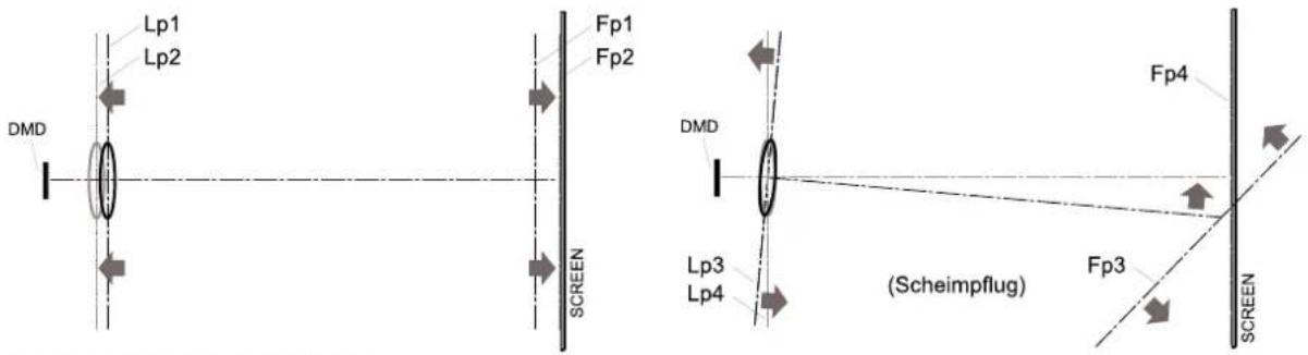
Image 11-1: Scheimpflug principle
Scheimpflug principle

The "plane of sharp focus" can be changed so that any plane can be brought into sharp focus. When the DMD plane and lens plane are parallel, the plane of sharp focus will also be parallel to these two planes. If, however, the lens plane is tilted with respect to the DMD plane, the plane of sharp focus will also be tilted according to geometrical and optical properties. The DMD plane, the principal lens plane and the sharp focus plane will intersect in a line below the projector for downward lens tilt.
Scheimpflug adjustment points
The front plate of the Lens holder is equipped with four bronze (Scheimpflug) nuts and four set screws with lock nut. These screws and nuts are used for Scheimpflug adjustment.
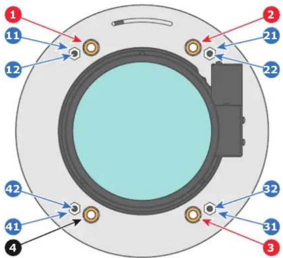
Image 11-2
1 Scheimpflug adjustment nuts No1: Influences 21 Lock nut. the sharp focus plane in the lower left corner of 22 Set screw for nut No2. the projected image. 31 Lock nut.
2 Scheimpflug adjustment nuts No2: Influences 32 Set screw for nut No3. the sharp focus plane in the lower right corner 41 Lock nut. the projected image. 42 Set screw for nut No4.
3 Scheimpflug adjustment nuts No3: Influences the sharp focus plane in the upper right corner of the projected image.
4 Scheimpflug nut No 4: without adjustment functionality.
11 Lock nut. 12 Set screw for nut No1.

Reference 1, 2 and 3 are adjustment points. Reference 4 is a locking point and NOT used during Scheimpflug adjustment.
Only apply a Scheimpflug correction in case the overall focus of the projected image is not equally sharp (can be caused if the projector is NOT in parallel with the screen or a previous misaligned Scheimpflug). Take into account that the consequence of applying Scheimpflug correction upon a screen not in parallel with the projector is that the projected image differs from the rectangle shaped image. In other words “distortion” of the projected image occurs. Masking will be required to solve the distortion.
The disadvantage of Masking is loss of content. Therefore it is strongly recommended to place the projector in parallel with the projection screen and use the SHIFT functionality of the Lens Holder to match the projected image with the projection screen. In case the SHIFT range is not sufficient then the projector can be tilted and Scheimpflug can be applied.
11.2 Scheimpflug adjustment
Required tools
• Allen wrench 3 mm
- Nut driver 13 mm
- Nut driver 10 mm
Preparation steps:
- Ensure that the throw ratio of the installed lens matches the requirements of the application (projection distance and screen size).
Scheimpflug
- Ensure that the correct lens parameters are activated. (See user guide of the "Communicator" chapter Installation > Advanced > Lens parameters)
Note: Selecting the wrong lens parameters will result in an unexpected behavior of the lens when using macros for switching between FLAT and SCOPE (change in picture size and focus).
-
Perform a lens HOME & RETURN operation. (See user guide of the "Communicator" chapter Installation > Advanced > Lens parameters)
-
Project the green focus test pattern.
Image 11-3
-
Zoom the lens for maximum image on the screen (WIDE).
-
Is it possible to focus the center of the projected image?
▶ If yes, the Back Focal Length is OK. Proceed with the next step.
▶ If no, the Back Focal Length needs realignment. Proceed with the procedure “Back Focal Length adjustment”, page 121.
- Unlock and turn out the 4 set screws (reference 11 Image 11-4) of the Lens Holder by 1 centimeter. Use a 10mm nut driver for the lock nuts (reference 21 Image 11-4) and use a 3 mm Allen wrench for the set screw
Image 11-4
-
Fully loosen the Scheimpflug nut at the lower left of the Lens Holder (reference 4 "", page 119). Use a 13 mm nut driver.
-
Optimize the focus of the projected image in the center of the screen (F) using the motorized focus control (Local Keypad).
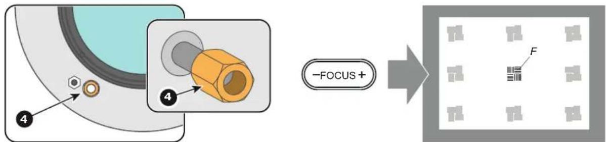
Image 11-5
Scheimpflug adjustment steps:
- Sharpen the image at the bottom left corner of the screen by turning the upper left Scheimpflug adjustment nut (reference 1 Image 11-6). As a result the focus in the center will fade a bit but that's normal.
Caution: Do not remove any of the Scheimpflug adjustment nuts completely from the threaded rod. Otherwise the lens holder front plate with lens will fall off.
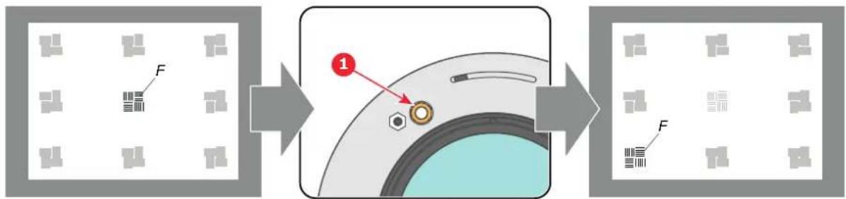
flowchart
graph LR
    A["Raw Material"] --> B["Step 1: Component 1"]
    B --> C["Final Product"]
Image 11-6
- Sharpen the image at the top right corner of the screen by turning the lower right Scheimpflug adjustment nut (reference 3 Image 11-7).
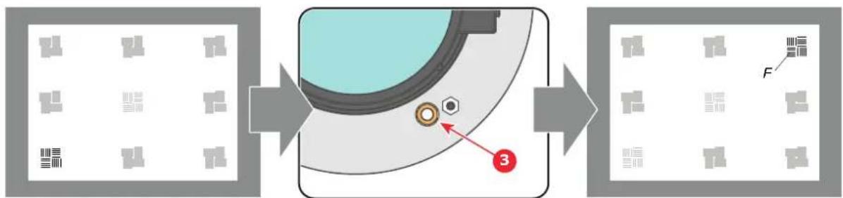
flowchart
graph LR
    A["Raw Material"] --> B["Mechanical Component"]
    B --> C["Final Product"]
    style A fill:#f9f,stroke:#333
    style B fill:#ccf,stroke:#333
    style C fill:#cfc,stroke:#333
Image 11-7
- Sharpen the image at the bottom right corner of the screen by turning the upper right Scheimpflug adjustment nut (reference 2 Image 11-8).
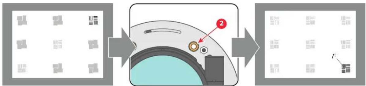
Image 11-8
- Optimize the focus of the projected image in the center of the screen using the motorized focus control (Local Keypad).
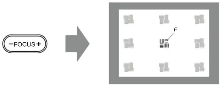
flowchart
graph LR
    A["-FOCUS+"] --> B["Grid of 10 gray rectangles"]
    B --> C["F"]
Image 11-9
- Repeat from step 1 until the projected focus pattern is as sharp as possible in the center, left, right, top and bottom of the screen.
- Proceed with the procedure "Fixation of the Lens Holder front plate", page 120.
11.3 Fixation of the Lens Holder front plate
When fixing the Lens Holder front plate
After performing the procedure for Scheimpflug adjustment or Back Focal Length adjustment the Lens Holder front plate must be secured in such a way that it doesn't disturb the result of the adjustment.
Required tools
• Allen wrench 3 mm
- Nut driver 10 mm
- Nut driver 13 mm
How to fix the Lens Holder front plate?
Start the fixation as follows (steps must be followed strictly):
- Project the Outline / Aspect test pattern (depending on projector type).
- Zoom the projected image until the edges of the projected test pattern matches with the edges of the projection screen.
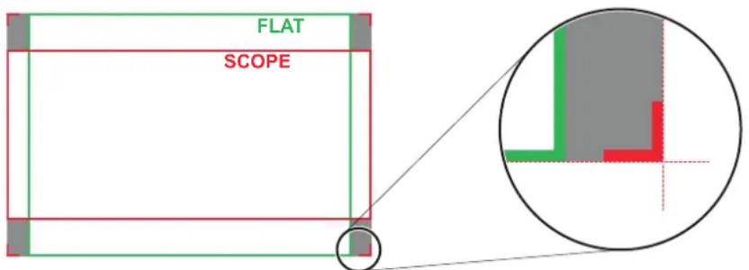
Image 11-10
- Turn in the three set screws indicated with reference 11 Image 11-11 without disturbing the projected image.
Tighten lightly. Do not turn in the set screw at the lower left of the Lens Holder!

Note: Ensure that the edges of the projected test pattern remain in place on the screen. Any movement of the image will affect the Scheimpflug adjustment.
- Fasten the lock nut (reference 21 Image 11-11) of the three set screws. Use a 10 mm nut driver. Ensure the image doesn't move.
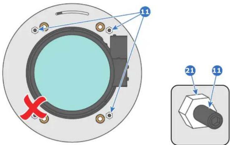
Image 11-11
- Gently turn (by hand) the Scheimpflug adjustment nut at the lower left of the Lens Holder (reference 4 Image 11-12) against the Lens Holder front plate without disturbing the projected image.
- Turn in the set screw at the lower left of the Lens Holder (reference 14 Image 11-12) without disturbing the projected image. Use a 3 mm Allen wrench.
Note: Ensure that the edges of the projected test pattern remain in place on the screen. Any movement of the image will affect the Scheimpflug adjustment.
Tip: Fasten the set screw and the Scheimpflug nut alternately, without disturbing the projected image, until the Scheimpflug nut and set screw are completely tightened.
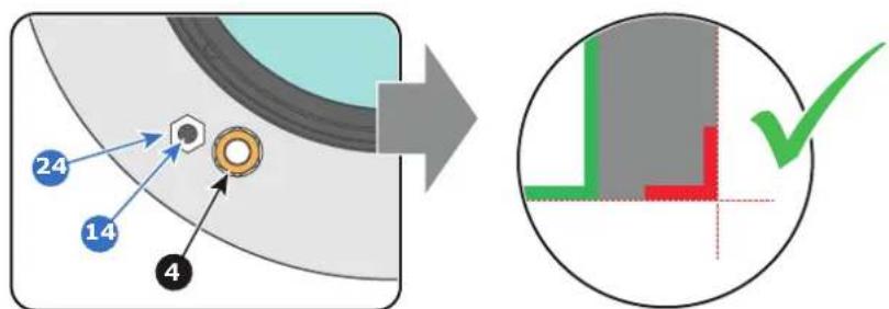
Image 11-12
- Fasten the lock nut at the lower left of the Lens Holder. Use a 10 mm nut driver.
11.4 Back Focal Length adjustment
When to adjust the Back Focal Length?
If a lens is used with a throw ratio suited for the application, (lens selection depends on projection distance and screen size) typically one would NEVER need to adjust the Back Focal Length of the projector.
A Back Focal Length adjustment is only required in case the Focus range of the installed lens does not capture the projection screen either for FLAT and/or for SCOPE. In other words, when it is impossible to focus the image on the screen for FLAT and/or for SCOPE. Note that the lenses for the Thor series series projector are varifocal. So, switching between FLAT and SCOPE (zoom action) requires a readjustment of the focus.
What is Back Focal Length adjustment?
Back Focal Length adjustment means moving the lens plane (Lp), thus the Lens Holder front plate, closer to or further from the DMD plane. The closer the lens plane to the DMD plane the further the focus range (Fr) of the lens will be.
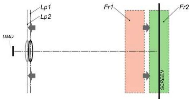
Image 11-13

Do not abuse the Back Focal Length adjustment of the Lens Holder. Neglecting this will result in loss of image quality because of the lens design. Cases requiring Back Focal Length adjustment normally indicate incorrect lens choice (throw ratio).
Required tools
• 10mm nut driver.
• 3mm Allen wrench.
• 13mm nut driver.
How to check the Back Focal Length?
- Ensure that the throw ratio of the installed lens matches with the requirements of the application (projection distance and screen size).
- Ensure that the correct lens parameters are activated. (See user guide of the "Communicator" chapter Installation > Advanced > Lens parameters)

Caution: Not using the correct lens parameters could result in lens damage.
- Perform a lens HOME & RETURN operation. (See user guide of the "Communicator" chapter Installation > Advanced > Lens parameters)
- Project the green focus test pattern. (screen file "no masking" or "no "crop")
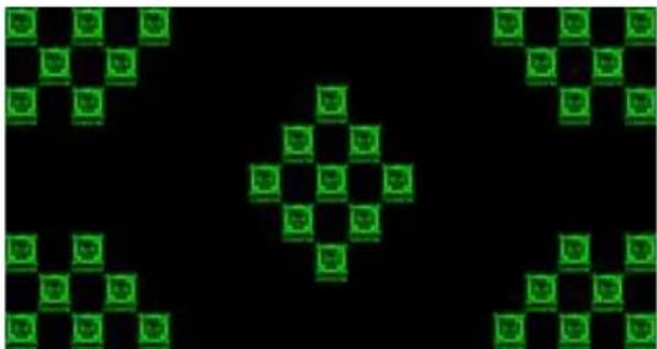
natural_image
Abstract geometric pattern with green square-like shapes on black background (no text or symbols)Image 11-14
- Zoom the lens for maximum image on the screen (WIDE).
- Is it possible to focus the center of the projected image?
▶ If yes, the Back Focal Length is OK.
▶ If no, the Back Focal Length needs realignment. Proceed with the next procedure.
How to adjust the Back Focal Length?
- Unlock and loosen the 4 set screws (reference 11 Image 11-15) of the Lens Holder by 1 centimeter. Use a 10mm nut driver for the lock nuts (reference 21 Image 11-15) and use a 3mm Allen wrench for the set screw.
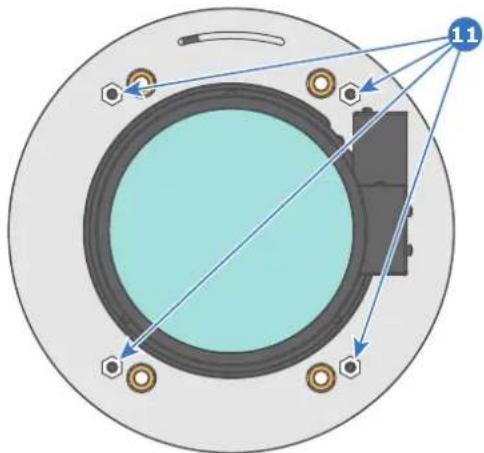
natural_image
Diagram of a circular mechanical component with internal components and directional arrows, no text or symbols present.Image 11-15
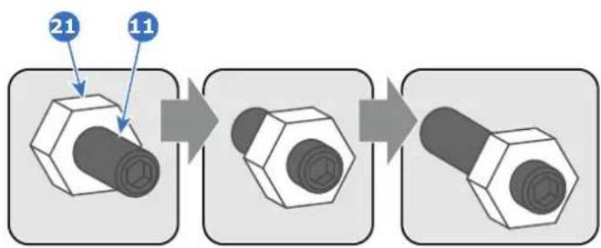
flowchart
graph LR
    A["Hexagon with two blue arrows labeled '21' and '11'"] --> B["Step 1"]
    B --> C["Step 2"]
    C --> D["Step 3"]
- Fully loosen the Scheimpflug nut at the lower left of the Lens Holder (reference 4 Image 11-16). Use a 13mm nut driver.
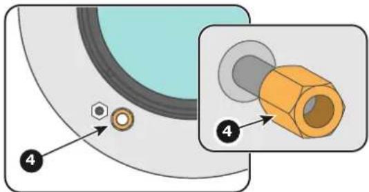
Image 11-16
- Turn the three Scheimpflug adjustment nuts, reference 1, 2 and 3 Image 11-17, until the front of the nut (reference 5 Image 11-17) is equally aligned with the front of the threaded rod (reference 6 Image 11-17). Use a 13mm nut driver.

Note: This is the nominal position of the Lens Holder.

Caution: Do not remove any of the Scheimpflug adjustment nuts completely from the threaded rod. Otherwise the lens holder front plate with lens will fall off.
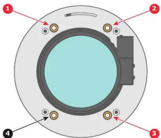
Image 11-17
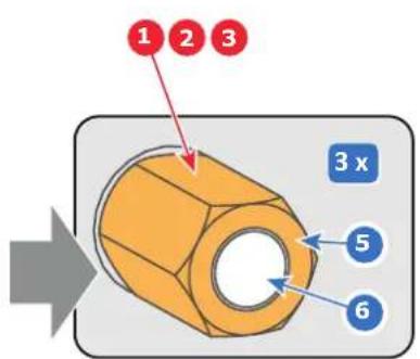
- Zoom the lens for maximum image on the screen (WIDE) and focus the center of the projected image using the motorized focus control (Local Keypad).
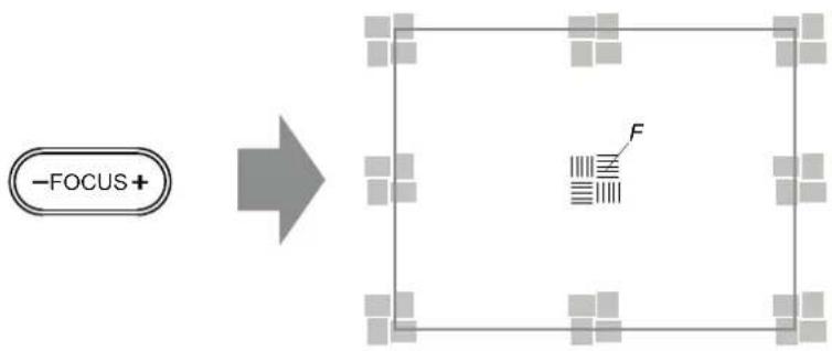
flowchart
graph LR
    A["-FOCUS+"] --> B["Rectangle with F symbol"]
    style A fill:#f9f,stroke:#333
    style B fill:#ccf,stroke:#333
Image 11-18
- Is it possible to focus the center of the projected image using the motorized focus control (Local Keypad)?
Ensure that the lens is zoomed for maximum image on the screen (WIDE).
▶ If yes, nominal position is good for sharp focus in the middle of the projected image. Proceed with step 6.
▶ If no, obtain the best possible focus in the center of the projected image using the motorized focus control and then turn the three Scheimpflug adjustment nuts, reference 1, 2 and 3 Image 11-19, equally in or out until the center of the projected image is sharp. Attention: Keep in mind the turning direction of the Scheimpflug adjustment nuts for further adjustment instructions in this procedure.
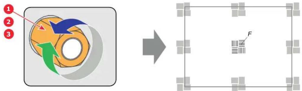
flowchart
graph LR
    A["Step 1: Red arrow"] --> B["Step 2: Blue arrow, Green arrow"]
    B --> C["Step 3: Arrow pointing to orange ring with blue arrow"]
    C --> D["→"]
    D --> E["Image: F barcode symbol"]
    style A fill:#f9f,stroke:#333
    style B fill:#ccf,stroke:#333
    style C fill:#cfc,stroke:#333
    style D fill:#fcc,stroke:#333
    style E fill:#ffc,stroke:#333
Image 11-19
- Zoom the lens for minimum image on the screen (TELE) and focus the center of the projected image using the motorized focus control (Local Keypad).
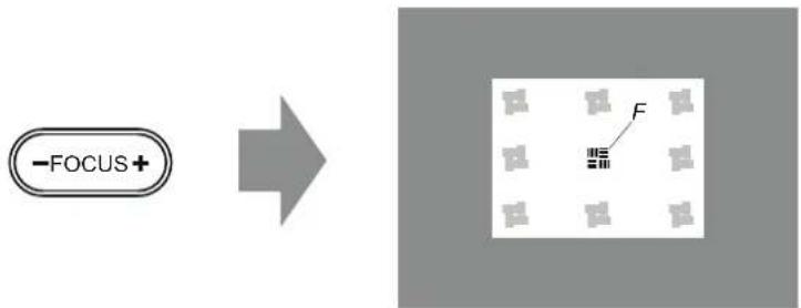
flowchart
graph LR
    A["-FOCUS+"] --> B["Grid with F"]
    style A fill:#f9f,stroke:#333
    style B fill:#ccf,stroke:#333
Image 11-20
- Is it possible to focus the center of the projected image using the motorized focus control (Local Keypad)?
Ensure that the lens is zoomed for minimum image on the screen (TELE).
▶ If yes, no further adjustment actions required. Proceed with step 8.
▶ If no, obtain the best possible focus in the center of the projected image using the motorized focus control and then turn the three Scheimpflug adjustment nuts, reference 1, 2 and 3 Image 11-21, equally in or out until the center of the projected image is sharp. Note: the same turning direction as in step 4 is applicable.
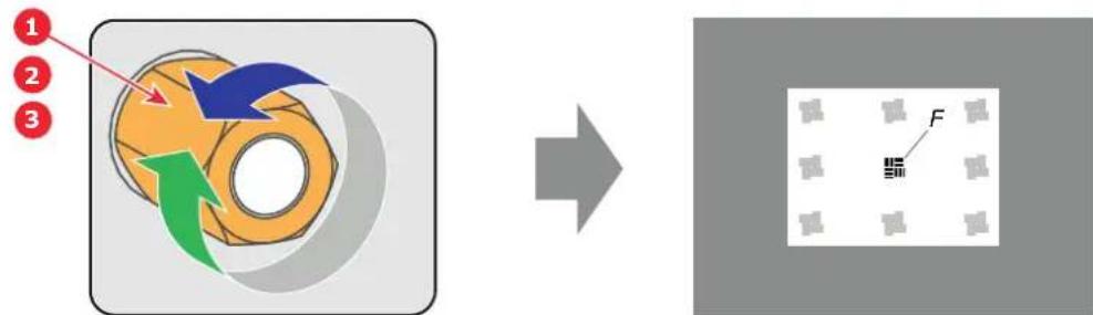
flowchart
graph LR
    A["Input 1: Red circle"] --> B["Process Step"]
    B --> C["Output F: Grey square with 'F' label"]
Image 11-21
- Check if it is possible to focus the center of the projected image using the motorized focus control (Local Keypad) for WIDE and for TELE.
If yes, the Back Focal Length is correctly adjusted.
▶ If no, repeat with step 4.
- Is the projected image in the corners as sharp as in the middle?
▶ If yes, proceed with the procedure "Fixation of the Lens Holder front plate", page 120.
▶ If no, Scheimpflug adjustment is required. See procedure "Scheimpflug adjustment", page 117, prior to fixate the Lens Holder front plate. CAUTION: Skip the action, in the Scheimpflug adjustment procedure, to turn the three Scheimpflug adjustment nuts until the front of the nut is equally aligned with the front of the threaded rod
Convergence
12
About this chapter
This chapter describes how to prepare the projector for convergence adjustment and how to adjust the convergence.
Overview
• Convergence controls
• Preparing for convergence adjustment
• Converging the red pattern onto the blue pattern
• Converging the green pattern onto the blue pattern
12.1 Convergence controls
Extended control knobs
As the DMD of the blue channel is not accessible in the projector, it remains fixed. Therefore the image of this DMD will be taken as reference. Red and green may be aligned onto blue when a small convergence drift is recognized. The red and green channels have pivot plates equipped with three extended control knobs for convergence adjustment. The control knobs are numbered from 1 to 6 and have the same color as the channel which they affect.
To access the control knobs the left side cover of the projector and a small cover plate in front of the control knobs have to be removed.
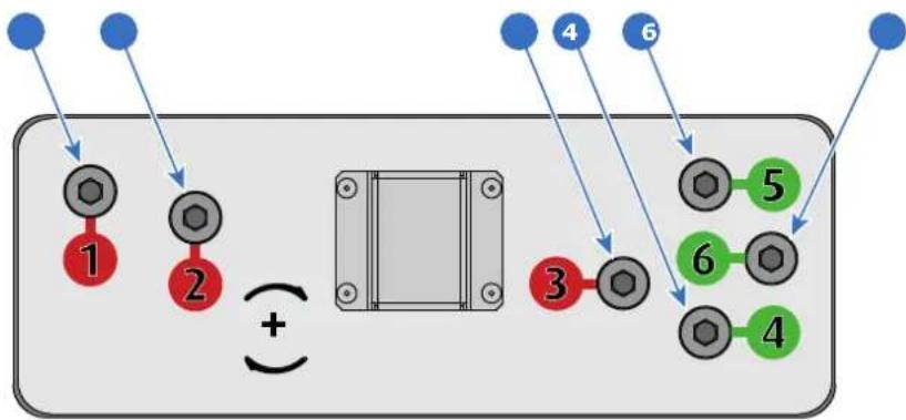
flowchart
graph TD
    A["1"] --> B["2"]
    C["3"] --> D["4"]
    E["4"] --> F["5"]
    G["6"] --> H["6"]
    I["6"] --> J["4"]
    style A fill:#f9f,stroke:#333
    style B fill:#ccf,stroke:#333
    style C fill:#cfc,stroke:#333
    style D fill:#fcc,stroke:#333
    style E fill:#cff,stroke:#333
    style F fill:#ffc,stroke:#333
    style G fill:#f9f,stroke:#333
    style H fill:#ccf,stroke:#333
    style I fill:#f9f,stroke:#333
    style J fill:#cfc,stroke:#333
Image 12-1
1 Red channel, control knob number 1.
2 Red channel, control knob number 2.
3 Red channel, control knob number 3.
4 Green channel, control knob number 4.
5 Green channel, control knob number 5.
6 Green channel, control knob number 6.
Convergence test pattern
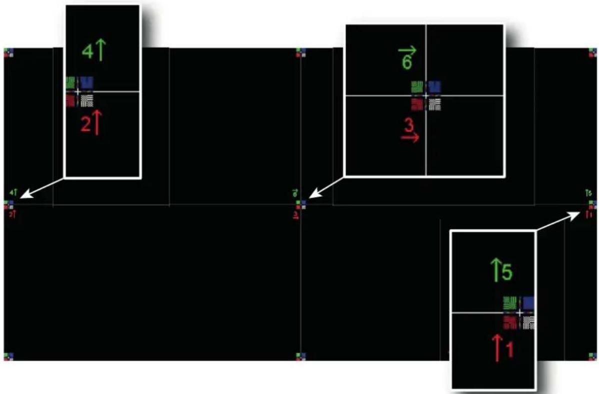
Image 12-2
The test pattern illustrated above is specifically designed for convergence purposes. The test pattern has three red arrows numbered from 1 to 3 and three green arrows numbered from 4 to 6. These numbers and colors correspond to those of the control knobs. Turning the control knob clockwise corresponds to the direction indicated on the screen.
Adjustment Range
Prevent damage to the system by limiting the amount/number of adjustment (s) made. Typically the convergence adjustments serve to correct a convergence fault of a few pixels at the most. Any convergence fault beyond this is considered grossly abnormal and likely indicates abuse or rough handling.
• Each adjustment allows for approximately 20 pixels (for 4K projectors) maximum displacement to either side of the nominal BLUE position.
- Rotation is limited to approximately +/- 10 pixels on the left screen flank and +/- 10 pixels on the right screen flank.
• One turn of a control knob relates to an approximately 10 pixels displacement on the screen.

CAUTION: The system does have an end of travel in either direction, but using excessive force may cause damage. Please handle gently.
Troubleshooting 'dead zone' of control knob
In rare cases it can happen that a control knob is loose in the perfect convergence position. This means that the nominal DMD position falls within a dead zone, where the mechanism changes from a pushing to a pulling function. This dead zone is due to inherent tolerances within the mechanism. If it so happens that the nominal position of an adjustment falls within this dead zone, it is preferable to continue screwing through the dead zone for another 2 turns. Then return to the required nominal position. The dead zone should now be displaced away from the required end position. The DMD is now securely held in the nominal position.
12.2 Preparing for convergence adjustment
What needs to be done?
To adjust the convergence of the projected image the control knobs of the convergence adjustment mechanism has to be made accessible and the projector must project the convergence test pattern.
Required tools
• Flat screwdriver 7 mm
• Allen wrench 3 mm
How to set up the projector for convergence adjustment?
- Remove the left side cover of the projector.
- Release the six screws (reference 1 Image 12-3) of the control knobs cover plate. Use a 3 mm Allen wrench.
- Remove the cover plate from the control knobs.
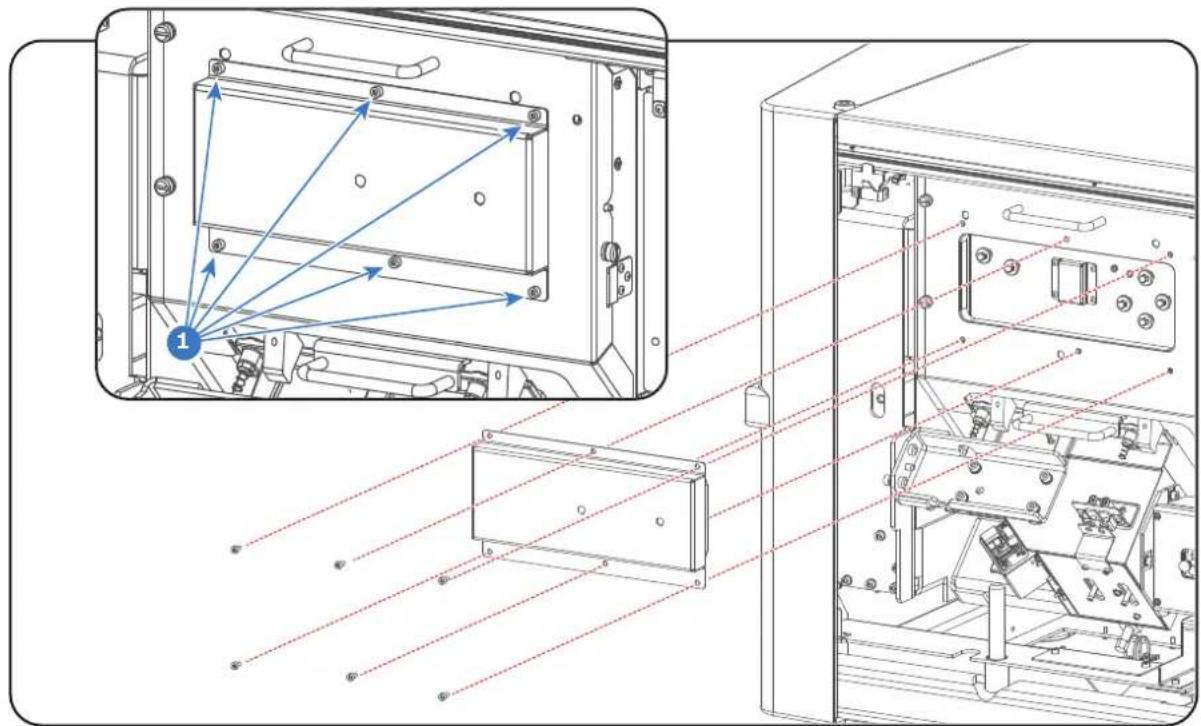
natural_image
Technical line drawing of an electronic device showing internal components and wiring (no text or symbols)Image 12-3
- Switch on the projector, activate the lasers and open the dowser.
- Select the convergence test pattern, which is illustrated below (Image 12-4). Use the communicator to activate the convergence test pattern.

Note: The convergence test pattern can NOT be activated via the PATTERN button on the Local Keypad.
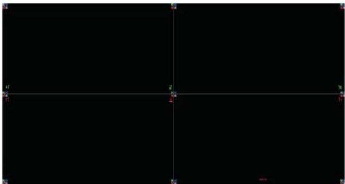
natural_image
Pure black background with no visible text, symbols, or identifiable objectsImage 12-4
- Let the projector warming up for 30 minutes before starting to adjust the convergence.
12.3 Converging the red pattern onto the blue pattern

This adjustment procedure assumes that the projector is prepared for convergence adjustment. See chapter "Preparing for convergence adjustment", page 130.
Required tools
5.5 mm nut driver or open-end wrench.
Converging the RED pattern onto the BLUE pattern
Start with aligning the RED pattern in the vertical direction (control knob 1 and 2) and then proceed with the horizontal direction (control knob 3)
- To translate the RED pattern vertically, slightly turn the red control knobs number 1 and 2. Turn both control knobs in equal increments.

Note: Note that a turn of a few degrees corresponds with one full pixel. Turning the control knob clockwise corresponds to the direction of the arrow of the test pattern.
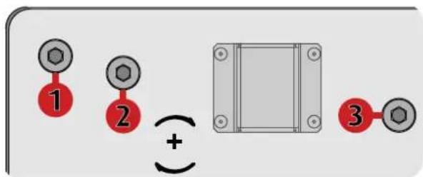
Image 12-5
- To translate the RED pattern horizontally, slightly turn the red control knob number 3.
- To rotate the RED pattern, slightly turn the red control knob number 1. If much rotation is required, slightly turn the red control knob number 2 in the opposite direction.

Note: Slight corrections of the RED pattern in vertical direction may be required after rotation.
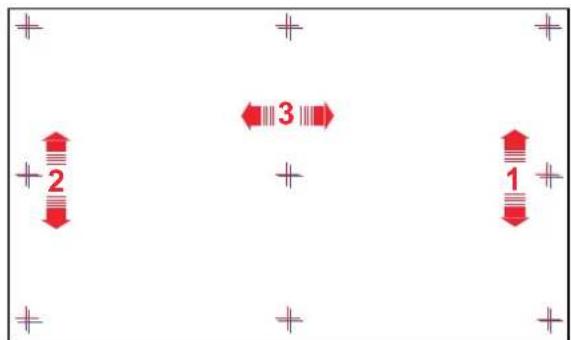
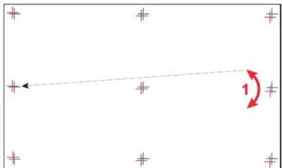
Image 12-6
- Repeat from step 1 until full coincidence is obtained of the RED pattern in the center, left and right of the projected image.
- To adjust the green pattern. See procedure "Converging the green pattern onto the blue pattern", page 132.
- When the red and green pattern are overall aligned with the blue reference pattern install the cover plate of the convergence control knobs and the projector left side cover.
12.4 Converging the green pattern onto the blue pattern

This adjustment procedure assumes that the projector is prepared for convergence adjustment. See chapter "Preparing for convergence adjustment", page 130.
Required tools
5.5 mm nut driver or open-end wrench.
Converging the GREEN pattern onto the BLUE pattern
Start with aligning the GREEN pattern in the vertical direction (control knob 4 and 5) and then pro with the horizontal direction (control knob 6)
- To translate the GREEN pattern vertically, slightly turn the green control knobs number 4 and 5. Turn both control knobs in equal increments.

Note: Note that a turn of a few degrees corresponds with one full pixel. Turning the control knob clockwise corresponds to the direction of the arrow of the test pattern.
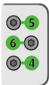
Image 12-7
- To translate the GREEN pattern horizontally, slightly turn the green control knob number 6.
- To rotate the GREEN pattern, slightly turn the green control knob number 4. If much rotation is required, slightly turn the green control knob number 5 in the opposite direction.

Note: Slight corrections of the GREEN pattern in vertical direction may be required after rotation.
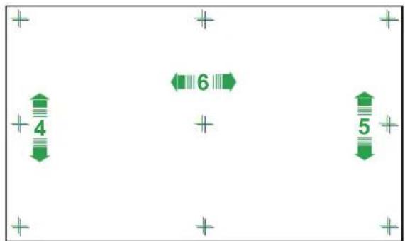
Image 12-8
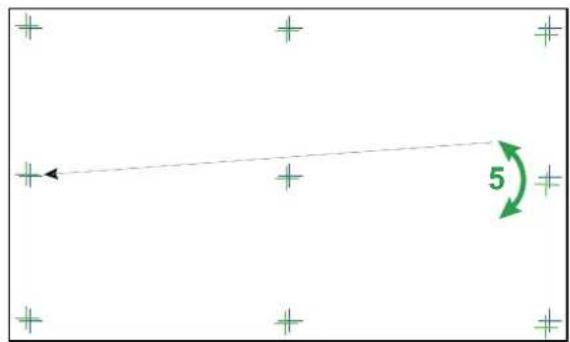
- Repeat from step 1 until full coincidence is obtained of the GREEN pattern in the center, left and right of the projected image.
- To adjust the red pattern. See procedure "Converging the red pattern onto the blue pattern", page 131.
- When the red and green pattern are overall aligned with the blue reference pattern install the cover plate of the convergence control knobs and the projector left side cover.
Calibration 13
About this chapter
This chapter describes the luminance and color calibration process for the Thor series. Where applicable references are made to the user guide of the Communicator for detailed menu navigation instructions. The first chapter describes the complete calibration process in chronological order.
Overview
• Calibration process
• White point calibration
• Color gamut calibration
• Luminance calibration
13.1 Calibration process
Calibration process overview
- Set the projector in the desired projection mode (laser mode):
2D
• 2D Rec. 2020
• Active Laser 3D (6P)
- External 3D
• External 3D Rec. 2020
• Passive Laser3D (Left eye)
• Passive Laser3D (Right eye)
-
Select desired aspect ratio by activating the correct lens file.
-
SCOPE format
-
FLAT format
-
Activate the uncorrected full white test pattern. Note that a test pattern does not have a format. It's always full screen. That's why the test pattern has to be activated after the format is chosen.
- Adjust projector light output slightly above the desired screen brightness. (screen brightness will slightly drop after calibration).
- White point calibration (Laser power calibration). Needs to be done per projection mode:
2D
- Laser3D : measure values for left eye and for right eye separately.
- with laser power Luminance balancing between left and right eye.
- External 3D : measure left and right together through the external 3D system.
For more info about white point calibration see chapter "White point calibration", page 137. The
Communicator contains a wizard for white point calibration. See user guide of the Communicator for detailed menu navigation instructions.
- Color gamut calibration. (electronic P7 correction). Measured values are saved in the Measured Color Gamut Data (MCGD) file. Needs to be done per format and per projection mode.
• FLAT:
- 2D → One MCGD file.
- Laser3D
- Left eye → One MCGD file.
Right eye → One MCGD file.
- External 3D
- Left eye → One MCGD file.
- Right eye → One MCGD file.
- SCOPE:
- 2D → One MCGD file.
-
Laser3D
-
Left eye → One MCGD file.
• Right eye → One MCGD file.
- External 3D
- Left eye → One MCGD file.
- Right eye → One MCGD file.
For more info about color gamut calibration see chapter "Color gamut calibration", page 139. The
Communicator contains a wizard for color gamut calibration. See user guide of the Communicator for detailed menu navigation instructions.
- Select target colors. The target colors are stored in the Target Color Gamut Data (TCGD) file. Several TCGD files are already available in the file system of the projector. Depending on the projector setup (2D, 3D, ...) the right TCGD file has to be activated. In case of luminance balancing (e.g. for 3D) a second TCGD file is derived from the selected TCDG file. Only the Y component in the second TCGD is modified to apply luminance balancing.
• 2D : → one TCGD file.
- Laser3D
- without electronic luminance balancing.
• Same TCGD for left and right eye.
- with electronic luminance balancing.
- Left eye → One TCGD file.
- Right eye → One TCGD file.
- External 3D
- without electronic luminance balancing.
• Same TCGD for left and right eye
- with electronic luminance balancing.
- Left eye → One TCGD file.
- Right eye → One TCGD file.
For detailed instructions on how to select target colors and how to apply luminance balancing see user guide of the Communicator.
8. Verify corrected colors.
For detailed instructions on how to verify corrected colors see user guide of the Communicator.
9. Luminance calibration.
For more info about luminance calibration see chapter "Luminance calibration", page 141.
- Arrange calibration files in macro. To apply correct color calibration it is important that the MCGD file(s) and matching TCGD file(s) are activated after that the INPUT file and PCF file are activated. For that it's recommended to create a macro where the files are loaded one by one in the right order:
a) First activate the INPUT file. Ensure that in case of 3D projection with the ICMP media player the color correction "Dual (separate eyes)" is selected in the INPUT file.
b) then activate the PCF file (PCF already contains plane 1 information),
c) then activate the MCGD and TCGD files of plane 1.
d) and in case of 3D activate the MCGD and TCGD files of plane 2.
For detailed instructions on how to create a macro see user guide of the Communicator.
13.2 White point calibration
What has to be done?
The projector uncorrected white point n (V has to be shifted towards the DCI white point T) coordinates of the DCI white point ( x = 0.314 ; y_0 = 0.351 ) are embedded in the projector software and cannot be changed. The coordinates of the projector uncorrected white point has to be measured and entered.
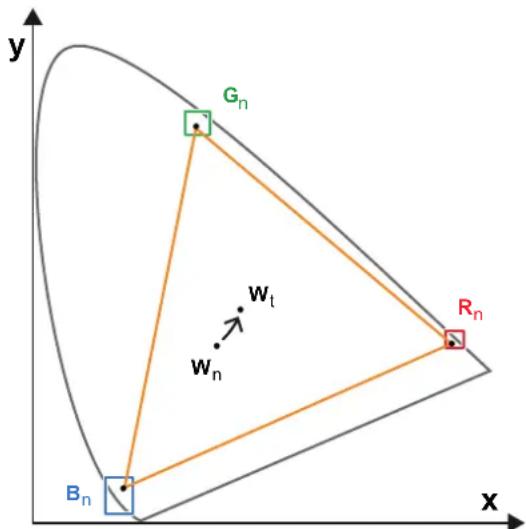
Image 13-1: Shifting projector 'white point' towards desired white point (laser power calibration)
The projector uncorrected white point can be defined by measuring the xy coordinates of the uncorrected primary colors (red, green, blue) and uncorrected full white separately.
The initial set of xy values stored in the projector for the uncorrected white point are the same as for DCI wh point. After white point calibration, the initial values are overwritten with the measured values.
Laser RGB correction
Based on the measured values the projector can balance the power of the lasers for Red Green and Blue to move the projector uncorrected white point towards the desired white point. This adjustment is called 'Laser RGB correction' or 'Laser power calibration'.
2D and 3D projector mode
The projector uncorrected white point is different for 2D projection, Laser3D projection and External 3D projection. Therefore, the projector uncorrected white point has to be measured and entered for each projection mode separately. Per projection mode one set of measured values are stored. Depending on the projection mode, the corresponding set is used for white point correction.
In case of 3D projection, the xy coordinates of uncorrected white has to be measured twice. Once through the left eye glass of the 3D goggles and once through the right eye glass.
Luminance balancing
In case of Laser3D projection, it is possible to correct difference in luminance between left and right. Scaling is applied from the strongest eye towards the weakest eye. Note that this is not possible for External 3D systems.
Required tools
- Spectroradiometer.
- Communicator.
White point calibration procedure:
- Setup the ambient light conditions as it should be during the play out of the movie. (e.g. only the stairs and emergency exit lighting is switched on).
Note: In an optimal setup less than 1% of light from any other source than the light from the projector should illuminate the screen.
- Set the projector in the desired projection mode 2D, Laser3D or External 3D. For detailed instructions see user guide of the Communicator.
- Configure the desired aspect ratio: e.g. FLAT or SCOPE (use most common aspect ratio). Do this by activating the correct LENS file. For detailed instructions see user guide of the Communicator.
- Project a none calibrated full white test pattern. For detailed instructions see user guide of the Communicator.
- Measure the reflected light from the center of the screen with a spectroradiometer. Position the spectroradiometer perpendicular to the screen in the auditorium sweet spot.
! Caution: Do not measure the light through the port window of the boot area!
- Adjust the light output of the projector slightly above the desired screen brightness. (screen brightness will slightly drop after calibration). Use the Communicator software to achieve that. Go to Installation > Illumination > Light output. For detailed instructions see user guide of the Communicator.
- Sequentially measure and enter the xy coordinates of the three primary colors (red, green, blue) and full white. Use therefore the "Laser white calibration" wizard in the Communicator. Go to Installation > Color calibration > Laser white calibration. For detailed instructions see user guide of the Communicator.
! Caution: Ensure that the correct projection mode is selected: 2D, Laser3D or External 3D.
Caution: In case of 3D measure the xy coordinates once through the left eye glass of the 3D goggles and once through the right eye glass.
The wizard will reset previous xy values of power calibration and automatically start with projecting uncorrected primary red. Once you have measured and entered the xy values for red, click on "next" and
repeat the measurement for green, blue and white. When finished the laser power levels are automatically corrected according to the entered xy values.
- In case of Laser3D apply Luminance balancing for the left and right eye. Do this by measuring the Y coordinates of full white through the left eye glass and through the right eye glass. Enter the measured values in Communicator to apply luminance balancing. For detailed instructions see user guide of the Communicator.

After white point calibration proceed immediately with color gamut calibration.
13.3 Color gamut calibration
Color Gamut
Color Gamut is the entire range of reproducible colors by a particular device such as a projector. The entire range of reproducible colors are typically defined so that horizontal and vertical directions describe saturation and luminance changes, respectively. When a color is "out of gamut," it is not possible to reach that color by the device.
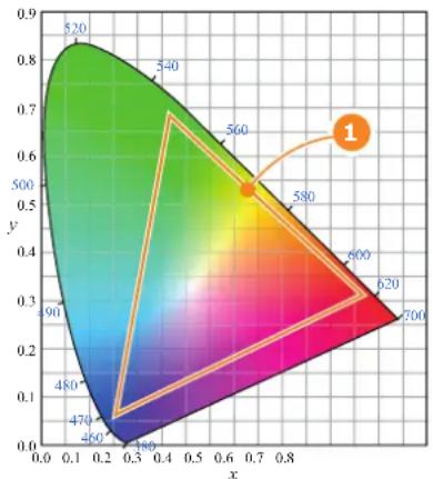
heatmap
| x | y | | ---- | ---- | | 0.1 | 0.9 | | 0.3 | 0.7 | | 0.5 | 0.5 | | 0.7 | 0.3 | | 0.9 | 0.1 |Image 13-2: Sample Chromaticity Diagram with Color Gamut of target device (1).
Why apply color correction?
During the post-production process of a film, a specific color space is applied. This color space is the Target Color Gamut Data (TCGD). All movie content operates under that gamut. To ensure that in the cinema theater the film is projected within the same color space as intended by the film industry, the color space of the projector has to be corrected accordingly.
What has to be done?
The color coordinates for the projected primary colors must be measured on the screen. The values can be different than those originally inside the projector due to reflection on the screen or due to the influence of the glass between the projection booth and the theatre and even the projected colors are different from setup to setup.
These measured color coordinates are references for the projector and will be entered so that the projector knows how its colors are projected on the screen. This reference measurement (MCGD), together with the delivered gamut file (TCGD) of the film will introduce a color correction so that the film will be projected with the desired color target.
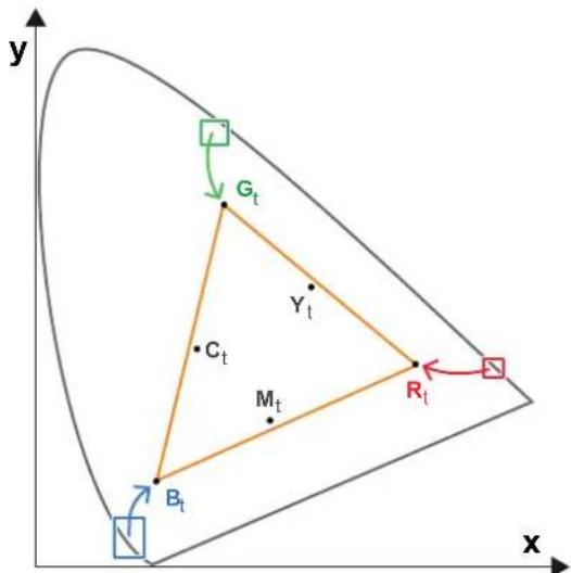
Image 13-3: Correction of native color gamut towards desired color gamut (electronic correction)
Electronic correction
The electronic correction adapts the native color gamut towards the desired (target) color gamut (e.g. DC28_DCI_Xenon.TCGD). This correction is introduced by the DMD drivers and is also called 'P7 correction'. The electronic correction takes place once the MCGD file of the projector is mapped with the TCGD file of the film
Influence of aspect ratio
The aspect ratio of the projected image could have a small influence upon the measured xy coordinates. Therefore, it's recommended to save the xy coordinates per aspect ratio in separate MCGD files.
3D color calibration
In case of 3D projection the uncorrected (native) Red, Green, Blue and White color coordinates of the projector has to be measured twice. Once through the left eye glass of the 3D goggles and once through the right eye glass.

CAUTION: Prior to start with color gamut calibration ensure that the white point calibration for the same projection mode (2D, Laser3D or External 3D) is finalized successfully. See chapter "White point calibration", page 137.
Required tools
- Spectroradiometer.
• Communicator.
Color gamut calibration procedure:
- Check if the white point calibration for the projection mode (2D, Laser3D or External 3D) of which you want to apply color gamut correction is done. If not see chapter "White point calibration", page 137.
- Setup the ambient light conditions as it should be during the play out of the movie. (e.g. only the stairs and emergency exit lighting is switched on).

Note: In an optimal setup less than 1% of light from any other source than the light from the projector should illuminate the screen.
- Sequentially measure and enter the xy coordinates of the three primary colors (red, green, blue) and full white. Use therefore the Communicator. Go to Installation > Color calibration > Measure native colors. For detailed instructions see user guide of the Communicator.

Caution: Ensure that the correct projection mode is selected: 2D, Laser3D or External 3D.
Caution: In case of 3D, measure the xy coordinates once through the left eye glass of the 3D goggles and once through the right eye glass.
Tip: When using the wizard for white point calibration you can immediately proceed with the electronic correction.
- Once all xy coordinates are measured and entered proceed by saving all measured values into a MCGD file.
Tip: Put in the MCGD file name the type of projection mode (2D, Laser3D, External 3D,...) and the aspect ratio (FLAT, SCOPE).
- Map the MCGD file with the TCGD file. Use for that the Communicator. Go to Installation > Color calibration > Select target colors. For detailed instructions see user guide of the Communicator.
- In addition you can check if the corrected colors complies. Use therefore the Communicator. Go to Installation > Color calibration > Verify corrected colors. For detailed instructions see user guide of the Communicator.
13.4 Luminance calibration
Screen Brightness

Screen Brightness, or how bright a screen will look, involves measuring the light reflected from its surface to our eyes. It takes into account the luminous flux (lumens) falling over its entire area (lux) and how reflective the surface of the screen is. It literally is a measure of the light bouncing off the screen. Luminance is measured in foot-lamberts. One foot-Lambert of luminance is equal to one lumen per square foot.
Why calibrating the Light Sensor?
The purpose of luminance calibration is to make a reference between the light measured by the projector built-in light sensor and the light reflected by the screen. This to tell the projector how much power the RGB lasers require to get the desired screen brightness (e.g. 14 ft-L).
Required tools
- Spectroradiometer.
- Communicator.
Light Sensor Calibration process
- Setup the ambient light conditions as it should be during the play out of the movie. (e.g. only the stairs and emergency exit lighting is switched on).
Note: In an optimal setup less than 1% of light from any other source than the light from the projector should illuminate the screen. - Project a none calibrated full white test pattern with the desired aspect ratio (e.g. FLAT).
Note: Per aspect ratio (FLAT, SCOPE, ...) the light sensor needs to be calibrated for optimal result. - Measure the reflected light from the center of the screen with a spectroradiometer. Position the spectroradiometer perpendicular to the screen in the auditorium sweet spot.
! Caution: Do not measure the light through the port window of the boot area! - Adjust the light output of the projector with the Communicator to obtain the desired screen brightness (e.g. 14 ft-L). Ssee user guide of the Communicator for detailed instructions.
- Create a Light Sensor Calibration file (LSC-file) based on the adjusted light output and projected aspect ratio. For detailed instructions see user guide of the Communicator.

Tip: Put the name of the aspect ratio in the file name. This will make it easier to recognize the file when needed. The LSC-file can be included in a 'macro' which execute several commands sequentially to setup the projector (and environment) to play a movie.
- Repeat this measurement process for other aspect ratios if applicable (e.g. SCOPE).

The US unit of luminance is the Foot-lambert or ft-L whereas the SI unit is Candela per Square Meter or cd/m 1 ft-L equals 3.426 cd/m nit (nt) is a non-SI name also used for this unit. 1 nt equals 1 cd/m The US unit Foot-lambert is the one typically used in cinema theater design and calibration.
Preventative maintenance actions
14
Maintenance program
The maintenance program is subdivided in time frames. The maintenance actions described in this chapter can be done by a trained projectionist. Note that there are also annually and 4 yearly maintenance actions (no included in this manual) which must be done by certified service personnel who are familiar with potential hazards of the product and all product safety checks. Contact your service partner for more information about maintenance services.
Overview
• 1 month maintenance actions
• 3 month maintenance actions
14.1 1 month maintenance actions
MAINTENANCE TYPE A (perform every month)

The 1 month maintenance actions, listed below, may be performed by a trained projectionist who is familiar with potential hazards associated with the product.
No. Maintenance action Remarks
| 1 | Check dust filters of the projector for dust and grease.Grease on the filter can build up after several months in an environment contaminated with greasy air. Note that areas where popcorn is consumed are subject to greasy air.If the filters are contaminated with dust than cleaning the filters with a vacuum cleaner should be sufficient.In case the filters feel greasy than the filters must be washed.Take into account that the time needed to dry the dust filters may be 24 hours or more. For that, it's recommended to have a second set of dust filters which can be used while cleaning the first set. | Replace damaged filters immediately.See procedures “Vacuum cleaning of the dust filters”, page 149, and “Washing and drying the dust filters”, page 149.To speed-up drying, allow the filter(s) to dry at 50°C max in a well ventilated room. |
| 2 | Check the surface of the lens output side for dust. (it is not needed to remove the lens from the projector). Only clean if necessary case dust is clearly visible upon the surface.Note: if the lens was removed from the projector, a manual “Lens Home & Return” action must be executed to calibrate the position of the lens in relation to the Lens Holder. This way the references of the existing 'lens files' remain valid.See user guide of the Communicator software. | |
| 3 | Check the porthole (both sides) for dust. Clean the porthole in case dust is clearly visible upon the surface. Use an optical cloth. | |
| 4 | Check the good working condition of the external safety interlock system (if installed). | Ensure that all safety signs are still in place. . |
| 5 | Check dust filters of the chillers for dust and grease. | To access the filters and cleaning instructions see documentation set of the chillers. |
14.2 3 month maintenance actions
MAINTENANCE TYPE B (perform every three months)

The 3 month maintenance actions, listed below, may be performed by a trained projectionist who is familiar with potential hazards associated with the product.
No. Maintenance action Remarks
| 1 Clean the housing of the projector. Removal overall dust | accumulation on projector covers. See cleaning instructions in this manual. |
| 2 Clean the housing of the chillers. Removal overall dust | accumulation on chiller covers. See documentation set of the chillers. |
| 3 Verify the internal clock of the ICMP with real time clock. Corrected needed. | Corrected ICMP version 1.2.1 is required.Communicator version 5.0 is required.See user guide of Communicator for detailed instructions. |
Maintenance procedures
15
About this chapter
This chapter describes several maintenance procedures for the projector.

WARNING: All procedures described in this chapter may only be performed by TRAINED PROJECTIONISTS or qualified SERVICE PERSONNEL.
Overview
- Check the dust filters
• Vacuum cleaning of the dust filters
• Washing and drying the dust filters - Cleaning the lens
• Cleaning the exterior of the projector
• Authorization to clear security warning on the projector
15.1 Check the dust filters
How to check the large dust filter?
- Unlatch and pivot the front cover door which contains the dust filters.

Note: In case there is insufficient space to pivot the front cover door 90 degrees pull out the small side panel from the front cover door assembly as illustrated below.
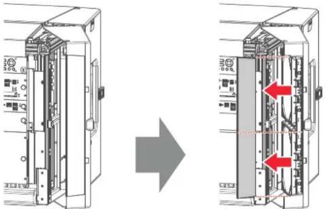
natural_image
Diagram showing two views of an industrial control unit with internal components and red arrows indicating internal connections (no text or symbols present)Image 15-1
- Detach the dust filters from the inner side of the front cover door. Do this by pushing the two latches (reference 1 Image 15-2) of the dust filter inwards.
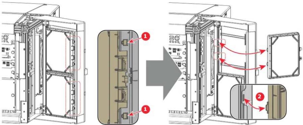
Image 15-2
- Check the "air in" side of the dust filter for dust and/or grease.
In case the filter is contaminated with grease wash and dry the dust filter. See cleaning procedure "Washing and drying the dust filters", page 149.
In case the filter contains dust but doesn't feel greasy then vacuum clean the dust filter. See procedure "Vacuum cleaning of the dust filters", page 149.

Note: Grease on the filter can build up after several months in an environment contaminated with greasy air. Note that areas where popcorn is consumed are subject to greasy air.

Tip: Take into account that the time needed to dry the dust filters may be 24 hours or more. For that, it's recommended to have a second set of dust filters which can be used while cleaning the first set.
- Attach the clean dust filters to the inner side of the front cover door. Ensure that both latches and both mounting lips (reference 1 and 2 Image 15-2) of the dust filters are engaged.
Caution: UNDER NO CIRCUMSTANCES SHOULD WET FILTERS BE INSTALLED BACK INTO THE PROJECTOR. THIS CAN HAVE SERIOUS SAFETY CONSEQUENCES AS WELL AS JEOPARDIZE INTERNAL COMPONENTS OF THE SYSTEM.
- Reinstall the small side panel (if removed, see Image 15-1) and close the front cover door.

The dust filter is cleanable. See cleaning procedure for correct cleaning and drying instructions.
15.2 Vacuum cleaning of the dust filters
When to vacuum clean the dust filters?
The dust filters of the projector should be checked every month. If the filters are contaminated with dust then cleaning the filters with a vacuum cleaner should be sufficient. In case the filters feel greasy these must be washed. See cleaning procedure “Vacuum cleaning of the dust filters”, page 149.

Grease on the filter can build up after several months in an environment contaminated with greasy air. Note that areas where popcorn is consumed are subject to greasy air.

This procedure assumes that the dust filters are removed from the projector.
Required tools
Vacuum cleaner with soft brush suction nozzle.
How to vacuum-clean the dust filter?
- Carefully vacuum the air inlet side of the dust filter. Use a vacuum cleaner with a soft brush suction nozzle. The air inlet side of the dust filter is the side which is surrounded with a glue edge.

Tip: Lightly tap the filter on its dusty side to expel heavy dust contamination.

Tip: Compressed air is also permitted to clean the filters but take care not to damage them.

Caution: Do not use compressed air inside the booth area. Bring the dust filters outside the building to blow off the dust.

Caution: Do not damage the dust filter. Replace damaged dust filters immediately.
15.3 Washing and drying the dust filters
About filter washing and drying
For environments where popcorn grease and such can contaminate the filters, Barco advises the client to purchase one extra set of filters to cover drying time, as well as taking following extra precautions and instructions pertaining to filter cleaning and drying.
Cleansing agent
To clean sticky, greasy dust filters we suggest usage of Sodium carbonate crystals (NO_3) . Sodium carbonate (Often called washing soda, soda crystals, or sal soda in the detergent section of stores) is widely used to effectively remove oil, grease, alcohol stains ... The product itself is relatively safe, sodium
carbonate is used in toothpastes and as a food additive (E500). Potential Hazards are described in the section "Safety precautions Hazardous Chemicals", page 17.
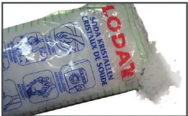
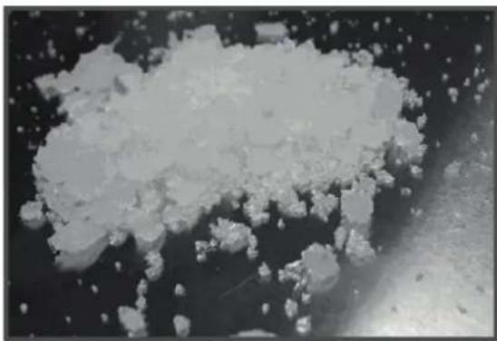
natural_image
Microscopic view of a granular material or particle cluster in a dark environment (no visible text or symbols)Image 15-3: Sodium carbonate crystals.

This cleaning procedure assumes that the filters are already removed from their slots.

Take into account that the time needed to dry the dust filters may be 24 hours or more. For that, it's recommended to have a second set of dust filters which can be used while cleaning the first set.
Required tools
- Bucket with hot water
• Sodium carbonate, 30 gram (handful) per liter hot water
How to wash and dry the dust filters?
- Make a solution with a ratio of 30 gram (a handful) sodium carbonate to 1 liter hot water.
- Soak the dust filters in the solution for 30 to 60 minutes. The grease should be dissolved after 1 hour.
- If the dust filter is still clogged repeat this procedure from step 1.
- Rinse the dust filters with clean water to flush all grease residue away.
- Shake out all excess liquid by repeatedly swinging the filter to-and-fro in a centrifugal action.
- Then allow the filters to dry thoroughly.

Note: Drying time of the dust filters can be up to 24h or more. Drying time can be shorter when being done in a well-ventilated area.

Tip: To speed-up drying, allow the filter(s) to dry at 50^ C max in a well ventilated room.

CAUTION: UNDER NO CIRCUMSTANCES SHOULD WET FILTERS BE INSTALLED BACK INTO THE PROJECTOR. THIS CAN HAVE SERIOUS SAFETY CONSEQUENCES AS WELL AS JEOPARDIZE THE INTERNAL OPTICS OF THE SYSTEM.

CAUTION: Do not install/use damaged dust filters. Replace damaged dust filters immediately with new dust filters of the same type. See https://my.barco.com for the correct replacement part.
15.4 Cleaning the lens

WARNING: Make sure that the lasers are switched OFF before performing this procedure

To minimize the possibility of damage to optical coatings, or scratches to lens surfaces follow the cleaning procedure as described here precisely.
Required tools
- Compressed air.
- Clean Toraysee® cloth or any micro fiber lens cleaning cloth.
- Clean cotton cloth.
Required parts
Lens cleaner (e.g. Carl Zeiss lens cleaner or Purasol® or any water-based lens cleaner)
How to clean the lens?
- Blow off dust with clean compressed air (or pressurized air). cans
- Clean with lens cleaner together with a clean lens cleaning cloth to remove the dust and contamination. Use big wipes in one single direction.

Warning: Do not wipe back and forwards across the lens surface as this tends to grind dirt into the coating.
-
Use a dry lens cleaning cloth to remove left liquid or stripes. Polish with small circles.
-
If there are still fingerprints on the surface, wipe them off with lens cleaner together with a clean lens cleaning cloth. Polish again with a dry one.

If smears occur when cleaning lenses, replace the cloth. Smears are the first indication of a dirty cloth.
15.5 Cleaning the exterior of the projector
How to clean the exterior of the projector?
- Switch off the projector and unplug the projector from the mains power net.
- Clean the housing of the projector with a damp cloth. Stubborn stains may be removed with a cloth lightly dampened with a mild detergent solution.
15.6 Authorization to clear security warning on the projector
When is an authorization required to clear the security warning?
If a module has been removed or if the sealed compartment has been opened, an authorization will be required to clear the security warning.
Required tools
Authorization pin code.
Authorization procedure to clear security warning
- Ensure that all modules are properly installed.
-
Start up the projector (Operational mode).
-
Initiate authorization by pushing the Key button on the Local Keypad:

The color of the backlight of the Numeric keys 1 to 6 of the Local Keypad changes to yellow.
- Enter pin code within 5 seconds.
- In case no keys are pressed, the color of the backlight of the Numeric keys 1 to 6 changes back to its original color. Authorization procedure is aborted.
- When code is entered then the backlight of the Key button lit up: - white in case of a service door tamper. (check if all covers are correctly installed) - red in case of an insertion tamper. (check if the ICMP is correctly installed) - green in case all tamper events are cleared.

Each attempt to clear the security warning and its result (successfully or unsuccessfully) is logged inside the projector.
Removal and installation of the projector covers
16

WARNING: Switch off the projector prior to opening or removing the projector covers, unless otherwise specified in the procedure.
Overview
- Opening the front and rear cover doors
- Removal of the top cover
• Removal of the side covers
16.1 Opening the front and rear cover doors

This procedure assumes that the lens is removed and that the hoses are disconnected from the projector. This procedure is applicable for all four cover doors.

To access the thumbscrews of the top cover it is sufficient to open de cover doors a few centimeters. In this case it's not needed to remove the lens and to disconnect the hoses.
Required tools
No tools required.
Open cover doors
- Unlatch (reference 1 Image 16-1) and pivot the plastic cover door.
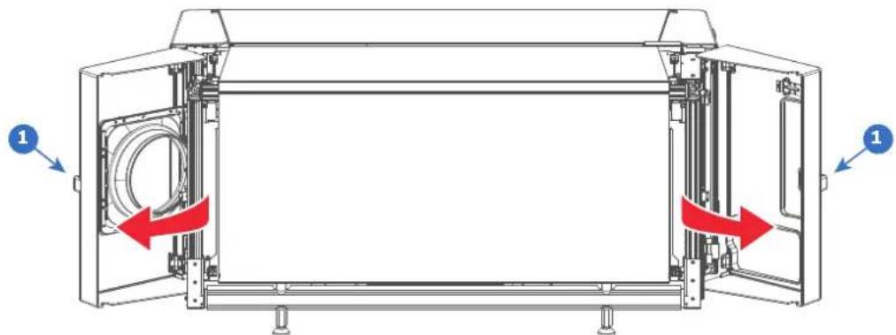
natural_image
Technical diagram of a mechanical device with open and closed sections, showing internal components and red directional arrows indicating motion (no text or symbols)Image 16-1
16.2 Removal of the top cover

The illustrations in this procedure are based on the top-left cover. Nevertheless, the same procedure is applicable for the top-right cover as well.
Required tools
Flat screwdriver 7 mm
How to remove a top cover?
-
Unlatch and pivot the front and rear plastic cover doors a few centimeters. This to gain access to the two thumbscrews of the top cover. See procedure "Opening the front and rear cover doors", page 154.
-
Loosen the two captive thumbscrews of the top cover (reference 2 Image 16-2).
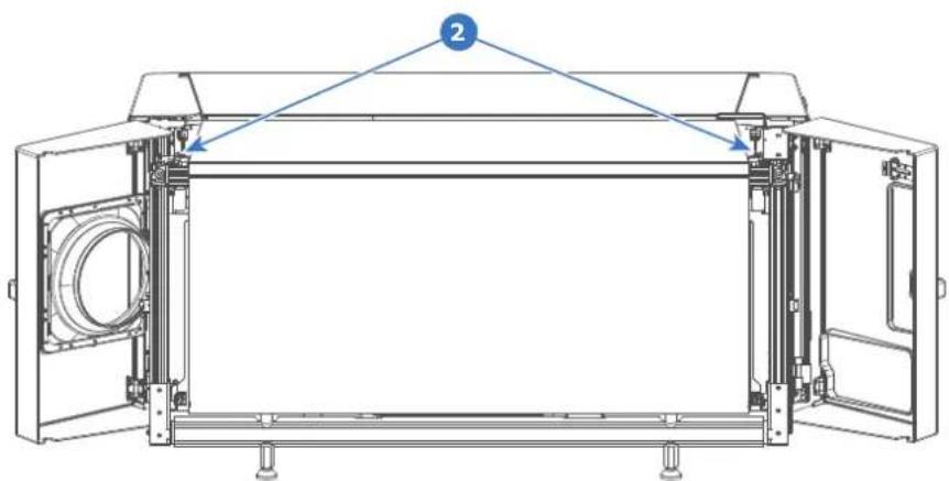
natural_image
Technical line drawing of a mechanical assembly with no visible text or symbolsImage 16-2
- Slide the top cover in horizontal direction a few centimeters away from the center of the projector (this to unhook), then remove it from the projector.
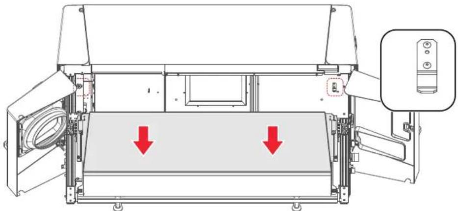
natural_image
Technical line drawing of a mechanical device with two red arrows indicating downward motion, no text or symbols present.Image 16-3
16.3 Removal of the side covers

The illustrations in this procedure are based on the left-side cover. Nevertheless, the same procedure is applicable for the right-side cover as well.
Required tools
• Flat screwdriver 7 mm
• Allen wrench 3 mm
How to remove a side cover?
- Unlatch and pivot the front and rear plastic cover doors a few centimeters. This to gain access to the two thumbscrews of the top cover and the side cover. See procedure "Opening the front and rear cover doors", page 154.

Note: The side cover is partially captured by the top cover and the front and rear plastic cover doors. For that, both cover doors have to be (partially) opened first.
- Remove the top cover or at least loosen the two captive thumbscrews of the top cover. See procedure "Removal of the top cover", page 154.

Tip: It's not needed to remove the top cover completely away from the projector to remove the side cover.
Removal and installation of the projector covers
- Loosen the two captive thumbscrews of the side cover (reference 3 Image 16-4).
- Remove the two screws located at the middle bottom of the side cover (reference 4Image 16-4). Use a 3 mm Allen wrench.
- Lift up the side cover about two centimeters and then remove it from the projector.
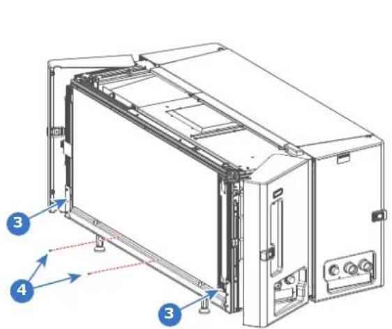
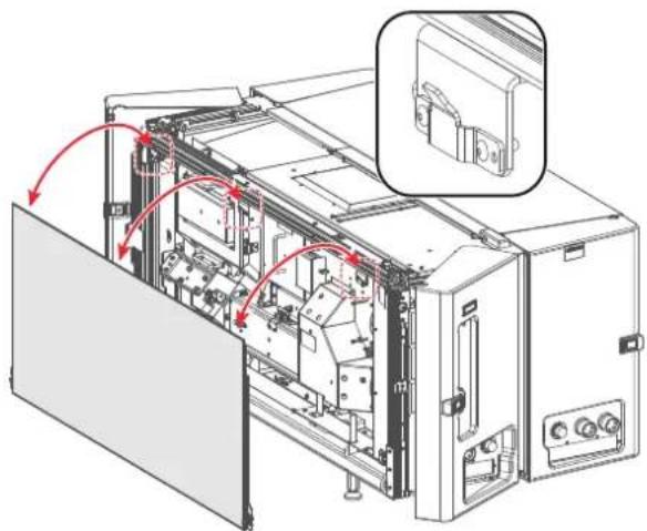
natural_image
Technical line drawing of an internal machine or enclosure with red arrows indicating motion or assembly, no visible text or symbols.Image 16-4
Specifications
A
About this chapter
This chapter gives an overview of the specification of your Thor series projector as well as the dimensions and the center of gravity.
Overview
• Specifications of the Thor
• Specifications of the Thor+
• Specifications of the ICMP
• Specifications of the ICMP-X
• Dimensions of the Thor series projector
• Technical Regulations
A.1 Specifications of the Thor
Specifications
| Projector type Three chip DLP | |
| Technology 3 x 1.38" DMD ^TM | |
| Resolution 4,096 x 2,160 (4K) | |
| Aspect ratio 1.89:1 | |
| Light source 6P RGB Laser | |
| Light source lifetime 30,000 Hours or moreReplaceable illumination | |
| Light output Up to 15,000 ANSI lumens | |
| CLO (constant light output) Yes | |
| Contrast ratio 6,000:1 Sequential1,000:1 ANSI w/High Contrast Lens | |
| Brightness uniformity 80% at sides75% at corners | |
| Lens range 4K-VHC LNS (1.13 - 1.72:1)4K-VHC LNS (1.35 - 1.86:1)4K-VHC LNS (1.46 - 2.10:1)4K-VHC LNS (1.65 - 2.60:1)4K-VHC LNS (2.00 - 3.35:1)DC4K HC (1.35 - 1.86:1)DC4K HC (1.46 - 2.10:1)DC4K HC (1.65 - 2.60:1)DC4K HC (2.00 - 3.35:1) | |
| Optical lens shift | Up to 25% vertical lens shift & up to 15% horizontal lens shiftMotorized zoom, focus, shutter and lens shift |
| Tilt | 20° Forwards5° Backwards |
| Optical dowser | Yes |
| Color correction | P7 |
| Color gamut | REC2020 |
| Image processing | Alchemy - Integrated Cinema Media Processor (ICMP) |
| WARP | N/A |
| Orientation | Pedestal / Table Top |
| Network connection | 10/100 Ethernet via RJ45 connection |
| Software tools | Barco Communicator |
| Integrated web server | No |
| HDR | HDR10 |
| 3D | Color3D (Barco Laser3D): Native 6-primary color-3D system. Only requires color filter glasses (Dolby3D glasses cannot be reused)Active glasses systems |
| Polarization recuperation systems | |
| Inputs Barco Alchemy ICMP | included in the projector:2 x HDMI2.0a (up to 4K 2D 60fps)2 x 3G-SDI inputs16 x AES/EBU audio channels (2 x RJ45)8 x GPI, 8x GPO (4 x RJ45)2 x Gbe for content connectivity & ingest2 x front-accessible USB 3.0 for fast ingest2 x front-accessible USB 2.0DCI 4K 2D up to 60fps*DCI 4K 3D (24 or 30fps per eye)*DCI High Frame Rates 2K 3D up to 120fps (60fps per eye)JPEG 2000 bit-rates up to 625 MbpsMPEG-2 (4:2:0 and 4:2:2 up to 60fps) |
| Input resolutions VGA up to 4K (4,096 x 2,160) @ 120Hz | |
| Integrated storage 3.9TB effective storage (RAID-5)via 3 x 2TB Hot-swappable 2.5" hard-drives | |
| Control RS232, TCP/IP, 8 x | GPIO |
| Power requirements Projector:Y connection: 200-240V / 346-415V 50-60Hz 16A 3W+N+PEPower cord size range: 4 sq mm to 6 sq mm, 10AWG to 8AWGCircuit breaker range: 25A to 40ADelta connection: 200-240V 3W+PE 28A 50-60HzPower cord size: 6 sq mm, 8AWGCircuit breaker: 40AChiller:Y connection: 230/400V 3W+N+PE 16A, 2.5 sq mmDelta connection: 208V / 3W+PEMax. 16A per phase | |
| Power consumption Projector (Full Laser Power):3.5 kW (2D or Polarization 3D)2.0 kW (Barco Laser3D - 6P)Chiller (Full Laser Power):2.0 kW (2D or Polarization 3D)1.6 kW (Barco Laser3D - 6P) | |
| Noise level (typical at 25°CProjector (w/Chiller):77°F) | Projector (w/Chiller):68 dB(A) - MaxProjector (w/o Chiller):52db(A) |
| Operating temperature 10 to 30 °C Max. (sea Level) | |
| Operational humidity 75% Max. (projector and chiller) | |
| BTU per hour 18,500 BTU/h | |
| Airflow requirements Air Inlet (from Rear w/Feet Down): TBCExhaust (from Rear w/Feet Down): TBC | |
| Exhaust airflow TDB | |
| Dimensions (WxLxH) Projector: | |
| 744 x 1,445 x 706 mm (w/Feet) (excludes lens)29.3 x 56.9 x 27.8 in. (w/Feet) (excludes lens)Chiller:701 x 701 x 800 mm27.6 x 27.6 x 31.5 in. | |
| Weight Projector: 200 kg / ~440 lbs (excludes lens)Chiller: ~115 kg / ~250 lbs | |
| Shipping Dimensions 1,780 | x 1,320 x 1,020 mm excludes lens - packaged separately)70.1 x 52.0 x 40.2 in. (excludes lens - packaged separately) |
| Shipping weight 307 kg / 677 lbs (excludes lens - packaged separately) | |
| Storage temperature TBC | |
| Storage humidity TBC | |
| Standard accessories TBC | |
| Certifications CE; ETL/UL/FCC, CCC | |
| Warranty Limited 2 years parts and labor Extendable up to 5 years | |
| Safety requirements Class | 1, Risk Group 3 |
| * Firmware upgradable | Please contact an authorized Barco representative for details |
A.2 Specifications of the Thor+
Specifications
| Projector type | Three chip DLP |
| Technology | 3 x 1.38" DMDTM |
| Resolution | 4,096 x 2,160 (4K) |
| Aspect ratio | 1.89:1 |
| Light source | 6P RGB Laser |
| Light source lifetime | 30,000 Hours or moreReplaceable illumination |
| Light output | Up to 32,000 ANSI lumens |
| CLO (constant light output) | Yes |
| Contrast ratio | 6,000:1 Sequential1,100:1 ANSI w/High Contrast Lens |
| Brightness uniformity | 80% at sides75% at corners |
| Lens range | 4K-VHC LNS (1.13 - 1.72:1)4K-VHC LNS (1.35 - 1.86:1)4K-VHC LNS (1.46 - 2.10:1)4K-VHC LNS (1.65 - 2.60:1)4K-VHC LNS (2.00 - 3.35:1)DC4K HC (1.35 - 1.86:1)DC4K HC (1.46 - 2.10:1)DC4K HC (1.65 - 2.60:1)DC4K HC (2.00 - 3.35:1) |
| Optical lens shift Up to 25% vertical lens shift & up to 15% horizontal lens shiftMotorized zoom, focus, shutter and lens shift | |
| Tilt 20° Forwards | 5° Backwards |
| Optical dowser Yes | |
| Color correction P7 | |
| Color gamut REC2020 | |
| Image processing Alchemy - Integrated Cinema Media Processor (ICMP) | |
| WARP N/A | |
| Orientation Pedestal / Table | Top |
| Network connection 10/100 | Ethernet via RJ45 connection |
| Software tools Barco Communicator | |
| Integrated web server | No |
| HDR | HDR10 |
| 3D | Color3D (Barco Laser3D): Native 6-primary color-3D system. Only requires color filter glasses (Dolby3D glasses cannot be reused)Active glasses systemsPolarization recuperation systems |
| Inputs Barco Alchemy ICMP | included in the projector:2 x HDMI2.0a (up to 4K 2D 60fps)2 x 3G-SDI inputs16 x AES/EBU audio channels (2 x RJ45)8 x GPI, 8 x GPO (4 x RJ45)2 x Gbe for content connectivity & ingest2 x front-accessible USB 3.0 for fast ingest2 x front-accessible USB 2.0DCI 4K 2D up to 60fps*DCI 4K 3D (24 or 30fps per eye)*DCI High Frame Rates 2K 3D up to 120fps (60fps per eye)JPEG 2000 bit-rates up to 625 MbpsMPEG-2 (4:2:0 and 4:2:2 up to 60fps) |
| Input resolutions | VGA up to 4K (4,096 x 2,160) @ 120Hz |
| Integrated storage | 3.9TB effective storage (RAID-5)via 3 x 2TB Hot-swappable 2.5" hard-drives |
| Control | RS232, TCP/IP, 8 x GPIO |
| Power requirements | Projector:Y connection: 200-240V / 346-415V 50-60Hz 16A 3W+N+PEPower cord size range: 4 sq mm to 6 sq mm, 10AWG to 8AWGCircuit breaker range: 25A to 40ADelta connection: 200-240V 3W+PE 28A 50-60HzPower cord size: 6 sq mm, 8AWGCircuit breaker: 40AChillers (each):Y connection: 230/400V 3W+N+PE 16A 2.5 sq mmDelta connection: 208V / 3W+PEMax. 16A per phase |
| Power consumption Projector (Full Laser Power):6.7 kW (2D or Polarization 3D)3.6 kW (Barco Laser3D - 6P)Chillers (each) (Full Laser Power):3.0 kW (2D or Polarization 3D)2.5 kW (Barco Laser3D - 6P) | |
| Noise level (typical at 25°CProjector (w/Chillers):77dB(A) - Max fan speed (start up phase)57dB(A) - Stable stateProjector (w/o Chillers):52db(A) | |
| Operating temperature 10 to 30 °C Max. (sea Level) | |
| Operational humidity 75% Max. (projector and chillers) | |
| BTU per hour 32,150 BTU/h | |
| Airflow requirements Air Inlet (from Rear w/Feet Down): TBCExhaust (from Rear w/Feet Down): TBC | |
| Exhaust airflow TDB | |
| Dimensions (WxLxH) Projector:744 x 1,445 x 706 mm29.3 x 56.9 x 27.8 in. (w/Feet) (excludes lens)2 x Chillers (each):701 x 701 x 800 mm27.6 x 27.6 x 31.5 in. | |
| Weight Projector: 235 kg / ~520lbs (excludes lens)2 x Chillers (each): ~115 kg / ~250 lbs | |
| Shipping Dimensions TBC (excludes lens - packaged separately) | |
| Shipping weight TBC (excludes lens - packaged separately) | |
| Storage temperature TBC | |
| Storage humidity TBC | |
| Standard accessories TBC | |
| Certifications CE; ETL/UL/FCC, CCC | |
| Warranty | Limited 2 years parts and laborExtendable up to 5 years |
| Safety requirements | Class 1, Risk Group 3 |
| * | Firmware upgradablePlease contact an authorized Barco representative for details |
A.3 Specifications of the ICMP
Specifications
| Integrated Cinema Media Processor | DCI 4K 2D up to 60fpsDCI 4K 3D (24 or 30 fps per eye)DCI High Frame Rates 2K 3D up to 120fps (60fps per eye)JPEG 2000 bit-rates up to 625MbpsDual-channel color-correctionMPEG-2 (4:2:0 and 4:2:2 up to 60fps)2x HDMI2.0a (up to 4K 2D 60fps)2x 3G-SDI inputs16x AES/EBU audio channels (2x RJ45)8x GPI, 8x GPO (4x RJ45)2x Gbe for content connectivity & ingest2x front-accessible USB 3.0 for fast ingest2x front-accessible USB 2.0Video and audio watermarking: Civolution NexGuardClosed captioning devices: Support for SMPTE 430-10Streaming of Live IP content |
| Barco Web Commander Projector dashboardProjector control boardShow player/editor/schedulerAutomation, 3D, IngestSmart projector statusVia HTML5 web browsers including iOS & Android tabletsCompatible with free Barco CineMate iOS & Android app | |
| Barco Commander (for touch panel controller) | Projector control boardShow Player/Editor/SchedulerAutomation, 3D, ingestDynamic DCP playlists & intermissionSmart projector status |
| Barco Communicator Projector installation & configurationProjector update & maintenanceBarco CineMate App (iOS & Android) - free | |
| Integrated storage 2TB effective storage (RAID-5) / 3x 1TB Hot-swappable 2.5" hard-drives4TB effective storage (RAID-5) / 3x 2TB Hot-swappable 2.5" hard-drives | |
| Options ICMP License for HDMI2.0 HDRICMP License for Live IP | |
| Compatibility Barco Alchemy is supported by the following Theater Management System (TMS) brands: AAM Screenwriter, Ymagis Melody, CFG-Barco, Unique RosettaBridge, ADDE, CinéDigital Manager, GDC, Proyecson, Real Image, Sony, Hollywoodsoftware/Comscore TCC, KinotonBarco Alchemy is supported by 4DX Experience | |
A.4 Specifications of the ICMP-X
Specifications
| Integrated Cinema Media Processor | DCI 4K 2D up to 60fpsDCI 4K 3D (24 or 30 fps per eye)DCI High Frame Rates 2K 3D up to 120fps (60fps per eye)JPEG 2000 bit-rates up to 625MbpsDual-channel color-correctionMPEG-2 (4:2:0 and 4:2:2 up to 60fps)2x HDMI2.0a (up to 4K 2D 60fps)2x 3G-SDI inputs16x AES/EBU audio channels (2x RJ45)8x GPI, 8x GPO (4x RJ45)2x Gbe for content connectivity & ingest2x front-accessible USB 3.0 for fast ingest2x front-accessible USB 2.0Video and audio watermarking: Civolution NexGuardClosed captioning devices: Support for SMPTE 430-10Streaming of Live IP content |
| Barco Web Commander | Projector dashboardProjector control boardShow player/editor/schedulerAutomation, 3D, IngestSmart projector statusVia HTML5 web browsers including iOS & Android tabletsCompatible with free Barco CineMate iOS & Android app |
| Barco Commander (for touch panel controller) | Projector control boardShow Player/Editor/SchedulerAutomation, 3D, ingestDynamic DCP playlists & intermissionSmart projector status |
| Barco (Web) Communicator | Projector installation & configurationProjector update & maintenanceBarco CineMate App (iOS & Android) - free |
| Integrated storage 2TB effective storage (RAID-5) / 3x 1TB Hot-swappable 2.5" hard-drives4TB effective storage (RAID-5) / 3x 2TB Hot-swappable 2.5" hard-drives8TB effective storage (RAID-5) / 3x 4TB Hot-swappable 2.5" solid state drives | |
| Options ICMP License for H | DMI2.0 HDRICMP License for Live IP |
| Compatibility Barco Alchemy | is supported by the following Theater Management System (TMS) brands: AAM Screenwriter, Ymagis Melody, CFG-Barco, Unique RosettaBridge, ADDE, CinéDigital Manager, GDC, Proyecson, Real Image, Sony, Hollywoodsoftware/Comscore TCC, KinotonBarco Alchemy is supported by 4DX Experience |
A.5 Dimensions of the Thor series projector
Dimensions
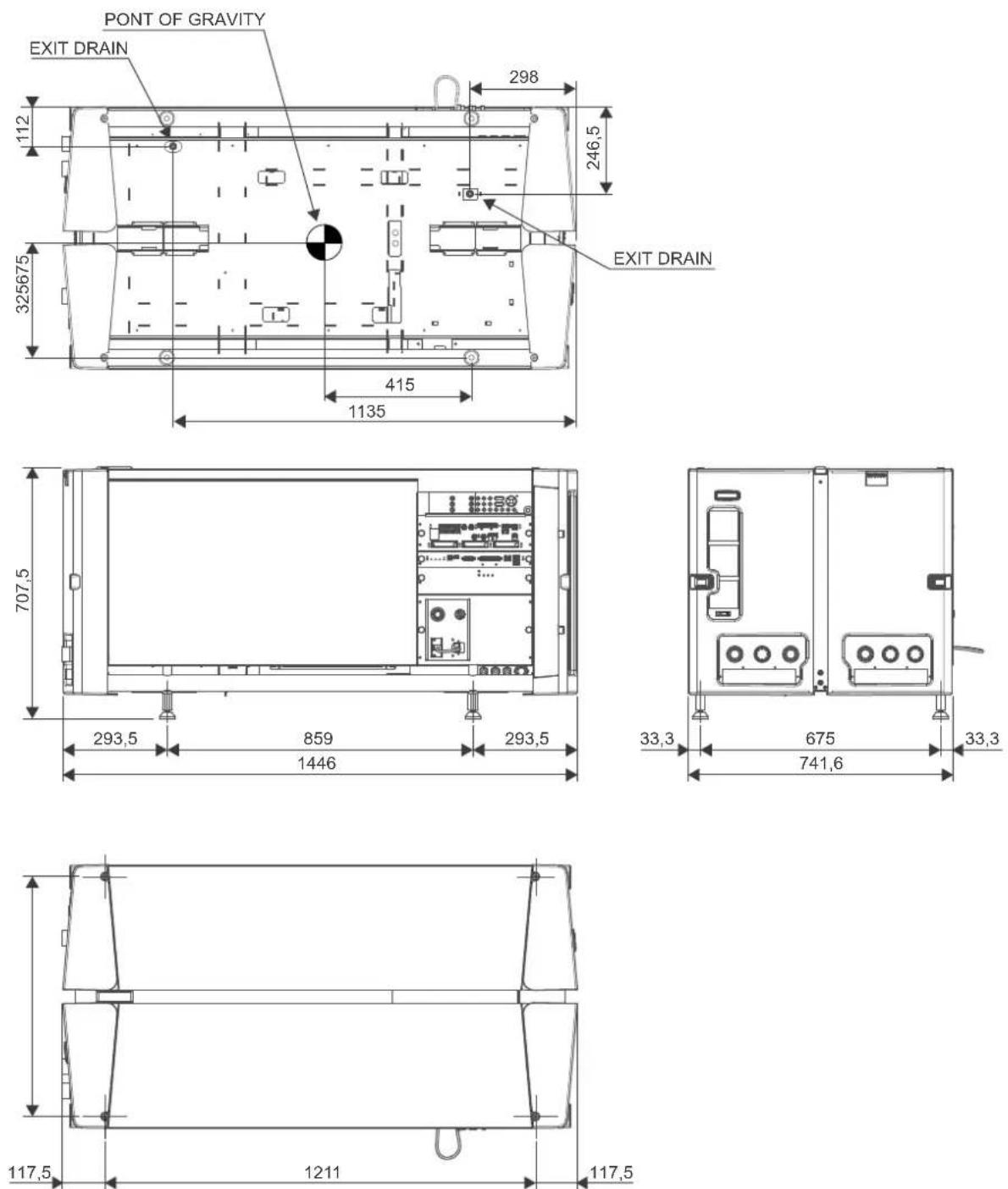
Image A-1: Dimensions given in millimeters.
A.6 Technical Regulations
Certificates

Image A-2: EAC mark

Image mark

A-3: CE

Image A-4: FCC label

Image A-5: RCM mark
Pin configurations
B
Overview
• About General Purpose Inputs & Outputs (GPIO)
• Pin configurations of the Cinema Controller communication ports
• Pin configurations of the ICMP(-X) communication ports
B.1 About General Purpose Inputs & Outputs (GPIO)

The Barco Cinema Controller and the Barco ICMP(-X) are equipped with GPIO ports. The electrical specifications described in this chapter are the same for both GPIO ports.
General Purpose inputs
The Barco Cinema Controller and the Barco ICMP (-X) have each eight (8) opto-isolated general purpose inputs available. These inputs are used to trigger the execution of macro files. For more explanation about the association of a macro to a GPI, consult the user guide of the Communicator.
Input voltage
The inputs can be directly driven from a TTL or CMOS output.
• The shape of the pulse must be rectangular.
- The duration of the pulse must be at least 50 milliseconds (shorter pulses are considered as a switch bounce)
• Minimum voltage : mV_n = 3,3 V
• Maximum voltage : V_max = 24 V
External power supply
When interfacing with contact closure outputs, an external power supply needs to be provided. Depending upon the configuration a suitable pull-up resistor needs to be added as well.
Input to projector Internal projector
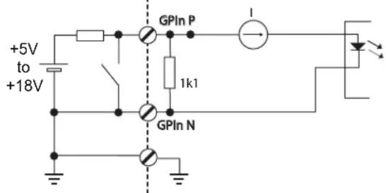
Image B-1
Input to projector Internal projector
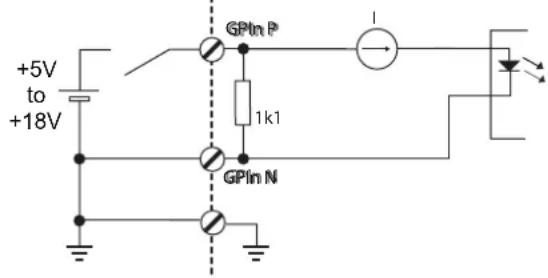
Cables
When long cable connections are required the use of shielded cables with twisted pairs is recommended. One twisted pair is to be assigned to each GP Input pair.
How to make the connection
When the power supply used to provide the DC voltage is isolated from ground (for example in the case of an AC adapter) it is recommended that the minus pole of that power supply is connected to ground (or to the projector chassis). This will avoid high common mode voltages at the projector GP Inputs. If that same power supply is used for other parts of the system, take care not to create ground loops. In any case when shielded cables are used that shield should be connected to the projector chassis.
General Purpose outputs
The Barco Cinema Controller and the Barco ICMP(-X) have each eight (8) opto-isolated outputs available. Four (4) of the outputs on the Cinema Controller are dedicated for TI. The other general purpose outputs can be controlled via software.
About an output
The output can generate a falling edge, rising edge, toggle or continuous toggle.
- Generate Falling Edge – generate a falling edge on the external GPO port if the present state of the output is high. If the present state of the external GPO is low, no edge will be generated.
- Generate Rising Edge – generate a rising edge on the external GPO port if the present state of the output is low. If the present state of the external GPO is high, no edge will be generated.
- Generate Toggle – generate a toggle on the external GPO port. If the present state of the output is low, a rising edge will be generated, followed by a falling edge. If the present state of the output is high, a falling edge will be generated, followed by a rising edge. Pulse width = 20 milliseconds.
- Generate Continuous Toggle - This command will generate a continuous toggle of the external GPO port. This toggle will continue until a Generate Falling Edge, Generate Rising Edge, or Generate Toggle command is received. The rate of toggle is 24Hz.
Output transistor
• Maximum output driving voltage max = 70 V
• Maximum current :max = 30 mA
• Maximum power dissipation : 120 mW
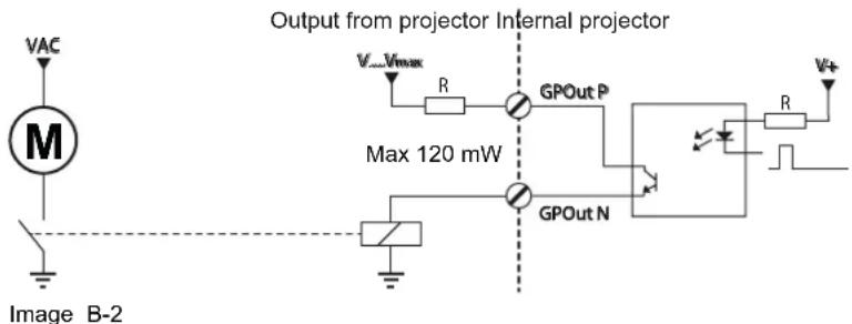

When the GPO driver inside the projector becomes powerless the GPO state changes to the default state. The default GPO state depends on the external system connected with the GPO port (pull-up or pull-down circuitry).
GPIO and projector Standby mode
Enter or leave the Standby mode can be done with GPIO of the Cinema Controller via two predefined Macros (not editable). Not with the GPIO of the ICMP(-X).
The GPO signals of the ICMP will return to their default output level when the projector is switched to Standby mode. This could generate unexpected "Falling Edge" triggers at the output pins. Also when awakening the projector (from Standby mode to Operational mode) the GPO signals of the ICMP may generate unexpected "Rising Edge" events.
GPO and projector switching On or Off
The GPO signals of the Cinema Controller and ICMP will return to their default output level when the projector is switched to power-off. This could generate unexpected "Falling Edge" triggers at the output pins. Also during power-on the GPO signals may generate unexpected "Rising Edge" events.
B.2 Pin configurations of the Cinema Controller communication ports
General purpose input/output (GPIO) of the Cinema Controller
| General Purpose In/Out | |||
| 1 3D Input | Reference P 20 3D Input Reference N | ||
| 2 3D Display Reference P | 21 3D | Display Reference N | |
| 3 GPIN 3 P (reserved) | 22 GPIN 3 N (reserved) | ||
| 4 GPIN 4 | P (reserved) 23 GPIN 4 N (reserved) | ||
| 5 GPIN 5 | P 24 GPIN 5 N | ||
| 6 GPIN 6 | P 25 GPIN 6 N | ||
| 7 GPIN 7 | P 26 GPIN 7 N | ||
| 8 GPIN 8 | P 27 GPIN 8 N | ||
| 9 3D Output Reference P 28 3D Output Reference N | |||
| 10 GPOUT | 2 P (reserved) 29 GPOUT 2 N (reserved) | ||
| 11 GPOUT | 3 P (reserved) 30 GPOUT 3 N (reserved) | ||
| 12 GPOUT | 4 P 31 GPOUT 4 N | ||
| 13 GPOUT | 5 P 32 GPOUT 5 N | ||
| 14 GPOUT | 6 P 33 GPOUT 6 N | ||
| 15 GPOUT | 7 P 34 GPOUT 7 N | ||
| 16 GPOUT | 8 P 35 GPOUT 8 N | ||
| 17 reserved | 36 reserved | ||
| 18 reserved | 37 reserved | ||
| 19 reserved | |||
Ethernet port
| 10/100 Base-T - RJ45 port 1000 | Base-T - RJ45 port | |||
| Pin | Pair | Color | Description | Description |
| 1 | 3 | white/green | TXD+ | TX0+ |
| 2 | 3 | green | TXD- | TX0- |
| 3 | 2 | white/orange | RXD+ | RX0+ |
| 4 | 1 | blue | - | TX1+ |
| 5 | 1 | white/blue | - | TX1- |
| 6 | 2 | orange | RXD- | RX0- |
| 7 | 4 | white/brown | - | Rx1+ |
| 8 | 4 | brown | - | RX1- |
3D interface
| Pin | Name | Pin | Name |
| 1 | +12V | 9 | +12V |
| 2 | Grnd | 10 | 3D Input Reference - |
| 3 | Grnd | 11 | 3D Display Reference + |
| 4 | RS232 RX | 12 | 3D Display Reference - |
| 5 | RS232 TX | 13 | CONN_3D MODE - |
| 6 | CONN_3D_MODE + | 14 | CONN_SYNC - |
| Pin Name Pin Name | ||
| 7 CONN_SYNC + 15 - | ||
| 8 3D Input Reference + |
B.3 Pin configurations of the ICMP(-X) communication ports
RJ-45 pin configuration
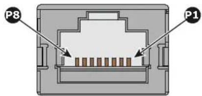
Image B-3
Audio Channels:
| AUDIO-AES 1-8 | ||
| Audio channel | AES pair RJ-45 pin | |
| 1, 2 1 + 1 | ||
| 1 - | 2 | |
| 3, 4 2 + 3 | ||
| 2 - | 6 | |
| 5, 6 3 + 4 | ||
| 3 - | 5 | |
| 7, 8 4 + 7 | ||
| 4 - | 8 | |
| AUDIO-AES 9-16 | ||
| Audio channel | AES pair RJ-45 pin | |
| 9, 10 | 5 + 1 | |
| 5 - | 2 | |
| 11, 12 | 6 + 3 | |
| 6 - | 6 | |
| 13, 14 | 7 + 4 | |
| 7 - | 5 | |
| 15, 16 | 8 + 7 | |
| 8 - | 8 | |
General Purpose Output:
| GPO 1-4 | |
| Definition | RJ-45 pin |
| EXT_GPOUT_1_P 1 | |
| EXT_GPOUT_1_N 2 | |
| EXT_GPOUT_2_P 3 | |
| EXT_GPOUT_2_N 4 | |
| EXT_GPOUT_3_P 5 | |
| EXT_GPOUT_3_N 6 | |
| EXT_GPOUT_4_P 7 | |
| EXT_GPOUT_4_N 8 | |
| GPO 5-8 | |
| Definition | RJ-45 pin |
| EXT_GPOUT_5_P 1 | |
| EXT_GPOUT_5_N 2 | |
| EXT_GPOUT_6_P 3 | |
| EXT_GPOUT_6_N 4 | |
| EXT_GPOUT_7_P 5 | |
| EXT_GPOUT_7_N 6 | |
| EXT_GPOUT_8_P 7 | |
| EXT_GPOUT_8_N 8 | |
General Purpose Input:
| GPI 1-4 | |
| Definition | RJ-45 pin |
| EXT_GPIN_1_P 1 | |
| EXT_GPIN_1_N 2 | |
| EXT_GPIN_2_P 3 | |
| EXT_GPIN_2_N 4 | |
| EXT_GPIN_3_P 5 | |
| EXT_GPIN_3_N 6 | |
| EXT_GPIN_4_P 7 | |
| EXT_GPIN_4_N 8 | |
| GPI 5-8 | |
| Definition | RJ-45 pin |
| EXT_GPIN_5_P 1 | |
| EXT_GPIN_5_N 2 | |
| EXT_GPIN_6_P 3 | |
| EXT_GPIN_6_N 4 | |
| EXT_GPIN_7_P 5 | |
| EXT_GPIN_7_N 6 | |
| EXT_GPIN_8_P 7 | |
| EXT_GPIN_8_N 8 | |
About 568A and 568B on an Ethernet connector RJ-45
TIA/EIA-568A and -568B are two standards for connecting Category 3 and Category 5 wire to connectors. Both are appropriate for high speed data, though 568B is somewhat more common for installed wiring and 568A is more common in jumpers. There is no performance advantage either way. The only real difference between the two is the order in which the pairs are used (orange and green).
Hold a cable as if to plug it into a wall jack, the locking tab down (contacts facing you). The contacts are numbered 1-8 from left to right. Here's what you will see:
| RJ-45 Pin Number(Left >Right copper side) | 568A 568B AES | -1-8 | |||
| 1 White/Green White/Orange | AES 1&2 +plus | ||||
| 2 Green Orange AES 1&2 | +minus | ||||
| 3 White/Orange | White/Green | AES 3&4 +plus | |||
| 4 Blue | Blue | AES 5&6 | +minus | ||
| 5 White/Blue | White/Blue | AES 5&6 +plus | |||
| 6 Orange | Green | AES 3&4 | +minus | ||
| 7 White/Brown | White/Brown | AES 7&8 +plus | |||
| 8 Brown | Brown | AES 7&8 | +minus | ||
568A and 568B may be used interchangeably in a system SO LONG AS both ends of a given cable are terminated the same way.
568A + 568B wiring is a crossover cable.
568A + 568A wiring is a straight cable.
568B + 568B wiring is a straight cable.
The mapping of the channels is done according to the Ethernet wiring scheme and gives us 100 Ohm per pai
Environmental information
C
Overview
- Disposal information
• China RoHS compliance
• Taiwan RoHS compliance
• Turkey RoHS compliance - Contact information
• Production address
• Download Product Manual
C.1 Disposal information
Disposal Information
Waste Electrical and Electronic Equipment

This symbol on the product indicates that, under the European Directive 2012/19/EU governing waste from electrical and electronic equipment, this product must not be disposed of with other municipal waste. Please dispose of your waste equipment by handing it over to a designated collection point for the recycling of waste electrical and electronic equipment. To prevent possible harm to the environment or human health from uncontrolled waste disposal, please separate these items from other types of waste and recycle them responsibly to promote the sustainable reuse of material resources.
For more information about recycling of this product, please contact your local city office or your municipal waste disposal service.
For details, please visit the Barco website at: http://www.barco.com/AboutBarco/weee
Disposal of batteries in the product

This product contains batteries covered by the Directive 2006/66/EC which must be collected and disposed of separately from municipal waste.
If the battery contains more than the specified values of lead (Pb), mercury (Hg) or cadmium (Cd), these chemical symbols will appear below the crossed-out wheeled bin symbol.
By participating in separate collection of batteries, you will help to ensure proper disposal and to prevent potential negative effects on the environment and human health.
C.2 China RoHS compliance
中国大陆 RoHS (Chinese Mainland RoHS)
According to the “Management Methods for the Restriction of the Use of Hazardous Substances in Electrical and Electronic Products” (Also called RoHS of Chinese Mainland), the table below lists the names and contents of toxic and/or hazardous substances that Barco’s product may contain. The RoHS of Chinese Mainland is included in the MCV standard of the Ministry of Information Industry of China, in the section “Limit Requirements of toxic substances in Electronic Information Products”.
| 零件项目(名称)Component Name | 有毒有害物质或元素Hazardous Substances or Elements | |||||
| 铅(Pb) | 汞(Hg) | 镉(Cd) | 六价铬(Cr6+) | 多溴联苯(PBB) | 多溴二苯醚(PBDE) | |
| 印制电路配件Printed Circuit Assemblies | X O X | O O | O | O | ||
| 外接电(线)缆External Cables | X O | O | O O | O | ||
| 内部线路Internal wiring | X O | O | O O | O | ||
| 镜头支架Lensholder | X O | O | O O | O | ||
| 光学镜头Optical lenses | X O O O O O | |||||
| 螺帽,螺钉(栓),螺旋(钉),垫圈,紧固件Nuts, bolts, screws, washers, Fasteners | X O O O O O | |||||
| 电源供应器Power Supply Unit | X O O O O O | |||||
| 风扇Fan | X O O O O O | |||||
| 本表格依据SJ/T 11364的规定编制This table is prepared in accordance with the provisions of SJ/T 11364.O:表示该有毒有害物质在该部件所有均质材料中的含量均在 GB/T 26572 标准规定的限量要求以下.O: Indicates that this toxic or hazardous substance contained in all of the homogeneous materials part is below the limit requirement in GB/T 26572.X:表示该有毒有害物质至少在该部件的某一均质材料中的含量超出 GB/T 26572 标准规定的限量要求.X: Indicates that this toxic or hazardous substance contained in at least one of the homogeneous used for this part is above the limit requirement in GB/T 26572. | ||||||

All Electronic Information Products (EIP) that are sold within Chinese Mainland must comply with the “Marking for the restriction of the use of hazardous substances in electrical and electronic product” of Chinese Mainland, marked with the Environmental Friendly Use Period (EFUP) logo. The number inside the EFUP logo that Barco uses (please refer to the photo) is based on the “General guidelines of environment-friendly use period of electronic information products” of Chinese Mainland.
C.3 Taiwan RoHS compliance
限用物質含有情況標示聲明書 (Declaration of the Presence Condition of the Restricted Substances Marking)
| 設備名稱:數字電影放映機(投影儀),型號(型式):DP4K-40LHC,DP4K-20LHCEquipment name: Digital Cinema Projector, Type designation: DP4K-40LHC,DP4K-20LHC | ||||||
| 限用物質及其化學符號Restricted substances and its chemical symbols | ||||||
| 單元Unit | 鉛Lead(Pb) | 汞Mercury(Hg) | 鎘Cadmium(Cd) | 六價鉻Hexavalentchromium(Cr6+) | 多溴聯苯Polybrominatedbiphenyls(PBB) | 多溴二苯醚Polybrominateddiphenylethers(PBDE) |
| 印製電路板配件Printed Circuit Assemblies | — | ○ — ○ | ○ ○ | |||
| 外接電(線)纜External Cables | — | ○ ○ ○ | ○ ○ | |||
| 內部線路Internal wiring | — | ○ ○ ○ | ○ ○ | |||
| 镜头支架Lensholder | — | ○ ○ ○ | ○ ○ | |||
| 光學鏡頭Optical lenses | — | ○ ○ ○ | ○ ○ | |||
| 螺帽,螺釘(栓),螺旋(釘),墊圈,緊固件Nuts,bolts,screws,washers,Fasteners | — | ○ ○ ○ | ○ ○ | |||
| 電源供應器Power Supply Unit | — | ○ ○ ○ | ○ ○ | |||
| 風扇Fan | — | ○ ○ | ○ ○ ○ | |||
| 備考1.“超出0.1 wt %”及“超出0.01 wt %”係指限用物質之百分比含量超出百分比含量基準值。Note 1:“Exceeding 0.1 wt %”and“exceeding 0.01 wt %”indicate that the percentage content of the restricted substance exceeds the reference percentage value of presence condition.備考2.“○”係指該項限用物質之百分比含量未超出百分比含量基準值。Note 2:“○”indicates that the percentage content of the restricted substance does not exceed the percentage of reference value of presence.備考3.“—”係指該項限用物質為排除項目。Note 3:The “—” indicates that the restricted substance corresponds to the exemption. | ||||||
C.4 Turkey RoHS compliance
Turkey RoHS compliance


[Republic of Turkey: In conformity with the WEEE Regulation]
C.5 Contact information
Barco contact information
Registered office address: President Kennedypark 35, 8500 Kortrijk, Belgium
Contact address: Beneluxpark 21, 8500 Kortrijk, Belgium
Importers contact information
To find your local importer, contact Barco directly or one of Barco's regional offices via the contact information given on Barco's web site, www.barco.com.
C.6 Production address
Factories
Barco NV (BELGIUM)
President Kennedypark 35, B-8500 Kortrijk
CFG Barco (Beijing) Electronics Co. Ltd.
中影巴可(北京)电子有限公司
3rd Floor, Barco Factory, No.16 Changsheng Road, Changping District, 102200, Beijing, P.R.C.
Barco Visual (Beijing) Electronics Co. Ltd.
巴可伟视(北京)电子有限公司
No.16 Changsheng Road, Changping District, 102200, Beijing, P.R.C
The made in country is indicated on the product ID label on the product itself.
Production date
The month and year of production is indicated on the product ID label on the product itself.
C.7 Download Product Manual
Download Product Manual
Product manuals and documentation are available online at www.barco.com/td.
Registration may be required; follow the instructions given on the website.
IMPORTANT! Read Installation Instructions before connecting equipment to the mains power supply.
Glossary
HD
Hazard Distance (HD) is the distance measured from the projection lens at which the intensity or the energy per surface unit becomes lower than the applicable exposure limit on the cornea or on the skin. The light beam is considered (to be) unsafe for exposure if the distance from a person to the light source is less than the HD
HD
Hazard Distance (HD) is the distance measured from the projection lens at which the intensity or the energy per surface unit becomes lower than the applicable exposure limit on the cornea or on the skin. The light beam is considered (to be) unsafe for exposure if the distance from a person to the light source is less than the HD
DMD
A digital micromirror device, or DMD, is an optical semiconductor that is the core of DLP projection technology.
Dew point
The dew point is the saturation temperature for water in air. The dew point is associated with relative humidity. A high relative humidity implies that the dew point is closer to the current air temperature. Relative humidity of 100% indicates the dew point is equal to the current temperature and that the air is maximally saturated with water. When the moisture content remains constant and temperature increases, relative humidity decreases.
RS232
An Electronic Industries Association (EIA) serial digital interface standard specifying the characteristics of the communication path between two devices using either D-SUB 9 pins or D-SUB 25 pins connectors. This standard is used for relatively short-range communications and does not specify balanced control lines. RS-232 is a serial control standard with a set number of conductors, data rate, word length and type of connector to be used. The standard specifies component connection standards with regard to computer interface. It is also called RS-232-C, which is the third version of the RS-232 standard, and is functionally identical to the CCITT V.24 standard. Logical '0' is > + 3V, Logical '1' is < - 3V. The range between -3V and +3V is the transition zone.
Trusted Device List (TDL)
The Goal of the TDL is to maintain timely and accurate information on participating auditoriums so that participating subscribers can obtain information needed to issue KDMs. The TDL has several data sources: Device manufacturers, Exhibitors, Deployment Entities, Integrators, Service Providers (interacting with Exhibitors), regional authorities and Support.
Public Key Infrastructure (PKI)
PKI is a framework for creating a secure method for exchanging information based on public key cryptography. The foundation of a PKI is the certificate authority (CA), which issues digital certificates that authenticate the identity of organizations and individuals over a public system such as the Internet. The certificates are also used to sign messages, which ensures that messages have not been tampered with.
\*.pem
Privacy-enhanced Electronic Mail. File format used to distribute digital signed certificates. Base64 encoded DER certificate, enclosed between "____BEGIN CERTIFICATE____" and "____END CERTIFICATE____"
Key Delivery Message (KDM)
The security key for each movie is delivered in a unique KDM for each digital cinema server. The security key is encrypted within the KDM, which means that the delivery of a KDM to the wrong server or wrong location will not work, and thus such errors cannot compromise the security of the movie. The KDM is a small file, and is typically emailed to the exhibitor. To create the correct set of KDMs for a site requires knowledge of the digital certificate in the projection system's media block.
Digital Cinema Package (DCP)
A Digital Cinema Package (DCP) is a collection of digital files used to store and convey Digital Cinema (DC) audio, image, and data streams. The term has been defined by Digital Cinema Initiatives (DCI). General practice adopts a file structure that is organized into a number of usually multi-gigabyte size Material eXchange Format (MXF) files, which are separately used to store audio and video streams, and auxiliary index files in XML format. The MXF files contain streams that are compressed, encoded, and encrypted, in order to reduce the huge amount of required storage and to protect from unauthorized use. The image part is JPEG 2000 compressed, whereas the audio part is linear PCM. The adopted (optional) encryption standard is AES 128 bit in CBC mode. The newer SMPTE standards are used to conform the recommendations among different tool vendors and producers. Interop, the legacy DCP standard, is still required to be supported by DCP players.
Digital Cinema Initiatives (DCI)
DCI is a joint venture of Disney, Fox, Paramount, Sony Pictures Entertainment, Universal and Warner Bros. Studios. DCI's primary purpose is to establish and document voluntary specifications for an open architecture for digital cinema that ensures a uniform and high level of technical performance, reliability and quality control. Note that the DCI specification is not a standard. Standards for digital cinema are the domain of the Society of Motion Picture and Television Engineers (SMPTE). "DCI compliant" is a term used to describe products that conform to the DCI specification. Products that have been tested per the DCI Compliance Test Plan (CTP) are posted at the DCI compliance web site. Notably, DCI compliance does not require compliance to the full set of SMPTE DCP standards. A copy of the most recent DCI specification can be downloaded from the DCI website (http://dcimovies.com).
USB
Universal Serial Bus (USB) is an industry standard developed in the mid-1990s that defines the cables, connectors and communications protocols used in a bus for connection, communication, and power supply between computers and electronic devices. USB 2.0 (also called "Hi-Speed"), adding higher maximum signaling rate of 480 Mbit/s (effective throughput up to 35 MB/s or 280 Mbit/s), in addition to the "USB 1.x Fu Speed" signaling rate of 12 Mbit/s.[16] USB 2.0 connectors are usually colored black. USB 3.0 defines a new SuperSpeed mode with a signaling speed of 5 Gbit/s and a usable data rate of up to 4 Gbit/s (500 MB/s). A USB 3.0 port is usually colored blue, and is backwards compatible with USB 2.0.
DisplayPort
Digital display interface developed by the Video Electronics Standards Association (VESA). This royalty-free interface is primarily used to connect a video source to a display device such as a computer monitor, though i can also be used to transmit audio, USB, and other forms of data. VESA designed it to replace VGA, DVI, ar FPD-Link. Backward compatibility to VGA and DVI by using active adapter dongles enables users to use DisplayPort fitted video sources without replacing existing display devices.
HDCP
High-bandwidth Digital Content Protection is a form of digital copy protection developed by Intel Corporation to prevent copying of digital audio and video content as it travels across DisplayPort, Digital Visual Interface (DVI), High-Definition Multimedia Interface (HDMI), Gigabit Video Interface (GVIF), or Unified Display Interface (UDI) connections, even if such copying would be permitted by fair use laws. The specification is proprietary, and implementing HDCP requires a license.
3G-SDI
Serial Digital Interface (SDI) is a serial link standardized by ITU-R BT.656 and the Society of Motion Picture and Television Engineers (SMPTE). SDI transmits uncompressed digital video over 75-ohm coaxial cable within studios, and is seen on most professional video infrastructure equipment. The first revision of the standard, SMPTE 259M, was defined to carry digital representation of analog video such as NTSC and PAL
over a serial interface and is more popularly known as standard-definition (SD) SDI. The data rate required to transmit SD SDI is 270 Mbps. With the advent of high-definition (HD) video standards such as 1080i and 720p the interface was scaled to handle higher data rates of 1.485 Gbps. The 1.485-Gbps serial interface is commonly called the HD SDI interface and is defined by SMPTE 292M, using the same 75-ohm coaxial cable. Studios and other video production facilities have invested heavily on the hardware infrastructure for coaxial cable and have a vested interest in extending the life of their infrastructure. Fortunately, SMPTE recently ratified a new standard called SMPTE 424M that doubles the SDI data rates to 2.97 Gbps using the same 75-ohm coaxial cable. This new standard, also called 3-Gbps (3G)-SDI, enables higher resolution of picture quality required for 1080p and digital cinema.
HDMI
HDMI (High-Definition Multimedia Interface) is a compact audio/video interface for transferring uncompressed video data and compressed/uncompressed digital audio data from a HDMI-compliant device ("the source device") to a compatible computer monitor, video projector, digital television, or digital audio device. HDMI is a digital replacement for existing analog video standards.
HDMI
HDMI (High-Definition Multimedia Interface) is a compact audio/video interface for transferring uncompressed video data and compressed/uncompressed digital audio data from a HDMI-compliant device ("the source device") to a compatible computer monitor, video projector, digital television, or digital audio device. HDMI is a digital replacement for existing analog video standards.
Scheimpflug principle
The "plane of sharp focus" can be changed so that any plane can be brought into sharp focus. When the DM plane and lens plane are parallel, the plane of sharp focus will also be parallel to these two planes. If, however, the lens plane is tilted with respect to the DMD plane, the plane of sharp focus will also be tilted according to geometrical and optical properties. The DMD plane, the principal lens plane and the sharp focus plane will intersect in a line below the projector for downward lens tilt.
Scheimpflug principle
The "plane of sharp focus" can be changed so that any plane can be brought into sharp focus. When the DM plane and lens plane are parallel, the plane of sharp focus will also be parallel to these two planes. If, however, the lens plane is tilted with respect to the DMD plane, the plane of sharp focus will also be tilted according to geometrical and optical properties. The DMD plane, the principal lens plane and the sharp focus plane will intersect in a line below the projector for downward lens tilt.
Screen Brightness
Screen Brightness, or how bright a screen will look, involves measuring the light reflected from its surface to our eyes. It takes into account the luminous flux (lumens) falling over its entire area (lux) and how reflective the surface of the screen is. It literally is a measure of the light bouncing off the screen. Luminance is measured in foot-lamberts. One foot-Lambert of luminance is equal to one lumen per square foot.
Index
Numbers/Symbols
3G-SDI 95
A
About this manual 10
Access
Mains compartment 51
Address 179
Adjust
Convergence
Green 132
Red 131
Air flow
Projector 28
AUDIO-AES 93
Authorization
Security warning
Clear 151
Awake 71
B
Back Focal Length 115
Adjustment 121
Backlight
Color 67
Batteries
Disposal 176
C
Calibration 135
Color 139
Luminance 141
Process 136
White point 137
CertID 89
Check
Dust filter 148
Chiller
Communication port 51
Chillers and hoses 28
Cinema Controller 74
Cleaning
Exterior 151
Filters 149
Filters (wet) 149
Lens 150
Color
Backlight 67
Calibration 139
Commander 34
Communication 69
AUDIO-AES 93
GPI 94
GPO 93
Introduction 70
LAN 94
SYNC 94
USB 2.0 94
USB 3.0 94
USB port 74
Communication port
Chiller 51
Projector 51
Communication ports 74, 93
Communicator 33
Touch Panel 58
Component
Location 28
Configuration 92
Connect
Communication port 51
Mains 55
Safety interlocks 53
Convention
Orientation 27
Convergence 127
Control knobs 128
Controls
Extenders 128
Green onto blue 132
Prepare 130
Red onto blue 131
Test pattern 129
Cooling liquid
Safety precautions 17
Cover
Mains compartment 51
Side 155
Top 154
Covers
Install 153
Remove 153
D
Delta (Δ) configuration 54
Device certificate
Download 91
ICMP 91
ICMP(-X) 89
Dimensions
Thor series projector 165
DisplayPort 95
Specifications 97
Disposal 176
Disposal of batteries 176
DMD cooling 29
Download
Device certificate 91
Product manual 179
Drying
Filters 149
Dust filter
Large
Replace 148
E
Enclosed projection 22
Environmental information 175
Disposal 176
RoHS compliance 176
Taiwan 178
Turkey 178
Expected
From you 10
Exterior
Cleaning 151
External safety interlocks 30
F
Filters
Cleaning 149
Cleaning (wet) 149
Fixate
Lens Holder front plate 120
Focus 66
G
General considerations 12
General Purpose I/O 168
Getting started 35
GPI 94
GPIO 168
GPO 93
H
Hazard Distance 20, 22
Modifying optics 24
Hazardous Chemicals 17–18
HDD 81
About 81
Degrade mode 81
RAID broken 82
RAID recovery 82
Remove 84, 86
Status LEDs 87
Storage 82
Storage capacity 82
Troubleshooting 87
Validated list 83
HDMI 95
HDMI 1.4
Specifications 104
HDMI 2.0 95
Specifications 101
High Brightness precautions 20
Hoses 29
Install 49
|
ICMP(-X) 77
ICMP(-X) introduction 79
ICMP(-X) reset 107
Important safety instructions 13
Importer 179
Initial inspection 40
Input 69
Introduction 70
Input & communication
Communication ports 74
Input & Communication
Local Keypad 72
Install
Covers 153
Hoses 49
Lens 63
Power loop through 56
Safety interlocks 53
Touch Panel 58
UPS connection 57
Installation
Overview 42
Power input configuration 54
Installation process 41
Installation requirements 36
Internal clock 92
Introduction
Communication 70
Input 70
K
KDM
ICMP(-X) 89
Keypad
Backlight
Color 67
L
LAN 94
Large dust filter
Replace 148
Laser status 71–72
Lens
Cleaning 150
Focus 66
Installation 63
Removal 65
Scheimpflug 116–117
Shift 66
Zoom 66
Lens Holder
Front plate 120
Lenses 61
lens selection 62
Lenses
Available 62
Lens Holder 61
Local Keypad 72
Location
Component 28
Luminance
Calibration 141
M
Mains
Connect 55
Mains compartment
Access 51
Cover 51
Maintenance 147
3 month 144
Maintenance program 143
1 Month 144
Manual
Use 10
Mechanical check 40
N
network streaming (Live IP)
Specifications 96
Network Time Protocol 92
Notice on optical radiation
Optical radiation 12
Notice on safety 12
0
Obtain
Device certificate 91
ON/OFF 112
Open
Cover door 154
Orientation
Convention 27
Owner's record 12
P
Physical installation 45–46
Pin configuration
Communication ports 169
Pin configurations 167
ICMP(-X) 171
Power input setup 54
Power loop through
Installation 56
Product safety labels 18
Production 179
Projection screen 38
Projector
Air flow 28
Communication port 51
Projector ON/OFF explained 112
Projector status 70
R
Rear projection 22
Remove
Covers 153
HDD 84, 86
Lens 65
Protection bars 46
Side cover 155
Top cover 154
Replace
Dust filter
Large 148
Requirements
Condensed water 37
Cooling 36
Power 37
Projection screen 38
Projector weight 38
UPS 38
Reset button 107
RS232 76
S
Safety 11
Battery explosion 15
Electrical shock 13
Fire hazard 14
Hazard Distance 20, 22
Hazardous Chemicals 17–18
Personal injury 15
Projector damage 16
Safety Data Sheet (SDS) 17–18
Servicing 16
Safety Data Sheet (SDS) 17–18
Safety interlocks
Connect 53
Safety precautions
Cooling liquid 17
Safety system 30
Safety training 12
Scheimpflug 115–117
Adjustment points 116
Scheimpflug's law 116
SDI
Specifications 98
Serial communication 76
Shift 66
Side cover
Remove 155
Source input
3G-SDI 95
DisplayPort 95
HDMI 95
HDMI 2.0 95
Source input ports 94
Specification
ICMP 163
ICMP-X 164
Specifications 157
DisplayPort 97
HDMI 1.4 104
HDMI 2.0 101
network streaming (Live IP) 96
SDI 98
Thor 158
Thor+ 160
Stacking 38
Standby mode 71
Star (Y) configuration 54
Starting up 109
Switching on 110
Status LEDs 88
HDD 87
Status light 70, 72
Status light lasers 71
Switching OFF 111
Switching on 110
SYNC 94
System overview 25
Chillers and hoses 28
Commander 34
Communicator software 33
Thor 27
T
Tail light 70
TDL
ICMP(-X) 89
Technical Regulations 166
Test Pattern
Convergence 129
This manual 9
Thor 27
Three phase
Configuration 54
Top cover
Remove 154
Touch Panel
Install 58
Introduction 31
U
Unpacking 39
UPS 38
UPS connection
Installation 57
USB 2.0 94
USB 3.0 94
USB port 74
User definition 13
V
Vacuum
Filters 149
W
Washing
Filters 149
Welcome 9
What are the possible HDD swaps 83
White point
Calibration 137
Z
Zoom 66

- Changes
- Copyright ©
- BSMI Reporting Obligor Information / 報驗義務人資訊
- Federal Communications Commission (FCC Statement)
- EN55022/CISPR22 Class A ITE (Information Technology Equipment)
- Product Security Incident Response
- Patent protection
- Guarantee and Compensation
- Software License Agreement
- Terms and Conditions:
- Disclaimer of Warranty:
- GNU-GPL code
- Trademarks
- Table of contents
- Welcome....9
- Safety Information 11
- System overview 25
- Getting started 35
- Installation process 41
- Physical installation....45
- Lenses & Lens selection....61
- Input & Communication....69
- ICMP(-X) 77
- Starting up 109
- Scheimpflug ....115
- Convergence 127
- Calibration 135
- Preventative maintenance actions.... 143
- Maintenance procedures 147
- Removal and installation of the projector covers.... 153
- A Specifications....157
- B Pin configurations 167
- C Environmental information 175
- Glossary 181
- Index 185
- Welcome 1
- Congratulations
- Overview
- About this manual
- How to use this manual?
- What's expected from you?
- Safety Information 2
- About this chapter
- Clarification of the term "Thor series" used in this document
- Model certification name
- General considerations
- General safety instructions
- Notice on safety
- Notice on optical radiation
- Owner's record
- Safety training to be provided by the installer
- Users definition
- Restricted access location
- Exclusion zone
- Restriction zone
- Important safety instructions
- To prevent the risk of electrical shock
- To prevent fire hazard
- To prevent battery explosion
- To prevent personal injury
- On servicing
- To prevent projector damage
- Safety Data Sheets for Hazardous Chemicals
- Safety precautions Hazardous Chemicals
- Cooling liquid: Blue antifreeze
- Cleansing agent: sodium carbonate crystals _2 C(OI _3 )
- Product safety labels
- Light beam related safety labels
- High Brightness precautions: Hazard Distance (HD)
- Restriction Zone (RZ) based on the HD
- USA market (For FDA notice No 57)
- HD for fully enclosed projection systems
- HD in function of modifying optics
- System overview
- 3
- Thor
- Introduction
- Convention projector orientation
- Component location
- Air flow
- Chillers and hoses
- DMD
- Chiller cooling circuit expansion for DMD cooling
- Hoses
- Safety system
- Safety controller
- Beam enable key
- External beam enable key
- Beam stop button
- External safety interlocks
- Communicator Touch Panel
- Communicator Touch Panel for digital cinema projectors
- Flexible Touch Panel interface
- Parts location of the Touch Panel interface
- Touch Panel power/data customized cable
- Communicator PC version
- Configuration tool
- Quick and Easy configuration
- Commander & Web Commander
- Commander
- Web Commander
- Getting started 4
- Installation requirements
- Environment conditions
- Measures to resolve radio interference
- Cooling requirements
- Dew point
- Condensed water drain requirements
- Main Power requirements
- • Electrical ratings for Star system (3W+N+PE):
- UPS requirements
- Projection screen
- Projector weight
- Unpacking the projector
- What you need to do?
- Required tools
- How to unpack the projector?
- Initial inspection
- General
- Box content
- Mechanical check
- Installation process
- 5
- Installation process overview
- Installation process from A to Z
- Physical installation
- 6
- Removing the transport protection bars
- What needs to be done?
- How to remove the transport protection bars?
- Positioning the projector at port window
- General guidelines
- Projector centering
- Projector tilting
- Connecting the hoses with projector and chillers
- What has to be done?
- Hoses IN/OUT connection scheme
- How to connect the hoses?
- Connecting the data cable with projector and chillers
- Required parts
- Accessing the mains compartment
- How to access the mains compartment?
- Connecting the external safety interlocks
- How to connect the external safety interlocks with the projector?
- Three phase power input configuration of the projector
- About the power input
- How to switch from a Y-connection to -connection
- How to switch from a -connection to Y-connection
- Connecting the projector with the mains electricity
- How to connect the projector with the mains electricity?
- Power loop through to the projector electronic
- How to loop through the power?
- Connecting a UPS to the projector electronics
- How to connect the UPS
- Installing the Communicator Touch Panel
- How to install the Touch Panel interface onto the top of the projector?
- Lenses & Lens selection
- 7
- Available lenses
- Lens selection
- Barco.com | Cinema Calculator
- Lens installation
- How to install a lens into the Lens Holder?
- Lens removal
- Lens shift, zoom & focus
- Motorized lens adjustment
- Maximum shift range
- How to shift the lens of the Thor series?
- How to zoom in or out?
- How to focus?
- Button backlight colors
- Input & Communication
- 8
- Introduction
- Projector Status
- About the projector Status Light
- Status overview
- Yellow
- Red
- Operational mode
- Standby mode
- Laser Status
- About the Laser Status Light
- Local Keypad
- Functionality of the buttons
- Numeric buttons (No.1 - 6)
- Marker area
- Standby button
- Star button
- Light button
- Focus button
- Shift button
- Dowser button
- Test Pattern button
- Key button
- Zoom button
- Media control buttons
- Cinema Controller
- Functionality
- Diagnostic LEDs
- USB IN port
- USB OUT port
- 3D INTERFACE
- GENERAL PURPOSE INPUT/OUTPUT (GPIO)
- Wide Area Network (WAN)
- Local Area Network (LAN: 10/100/1000 base-T)
- Cinema Controller functions:
- Virtual comport (RS232 serial communication)
- RS232
- ICMP(-X)
- 9
- ICMP(-X) introduction
- About ICMP
- Front face of the ICMP-X
- Front face of the ICMP with HDMI 2.0
- Front face of the ICMP with DisplayPort and HDMI 1.4
- GEN1 and GEN2 storage controller
- How to recognize an ICMP-X or an upgraded ICMP with GEN2 storage controller
- ICMP(-X) HDD
- About ICMP(-X) HDD
- About degraded mode
- About "RAID recovery" process
- About RAID broken
- Exchange or re-use of a disk set
- HDD storage capacity
- HDD storage
- HDD models validated by Barco
- What are the possible HDD swaps
- List of available actions
- Installing a HDD into the ICMP(-X)
- Re-initialization or rebuild of RAID
- How to install a HDD?
- Removing a HDD from the ICMP(-X)
- How to remove a HDD?
- HDD status LEDs
- Status LEDs on ICMP(-X)
- Troubleshooting
- Situation
- Solution
- ICMP(-X) status LEDs
- ICMP(-X) device certificate
- Purpose of the Barco ICMP(-X) device certificate
- Trusted Device List (TDL)
- Public Key Infrastructure (PKI)
- \*.pem
- Key Delivery Message (KDM)
- Digital Cinema Package (DCP)
- Digital Cinema Initiatives (DCI)
- Obtaining the Barco ICMP(-X) certificate
- Using the CertID label to download the ICMP(-X) certificate
- Using control software to obtain the ICMP(-X) certificate
- ICMP(-X) configuration via Communicator
- About ICMP(-X) configuration
- About Default settings
- About the ICMP(-X) internal clock
- About test patterns
- ICMP(-X) communication ports
- AUDIO-AES 1-8 (9-16)
- GPO 1-4 (5-8)
- GPI 1-4 (5-8)
- SYNC IN / OUT
- LAN 1 (2)
- USB 2.0
- USB 3.0
- USB
- ICMP(-X) source input ports
- ICMP(-X) network streaming (Live IP) specifications
- About network streaming
- Minimum requirements
- Network Streaming
- Stream containers
- Video formats
- Audio formats
- Subtitle formats
- ICMP DisplayPort specifications
- DisplayPort
- HDCP
- DisplayPort specifications
- Notes:
- ICMP(-X) SDI specifications
- 3G-SDI
- SDI terminology
- Dual-Link HD-SDI signal
- 3G HD-SDI signal
- Dual Stream 3G HD-SDI signal
- SMPTE 292M STANDARD 1.485 Gb/s HD-SDI SIGNALS
- SMPTE 424M 3G HD-SDI 2.970 Gb/s SIGNALS
- ICMP(-X) HDMI 2.0 specifications
- HDMI
- HDMI 2.0 specifications
- HDR (SMPTE ST 2084)
- HDMI 2.0 Cable requirements
- ICMP HDMI 1.4 specifications
- HDMI 1.4 specifications
- ICMP(-X) reset
- ICMP(-X) reset possibilities
- How to reset the ICMP(-X)?
- Starting up 10
- Switching the Thor series projector ON
- About the start up process
- Start up checklist
- Start up procedure
- Switching the Thor series projector OFF
- About the switch off process
- How to switch the Thor series OFF?
- Projector ON/OFF cycle explained
- Stage description:
- Scheimpflug
- 11
- Scheimpflug principle
- Scheimpflug introduction
- What is Scheimpflug?
- Scheimpflug adjustment points
- Scheimpflug adjustment
- Preparation steps:
- Scheimpflug adjustment steps:
- Fixation of the Lens Holder front plate
- When fixing the Lens Holder front plate
- How to fix the Lens Holder front plate?
- Back Focal Length adjustment
- When to adjust the Back Focal Length?
- What is Back Focal Length adjustment?
- How to check the Back Focal Length?
- How to adjust the Back Focal Length?
- Convergence
- 12
- Convergence controls
- Extended control knobs
- Convergence test pattern
- Adjustment Range
- Troubleshooting 'dead zone' of control knob
- Preparing for convergence adjustment
- Converging the red pattern onto the blue pattern
- Converging the RED pattern onto the BLUE pattern
- Converging the green pattern onto the blue pattern
- Converging the GREEN pattern onto the BLUE pattern
- Calibration 13
- Calibration process
- Calibration process overview
- - External 3D
- Verify corrected colors.
- Luminance calibration.
- White point calibration
- Laser RGB correction
- 2D and 3D projector mode
- Luminance balancing
- White point calibration procedure:
- Color gamut calibration
- Color Gamut
- Why apply color correction?
- Electronic correction
- Influence of aspect ratio
- 3D color calibration
- Color gamut calibration procedure:
- Luminance calibration
- Screen Brightness
- Why calibrating the Light Sensor?
- Light Sensor Calibration process
- Preventative maintenance actions
- 14
- Maintenance program
- 1 month maintenance actions
- MAINTENANCE TYPE A (perform every month)
- 3 month maintenance actions
- MAINTENANCE TYPE B (perform every three months)
- Maintenance procedures
- 15
- Check the dust filters
- How to check the large dust filter?
- Vacuum cleaning of the dust filters
- When to vacuum clean the dust filters?
- How to vacuum-clean the dust filter?
- Washing and drying the dust filters
- About filter washing and drying
- Cleansing agent
- How to wash and dry the dust filters?
- Cleaning the lens
- How to clean the lens?
- Cleaning the exterior of the projector
- Authorization to clear security warning on the projector
- Authorization procedure to clear security warning
- Removal and installation of the projector covers
- 16
- Opening the front and rear cover doors
- Open cover doors
- Removal of the top cover
- How to remove a top cover?
- Removal of the side covers
- How to remove a side cover?
- Specifications
- A
- A.1 Specifications of the Thor
- A.2 Specifications of the Thor+
- A.3 Specifications of the ICMP
- A.4 Specifications of the ICMP-X
- A.5 Dimensions of the Thor series projector
- A.6 Technical Regulations
- Pin configurations
- B
- B.1 About General Purpose Inputs & Outputs (GPIO)
- General Purpose inputs
- Input voltage
- External power supply
- Cables
- How to make the connection
- General Purpose outputs
- About an output
- Output transistor
- GPIO and projector Standby mode
- GPO and projector switching On or Off
- B.2 Pin configurations of the Cinema Controller communication ports
- B.3 Pin configurations of the ICMP(-X) communication ports
- About 568A and 568B on an Ethernet connector RJ-45
- Environmental information
- C
- C.1 Disposal information
- Disposal Information
- Disposal of batteries in the product
- C.2 China RoHS compliance
- 中国大陆 RoHS (Chinese Mainland RoHS)
- C.3 Taiwan RoHS compliance
- C.4 Turkey RoHS compliance
- C.5 Contact information
- Barco contact information
- Importers contact information
- C.6 Production address
- Factories
- Production date
- C.7 Download Product Manual
- Download Product Manual
- Glossary
- HD
- Index
- Numbers/Symbols
- D
- E
- F
- G
- H
- |
- K
- L
- M
- N
- 0
- P
- R
- S
- T
- U
- V
- W
- Z
Brand : Barco
Model : Thor+
Category : Projector