
CTHD-61B - Vidéo-projecteur Barco - Free user manual and instructions
Find the device manual for free CTHD-61B Barco in PDF.


| Product Type | Video projector |
| Brand | Barco |
| Model | CTHD-61B |
| Display Technology | DLP |
| Resolution | 1920 x 1080 (Full HD) |
| Brightness | 6000 ANSI lumens |
| Contrast Ratio | 2000:1 |
| Lamp Type | UHP |
| Lamp Life | 2000 hours (typical) |
| Power Consumption | 500 W (typical) |
| Weight | 15 kg (33 lbs) |
| Dimensions (W x D x H) | 500 x 400 x 200 mm |
| Inputs | HDMI, DVI, VGA, Composite, S-Video |
| Outputs | Monitor out (VGA), RS-232 control |
| Lens Shift | Vertical and horizontal shift |
| Keystone Correction | Vertical and horizontal |
| Noise Level | 35 dB (typical) |
| Operating Temperature | 0°C to 40°C |
| Safety | Class 1 laser product, CE, FCC compliant |
| Maintenance | Clean air filter every 500 hours; replace lamp as needed |
| Repairability | Serviceable by qualified technicians; spare parts available |
Frequently Asked Questions - CTHD-61B Barco
User questions about CTHD-61B Barco
0 question about this device. Answer the ones you know or ask your own.
Ask a new question about this device
Download the instructions for your Vidéo-projecteur in PDF format for free! Find your manual CTHD-61B - Barco and take your electronic device back in hand. On this page are published all the documents necessary for the use of your device. CTHD-61B by Barco.
USER MANUAL CTHD-61B Barco
an introduction to the projector
CT series
User Manual
natural_image
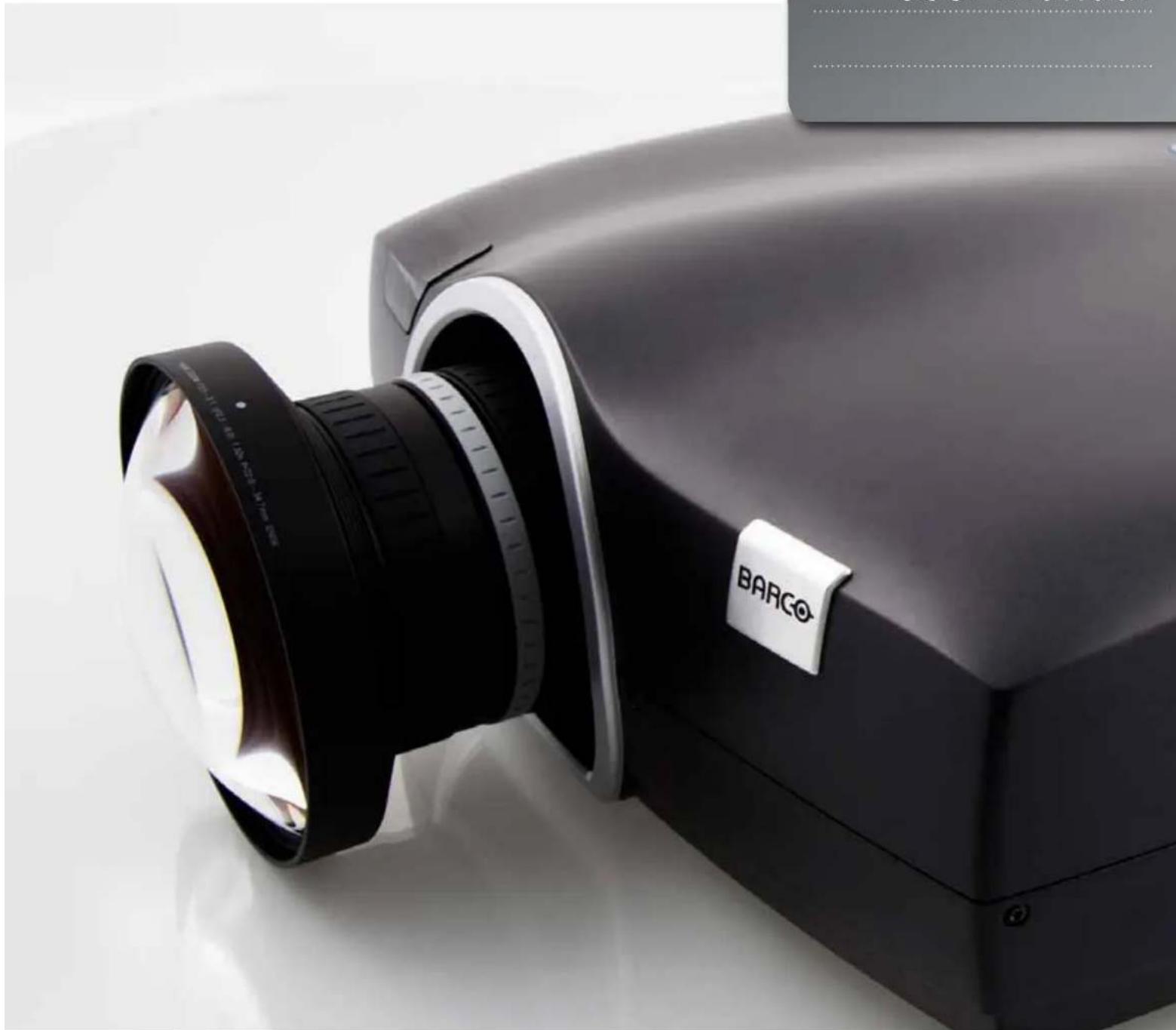
Close-up of a black BARCO camera lens assembly with a white tag, no visible text or symbols on the device itself.Contents
1 Introduction 7
1.1 Thank you
1.2 Training
1.3 Symbols used in this documentation
2 Safety and compliance 9
2.1 General safety considerations
2.2 Information/Warning - Potential Mercury Vapour Health Issues
2.3 FCC compliance
2.4 Disposal information
2.4.1 Statement WEEE (Waste Electrical and Electronic Equipment)
2.4.2 Disposal of batteries in the product
2.4.3 Turkey RoHS compliance
2.5 Service
3 What is in the box? 13
4 Installation 15
4.1 System considerations
4.2 Ventilation
4.2.1 Ventilation accessories
4.3 Ceiling and rig mounting
4.4 Locking the projector
4.5 Projector angle (tilt)
4.6 Selecting a lens
4.6.1 Inserting a lens
4.6.2 Changing/removing a lens
4.6.3 Lens range
4.7 Lens lock
4.8 Lens shift
4.10 Zoom, focus and iris
4.11 Making the connections
4.12 Connecting video and data sources
4.13 Connecting control interfaces
4.14 Source format integrity - EDID
4.15 Image sizes
4.9 Lens planarity (Scheimpflug adjustment)
5 Overview 25
5.1 Keypad and indicator
5.2 Wireless remote control
5.3 Connectors
5.3.1 Signal connectors
5.3.2 Control connectors
5.4 Menu system
5.4.1 Top menu
5.5 3D main menu
5.5.1 3D > Dual head setup sub menu
5.6 Picture main menu
5.6.1 Picture > RealColor sub menu
5.6.2 Picture > Advanced sub menu
5.7 Installation main menu
5.7.1 Installation > EDID sub menu
5.7.2 Installation > Synchronization sub menu
5.8 Settings main menu
5.8.1 Settings > Pin Code sub menu
5.8.2 Settings > Network sub menu
5.8.3 Settings > Factory Reset sub menu
5.8.4 Settings > Service sub menu
5.9 Languages main menu
5.10 Status main menu
5.10.1 Status > Source Information sub menu
5.10.2 Status > Source Information > Advanced sub menu
5.10.3 Status > Source Synchronisation sub menu
6 Functionality 49
6.1 Powering On and Off
6.1.1 Manual power control
6.1.2 DPMS - power down
6.2 Image alignment
6.2.1 Image orientation
6.3 Language
6.4 System status
6.5 Lamp power
6.6 Source selection, source scan
6.7 On screen display (OSD) messages
6.7.1 Disabling the STATUS indicator
6.7.2 Setting the background color
6.7.3 Setting OSD menu timeout
6.7.4 Selecting the startup logo
6.8 Picture by Picture (PbP)
6.9 Standby ECO mode
6.10 PIN code
6.11 Disabling the wireless remote control (IR) receivers
6.12 Software upgrades
7 Optimising the image 55
7.1 Calibration data
7.1.1 Updating RealColor™ calibration data
7.1.2 RealColor™ modes
7.2 Setting a white point or color temperature
7.2.1 Defining the system color gamut
7.3 Gamma
8 Technical specifications 63
9 Lamp change 65
1 Introduction
1.1 Thank you
Thank you for purchasing this projector.
When referring to the term CT series in this document the content is applicable for the following Barco products:
• CTHD-61B (1920x1080)
• CTWU-61B (1920×1200)
• CTWQ-51B (2560×1600)
- CTPN-41B (2560x1080)
The CT series projectors set an industry benchmark for projectors in its size and performance category. If realism and reliability are key criteria this high resolution DLP-technology projector with high performance optics and lenses, updated signal processing and built-in frame-lock synchronisation, makes it the ideal projector for multi-channel visualization and simulation applications. In addition to the excellent image performance it is capable of showing Active Stereo 3D.
1.2 Training
To get the best performance out of the projector as well as the system, training at Barco is highly advised, in addition to studying this user guide. Various courses are available. At the University, skilled trainers will teach you basic projector use as well as more advanced set-up and configuration across multiple application areas. Go to www.barco.com for easy access to more information.
1.3 Symbols used in this documentation

WARNING: Used to point out potential danger to people or equipment when using the product in certain ways.

NOTE: Used to point out essential handling requirements for the projector. If not acted on, they may cause product malfunctioning.

TIP: Presenting advice which benefits the projector usage or conditions related to projector performance.
The specifications and functionality of this projector may change without prior notice. Pictures/drawings or features in this user guide may be different from your projector depending on model/version.
2 Safety and compliance
2.1 General safety considerations
- Use only the cables and cords supplied with the projector or original replacement cables. Using other cables or cords may lead to malfunction and permanent damage to the unit.
- Always use 3-prong (grounded) power cord to ensure proper grounding of the unit. Never use 2-prong power cords, as this is dangerous and could lead to electrical shock. For the grounding of the coax connection, equal ground potential must be ensured. To be installed by trained personnel.
- Never open the unit. The projector contains no user serviceable parts. Refer all repairs to qualified personnel only. Make sure that no objects enter into the vents and openings of the set.
- Do not spill any liquids on the projector or into the vents or openings of the unit.
- Always remove lens cap before switching on the projector. If the lens cap is not removed, it may melt due to the high energy light emitted through the lens. Melting the lens cap may permanently damage the surface of the projection lens.
- Do not look into the projection lens when the projector is switched on. The strong light may permanently damage sight.
- Only place the projector on a stable surface, or mount it securely using an approved ceiling-mount.
- Do not drop the projector.
- Always operate the projector according to the rotation guidelines. Operating the unit in other positions may reduce lamp life significantly, and may lead to overheating, resulting in malfunctioning.
- Always allow ample airflow through the projector. Never block any of the air vents. Never cover the unit in any way while running. Allow for sufficient distance to walls and ceilings to avoid overheating.
- Minimum safety distance to any side of the unit is 50cm / 20" in any direction (15 cm/ 6" to ceiling).
- Hot air is exhausted from the rear vent. Do not place objects that are sensitive to heat nearer than 50cm / 20" to the exhaust vent.
- The projector is designed for indoor use only. Never operate the unit outdoors.
- Do not operate the projector outside its temperature and humidity specifications, as this may result in overheating and malfunctioning.
- Only connect the projector to signal sources and voltages as described in the technical specification. Connecting to unspecified signal sources or voltages may lead to malfunction and permanent damage of the unit.
- In order to prevent damage to the projector caused by over-voltages (e.g. lightning), we recommend connection to a line (mains) circuit which has over voltage protection.
- Allow lamp to cool down for at least 60 minutes before changing. USE ONLY ORIGINAL LAMPS.
- Connecting sources to a powered projector may result in product failure. It is recommended that the power cable connector (projector-end) or the mains power socket is accessible whilst the product is in use to enable mains power to be disconnected or switched off when connecting source devices. This should be considered during product installation.
2.2 Information/Warning - Potential Mercury Vapour Health Issues
This projector uses a very powerful UHP™ lamp for illumination to produce an extremely bright image.
This technology is similar to other high-pressure discharge lamps that are extensively used in cars, street lights and other lighting appliances today. These lamps, like fluorescent lighting, contain small amounts of mercury. The amount of mercury present in a lamp is far below the limits of danger set by the authorities. It is however very important that lamps containing mercury are treated properly to minimize potential health hazards.
The UHP™ lamp, like any other high brightness projector lamp, is operating under high-pressure. Even if the lamp and the projector are carefully designed to minimize the probability of lamp rupture, the lamp may break while operating and small amounts of mercury vapour may be emitted from the projector. The probability of rupture increases when the lamp reaches its expected lifetime. It is therefore highly recommended that the lamp is replaced when the specified lifetime is reached.
As a general precaution, secure good ventilation in the room when operating the projector. If lamp rupture occurs, evacuate the room and secure good ventilation. Children and pregnant women in particular should leave the room.

When replacing a worn lamp, dispose of the used lamp carefully by proper recycling.
Mercury is a naturally occurring, stable metallic element that may pose a safety risk to people under certain conditions. According to the Public Health Statement for Mercury published by the Agency for Toxic Substances and Disease Registry ("ATSDR", part of the United States Public Health Service), the brain, central nervous system and kidneys are sensitive to the effects of mercury, and permanent damage can occur at sufficiently high levels of exposure. Acute exposure to high concentrations of mercury vapour can cause conditions such as lung and airway irritation, tightness in the chest, a burning sensation in the lungs, coughing, nausea, vomiting and diarrhoea. Children and fetuses are particularly sensitive to the harmful effects of metallic mercury to the nervous system.
Seek medical attention if any of the above symptoms are experienced or if other unusual conditions are experienced following lamp rupture.

This product contains chemicals, including lead, known to the State of California to cause birth defects or other reproductive harm. Recycle properly; do not dispose of in ordinary waste!
2.3 FCC compliance
FCC regulations state that changes or modifications not expressly approved by the party responsible manufacturer could void your authority to operate the equipment.

This equipment has been tested and found to comply with the limits for a Class A digital device, pursuant to part 15 of the FCC Rules. These limits are designed to provide reasonable protection against harmful interference when the equipment is operated in a commercial environment. This equipment generates, uses, and can radiate radio frequency energy and, if not installed and used in accordance with the instruction manual, may cause harmful interference to radio communications. Operation of this equipment in a residential area is likely to cause harmful interference in which case the user will be required to correct the interference at his own expense.
This device complies with part 15 of the FCC Rules.
Operation is subject to the following two conditions:
(1) This device may not cause harmful interference, and
(2) This device must accept any interference received, including interference that may cause undesired operation.
CANADA
2.4.1 Statement WEEE (Waste Electrical and Electronic Equipment)

This symbol on the product indicates that, under the European Directive 2012/19/EU governing waste from electrical and electronic equipment, this product must not be disposed of with other municipal waste. Please dispose of your waste equipment by handing it over to a designated collection point for the waste recycling of electrical and electronic equipment. To prevent possible harm to the environment or human health from uncontrolled waste disposal, please separate these items from other types of waste and recycle them responsibly to promote the sustainable reuse of material resources.
For more information about recycling of this product, please contact your local city office or your municipal waste disposal service. For details, please visit the Barco website at: http://www.barco.com/en/AboutBarco/weee.
2.4.2 Disposal of batteries in the product

This product contains batteries covered by the European Directive which must be collected and disposed of separately from municipal waste.
If the battery contains more than the specified values of lead (Pb), mercury (Hg) or cadmium (Cd), these chemical symbols will appear below the crossed-out wheeled bin symbol.
By participating in separate collection of batteries, you will help to ensure proper disposal and to prevent potential negative effects on the environment and human health.
2.4.3 Turkey RoHS compliance

This product contains no user serviceable parts. If the product fails to function as expected, please first check that all connections are properly made, and that the power cord is properly connected. Please check that the projector as well as the video and computer sources are all switched on. Cables and cords may break over time. Try to change cables and cords, in case there is a bad or intermittent connection. Check if the circuit breaker or mains fuse is intact. In the event of product failure, please contact your reseller. You should prepare a description of the symptoms of failure you experience. Please also state product number and serial number as printed on the label on the bottom or side of the projector.

Service personnel must use UV radiation eye- and skin protection during servicing
3 What is in the box?
The following components are standard delivery:
Projector
natural_image
Black projector with lens and control ring (no visible text or symbols)Power Cable (Country Dependent)
Remote Control
User Documentation
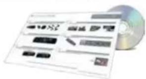
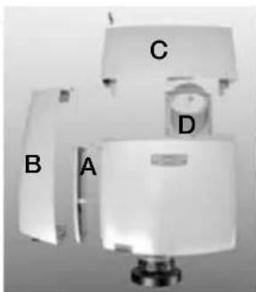
Additional accessories available for the projector:
Exhaust air kit (for ceiling mount):
A: Air-inlet filter (also sold separately)
B: Side cover/Air-inlet
C: Ceiling mount cover/Air-outlet (also sold separately)
D: Exhaust air duct*
*Flexible hose (2m) with clamp included
Acoustic silencer kit (for ceiling mount):
B: Side cover/Air-inlet
C: Ceiling mount cover/Air outlet
natural_image
Exterior view of a white mechanical device with labeled components A, B, C, D (no text or symbols beyond labels)Check that you have all components listed when unpacking the unit.

Please save packaging materials for future use, should it be necessary to ship the unit.
4 Installation
4.1 System considerations

Please refer to Chapter 5 Overview for an explanation on the various features of the projector.
Installation should only be performed by trained and skilled personnel in order to achieve the desired results.

Safety first: Projectors and other equipment that are not mounted properly represent a potential danger to people and may result in injury or death!
Creating a successful system installation requires proper skills, competencies and knowledge of the particular system requirements. In addition to knowing the expected performance, ambient conditions and all the components that form the complete system, including Image Generation (IG), cabling, control system, screens and projectors.
An installation often consists of multiple projectors, long cables and several IG's, as well as intermediate system components like signal converters and line buffers.
Make sure that:
- IG properties like pixel resolution and frame refresh match those of the projector
- Choice of signal interface and cable lengths match.
o HDBaseT and 3G-SDI are so called long-haul interfaces, suitable for bespoke installation on the premises using relatively long cables.
o DP, HDMI, DVI and VGA are all short-haul interfaces using pre-assembled cables with limited cable lengths. Using extended cable lengths may result in reduced image quality as well as loss of control information such as EDID (Extended Display Information Data).
- Signal amplifiers, switches and other components should convey EDID and other control information. However, unfortunately many times EDID data is lost in translation under way, potentially resulting in images of reduced pixel resolution and wrong aspect ratio.
A successful installation takes all relevant parameters into account to achieve great imagery!
4.2 Ventilation

Minimum safety distance to any side of the unit is 50cm / 20" in any direction.
Hot air is exhausted from the rear vent. Do not place objects that are sensitive to heat closer than 50cm / 20" to the exhaust vent.
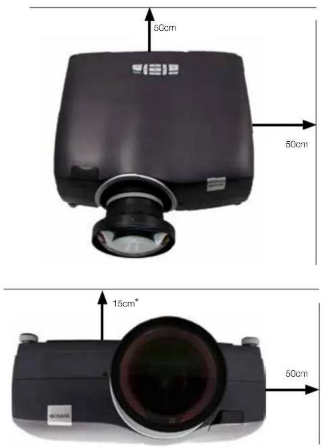
Figure 4-1. Positioning the projector
When the projector is ceiling mounted using an exhaust air kit* (accessory) the minimum distance between projector and roof is 15cm.
4.2.1 Ventilation accessories
A set of optional accessories is available for this projector, covering anything from cables and lenses to air flow parts and lens control. For information on availability, specifications and pricing, please refer to our web site: www.barco.com
4.3 Ceiling and rig mounting
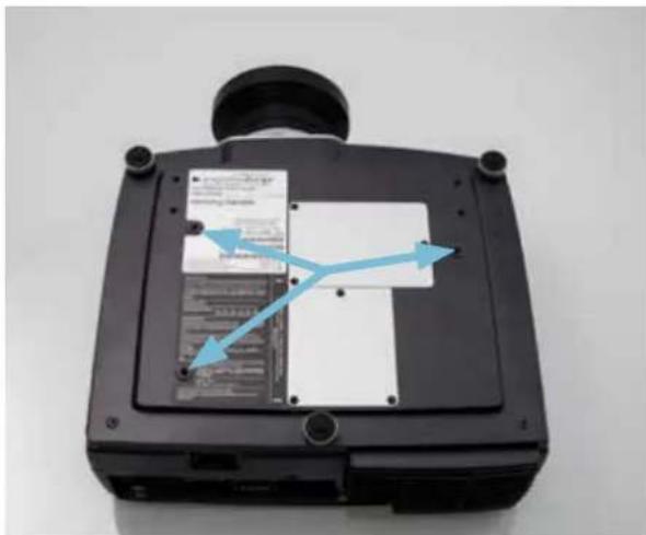
Use the three mounting holes provided in the bottom part to securely fix the projector to a ceiling or rig mount.
i
Use M6 screws that protrude maximum 9mm into the projector body.
natural_image
Black rectangular electronic device with a blue arrow pointing to internal components, no visible text or symbols on the device itself.Figure 4-2. Ceiling/rig mounting mounting holes
4.4 Locking the projector
The projector can be locked physically by using a so called Kensington lock. The Kensington lock hole, where the lock itself is attached, can be found on the back of the projector. Use an approved locking cable to secure the projector to a solid object.
4.5 Projector angle (tilt)
i
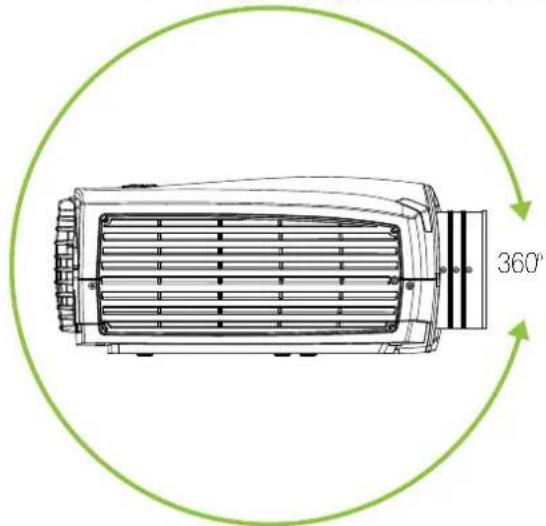
The projector should be tilted maximum +/- 20 degrees from level (flat/ceiling) position. It can be rotated 360 degrees around the lens axis.
!
Tilting at higher degrees may reduce lamp life and increase the probability of overheating the projector. Installation outside these specifications can void the guarantee.
natural_image
Technical line drawing of a mechanical component with a 360° rotation indicator (no text or symbols beyond the label)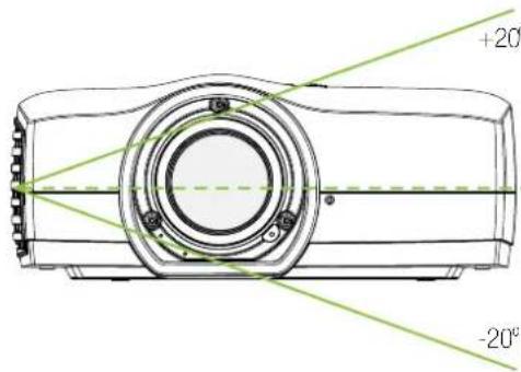
Figure 4-3. Tilting angles
4.6 Selecting a lens
The projector is delivered without a lens, enabling you to select a lens according to your desired image size and projection distance. The projector uses a bayonet mount system to precisely fix the lens in place. The lenses are manual, meaning zoom, focus and iris adjustments are done by hand manually. Lens shift is motorized (horizontally and vertically).
Use only the original projection lenses or lenses that have been approved for use with the projector.
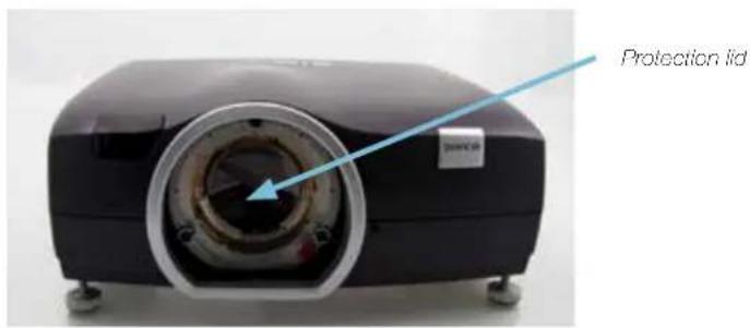
Figure 4-4. The protection lid
A protection lid is mounted on the projector lens opening to protect the interior of the projector from dust and damage. The protection lid must always be in place whenever there is no lens mounted on the projector!
The protection lid must be removed before attaching a lens!
The projection lenses are supplied with protection caps on both the entry and exit sides. Please keep the caps on until mounting the lens on the projector!
Remove lens protection caps before mounting the lens and using the projector.
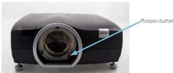
Figure 4-5. Projection lens release button
4.6.1 Inserting a lens
- Remove the protection lid on the projector by turning the lid anti-clockwise until it comes loose
- Remove the protection lids from the lens
- Insert the lens, making sure the red line marking on the lens points straight up towards the top of the cabinet. If the lens does not enter on the first attempt, retract the lens and try again from a slightly different angle. Do not use force!
- When the lens enters all the away in, firmly twist the lens clockwise until it clicks into position
4.6.2 Changing/removing a lens
- Press in the lens release button
- Twist the lens firmly anti-clockwise until it can be pulled gently out
- Remove the existing lens and put the 2 lens projection caps back on the removed lens
- Replace with another lens, or if no lens is to be installed, remount the projector protection lid

Note that the lens positioning when using lens shift may affect the accessibility of the lens button. If so, reposition the lens to gain access.
4.6.3 Lens range
The table shows a selection of lenses available. Please see www.barco.com for more information about lens availability.
| ITEM | TYPE | TH | ROW RATIO(WQXGA) | F# f (mm) | RANGE | (m) | SHIFT |
| EN51 | Zoom | 1.71- | 2.37:1 2.60-3.09 33.9 | 46.5 1.5-10 | Ver: 110% | Hor: 80% | |
| EN52 | Fixed | 0.99:1 | 2.60 19.7 1.0-10 Ver | 100% | Hor: 70% | ||
| EN53 | Fixed | 0.79:1 | @1.65 m 2.60 | 5.8 0.8-3.3 | Ver: 65% | Hor: 55% | |
| EN54 | Zoom | 2.68- | 4.18:1 2.60-3.26 52.6 | 81.5 5-25 | Ver: 110% | Hor: 80% | |
| EN55 | Zoom | 0.86- | 1.16:1 2.50-2.72 17.2 | 23.1 0.8-5.0 | Ver: 105% | Hor: 75% | |
| EN56 | Zoom | 1.14- | 1.74:1 2.50-2.72 22.8 | 34.7 1.3-7.0 | Ver: 105% | Hor: 75% |
4.7 Lens lock
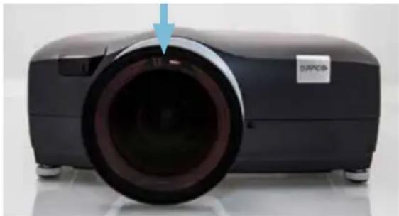
A lens-lock feature is available whereby three screws on the lens barrel are used to permanently fix the zoom, focus and iris positions. For information on locking the adjustment rings in one position, please refer to section 3.10 Zoom, focus and iris.
natural_image
Black industrial projector with visible lens and control buttons, no text or symbols on bodyFigure 4-6. Zoom and Focus Lens lock screws (one on each lens ring)
4.8 Lens shift
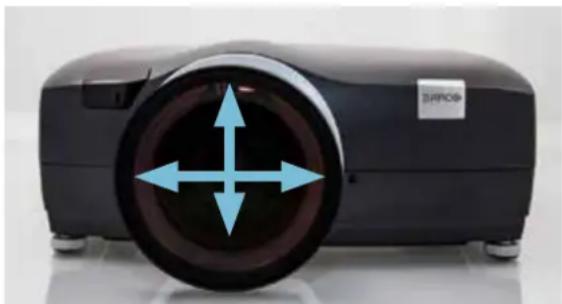
Most of the projection lenses are shiftable horizontally (both directions) and vertically (up). Some lenses, typically wide angle lenses (on-axis type) only have a very little shift range. Please refer to the individual lens specifications found on the web for actual shift range.
natural_image
Black projector with four blue directional arrows on the front wheel (no text or symbols visible)Figure 4-7. Horizontal (both directions) and vertical (up/down) lens shift
Lens shift is motorized and the lens can be shifted either by using the keypad, the wireless remote control or through the wired control interface. For an overview of the lens shift adjustment range for the various lenses, please refer to section 3.6.3 Lens range.
- Using the keypad on the projector, press OK and then OK again to center lens manually, or use the arrow keys to position (restricted downwards movability).
- Using the remote control, press the OK key to center the lens or arrow keys to position it (restricted downwards movability).
- Using the RS-232 or LAN control interfaces, please refer to the relevant SIS (Simplified Instruction Set) commands available for download on www.barco.com
4.9 Lens planarity (Scheimpflug adjustment)

This adjustment is rarely needed, do not apply it unless it is required.
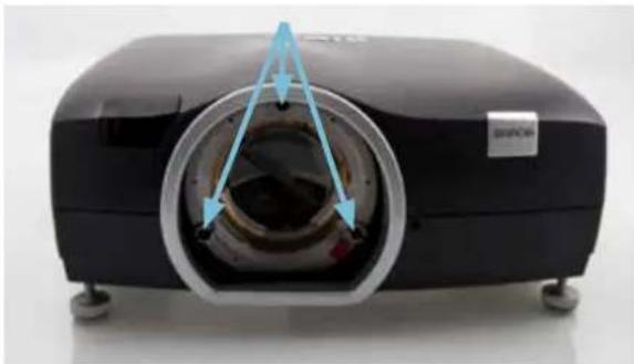
Certain applications require fine adjustment of the lens planarity in order to obtain an image that is focused. The projector is fitted with three adjustment screws (Allen key 3mm/5mm) around the bayonet mount that facilitate such adjustment, a so called Scheimpflug adjustment. Do not attempt adjusting without the required technical competence and refer to the service manual found on our web for further info.
natural_image
Black projector with visible lens and control panel, no text or symbols presentFigure 4-8. Scheimpflug Adjustment Screws
4.10 Zoom, focus and iris
These lens functions are manual (not motorized).
- First adjust zoom to achieve the desired image size (if the lens has a zoom-function).
- Then adjust focus to achieve a sharp image. If the image is not sharp all over the surface, please check the surface flatness and whether the lens axis is perpendicular to the projection surface.
- Use the iris to adjust the contrast and focus depth of the image. Adjusting the iris will affect the brightness; stopping the iris down increases contrast and image depth, but reduces brightness.
- The zoom, focus and, iris rings can be locked in position for typical motion based installations to secure that the picture settings are not changed. Tighten the pre-installed M3 screws on each ring to lock the movement, using a 1.5mm Allen key, until the rings can not be turned.
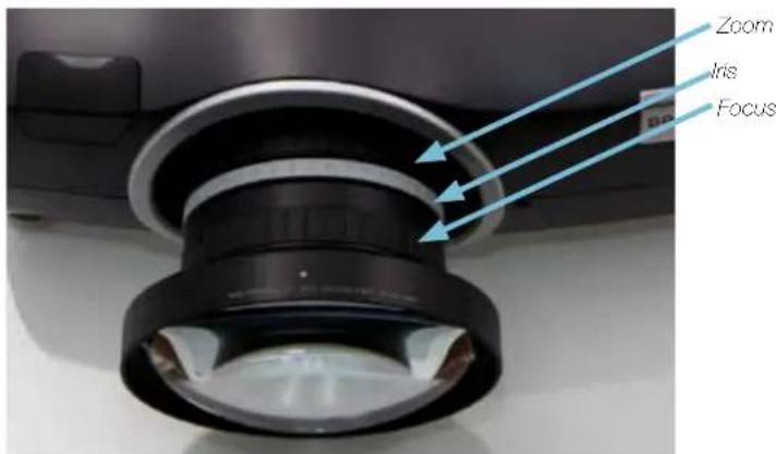
Figure 4-9. Positioning of Zoom, Focus and Iris rings (may vary on some lenses)
4.11 Making the connections
The projector is equipped with multiple signal and control interfaces to support various video and data sources (see connector panel below), as well as different control systems.
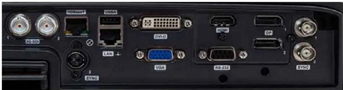
Always make sure that the projector is powered off before connecting any signal and/or control cables.
Long cables may cause distorted or even failing signal quality. Always make sure best quality cables are used, and take into consideration the cable length limitations applying to the various interface standards.
4.12 Connecting video and data sources
Choice of connectivity depends on the installation requirements as well as the sources connected. Generally, digital interfaces are preferred over analog. Multiple signals can be connected in parallel to allow for a selection of sources to be viewed in sequence.
Attach the interfaces of choice and make sure all connectors are fully inserted and retained.
4.13 Connecting control interfaces
Power off the projector and the source!
Choice of control interface depends on the installation requirements. Attach the interfaces of choice and make sure all connectors are fully inserted and retained.
Please see the relevant SIS (Simplified Instruction Set) commands available for download on www.barco.com for easy access to more information.
Power up the projector and the source!
4.14 Source format integrity – EDID
If using 3rd party system equipment, such as signal repeaters or switchers, please make sure that EDID (Extended Display Identification Data) information is not lost in translation. Wrong EDID data may result in distorted images, wrong aspect ratios or reduced image resolutions.
4.15 Image sizes
1920 x 1200/1920 x1080 (WUXGA/1080)
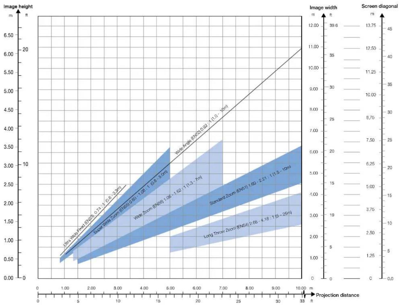
line
| Projection distance (m) | Ultra Wide Fixed (EN53) | Super Wide Zoom (EN53) | Wide Zoom (EN53) | Standard Zoom (EN51) | Long Throw Zoom (EN54) | | ----------------------- | ------------------------ | ------------------------ | ----------------- | ---------------------- | ------------------------ | | 0 | 0.5 | 0.5 | 0.5 | 0.5 | 0.5 | | 1.0 | 1.0 | 1.0 | 1.0 | 1.0 | 1.0 | | 2.0 | 1.5 | 1.5 | 1.5 | 1.5 | 1.5 | | 3.0 | 2.0 | 2.0 | 2.0 | 2.0 | 2.0 | | 4.0 | 2.5 | 2.5 | 2.5 | 2.5 | 2.5 | | 5.0 | 3.0 | 3.0 | 3.0 | 3.0 | 3.0 | | 6.0 | 3.5 | 3.5 | 3.5 | 3.5 | 3.5 | | 7.0 | 4.0 | 4.0 | 4.0 | 4.0 | 4.0 | | 8.0 | 4.5 | 4.5 | 4.5 | 4.5 | 4.5 | | 9.0 | 5.0 | 5.0 | 5.0 | 5.0 | 5.0 | | 10.0 | 5.5 | 5.5 | 5.5 | 5.5 | 5.5 | | 11.0 | 6.0 | 6.0 | 6.0 | 6.0 | 6.0 | | 12.0 | 6.5 | 6.5 | 6.5 | 6.5 | 6.5 | | 13.0 | 7.0 | 7.0 | 7.0 | 7.0 | 7.0 | | 14.0 | 7.5 | 7.5 | 7.5 | 7.5 | 7.5 | | 15.0 | 8.0 | 8.0 | 8.0 | 8.0 | 8.0 | | 16.0 | 8.5 | 8.5 | 8.5 | 8.5 | 8.5 | | 17.0 | 9.0 | 9.0 | 9.0 | 9.0 | 9.0 | | 18.0 | 9.5 | 9.5 | 9.5 | 9.5 | 9.5 | | 19.0 | 10.0 | 10.0 | 10.0 | 10.0 | 10.0 | | 20.0 | 10.5 | 10.5 | 10.5 | 10.5 | 10.5 | | 21.0 | 11.0 | 11.0 | 11.0 | 11.0 | 11.0 | | 22.0 | 11.5 | 11.5 | 11.5 | 11.5 | 11.5 | | 23.0 | 12.0 | 12.0 | 12.0 | 12.0 | 12.0 | | 24.0 | 12.5 | 12.5 | 12.5 | 12.5 | 12.5 | | 25.0 | 13.0 | 13.0 | 13.0 | 13.0 | 13.0 | | Note: The projection distance is labeled as "projection distance". The image height is shown on the left y-axis in meters (ft) and the screen width is on the right y-axis in meters (m). The angle of view is calculated based on the projection distance and the image width is calculated using the screen diagonal.Lens types and specifications may change without prior notice. For correct lens information please refer to www.barco.com
2560 x 1600/ 2560x1080 (WQXGA/Panorama)
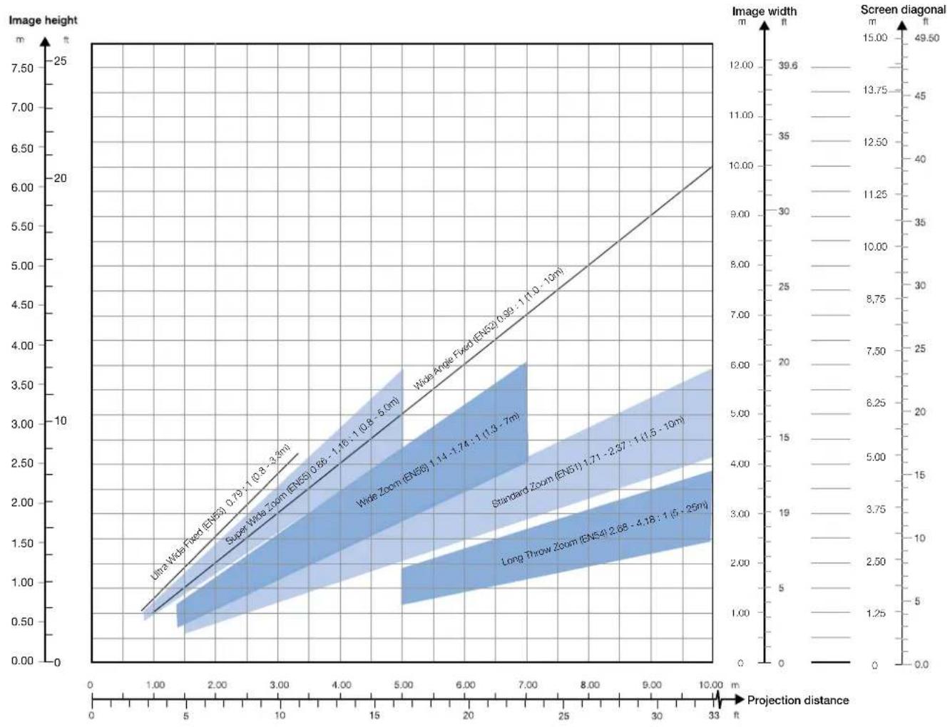
line
| Projection distance | Ultra Wide Fixed (EN5) | Super Wide Zoom (EN5) | Wide Zoom (EN6) | Standard Zoom (EN5) | Long Throw Zoom (EN5) | | ------------------- | --------------------- | --------------------- | --------------- | ------------------- | --------------------- | | 1.00 | 0.75 | 0.8 | 1.14 | 1.71 | 2.68 | | 3.00 | 1.75 | 1.8 | 2.37 | 3.27 | 4.18 | | 5.00 | 2.75 | 2.8 | 3.7 | 5.0 | 6.2 | | 7.00 | 3.75 | 3.8 | 5.0 | 7.0 | 8.7 | | 10.00 | 5.0 | 5.1 | 7.0 | 10.0 | 12.5 | | 33.00 | - | - | - | - | - |
Lens types and specifications may change without prior notice.
For correct lens information and other resolutions please refer to www.barco.com
5 Overview
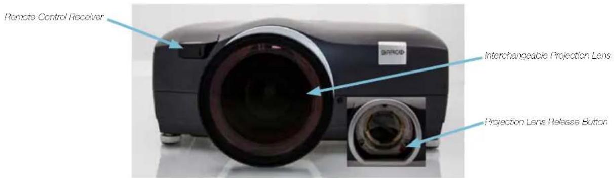
Figure 5-10. Projector front
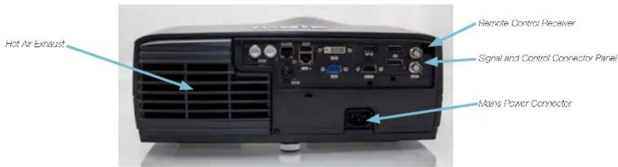
Figure 5-11. Projector rear
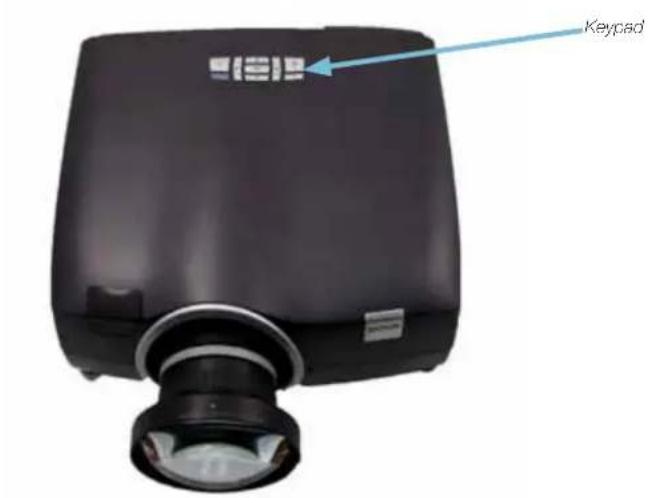
Figure 5-12. Projector top
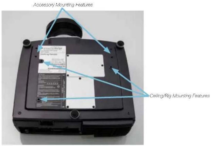
Figure 5-13. Mounting features
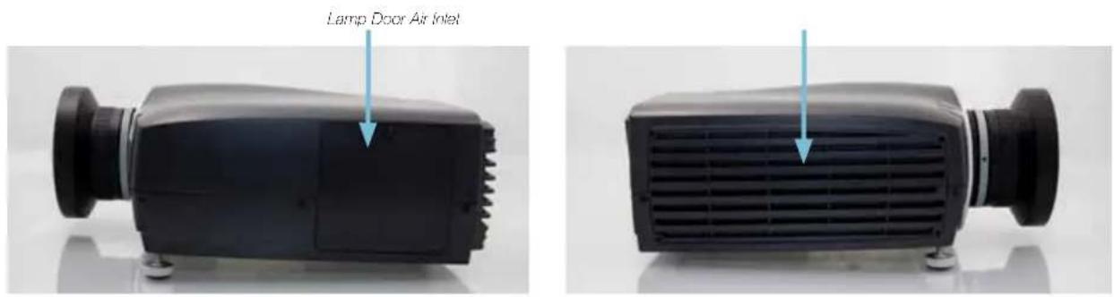
Figure 5-14. Projector left and right hand side
5.1 Keypad and indicator
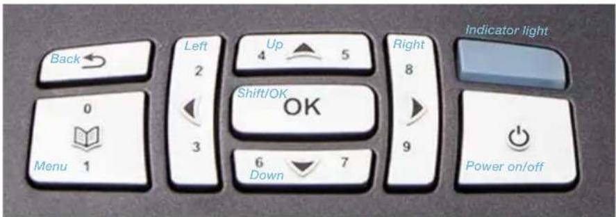
Figure 5-15. Projector top key pad
| KEY VALUE | |
| POWER Power on or power | off (standby) |
| MENU Activate or deactivate | on-screen menu system |
| UP, DOWN, LEFT, RIGHT Select | select source when not in Shift or Menu modeShift lens when not in Menu and after SHIFT/OK pressedNavigate when in Menu system |
| SHIFT/OK Shift lens when not in menu systemShift option when in menu system | |
| AUTO Automatic set-up | |
| STATUS COLOR | |
| On (active) | Blue |
| Wait on Blue flashing | |
| Standby (off) Yellow | |
| Wait Yellow flashing | |
| Lamp failure Red | |
| Overheating Red flashing | |
| Configure/upgrade | Yellow fast flashing |
| Error | Red fast flashing |
5.2 Wireless remote control
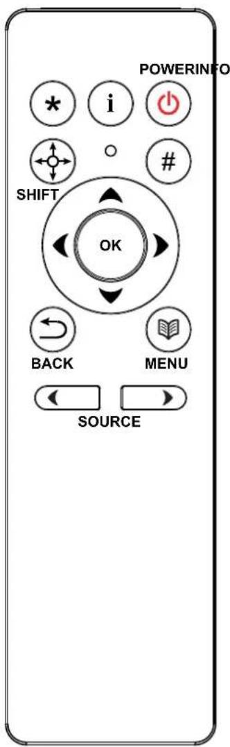
Batteries can be replaced by end-user. To replace the 2 standard AAA batteries for this remote control, slide the lid at the back of the control downwards. Lift it off and remove the batteries. Replace with new batteries and slide the lid back in place.
Figure 5-16. Remote control
| BUTTON FUNCTION | |
| POWER Turns projector ON/OFF | |
| INFO Shows Status menu; info on numbers & versions, lamp info | |
| * | Activates the projector auto settings |
| SHIFT Activates lens shift function | |
| # | Reserved for future use |
| OK/ARROWS Confirms the selection / Directional navigation tools | |
| BACK Returns to previous alternative | |
| MENU Activates the projector menu | |
| SOURCE Toggles between available sources (forward/backwards arrows) | |
5.3 Connectors
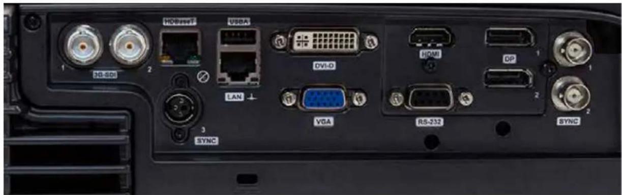
Figure 5-17. Connector panel (see technical data for details)
5.3.1 Signal connectors
| CONNECTOR NAME | CONNECTOR TYPE | FUNCTION |
| HDBaseT RJ45 V | deo over twisted pair | |
| DVI DVI-I*) dual link | Digital video (dual-link) | |
| HDMI HDMI type A | Digital video | |
| DP (DisplayPort) DP | Digital video (2) | |
| VGA 9 pin mini DSUB | Analog RGBHV video | |
| 3G-SDI BNC 75 Ω | Digital Video |
*) the DVI connection is digital-only, although it uses the DVI-I physical connector for convenience
5.3.2 Control connectors
| CONNECTOR NAME | CONNECTOR TYPE | FUNCTION |
| SYNC1 BNC | Multi purpose | se bi-directional synchronization port |
| SYNC2 BNC | Multi purpose | se bi-directional synchronization port |
| SYNC3 3-pin mini-DIN | Powered multi purpose bi-directional synchronization port | |
| USB A | USB A | USB connectors for SW upgrade and diagnosis |
| LAN | RJ45 | Control |
| RS232 9 PIN DSUB | Control | |
5.4 Menu system
The various projector-settings can be controlled via the on-screen menu system. The menu system is accessed by the keypad on the projector or using the wireless remote control.
Press the MENU key to enter or leave the menu system. Navigate the options using the arrow-keys. Select option with the OK key.
The menu-system will be referenced throughout the user guide. Please familiarize yourself with the menus and the rich functionality provided.
5.4.1 Top menu

3D: 3D and dual head setup
picture: Basic and advanced picture controls.
installation: System controls and information.
settings: Settings that affect how the projector behaves or interacts with third party devices, such as networks and control systems
language: Selects menu language.
status: System information.

The top level menu item 3D is only visible for Active Stereo 3D enabled projectors.
5.5 3D main menu
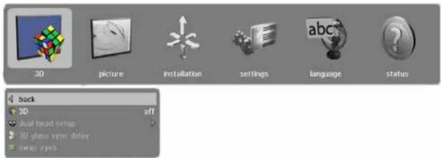
The 3D menu contains settings for turning 3D on and off, in addition to defining various aspects of setup using Dual Head and specifying the types of glasses to be used.
3D : Offers the possibility to switch the 3D function off and to chose between the following alternatives for setup: off, side by side (<60Hz only), frame sequential and dual head (<60Hz only)
dual head setup: Allows the user to select left eye and right eye input sources. Some combinations of left/right eye are not possible, see table on next page.
3D glass sync delay: Here you can set the delay time for your 3D glasses on a range from 0-359°
swap eyes: Swap order of eyes (left/right) for 3D-glass synchronization.
5.5.1 3D > Dual head setup sub menu
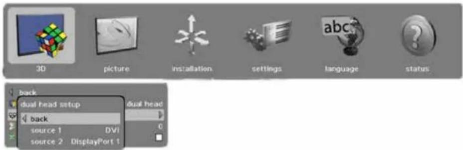
source 1: Choice of source. Alternatives are SDI1, SDI2, DVI, HDMI, VGA, HDBaseT, DisplayPort1, DisplayPort 2. For possible setup combinations, see Figure 5-18. Dual head setup possibilities.
source 2: Choice of source. Alternatives are SDI1, SDI2, DVI, HDMI, VGA, HDBaseT, DisplayPort1, DisplayPort 2. For possible setup combinations, see Figure 5-18. Dual head setup possibilities.
| DP1 | DP2 | HDBaseT | DVI(SL) | HDMI | DVI (DL) | VGA | 3G SDI (A) | 3 G SDI (B) | |
| DP1 | |||||||||
| DP2 | |||||||||
| HDBaseT | |||||||||
| DVI (Single Link Mode) | |||||||||
| HDMI | |||||||||
| DVI (Dual Link Mode) | |||||||||
| VGA | |||||||||
| 3G SDI (A) | |||||||||
| 3G SDI (B) |
| Not possible | |
| Possible |
Figure 5-18. Dual head setup possibilities
5.6 Picture main menu

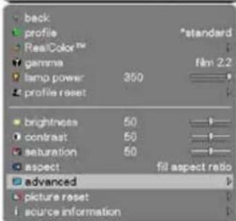
The picture menu contains basic and advanced settings and adjustments for detailed picture enhancement control. All adjustments are global and are stored independently of source. The exception is 2D/3D for which the profiles are stored individually.
profile:
A selection of predefined profiles with different attributes: standard, presentation, bright, video, cinema, DICOM, SRP, custom, advanced (only available if enabled from service menu). If the profile is marked by an asterisk (*), this indicates that the original settings have been changed.
RealColor:
Barco's proprietary color management suite. See description in RealColor sub menu.
gamma: 10 predefined gamma curves:
Film 2.2: Exponential 2.2 curve
Film 2.4: Exponential 2.4 curve
Film 2.6: Exponential 2.6 curve
Film 2.8: Exponential 2.8 curve
Video 1: Relaxed S-shape
Video 2: Increase S-shape
Computer 1: Steep S-shape
Computer 2: Very steep S-shape
Dynamic: Increase S-shape
DICOM 180 Lux: Curve shape depending on type of color wheel used. When entering DICOM profile there are more DICOM gamma curves, for instance DICOM 10 Lux and DICOM 400 Lux
lamp power: Adjustment of lamp power between 280-350W
profile reset: Resets any entered profiles, either current or all, to default
brightness: Electronic image brightness. Range -50 to +50
contrast: Electronic image contrast. Range -50 to +50
saturation: Electronic image saturation. Range -50 to +50
aspect: Aspect ratio of image scaling. 5 options:
Fill aspect ratio: Fills the imaging device in horizontal and/or vertical direction to main the input image aspect ratio.
Fill all: Fills the entire imaging device regardless of the input aspect ratio and resolution.
Fill 16:9: Fills the imaging device with a 16:9 aspect ratio (scaled) image regardless of input aspect ratio and resolution.
Fill 4:3: Fills the imaging device with a 4:3 aspect ratio (scaled) image regardless of the input aspect ratio and resolution.
One-to-one: Shows the input image mapped pixel-by-pixel without scaling on the imaging device.
advanced: Advanced features. See Chapter 5.6.2.
reset: Restore picture settings to factory default.
source information: Detailed information about the acquired source.
5.6.1 Picture > RealColor sub menu
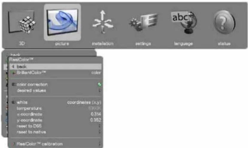
BrilliantColor™:
Texas Instruments DLP™ color processing. 3 settings*:
Bright: Max brightness, boosted color profile for highest perceived brightness. In this mode all segments and spokes of the color wheel are in use.
Color: Max brightness, balanced color profile for better color performance. In this mode all segments and spokes of the color wheel are in use.
Auto: Only available in 3D
* In advanced profile additional BC modes:
- Color (rgb only), bright (rgb only),
- SRP Half (rgb only), SRP Full (rgb only)
Off: In this mode the spokes (transition between segments) and all secondary segments (cyan and white) and on color wheel are off. Less color and brightness boost will reduce image noise.
SRP™ Half: Smear Reduction Processing (half revolution), wiz zim/wiz zim bright only
SRP™ Full™: Smear Reduction Processing (full revolution), wiz zim/wiz zim bright only
color correction: Enable or disable color correction.
desired values:
Desired coords mode (RGB, RGBCMY) for RealColor and specification of red, green blue, cyan, magenta, yellow and white (if in coordinates mode) coordinates (x,y) color and gain.
Reset all to native: Resets all to measured values/projector native)
white
Decides which method to be used for setting of the white point; temperature of x-/y-coordinate.
temperature:
Sets the system color temperature (white point) on the Kelvin scale from 3200K to 9300K in steps of 100K. All color temperatures are tracked on the black body curve. The exact coordinates for the temperature will be shown in coordinates (x,y) when adjusting the temperature.
x-coordinate: Sets the X co-ordinate of the white point.
y-coordinate: Sets the Y co-ordinate of the white point.
reset to D65: Reset the white point to D65 coordinates.
reset to native: Resets white point to measured values.
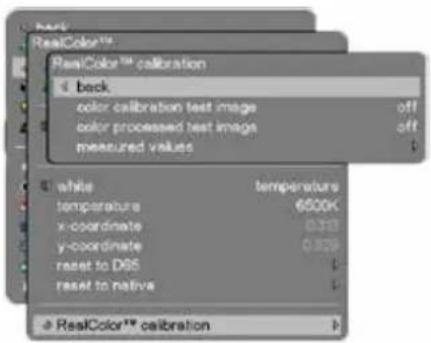
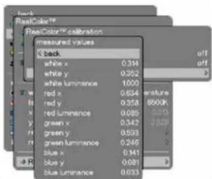
RealColor calibration:
Selects color calibration test images (off, uncorrected red/green/blue/full white) and color processed test images (red, green, blue, white, black, cyan, magenta, yellow). Presents measured values for RealColor (see below). Calibration settings have to be made individually for each separate profile.
5.6.2 Picture > Advanced sub menu

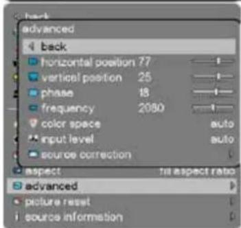
horizontal position: Shifts the image sideways (VGA only)
vertical position: Shifts the image up or down (VGA only)
phase: Adjust for stable image. A jittery image may appear with certain VGA sources.
You may also press the AUTO button on the keypad or remote control to optimize.
frequency: Adjust image width. An incorrect setting may produce vertical, unstable bands
in the image, and parts of the image may not be displayed on screen. Push the AUTO button to find a correct setting, or manually adjust the frequency until the vertical bands disappear. Frequency adjusts the pixel clock sampling frequency
color space: Enables selecting between Auto, RGB, YCbCr 601, YCbCr 709
input level: Choice between; auto, computer, video. Depending on source select between 0-255 (computer), 16-235 (video).
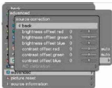
source correction: Gives access to individual brightness offset settings (see below).
In addition you can start the AD calibration process which requires VGA source which displays a Grey16 image (right hand image below).

natural_image
Gradient grayscale image with vertical bands of varying shades from dark to light (no text or symbols)5.7 Installation main menu

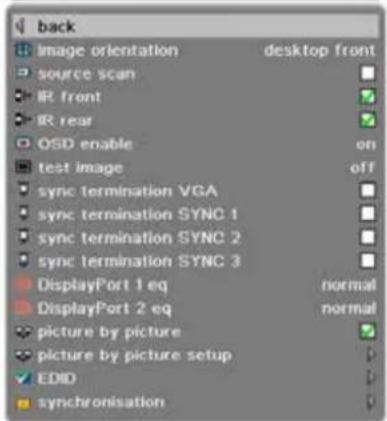
image orientation: Rotate the image on the imaging device in desktop front, desktop rear, ceiling front, ceiling rear.
source scan: Search through all input connectors for an active signal or stay on one connector.
IR front Enable or disable front IR-receiver.
IR rear Enable or disable rear IR-reciever.
OSD enable: Sets how the OSD messages should appear.
On: All OSD messages are shown.
Only warnings: Only critical OSD messages are shown.
Off: No OSD messages are shown. The OSD menu is still accessible by clicking menu on either the remote or the keypad.
test image: Displays internal test images for projector alignment and setup. Option to show 4:3, 16:9, 16:10, 1.85:1, 2.35:1, 5:4, combined, off
4:3: fills the imaging device with a white image, but marks out the 4:3 area in the center of the image.
16:9: fills the imaging device with a white image, but marks out the 16:9 area in the center of the image.
16:10: fills the imaging device with a white image, but marks out the 16:10 area in the center of the image.
1.85:1: fills the imaging device with a white image, but marks out the 1.85:1 area in the center of the image.
2.35:1: fills the imaging device with a white image, but marks out the 2.35:1 area in the center of the image.
5:4: fills the imaging device with a white image, but marks out the 5:4 area in the center of the image.
Combined: fills the imaging device with a white image and marks out the all of the above aspect ratios.
sync termination VGA: Enable sync termination to 75 Ω /2.2 kΩ
sync termination SYNC1: Enable sync termination to 75 Ω /2.2 kΩ
sync termination SYNC2: Enable sync termination to 75 Ω /2.2 kΩ
sync termination SYNC3: Enable sync termination to 75 Ω /2.2 kΩ
DisplayPort 1 eq Choice between Normal, High, Low (enables receiving signals via longer cables/with higher bit rate)
DisplayPort 2 eq Choice between Normal, High, Low (enables receiving signals via longer cables/with higher bit rate)
picture by picture Show two sources side by side
picture by picture setup Choose the two sources to be shown side by side
EDID: Sub menu for EDID, see chapter 5.7.1.
synchronization: Sub menu for synchronization see chapter 5.7.2.
5.7.1 Installation > EDID sub menu
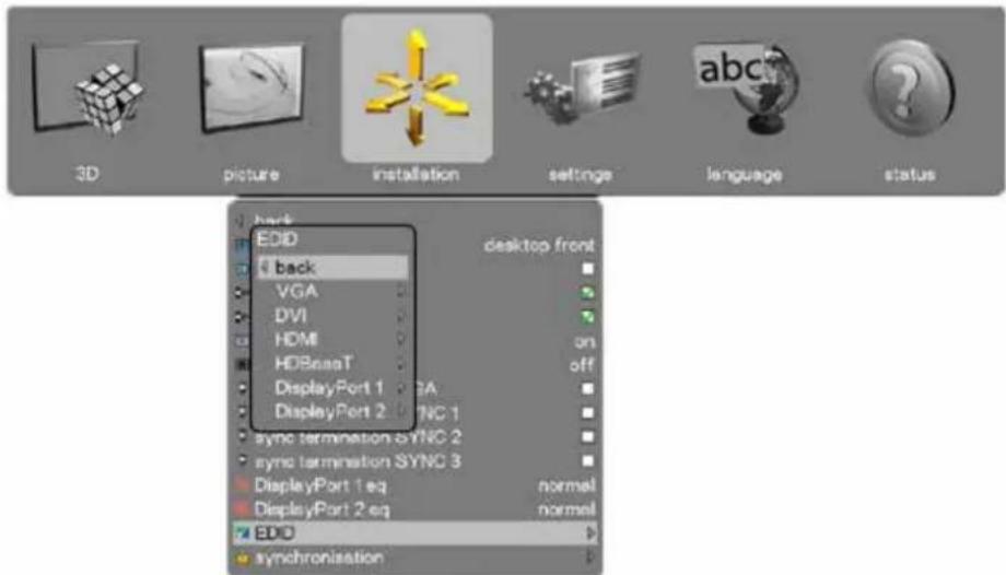
VGA: Define the detailed timing descriptor in the EDID data for VGA connector. Select between auto, WUXGA, 1080@60Hz, SX+, SXGA, 1366x768, 720@60Hz, 720@50Hz, XGA, SVGA, VGA.
DVI: Define the detailed timing descriptor in the EDID data for DVI connector. Select between auto, WQXGA@60Hz, WUXGA@120Hz, WUXGA@60Hz, 1080 @120Hz, 1080@60Hz, SX+, SXGA, 1366x768, 720@60Hz, 720@50Hz, XGA, SVGA, VGA. Here are the auto-settings for various projectors: • 1080 projector: 1920x1080@120 Hz. Dual link • WUXGA projector: 1920x1200@120 Hz. Dual link • WQXGA projector: 2560x1600@60 Hz. Dual link
HDMI: Define the detailed timing descriptor in the EDID data for HDMI connector. Select between auto, WUXGA@60Hz, 1080 @60Hz, SX+, SXGA, 1366x768, 720@60Hz, 720@50Hz, XGA, SVGA, VGA. All settings, except auto, uses DVI as type. Here are the auto-settings for various resolutions: • 1080 projector: 1920x1080@60 Hz • WUXGA projector: 1920x1200@60 Hz • WQXGA projector: 1920x1200@60 Hz
HDBaseT: Define the detailed timing descriptor in the EDID data for HDBaseT connector. Select between auto, WUXGA@60Hz, 1080@60Hz, SX+, SXGA, 1366x768, 720@60Hz, 720@50Hz, XGA, SVGA, VGA. All settings, except auto, uses HDMI as type. Here are the auto-settings for various resolutions: • 1080 projector: 1920x1080@60 Hz • WUXGA projector: 1920x1200@60 Hz • WQXGA projector: 1920x1200@60 Hz
DisplayPort 1: Define the detailed timing descriptor in the EDID data for DisplayPort 1 connector. Select between auto, WQXGA@120Hz, WQXGA@60Hz, WUXGA@120Hz, WUXGA@60Hz, 1080@120Hz, 1080@60Hz, SX+, SXGA, 1366x768, 720@60Hz, 720@50Hz, XGA, SVGA, VGA. Here are the auto-settings for various resolutions: • 1080 projector: 1920x1080@120 Hz • WUXGA projector: 1920x1200@120 Hz • WQXGA projector: 2560x1600@120 Hz
DisplayPort 2: Define the detailed timing descriptor in the EDID data for DisplayPort 2 connector. Select between auto, WQXGA@60Hz, WUXGA@120Hz, WUXGA@60Hz, 1080@120Hz, 1080@60Hz, SX+, SXGA, 1366x768, 720@60Hz, 720@50Hz, XGA, SVGA, VGA. Here are the auto-settings for various resolutions: • 1080 projector: 1920x1080@120 Hz • WUXGA projector: 1920x1200@120 Hz • WQXGA projector: 2560x1600@60 Hz
* In addition to the listed options there are the following options available for Picture by Picture usage: 960x1080@60 Hz/120 Hz, 960x1200@60 Hz/120 Hz, 1280x1600@60 Hz/120 Hz - depending on projector model.
5.7.2 Installation > Synchronization sub menu
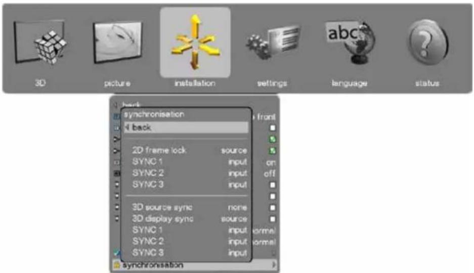
| 2D frame lock: | Selects the 2D frame lock sync signal. Options for 2D frame lock: source, SYNC 1, SYNC 2, SYNC 3. |
| SYNC 1: | Selects usage of SYNC1 connector in 2D mode. Options for SYNC 1: input, display sync, SYNC 2, SYNC 3 |
| SYNC 2: | Selects usage of SYNC2 connector in 2D mode. Options for SYNC 2: input, display sync, SYNC 1, SYNC 3 |
| SYNC 3: | Selects usage of SYNC3 connector in 2D mode. Options for SYNC 3: input, display sync, SYNC 1, SYNC 2 |
| 3D source sync: | Selects the 3D source LR sync signal. Options for 3D source sync: source, SYNC 1, SYNC 2, SYNC 3 |
| 3D display sync: | Selects the 3D display LR sync signal. Options for 3D source sync: source, SYNC 1, SYNC 2, SYNC 3 |
| SYNC 1: | Selects usage of SYNC1 connector in 3D mode Options for SYNC 1: input, display sync, glass sync, SYNC 2, SYNC 3 |
| SYNC 2: | Selects usage of SYNC2 connector in 3D mode Options for SYNC 2: input, display sync, glass sync, SYNC 1, SYNC 3. |
| SYNC 3: | Selects usage of SYNC3 connector in 3D mode Options for SYNC 3: input, display sync, glass sync, SYNC 1, SYNC 2 |

If you use one of the sync connectors as 2D or 3D sync input, this may block the use of the same connector as output.
For further info on the various possible user scenarios, please refer to our web page.
5.8 Settings main menu

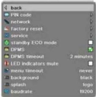
PIN code: Protect the projector from usage with a PIN. If enabled the projector will ask for the PIN at every start up.
network: Set IP address, Subnet mask and default gateway TCP/UDP port number. DHCP is supported and is enabled by default, but can be disabled.
factory reset: Restore all settings to the factory defined values.
service: End user protected settings. Access PIN code required.
standby ECO mode Power saving mode sending the projector into a deep sleep setting when in standby. Wake up can be performed either by pressing the power button on the projector/remote control or remotely via the RS232 connector using the ASCII protocol / wake on LAN via the ethernet. If DPMS is enabled and a source signal becomes active again the projector will return to normal operation. When in standby ECO mode, the baudrate of the RS232 communication is fixed at 19200.
DPMS: Enable or disable DPMS power saving. This feature is used to automatically power down the projector if no source is detected for a given period of time (defined by DPMS timeout). If the projector is powered down in DPMS power save, it will automatically power back on if a valid source is acquired.
DPMS timeout: Set the period of time before the projector automatically enters DPMS mode. DPMS must be enabled for this menu item to activate.
LED indicators mute: Disable all LED indicators on top of the projector. A critical error (status LED flashing RED) will still be enabled.
menu timeout: The time interval before the OSD is automatically disabled. Option of "never" is available if the OSD is never to time out.
background: Gives a choice between white, gray or black background color.
splash: Possibility to choose between logo or black for the startup splash screen.
baudrate: Presents alternative bauderate settings: 4800, 9600, 19200, 38400, 57600, 115200
5.8.1 Settings > Pin Code sub menu
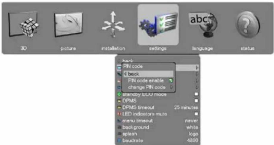
PIN code enable:
The PIN code is disabled by default. If you want to enable/disable the PIN code you have to enter the current PIN (Default PIN: 1234). When completed you can enable or disable the use of PIN code. If PIN is entered incorrectly 3 times, it will ask for a PUK code, which is provided in printed form in the box. If the PUK is entered incorrectly it will require a special unlock code provide by a service partner to unlock the projector.
change PIN code:
To change the PIN code you first have to enter the current PIN code (Default PIN: 1234). Then you enter a new 4 digit code and confirm this code by entering the same code again. Click OK and the new code is set.
5.8.2 Settings > Network sub menu
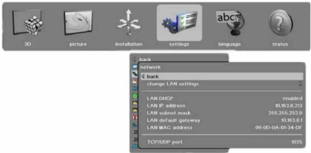
change LAN settings: In this sub-menu you can switch the DHCP enabled function on or off. If off you can set a fixed IP-address.
LAN DHCP: DHCP is supported and is enabled by default, but can be disabled under change LAN settings
LAN IP address: Info field stating the current LAN IP address.
LAN subnet mask: Info field stating the current LAN subnet mask.
LAN default gateway: Info field stating the current LAN default gateway.
5.8.3 Settings > Factory Reset sub menu
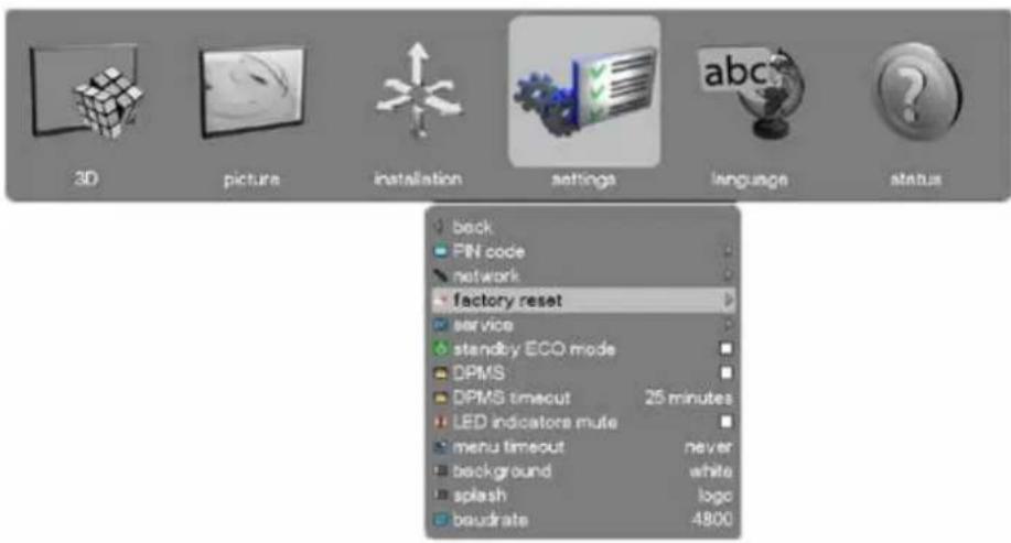
picture: Restores picture settings to factory default.
3D: Restores 3D settings to factory default.
communication: Restores communication settings to factory default.
RealColor ^TM : Restores RealColor ^TM settings to factory default.
other: Restores other settings of your choice to factory default.
5.8.4 Settings > Service sub menu
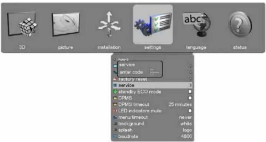
service: Restricted area with information intended for qualified service personnel only
enter code: Enter the 5-digit access code to gain assess to the service information.
5.9 Languages main menu
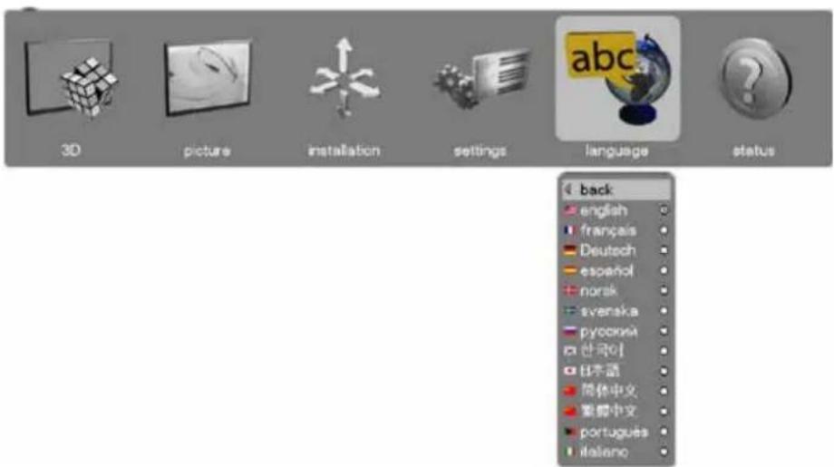
Select the desired menu language.
• Supported languages: English, French, German, Spanish, Norwegian, Swedish, Russian, Korean, Japanese, Chinese Traditional, Chinese Simplified, Portuguese, Italian.
- Default: English
5.10 Status main menu
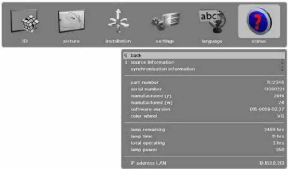
source information: Simple and advanced source information.
synchronisation
information: Displays the current synchronization information. Includes 2D framelock, 3D source sync and 3D display sync.
part number: Projector part number.
serial number: Projector serial number.
manufactured (y): Year of manufacturing.
manufactured (w): Week of manufacturing.
software version: Software version installed in the projector. This is very important for service requests.
colorwheel: Type of colorwheel installed.
lamp remaining: Remaining lamp time.
lamp time: Lamp time used.
total operating: Total operating time for projector.
lamp power: Lamp power in watts.
IP address LAN: Projector LAN IP address for use in network/remote control.
5.10.1 Status > Source Information sub menu
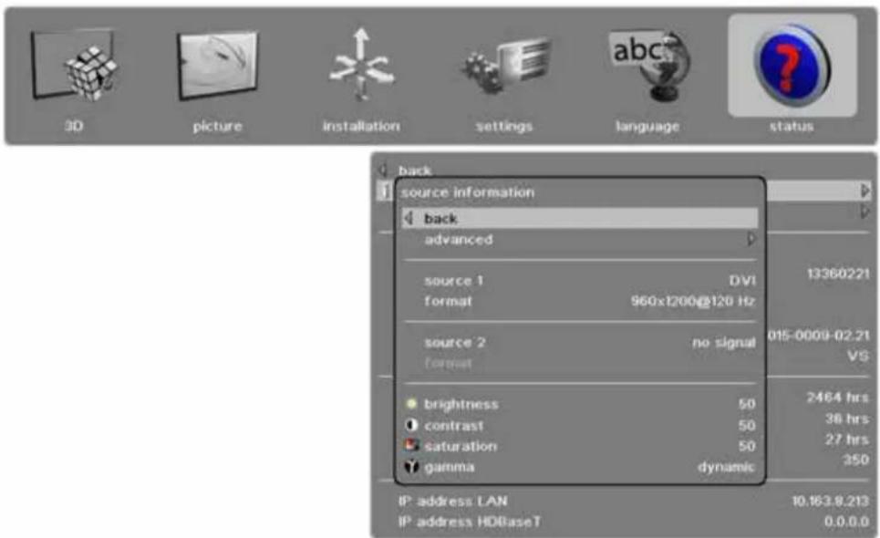
advanced: Access to sub menu for more settings depending on source used. See 4.10.2 Status > Source Information > Advanced sub menu
source 1: Info on which source is in use.
format: Displays resolution and frequency for the source in use.
source 2: Info on which source is in use.
format: Displays resolution and frequency for the source in use.
brightness: Info on brightness settings.
contrast: Info on contrast settings.
saturation: Info on saturation settings.
gamma: Info on gamma-variant used.
5.10.2 Status > Source Information > Advanced sub menu
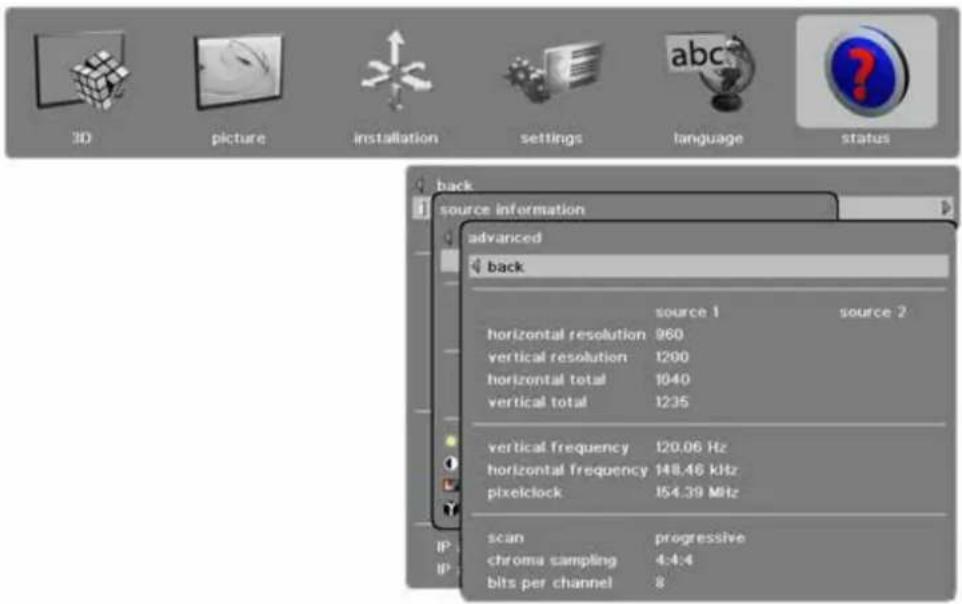
resolution: Info on current source resolution.
total image size: Info on current horizontal and vertical image size.
sync frequency : Info on current horizontal and vertical sync frequency for the projector.
pixelclock: Week of manufacturing.
scan: Projector serial number.
mode id: Info on current mode setup (VGA source only).
croma sampling: The current source croma sampling type. Typically 4:4:4 or 4:2:2.
bits per channel: The number of bits per channel. For instance, for a 24 bit RGB source, the number of bits per channel is 8.
5.10.3 Status > Source Synchronisation sub menu
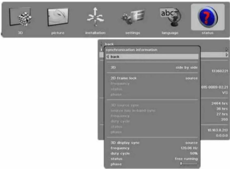
3D: Indicates which 3D mode is used.
2D frame lock: Indicates what the projector locks to in 2D
frequency: Shows the current frequency of the locking signal
status: Indicates the locking status
phase: Indicates phase between the source and the locking signal
3D source sync: Indicates where the source L/R sync is connected
source has in-band sync: Indicated if the source has embedded L/R sync, only supported on DisplayPort
frequency: Shows the current frequency of the signal
duty cycle: Shows the duty cycle of the signal
status: Indicates the sync status
phase: Indicates phase between the source and the L/R sync signal
3D display sync: Indicates what the projector locks to in 3D
frequency: Shows the current frequency of the locking signal
duty cycle: Shows the duty cycle of the signal
status: Indicates the locking status
phase: Indicates phase between the source and the locking signal
6 Functionality
The various functions of the projector are described in detail in the following chapters.
6.1 Powering On and Off
6.1.1 Manual power control
Switch the projector between On and Standby using the POWER switch on the keypad or the wireless remote control.
The keypad STATUS indicator is blue when the projector is up and running, flashing yellow when cooling down and yellow when in standby. No status light indicates that the power has been switched off completely in the installation.
6.1.2 DPMS - power down
This is a power down mode which needs to be activated in the SETTINGS menu. When activated it powers down after a specified period of time after a source has been removed. The time out setting can be specified in the DPMS TIMEOUT function in the same menu, using the arrow keys.
6.2 Image alignment
Test images are built into the system for easier alignment of the projector
To access the test images, go to the menu entry INSTALLATION > TEST IMAGE. Run through the various test images using the arrow keys. When a test image matching the aspect ratio of your screen has been found, you can match the screen using the zoom, focus, lens shift and aligning the projector physically.
6.2.1 Image orientation
The projector supports the following installation orientations (in relation to the screen):
- Desktop front (default)
- Ceiling front
- Desktop rear
- Ceiling rear
To set the image orientation go to menu entry INSTALLATION > IMAGE ORIENTATION.
6.3 Language
The menu system has a total of 11 user-selectable languages available. The default language is English.
The available languages are:
- English
- French
- German
- Spanish
- Russian
- Norwegian
- Swedish
- Korean
- Japanese
- Chinese Simplified
- Chinese Traditional
- Portuguese
- Italian
To change the language of the menu system, just click top menu and select your desired language.
6.4 System status
System status can be read at any time. STATUS is easily accessible from the top menu or by pushing the INFO button the wireless remote control.
- Part number
- Serial number
• The year/week the projector was manufactured - Current software version
• Runtime and remaining time for lamp
• Total number of operating hours
• All network information - Currently active source
Further source information is available by selecting STATUS > SOURCE INFORMATION.
If a deeper analysis is required for the currently active source, select STATUS > SOURCE INFORMATION > ADVANCED. This menu provides detailed timing information for the currently active source.
Setting custom color space and digital level
The projector will automatically try to set the correct color space and digital drive level based on information from the source.
For manual override of the automatically detected color space and digital level, go to PICTURE > ADVANCED in the menu. Set the COLOR SPACE and INPUT LEVEL to one of the manual settings, choosing your desired color space and digital drive level.
6.5 Lamp power
The projection lamp can be run at different power levels. Higher levels give higher brightness and shorter lamp life time. Lower levels save energy, extend lifetime and reduce brightness. In the menu system, go to PICTURE > LAMP POWER and adjust the setting according to need.
6.6 Source selection, source scan
The projector can automatically scan through all the input connectors for a valid signal. If a valid signal is found, the image will set up automatically. This is called source scan.
Source scan is by default disabled. When source scan is disabled, the projector will only display the selected source. Use the keypad, remote control or the control interface to change the selected input source. In the menu system, go to INSTALLATION > SOURCE SCAN.
Direct source selection can be done using the keypad or the wireless remote control.
- Using the keypad, press the arrow keys to select desired source (when not in menu and not shifting the lens)
- Using the wireless remote control, press the desired dedicated source select button
- Using the RS232 or LAN control interfaces, please see the relevant SIS (Simplified Instruction Set) commands available to download on www.barco.com
6.7 On screen display (OSD) messages
When detecting sources and using the various features of the projector, OSD messages will appear on the screen. Which messages will be appearing can be partially controlled by the user. The OSD can run in these modes:
- On. All messages, warnings and information is displayed.
- Off. No messages are shown.
- Only warnings. Only critical warning messages like temperature overheating will be shown.
Go to menu entry INSTALLATION > OSD ENABLE to control the OSD behaviour.
6.7.1 Disabling the STATUS indicator
In certain installations it may require to completely disable the STATUS indicator in the keypad. Disable the indicator in the menu SETTINGS > LED INDICATORS MUTE.
6.7.2 Setting the background color
The background color displayed when the projector is searching for a source can be set to a set of predefined colors (white/grey/black). Go to menu entry SETTINGS > BACKGROUND to set the desired color.
6.7.3 Setting OSD menu timeout
If the OSD menu is open and not used for a defined period of time, it will automatically be disabled. This timeout interval can be regulated from 5 seconds to 60 seconds, with the default time set to 30 seconds. The timeout can also be set to NEVER for the OSD menu to never time out. Go to menu entry SETTINGS > MENU TIMEOUT to change the time period.
6.7.4 Selecting the startup logo
When the projector is starting up, a logo is displayed in the entire image. The logo can also be set to BLACK if it is desirable to disable the manufacturers default logo. Go to menu entry SETTINGS > SPLASH to change this setting.
6.8 Picture by Picture (PbP)
You may choose to view two sources simultaneously as a picture by picture.
The PbP-function allows viewing of two images side by side or on top of each other.
Certain restrictions apply to how sources combine when using PbP.
To view PbP:
- Enter the INSTALLATION menu and activate the PICTURE BY PICTURE function
- Move down to PICTURE BY PICTURE SETUP
- Set up by selecting the sources you want under SOURCE 1 & SOURCE 2
- The following special options are available for Picture by Picture-usage: 960x1080@60 Hz/120 Hz, 960x1200@60 Hz/120 Hz, 1280x1600@60 Hz/120 Hz, depending on projector model, see 5.7.1 Installation > EDID sub menu
6.9 Standby ECO mode
Power saving mode sending the projector into a deep sleep setting when in standby. Wake up can be performed either by pressing the power button on the projector/remote control or remotely via the RS232 connector using the ASCII protocol / wake on LAN via the ethernet. If DPMS is enabled and a source signal becomes active again the projector will return to normal operation.
When in standby ECO mode, the baudrate of the RS232 communication is fixed at 19200.
6.10 PIN code
The projector can be locked by a PIN (Personal Identification Number) code to control access. The PIN code is 4 digits, and if the PIN code is activated, you must enter the correct code to unlock the projector. Factory set PIN (1234).
To activate, deactivate or change the PIN code, see the SETTINGS > PIN CODE sub menu.

If an incorrect PIN code is entered, you may try again two times. If you fail three times in a row, entering a PUK (unlock) code is needed. The PUK code is supplied with the product.

If you also fail three times with the PUK code, the projector locks up permanently, and can only be unlocked by a special service unlock code.
To access this code, you will need to contact your dealer or a service station. The service unlock code will be generated based on a secure, encrypted number that is produced by the projector itself. The projector will produce a new number every time.

In order to unlock the projector via a dealer/service station, proof of ownership must be provided by the customer.
6.11 Disabling the wireless remote control (IR) receivers
The projector has 2 IR receivers, one in the front and one at the rear.
These receivers can be individually disabled if necessary. Go to menu entry INSTALLATION > IR FRONT / IR REAR to disable the receivers.
6.12 Software upgrades
When upgrading the software the projector must always be in standby position!
If you are or have been in ECO mode you MUST use the following procedure before upgrading your projector:
- Start the projector
- Disable the OSD mode in the OSD menu
- Power off (enters standby and not ECO mode)
- Disconnect and reconnect the power cable
-
Wait for standby (yellow light)
-
Connect USB cable and proceed with the upgrading process below
In order to upgrade your projector, please follow the method and sequence described below:
- You will need a USB memory stick set up with a FAT-file system to perform this upgrade
- Access the upgrade software from the following web-address; www.barco.com
- Download and save the firmware.zip-file to your PC desktop
- Download and save the firmware_
.tar file to the root of a memory stick It is important that the USB is safely removed from computer, using the eject function on your PC. - Set the projector in standby mode
- Insert the memory stick in the projector and wait a few seconds
- If the projector is in standby mode it will start flashing automatically If the projector is in a sleep mode, push the on button to initiate flashing Rapid blue blinking indicates that upgrade is initiated
- Remove the USB stick when blue blinking turns to yellow blink. Rapid yellow blinking indicates that the upgrade process is running
- Do not turn off projector/remove the power cable while the upgrade is still in progress!
- The projector may restart several times during the upgrade
- The upgrade has finished successfully when yellow rapid blink has changed to stable yellow light
7 Optimising the image
The projector has powerful features for picture optimization. This chapter describes details in using these features. All color calibration is done using Barco's proprietary RealColor™ solution.
7.1 Calibration data
All Barco projectors are measured and calibrated with high precision equipment at the factory for the best out-of-box experience. Over the lifetime of the lamps the characteristics of the projector might change slightly. The same applies when replacing lamps.
7.1.1 Updating RealColor™ calibration data
For accurate results with the RealColor ^™ system, accurate measurement data is required.
RealColor™ calibration data can be found under the menu entry PICTURE >REALCOLOR >REALCOLOR CALIBRATION > MEASURED VALUES X/Y and relative luminance values for red, green, blue, white and BrilliantColor™ 1 are entered in this menu. The BrilliantColor™ should all be set to 0.000 for the VizSim (RGB) color wheel. All values can also be updated using the communications protocol over RS-232 or LAN.
Before setting these values, it is important to select the desired BrilliantColor™ setting. Go to menu entry PICTURE > REALCOLOR > BRILLIANTCOLOR to select the desired BrilliantColor™ look.
Measurements must be done on the built in test patterns. This is in particularly important for the BrilliantColor™ 1 test pattern since it is impossible to generate this pattern correctly using a computer source. In the user menu these patterns can be accessed through PICTURE > CALIBRATION > REALCOLOR CALIBRATION > COLOR CALIBRATION TESTIMAGE/ COLOR PROCESSED TEST IMAGE.
Use the arrow keys to cycle through the images.
Performing a factory reset of the projector will restore the measured values to the values measured in the factory. When measuring data, a high quality measurement instrument is highly recommended for accurate results. Spectrometers (like PhotoResearch PR-655) are preferred.
7.1.2 RealColor™ modes
Before any color correction is applied to the image, RealColor™ must be enabled. Go to menu PICTURE > REALCOLOR > COLOR CORRECTION to enable RealColor™.
RealColor ^TM can operate in 3 modes:
• Color temperature/white point correction only.
- Red, Green, Blue, White correction. In this mode optimal color coordinates for Cyan, Magenta and Yellow will be computed automatically.
- Red, Green, Blue, Cyan, Magenta, Yellow, White. In this mode color points and intensity for each color can be manipulated separately.
To change the RealColor™ mode please go the menu PICTURE > REALCOLOR > DESIRED VALUES > DESIRED COORDS MODE.
7.2 Setting a white point or color temperature
natural_image
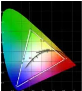
Color gradient triangle with a curved line inside, displayed on a grid background (no text or symbols)Figure 7-1. CIE chart
After enabling RealColor™ set the color temperature in the menu PICTURE > REALCOLOR > TEMPERATURE. Values between 3200K and 9300K can be selected. These color temperatures are tracking the "black body curve"- the black curved line in the center of CIE Chart in Figure 7-1. The default is the D65 illuminant at 6500K.
The white point can also be set to a custom value defined by an x, y coordinate not linked to the black body. Go to menu PICTURE > REALCOLOR > X-COORDINATE and PICTURE > REALCOLOR > Y-COORDINATE to change the white point.
7.2.1 Defining the system color gamut
All colors visible to the eye are defined by CIE Chart in Figure 7-1. The boundary of the colors the projector can display is called the system color gamut. The white triangle in the figure is an example of a system color gamut. By default the projector has the widest possible system gamut.
The system color gamut cannot be expanded outside native color gamut.
It may be desirable to change the system color gamut of the projector to:
• Color-match multiple projectors.
- Meet defined color standards, like REC 709.
- Create a special "look" to the image.
Before the system color gamut can be changed, the desired RealColor™ mode has to be defined. To change the RealColor™ mode please go the menu PICTURE > REALCOLOR > DESIRED VALUES > DESIRED COORDS MODE.
RealColor™ has to be enabled for the desired system gamut to be applied. Go to menu PICTURE > REALCOLOR > COLOR CORRECTION to enable RealColor™.
After RealColor ^™ is enabled and the desired color correction mode is selected, please go the menu entry PICTURE > REALCOLOR > DESIRED VALUES to change the color points to your desired system color gamut.
7.3 Gamma
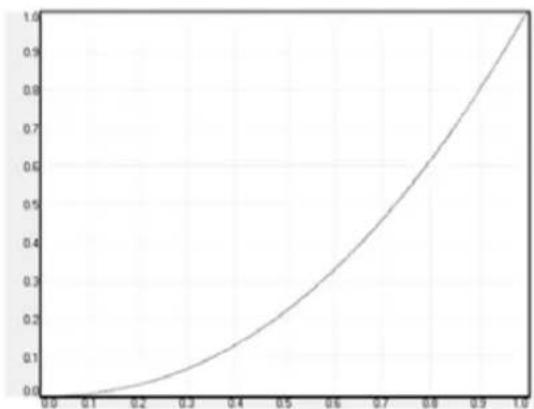
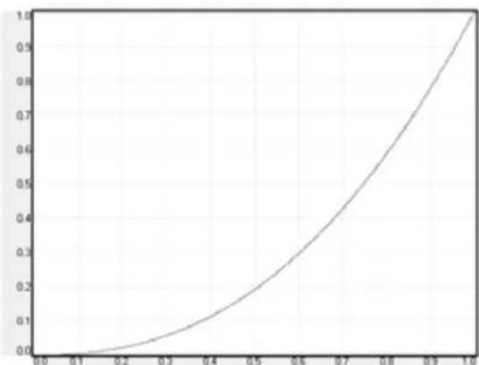
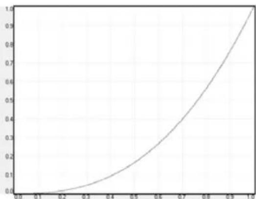
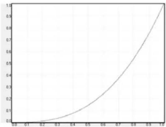
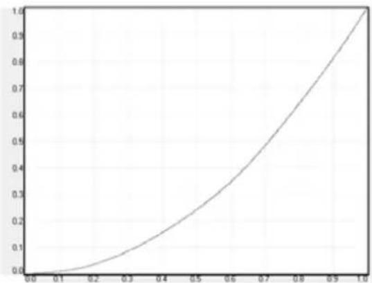
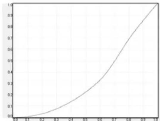
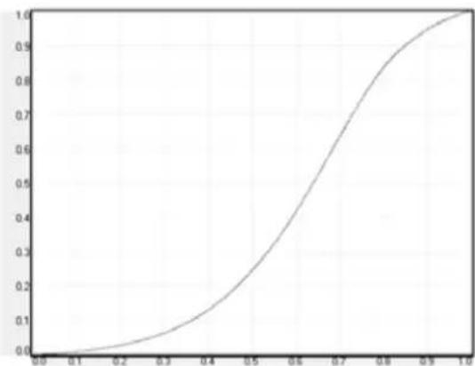
The projector features a set of 6 built in gamma curves: Film 2.2, Film 2.4, Film 2.6, Film 2.8, Video 1, Video 2, Computer 1, Computer 2, Dynamic and DICOM 180. The different gamma curves are displayed below.
The names of the curves are descriptive for their recommended use. Using any of the computer curves for video applications will results in significant image noise.
line
| x | y | | ---- | ---- | | 0.0 | 0.0 | | 0.1 | 0.05 | | 0.2 | 0.1 | | 0.3 | 0.15 | | 0.4 | 0.2 | | 0.5 | 0.25 | | 0.6 | 0.35 | | 0.7 | 0.5 | | 0.8 | 0.65 | | 0.9 | 0.85 | | 1.0 | 1.0 |Figure 7-1. Film 2.2 gamma
line
| x | y | | ---- | ----- | | 0.0 | 0.0 | | 0.1 | 0.0 | | 0.2 | 0.05 | | 0.3 | 0.1 | | 0.4 | 0.15 | | 0.5 | 0.2 | | 0.6 | 0.3 | | 0.7 | 0.45 | | 0.8 | 0.6 | | 0.9 | 0.8 | | 1.0 | 1.0 |Figure 7-2. Film 2.4 gamma
line
| x | y | | ---- | ---- | | 0.0 | 0.0 | | 0.1 | 0.05 | | 0.2 | 0.1 | | 0.3 | 0.15 | | 0.4 | 0.2 | | 0.5 | 0.25 | | 0.6 | 0.3 | | 0.7 | 0.4 | | 0.8 | 0.55 | | 0.9 | 0.75 | | 1.0 | 1.0 |Figure 7-3. Film 2.6 gamma
line
| x | y | | ---- | ----- | | 0.0 | 0.0 | | 0.1 | 0.0 | | 0.2 | 0.0 | | 0.3 | 0.05 | | 0.4 | 0.1 | | 0.5 | 0.2 | | 0.6 | 0.35 | | 0.7 | 0.5 | | 0.8 | 0.7 | | 0.9 | 0.9 | | 1.0 | 1.0 |Figure 7-4. Film 2.8 gamma
line
| x | y | | ---- | ----- | | 0.0 | 0.0 | | 0.1 | 0.05 | | 0.2 | 0.1 | | 0.3 | 0.15 | | 0.4 | 0.2 | | 0.5 | 0.25 | | 0.6 | 0.3 | | 0.7 | 0.4 | | 0.8 | 0.5 | | 0.9 | 0.6 | | 1.0 | 0.7 |Figure 7-5. Video 1 gamma
line
| x | y | | ---- | ---- | | 0.0 | 0.0 | | 0.1 | 0.05 | | 0.2 | 0.1 | | 0.3 | 0.15 | | 0.4 | 0.2 | | 0.5 | 0.3 | | 0.6 | 0.4 | | 0.7 | 0.55 | | 0.8 | 0.7 | | 0.9 | 0.85 | | 1.0 | 1.0 |Figure 7-6. Video 2 gamma
line
| x | y | | ---- | ----- | | 0.0 | 0.0 | | 0.1 | 0.05 | | 0.2 | 0.1 | | 0.3 | 0.2 | | 0.4 | 0.35 | | 0.5 | 0.5 | | 0.6 | 0.7 | | 0.7 | 0.85 | | 0.8 | 0.95 | | 0.9 | 0.98 | | 1.0 | 1.0 |Figure 7-7. Computer 1 gamma
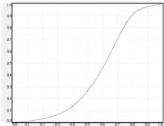
line
| x | y | | ---- | ----- | | 0.0 | 0.0 | | 0.1 | 0.05 | | 0.2 | 0.1 | | 0.3 | 0.2 | | 0.4 | 0.35 | | 0.5 | 0.5 | | 0.6 | 0.7 | | 0.7 | 0.85 | | 0.8 | 0.95 | | 0.9 | 0.98 | | 1.0 | 1.0 |Figure 7-8. Computer 2 gamma
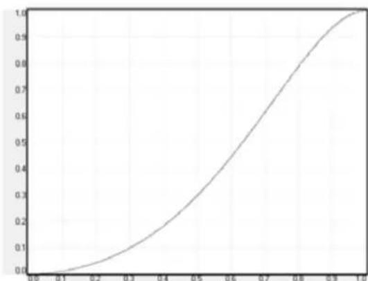
line
| x | y | | ---- | ----- | | 0.6 | 0.0 | | 0.7 | 0.2 | | 0.8 | 0.5 | | 0.9 | 0.8 | | 1.0 | 1.0 |Figure 7-9. Dynamic gamma
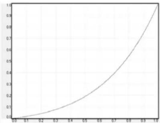
line
| x | y | | ---- | ---- | | 0.0 | 0.0 | | 0.1 | 0.05 | | 0.2 | 0.1 | | 0.3 | 0.15 | | 0.4 | 0.2 | | 0.5 | 0.25 | | 0.6 | 0.35 | | 0.7 | 0.5 | | 0.8 | 0.7 | | 0.9 | 0.9 | | 1.0 | 1.0 |Figure 7-10. DICOM 180 Lux* (example HB color wheel: other shapes with other alternatives) * Several DICOM settings (10, 60, 180, 250, 400 Lux - The higher Lux number (ambient light), the steeper the curve.
8 Technical specifications
Please see www.barco.com for more technical information.
9 Lamp change
The indicator on the keypad will turn RED when lamp life is expired. Change the lamp when lifetime expires. Always replace lamp with the same type and rating. USE ORIGINAL LAMPS ONLY.
The lamp holder employs an electronic lamp timer that is tracking the life time of the lamp. Always disconnect the power cord and wait until the projector has cooled down (60 minutes) before opening the lamp cover.

Be careful not to touch the protective glass when replacing the lamp, this may cause the protective glass to overheat and break while in use.

Be extremely careful when removing the lamp module. In the unlikely event that the bulb ruptures, small glass fragments may be generated. The lamp module is designed to contain these fragments, but use caution when removing the lamp module.
Remove the used lamp:
- Unscrew the lamp door screw
- Open the lamp door
- Unscrew the three screws that hold the lamp in place
- Pull the lamp out using the handle
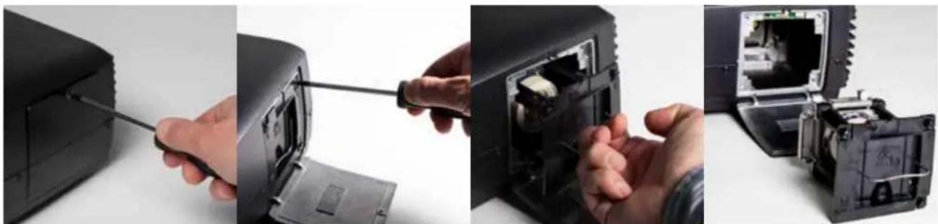
natural_image
Four-panel photo showing a hand inserting a screwdriver into a device, revealing internal components (no text or symbols visible)Replace with a new lamp in reverse order:
- Insert a new lamp. Observe the guide pins and make sure the lamp is fully inserted
- Fasten the three screws securely
- Close the lamp door
- Tighten the lamp door screw firmly

In the unlikely event of a lamp rapture, a limited amount of mercury vapour may be emitted into the room. To avoid inhaling this mercury vapour (which is toxic, and can be harmful for lungs and nervous system) the room should be thoroughly ventilated for a period of at least 30 minutes. There are no known health hazards from exposure to lamps that are intact and which are used within an enclosed fixture. No adverse effects are expected from occasional exposure to broken lamps. As a matter of good practise, avoid prolonged or frequent exposure to lamps unless there is adequate ventilation. The major hazard from broken lamps is the possibility of sustaining glass cuts.
PRODUCTION ADDRESS
Habornveien 53
Model certification name:
GP9

- CT series
- User Manual
- Contents
- Introduction 7
- Safety and compliance 9
- What is in the box? 13
- Installation 15
- Overview 25
- Functionality 49
- Optimising the image 55
- Technical specifications 63
- Lamp change 65
- Introduction
- Thank you
- Training
- Symbols used in this documentation
- Safety and compliance
- General safety considerations
- Information/Warning - Potential Mercury Vapour Health Issues
- FCC compliance
- CANADA
- Statement WEEE (Waste Electrical and Electronic Equipment)
- Disposal of batteries in the product
- Turkey RoHS compliance
- What is in the box?
- The following components are standard delivery:
- Additional accessories available for the projector:
- Installation
- System considerations
- Ventilation
- Ventilation accessories
- Ceiling and rig mounting
- Locking the projector
- Projector angle (tilt)
- Selecting a lens
- Inserting a lens
- Changing/removing a lens
- Lens range
- Lens lock
- Lens shift
- Lens planarity (Scheimpflug adjustment)
- This adjustment is rarely needed, do not apply it unless it is required.
- Zoom, focus and iris
- Making the connections
- Connecting video and data sources
- Connecting control interfaces
- Source format integrity – EDID
- Image sizes
- Overview
- Keypad and indicator
- Wireless remote control
- Connectors
- Signal connectors
- Control connectors
- Menu system
- Top menu
- 3D main menu
- 3D > Dual head setup sub menu
- Picture main menu
- profile:
- RealColor:
- Picture > RealColor sub menu
- BrilliantColor™:
- desired values:
- white
- temperature:
- RealColor calibration:
- Picture > Advanced sub menu
- Installation main menu
- Installation > EDID sub menu
- Installation > Synchronization sub menu
- Settings main menu
- Settings > Pin Code sub menu
- PIN code enable:
- change PIN code:
- Settings > Network sub menu
- Settings > Factory Reset sub menu
- Settings > Service sub menu
- Languages main menu
- Status main menu
- synchronisation
- Status > Source Information sub menu
- Status > Source Information > Advanced sub menu
- Status > Source Synchronisation sub menu
- Functionality
- Powering On and Off
- Manual power control
- DPMS - power down
- Image alignment
- Image orientation
- Language
- System status
- Lamp power
- Source selection, source scan
- On screen display (OSD) messages
- Disabling the STATUS indicator
- Setting the background color
- Setting OSD menu timeout
- Selecting the startup logo
- Picture by Picture (PbP)
- To view PbP:
- Standby ECO mode
- PIN code
- Disabling the wireless remote control (IR) receivers
- Software upgrades
- When upgrading the software the projector must always be in standby position!
- Optimising the image
- Calibration data
- Updating RealColor™ calibration data
- RealColor™ modes
- Setting a white point or color temperature
- Defining the system color gamut
- Gamma
- Technical specifications
- Lamp change
- Remove the used lamp:
- Replace with a new lamp in reverse order:
- PRODUCTION ADDRESS
Brand : Barco
Model : CTHD-61B
Category : Vidéo-projecteur