
Symphony I/O Mk II - Hi-Fi System Apogee - Free user manual and instructions
Find the device manual for free Symphony I/O Mk II Apogee in PDF.


| Product Type | Modular Multi-Channel Audio Interface / AD/DA Converter |
| Brand | Apogee |
| Model | Symphony I/O Mk II |
| Dimensions (Chassis) | 19 in. (48.26 cm) with rack ears x 11.5 in. (29.2 cm) x 3.5 in. (8.9 cm) |
| Weight (Chassis) | Approx. 15 lbs (6.8 kg) without modules |
| Power Supply | AC 90-240V, 50-60 Hz, 150W |
| AD Conversion | THD+N: -115 dB, Dynamic Range: 122 dB (A-weighted), Max Input: +24 dBu (ref +4 dBu) |
| DA Conversion | THD+N: -119 dB, Dynamic Range: 126 dB (A-weighted), Max Output: +24 dBu |
| Maximum Sample Rate | 192 kHz / 24-bit |
| Modular I/O Slots | 2 module card slots; up to 32 inputs and 32 outputs per chassis |
| Connectivity Options | Thunderbolt 2 (2 ports), Pro Tools HD, Waves SoundGrid, Word Clock I/O |
| Headphone Output | 1x 1/4" TRS, Constant Current Drive, THD+N: -110 dB, 121 dB dynamic range |
| Front Panel | Touchscreen display, control knob, headphone output, power button |
| Software Control | Symphony Control software (macOS 10.10+); includes Essentials and Primary windows |
| Standalone Mode | Operates without computer; sample rate & clock source adjustable from front panel |
| Talkback Feature | Uses Mac built-in mic, external mic, or digital input; auto-dims monitor outputs |
| Surround Support | Supports Dolby Atmos 7.1.4 or 11.1 surround output |
| Maintenance & Cleaning | No user-serviceable parts; clean exterior with dry cloth; avoid liquids |
| Safety Warnings | Power off speakers when powering unit on/off; do not interrupt firmware update; use proper grounding |
| Spare Parts & Repairability | Module cards (Mk II and compatible original) available; repair through Apogee or authorized centers |
| Warranty | 12 months limited warranty; registration required for updates |
Frequently Asked Questions - Symphony I/O Mk II Apogee
User questions about Symphony I/O Mk II Apogee
0 question about this device. Answer the ones you know or ask your own.
Ask a new question about this device
Download the instructions for your Hi-Fi System in PDF format for free! Find your manual Symphony I/O Mk II - Apogee and take your electronic device back in hand. On this page are published all the documents necessary for the use of your device. Symphony I/O Mk II by Apogee.
USER MANUAL Symphony I/O Mk II Apogee
Apogee Symphony I/O Mk II
User's Guide

April 2017
Contents
Overview 5 ......
Introduction......5
Features....5
Package Contents ....6
Register your product : apogeedigital.com/register ......6
Symphony I/O Mk II Panel Tour ....7
Front Panel 7
Rear Panel 7
Module Cards ....8
Mk II Cards ....8
8x8 Mk II Module 8
16x16 Mk II Module 9
Compatible Original Cards 9
Mic Pre Module....9
2x6 Analog + AES + 8 Optical Module ....10
8x8 Analog + 8 AES/Optical IO Module....11
16x16 Analog IO Module....12
Incompatible Original Cards ....12
Option Cards ....13
Thunderbolt Card....13
Pro Tools HD Option Card....13
Control - Hardware Remote 14
Thunderbolt-Equipped Model 15
Features....15
System Requirements....15
Setup....16
Download and Install Software....16
Making Connections....17
Single-Unit: 17
Multi-Unit: 17
Precautions when powering Symphony On/Off ....17
Update Symphony Firmware....18
Getting Started with Audio Software ....20
Select Symphony for Mac System Sound Output....20
Route Mac System Sound to Different Outputs 21
Select Symphony in your DAW....22
Select Symphony in Logic Pro X....22
Select Symphony in Pro Tools....22
Monitoring the Input Signal....23
Using your DAW to Monitor....23
Enable Input Monitor in Logic Pro X 23
Enable Input Monitor in Pro Tools....23
Navigating The Front Panel Touchscreen....24
Pro Tools HD Equipped Model....26
Changing to Pro Tools HD Audio Interface Mode:....26
Update Symphony Firmware - Pro Tools HD Option Card: 27
System Requirements: 27
Main Features....28
Thunderbolt Audio Interface Mode 28
Selecting the Thunderbolt Audio Interface Mode 28
Symphony Control 29
Essentials Window....30
Primary Window....31
Tool Bar 31
System Sidebar....32
Device Sidebar....32
I/O View....33
I/O Channel Section - INPUT 34
I/O Channel Section - OUTPUT....35
Mix View 36
Mixer Section....36
Monitor/Output Section 38
Remote Window 39
Hover Help Window 40
Menu Bar Menus....41
Symphony Control Menu 41
File Menu....41
View Menu....41
Window Menu....42
Help Menu 42
Monitor Control Center....43
Headphones 43
Monitor Outputs....43
How to set the Monitor Outputs for Stereo Speakers 43 ....
How to set the Monitor Outputs as a fixed Line-Out 43 ....
How to setup and use Multiple Speaker Sets ....44
How to connect and configure a Surround Speaker Setup 44 ....
Talkback 45
Selecting the Talkback Source....45
Choosing the Talkback Destination ....46
Standalone Functionality ....46
HOME Screen....46
SETTINGS Screen > Configuration tab....47
Configure Complex Standalone Routing using Symphony Control....48
Clocking with External Equipment 49
Configure Symphony as Clock Slave....50
Reference 51
Understanding Latency ....51
Soft Limit ....53
Pin Out Diagrams....54
Analog and Inserts....54
AES IN/OUT 55
Specifications....56
System Requirements....56
Factory Hardware Reset / Initialize ....56
Technical Details 57
General Details....57
Additional Support 58
General Support ....58
Apogee Pro Care ....58
Warranty Information and Legal Notices .....59
Overview
Introduction
Symphony I/O Mk II is a multi-channel audio interface featuring Apogee's newest flagship AD/DA conversion, modular I/O (up to 32 inputs and outputs per chassis), intuitive touchscreen display and optional world-class microphone preamps. Designed to deliver professional sound quality for audio recording, mixing and mastering, Symphony I/O is the ultimate music production centerpiece for any modern studio.

Features
- Best AD/DA conversion of any Thunderbolt™ audio interface
- Up to 32 channels of modular analog I/O with optional 8 mic preamps
- Best per-channel value of any interface in it's category
- Choice of Thunderbolt, Pro Tools® HD (Mac/PC) or Waves SoundGrid® connectivity*
• Ultra-low latency performance - Intuitive touchscreen display and front panel control
- Option card slot for future platform flexibility
- Designed in California, Built in the U.S.A.
Package Contents
• Symphony I/O Mk II
• 3 pin-IEC power cable
- QuickStart Guide
- Warranty Booklet
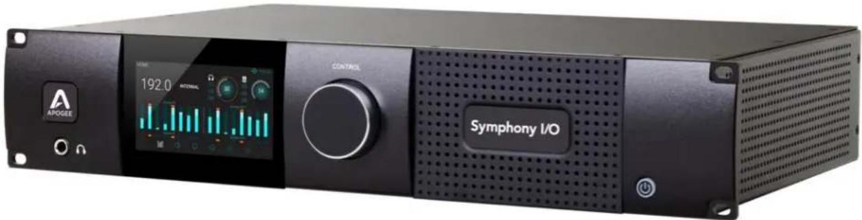

Register your product : apogeedigital.com/register
- Access Apogee's expert Technical Support for free
- Receive important product update information by email
• Take the Customer Satisfaction Survey for a chance to win Apocalypse gear!
Symphony I/O Mk II Panel Tour
Front Panel

- Headphone Output
a. 1/4" TRS connection provides an assignable stereo headphone output
-
Control Knob
-
Touchscreen
a. Symphony I/Os front panel touchscreen offers convenient access to every setting
b. Routing and the low latency Mixer can only be controlled in Symphony Control software
- Power Button
Rear Panel
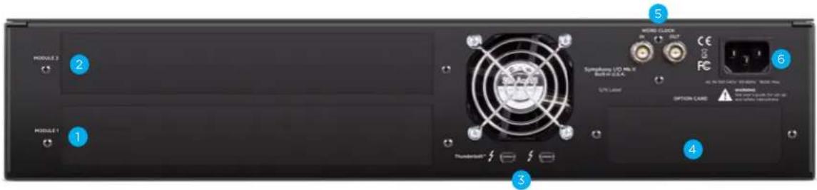
- Module Slot 1
- Module Slot 2
- Thunderbolt ports (Symphony Mk II Thunderbolt model only)
- Option Card Slot
- Word Clock I/O
- AC Power
Module Cards
The Symphony I/O Mk II has a configurable chassis allowing it the flexibility for use in any environment. Two card slots can be filled by any combination of several module cards providing a solution for everyone.
Mk II Cards
Mk II cards benefit from our most refined converter technology and engineering techniques which results in the lowest distortion and greatest dynamic range of any A/D converter we've ever designed, and a more powerful & robust D/A that maintains fidelity and punch.
8x8 Mk II Module

Provides a total of 16 channels of audio input and output:
- 8 channels of analog input and output
- 8 channels of digital input and 8 channels of digital output through either the AES DB25 connector (Yamaha Pin-out configuration), or Optical ports
To select either Optical or AES digital audio:
- Power off the Symphony I/O and disconnect the Thunderbolt cable.
- Toggle the DIG I/O button to the desired position
- Power the Symphony I/O on and reconnect the Thunderbolt cable.
Optical ports can be configured to use the S/PDIF or ADAT/SMUX protocols.
| S/PDIF | 44.1 - 192k Sample Rates | - 2 channels of audio in and 2 channels of audio out |
| ADAT | 44.1 - 48k Sample Rates | - 8 channels of audio in and 8 channels of audio out |
| SMUX | 88.2 - 96k Sample Rates | - 4 channels of audio in and 4 channels of audio provided per port |
| - 8 c h a n |
Digital Coaxial RCA S/PDIF ports are also provided.
- SPDIF IN replaces a pair of analog or digital audio inputs. Routing of the S/PDIF input is set with the S/PDIF Replaces drop down menu, found in the Symphony Control Software's Device Sidebar.
- SPDIF OUT will duplicate any pair of analog or digital audio outputs. Routing of the S/PDIF Output is set with the S/PDIF Mirrors drop down menu, found in the Symphony Control Software's Device Sidebar.
16x16 Mk II Module

Provides 16 channels of analog input and output.
Digital Coaxial RCA S/PDIF ports are also provided.
- SPDIF IN replaces a pair of analog or digital audio inputs. Routing of the S/PDIF input is set with the S/PDIF. Replaces drop down menu, found in the Symphony Control Software's Device Sidebar.
- SPDIF OUT will duplicate any pair of analog or digital audio outputs. Routing of the S/PDIF Output is set with the S/PDIF Mirrors drop down menu, found in the Symphony Control Software's Device Sidebar.
NOTE: The Mk II module cards cannot be used in the original Symphony I/O chassis.
Compatible Original Cards
Most cards from the original Symphony I/O can be used in the Symphony I/O Mk II chassis.
Mic Pre Module

The Mic Preamp Module upgrades the functionality of any 8x8 or 16x16 module by adding mic preamps to the existing line inputs. A direct connection between the Mic Preamp Module and the Analog I/O Module inserts a mic preamp stage before the line inputs.
- INSTRUMENTS 1-4 - These 1/4" TS connectors accept input from a wide range of instruments, including keyboards, guitars and other electronic instruments. The input impedance is high enough to avoid the loading of input sources such as passive electric guitars and basses.
- INSERTS Send 1-8 - This DB-25 connector provides 8 analog balanced line level sends routed after each channel's mic preamp stage.
- INSERTS Return 1-8 - This DB-25 connector accepts 8 analog balanced line level returns routed before each channel's A/D conversion stage.
Use the INSERT sends and returns to insert analog line level gear (such as compressors and equalizers) between a channel's mic preamp and A/D conversion stage.
Symphony I/O Mk II - User's Guide Page 9
2x6 Analog + AES + 8 Optical Module

Provides up to 12 channels of audio input, and up to 16 channels of audio output.
INPUTS
2-channels of analog input via balanced XLR connectors
2-channels of AES digital audio input via XLR female connector
Up to 8-channels of digital audio input via Optical connector
SPDIF 44.1 - 192k Sample Rates - 2 channels
ADAT 44.1 - 48k Sample Rates - 8 channels
SMUX 88.2 - 96k Sample Rates - 4 channels
OUTPUTS
6-channels of analog output via DB25 connector
2-channels of AES digital audio output via XLR make connector
Up to 8-channels of digital audio output via Optical connector
SPDIF 44.1 - 192k Sample Rates - 2 channels
ADAT 44.1 - 48k Sample Rates - 8 channels
SMUX 88.2 - 96k Sample Rates - 4 channels
The Optical format is selected in the Symphony Control Software's I/O View of the Primary Window.
Digital Coaxial RCA S/PDIF ports are also provided.
- SPDIF IN replaces a pair of analog or digital audio inputs. Routing of the S/PDIF input is set with the S/PDIF. Replaces drop down menu, found in the Symphony Control Software's Device Sidebar.
- SPDIF OUT will duplicate any pair of analog or digital audio outputs. Routing of the S/PDIF Output is set with the S/PDIF Mirrors drop down menu, found in the Symphony Control Software's Device Sidebar.
8x8 Analog + 8 AES/Optical IO Module

Provides a total of 16 channels of audio input and output:
- 8 channels of analog input and 8 channels of analog output
- 8 channels of digital input and 8 channels of digital output through either the AES DB25 connector (Yamaha Pin-out configuration), or Optical ports
To select either Optical or AES digital audio:
- Power off the Symphony I/O and disconnect the Thunderbolt cable.
- Toggle the DIG I/O button to the desired position
- Power the Symphony I/O on and reconnect the Thunderbolt cable.
Optical ports can be configured to use the S/PDIF or ADAT/SMUX protocols.
| S/PDIF | 44.1 - 192k Sample Rates | - 2 channels of audio in and 2 channels of audio out |
| ADAT | 44.1 - 48k Sample Rates | - 8 channels of audio in and 8 channels of audio out |
| SMUX | 88.2 - 96k Sample Rates | - 4 channels of audio in and 4 channels of audio provided per port |
| - 8 c h a n |
Digital Coaxial RCA S/PDIF ports are also provided.
- SPDIF IN replaces a pair of analog or digital audio inputs. Routing of the S/PDIF input is set with the S/PDIF Replaces drop down menu, found in the Symphony Control Software's Device Sidebar.
- SPDIF OUT will duplicate any pair of analog or digital audio outputs. Routing of the S/PDIF Output is set with the S/PDIF Mirrors drop down menu, found in the Symphony Control Software's Device Sidebar.
Note: The two variants of the 8x8 card are also compatible:
8x8 + AES only

8x8 + Optical only

16x16 Analog IO Module

Provides 16 channels of analog input and output.
Digital Coaxial RCA S/PDIF ports are also provided.
- SPDIF IN replaces a pair of analog or digital audio inputs. Routing of the S/PDIF input is set with the S/PDIF Replaces drop down menu, found in the Symphony Control Software's Device Sidebar.
- SPDIF OUT will duplicate any pair of analog or digital audio outputs. Routing of the S/PDIF Output is set with the S/PDIF Mirrors drop down menu, found in the Symphony Control Software's Device Sidebar.
Incompatible Original Cards
The following cards cannot be installed into a Symphony I/O Mk II chassis:
16 Analog In + 16 Digital Out (A16 IP)

16 Analog Out + 16 Digital In (A16 OP)

Option Cards
The Symphony I/O Mk II has one Thunderbolt Card slot & one Option Card slot. A Symphony I/O Mk II can be configured with just the Thunderbolt Card, just an Option Card, or both.
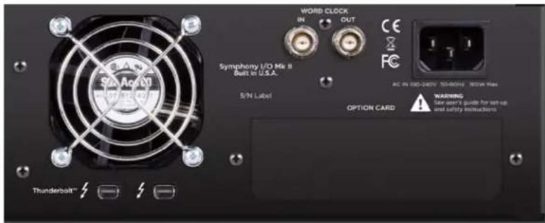
Thunderbolt Card
The Thunderbolt Card enables connectivity to a Thunderbolt-equipped Mac. This card is required for the unit to operate with the Symphony Control Software as well as with the optional Control hardware remote.
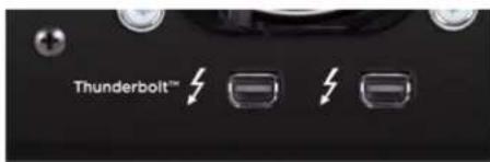
Two Thunderbolt2 ports are provided. They can be used for connecting to a second Symphony IOMKII or to attach additional Thunderbolt peripherals such as a hard drive or external display to your Mac system.
Pro Tools HD Option Card
The Pro Tools HD Option card enables connectivity to Pro Tools HD Systems such as HDX and HD Native cards. For extensive Refer to the for details on operation when equipped with this option card.

Primary Port - Mini PC32 port (also called Mini Digilink) used to connect to compatible Pro Tools HD card.
Aux - USB port used for firmware updates
Loop In / Out - For Syncing with other Pro Tools HD interfaces
Control - Hardware Remote
This programmable control surface is used to adjust settings and parameters of your Symphony I/O Mk II Thunderbolt. For a full list of programmable features, see the Control Remote Assignments section of the Symphony Control Software section on page 39.
To Computer - Micro USB port for connecting to your computer.
U s e a s
Display Indicators - Shows currently selected input, the input type, as well as the output selection.
Assignable Buttons - Performs the assigned function. Any function can be assigned to any button via the Symphony Control software (pg 39)
The factory default assignments are:
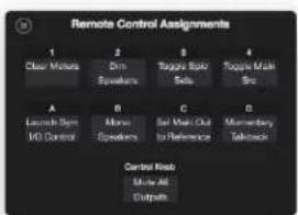
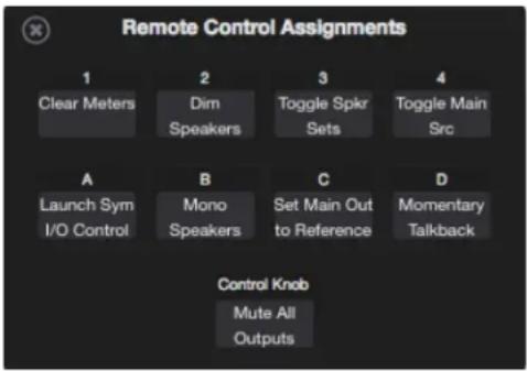
1 - Clear Meters A - Launch Symphony I/O Control
2 - Dim Speakers B - Mono Speakers
3 - Toggle Spkr Sets C - Set Main Out to Reference
4 - Toggle Main Source D - Momentary Talkback
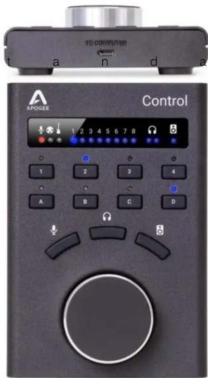
Microphone button
- One push focuses the knob on adjusting the input gain level
- Multiple presses cycles through the input channels
Headphone button
- One push focuses the knob on adjusting the headphones volume level
- Multiple presses cycles through the headphone outputs
Speaker button
- Focuses the knob on adjusting the speaker volume level
Control Knob
- Turn to adjust settings
- Push down to mute all outputs
- The push button can be assigned to another function via the Symphony Control software (pg 39)
Thunderbolt-Equipped Model
Features
• All new Symphony Control software
• Support of two Symphony I/O Mk II Thunderbolt chassis for up to 64 Inputs and Outputs
• Save & recall snapshots lets you save your sessions settings
- FX Send lets you use your DAW's best reverb with Symphony Control low latency mixers
• Support for Apogee Control Hardware Remote
- Innovative Talkback feature allows use of the Mac's Built in Mic, External Mic, or Digital Input.
- Standalone Mode offers use of Symphony I/O Mk II without a computer connected - Sample Rate and Clock Source are now adjustable from the front panel.
• Support for Dolby Atmos 7.1.4 or 11.1 Surround Output
System Requirements
• macOS 10.10.5 Yosemite or greater
• Mac with Thunderbolt
• Thunderbolt 3 compatible with Apple USB-C to Thunderbolt Adapters.
• 4GB minimum RAM, 8GB recommended
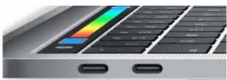
Some older Macs have mini DisplayPort connections that, while identical in appearance to a Thunderbolt port, don't support Thunderbolt peripherals. Verify that the Thunderbolt logo is present on your Mac's ports.
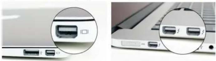
natural_image
Close-up of a laptop's rear panel showing two USB port thumbnails (no text or symbols visible)X Mini DisplayPort
√ Thunderbolt Port
For Macs equipped with a Thunderbolt-3 USB-C port, Apple's Thunderbolt 3 to Thunderbolt 2 adapter can be used.
natural_image
Close-up of a laptop keyboard with two USB ports and a colorful stripe on the left (no text or symbols visible)
Thunderbolt-3 Port
Thunderbolt-3 to Thunderbolt-2 adapter
Setup
Download and Install Software
Before Symphony I/O Mk II Thunderbolt will be recognized by your Mac, you must download & install the latest Symphony I/O Mk II Software from Apogee's website:
www.apogeedigital.com/support/symphony-io-mk-ii
The download comes in the form of a .dmg image file. Open it to view the contents.
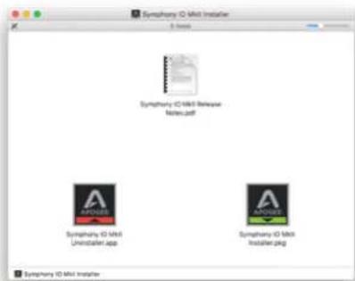
Inside you will find these items:
• Symphony IO MkII Control 1.0 Release Notes.pdf
• Symphony IO MkII Installer.pkg
• Symphony IO MkII Uninstaller.app
Double-click to launch the Symphony I/O Mk II Installer.pkg
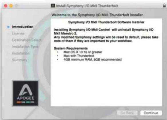
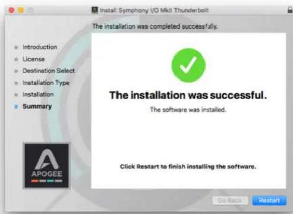
A dialog box will appear with a series of steps Follow the prompts to complete the installation
Once complete you will be required to restart your computer
As a result of the software install:
- Apogee Symphony I/O MkII Control app is placed in the Mac's Applications folder
- When connected, Symphony Thunderbolt appears as a device in Mac Sound System Preferences & AMS Utility
- Symphony IO MkII Firmware Updater.app is placed in the Mac's Utilities folder
Making Connections
Single-Unit:
- Connect a Thunderbolt cable from the Mac to either of the Symphony I/O Mk II's ports.
Multi-Unit:
Two Symphony VOMK II Thunderbolt units can be connected to the same system for up to 64 channels of input and output:
- Connect one Thunderbolt cable from the Mac to either port of the unit intended to be the Master Unit A.
- Using a second Thunderbolt cable, connect from the remaining Thunderbolt port on Master Unit A, to either of the second unit's Thunderbolt port.
A Word Clock connection must also be made between the two units:
- Using BNC Word Clock cable, connect from the Master unit's WC OUT port to the second unit's WC IN port.
Precautions when powering Symphony On/Off
Before powering on, ensure that any speakers or amplifiers connected to Symphony's analog outputs are powered off, or the volume turned down to the minimum setting. This will prevent audible "pops" that may occur as the unit boots up.
- Power off speakers and disconnect headphones
- Power Symphony On
- Power on speakers and connect headphones
Likewise, before powering Symphony off, ensure any speakers or amplifiers connected to Symphony's analog outputs are powered off, or the volume turned down to the minimum setting.
- Power off speakers and disconnect headphones
- Power Symphony Off
Update Symphony Firmware
The first time Symphony is used after the software installation, you will likely need to update the firmware.
Warning: Do not disconnect power or interrupt the firmware update process before it is complete as this may damage the unit

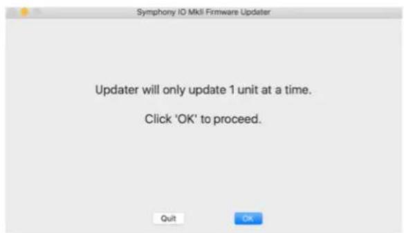
- Open the Symphony Firmware Updater.app which is located in the Mac's Applications > Utilities folder.

- Select your configuration and follow any prompts that may appear.
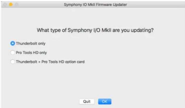
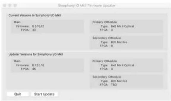
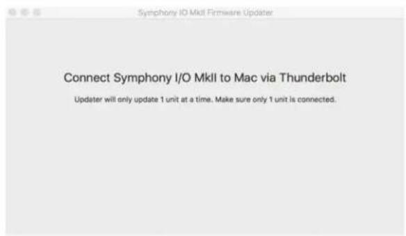
NOTE: If updating multiple units, they must be updated one at a time.
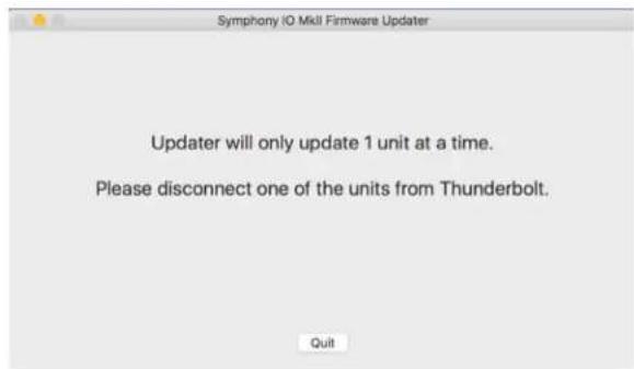
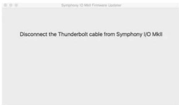
Disconnect the 2nd unit if it is connected to the first unit in the chain.
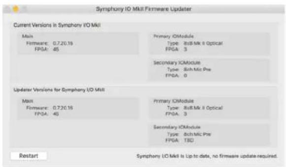
- Click Restart to reboot your computer and complete the Firmware Update process.
- Repeat for the second Symphony I/O Mk II if necessary
Getting Started with Audio Software
Select Symphony for Mac System Sound Output
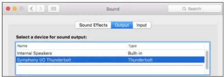
To route audio from general audio applications such as iTunes and Safari through Symphony I/O, it must be selected as the output device in Mac System Preferences.
Make sure you have already installed the most recent Symphony I/O Mk II Software from the Apogee website before proceeding.
-
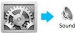
Click the 📄 icon in the upper-left corner of your Mac's display.
-
From the drop-down menu, select "System Preferences..."
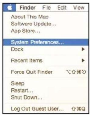
- In the System Preferences control panel, select "Sound"
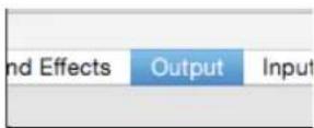
- At the top of the Sound Preferences panel, select the "Output" tab
- Under "Select a device for sound output:" click Symphony I/O Thunderbolt
Route Mac System Sound to Different Outputs
- Open the Audio/MIDI Setup Utility, found in the Applications > Utilities folder of your Mac
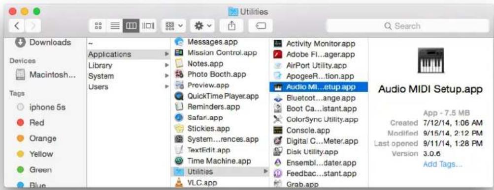
- In the Audio Devices window, [Control+click] on Apogee Symphony Thunderbolt.
- In the Menu that appears, select "Configure Speakers".
- If playing a stereo audio file, select the Stereo tab. If playing a multi-channel audio file, select the Multichannel tab.
- Select the desired Symphony output channel for each speaker assignment. For example, if you want iTunes to play out of Symphony channels 3 & 4, set Left Front to "3" and Right Front to "4".
- Select the Apply button.
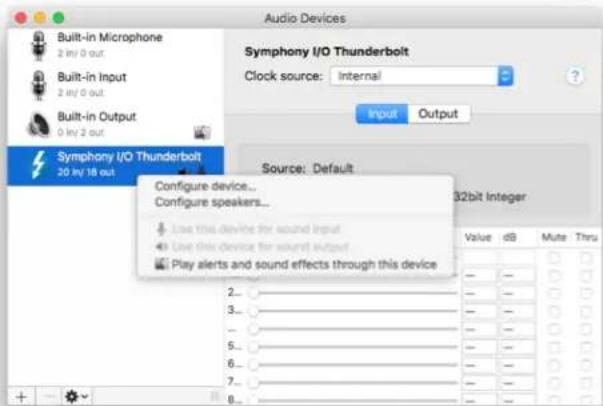
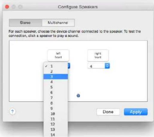
Select Symphony in your DAW
Most professional applications have their own audio preferences that are separate from the Mac System Preferences. Basic steps for setting up Symphony are provided. For more detail on this topic, refer to the documentation that comes with your recording program.
Select Symphony in Logic Pro X
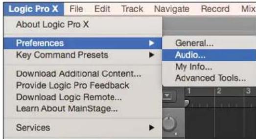
- Go to Logic Pro X > Preferences > Audio.
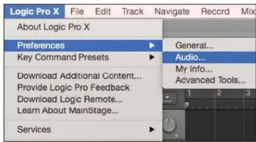
- In the Devices Tab, select Symphony I/O Thunderbolt in the Output and Input Device drop-down boxes.
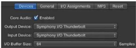
-
Start by setting the I/O Buffer Size to "64 Samples". This setting may need to be adjusted based on your computer's performance.
-
Select "Apply Changes" and close the Preferences window.

Select Symphony in Pro Tools
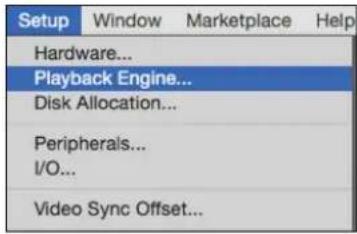
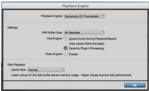
- Go to Setup > Playback Engine.
- In the Playback Engine drop-down box, select "Symphony Thunderbolt".

-
Start by setting the H/W Buffer Size to "64 Samples". This setting may need to be adjusted based on your computer's performance.
-
Select OK.
Monitoring the Input Signal
Using your DAW to Monitor
By default, Symphony is configured for your recording software or DAW to perform the monitoring duty of passing your input signal on to your output.
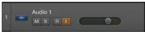
Enable Input Monitor in Logic Pro X
- Open Logic Pro X > Preferences > Audio
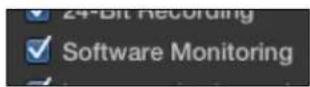
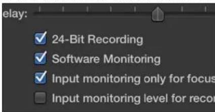
- Make sure the box next to "Software Monitoring" is checked.
- Select the "I" button in each track you'd like to input monitor.
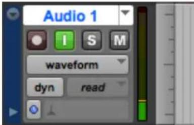
Enable Input Monitor in Pro Tools
- In Pro Tools Native, the "I" button enables input monitoring.
- Also make sure the Software Monitoring is checked in the Preferences > Audio > Devices menu.
Navigating The Front Panel Touchscreen
Most Symphony I/O settings can be controlled from the front panel. For full control over all settings, use the Symphony Control software.
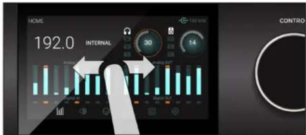
Swipe to navigate
You can swipe the screen left or right to access any of the main sections; HOME, MONITOR, INPUT, OUTPUT, DIGITAL I/O, SETTINGS. Swiping can be disabled in SETTINGS.
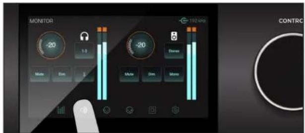
Tap section icons to navigate
You can also directly select any of the section icons on the bottom of the screen to jump directly to a section.
Symphony I/O Mk II's front panel touchscreen offers convenient access to nearly every setting.
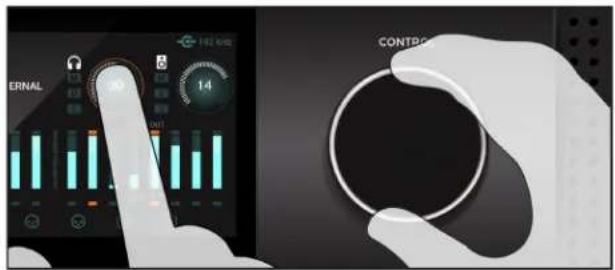
Control knob focus selection
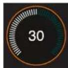
Settings that may be controlled using the front panel control knob are displayed as a circle; i.e. Speaker and Headphone, Input calibration and Gain levels
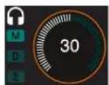
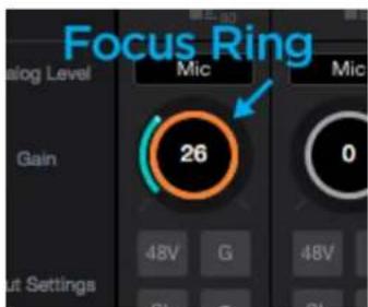
To "focus" the control knob to the desired setting, tap the circle; an orange ring indicates that the control knob is currently focused on the setting.
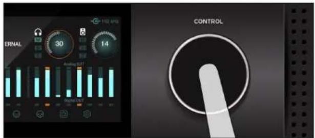
Muting with the control knob
Pressing the control knob mutes and un-mutes the sound coming out of Symphony I/O Mk II, and is indicated on the Home screen with the "M" lit up.
Touchscreen Section Overview
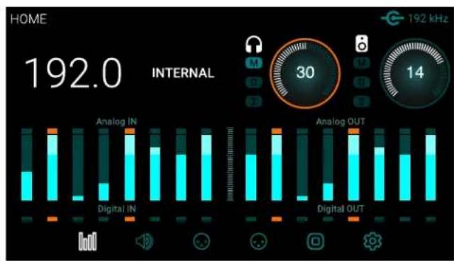
bar
| Category | Analog IN | Analog OUT | |---|---|---| | Home | 192.0 | 192 kHz | | Internal | 30 | 14 | The chart displays stacked bars representing the total values for each category (e.g., Analog IN in Group 1, Analog OUT in Group 2). The top label indicates "HOME" at 192.0.
HOME
Sample Rate, Clock Source, Headphone & Speaker output levels, Meters for all I/O, and section navigation
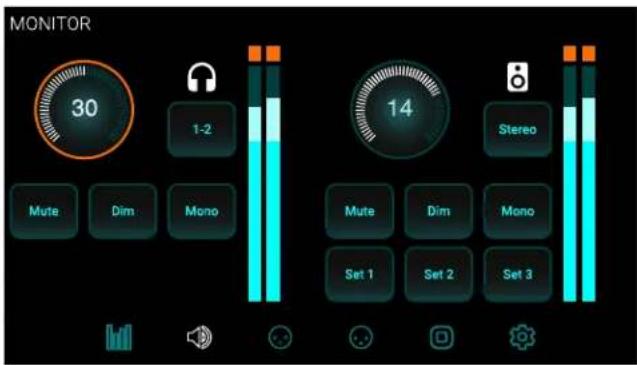

MONITOR
Headphone & speaker output levels, mute, dim, sum to mono, headphone output selection, speaker set selection and section navigation
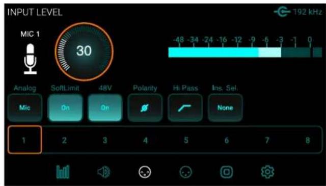

INPUT LEVEL
Analog input reference levels, calibration, Soft Limit, mic pre parameters (when 8 channel mic preamp module is installed)
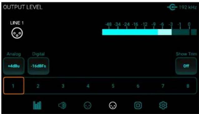

OUTPUT LEVEL
Analog output reference levels, calibration and section navigation
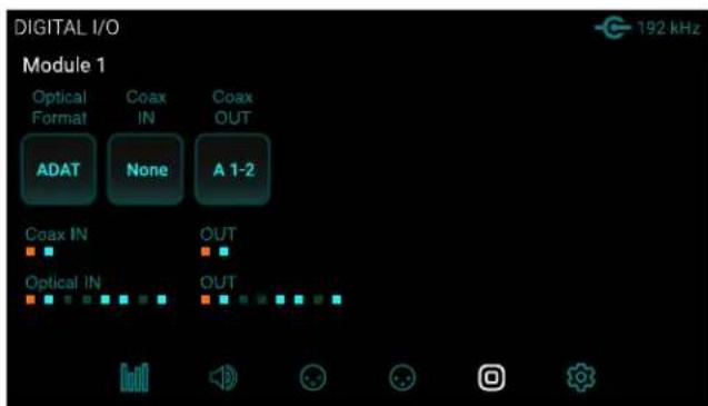

DIGITAL I/O
Digital format settings, Digital input signal meters, SPDIF Coax In replaces and coax output mirrors settings and section navigation
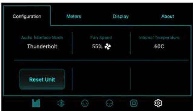

SETTINGS
Reset, WC termination, Internal temperature, Meter characteristics, Display brightness
Pro Tools HD Equipped Model
This Guide provides limited information about the operation of The Symphony I/O Mk II when equipped with the Pro ToolsHD Option Card.
REFER TO THE SYMPHONY I/O MK II HD ADDENDUM FOR COMPREHENSIVE INFORMATION ON OPERATION OF THE SYMPHONY I/O MK II WHEN EQUIPPED WITH THE HD OPTION CARD.
http://www.apogeedigital.com/support/symphony-io-mk-ii#tab-id-2
Changing to Pro Tools HD Audio Interface Mode:
If equipped with only the Pro Tools HD Option Card, the unit will automatically be in the correct interface mode. If equipped with both the Thunderbolt Card and a Pro Tools HD Option Card, the Symphony I/O Mk II must be switched to the Pro Tools HD Audio Interface mode:
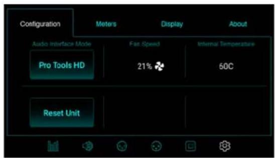
- Using the front panel Touch Display, scroll to the Settings > Configuration screen
- If the Audio Interface Mode is not "Pro Tools HD", touch the Audio Interface Mode button.
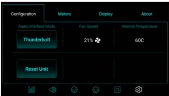
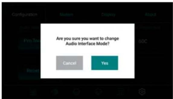
- Confirm that you want to switch modes by selecting "Yes".
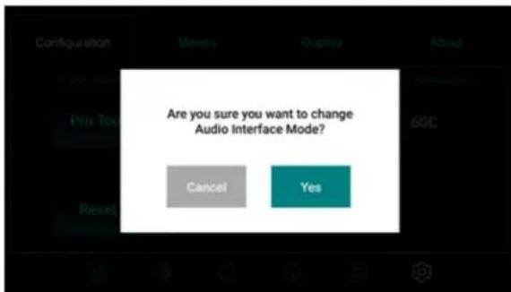
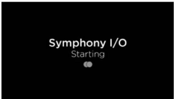
- The unit will reboot into the selected Mode.
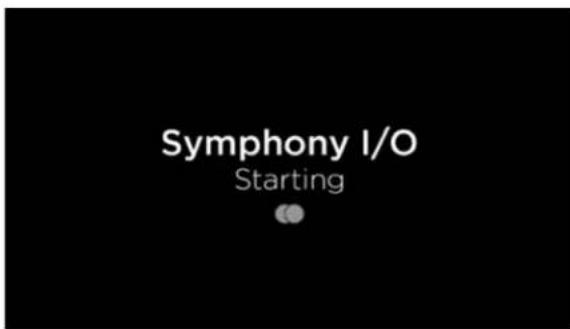
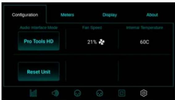
- The unit will reboot into the Pro Tools HD Audio Interface Mode
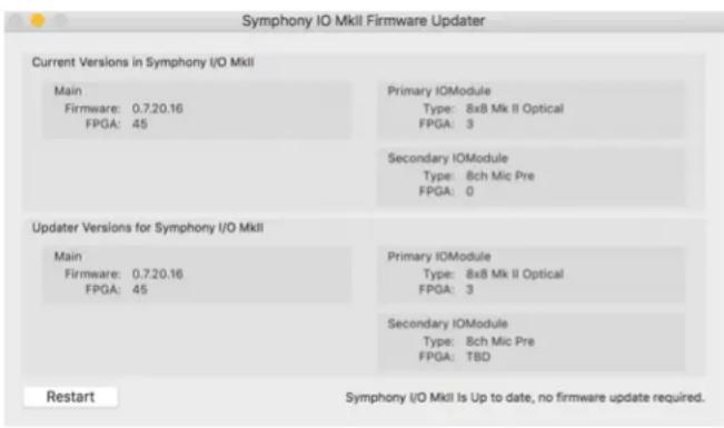
Update Symphony Firmware - Pro Tools HD Option Card:
The Symphony I/O Mk II with Pro Tools HD Option Card does not need any Apogee software installed in order to operate with your Pro Tools HD card. However there are occasional firmware updates that improves the performance of the Pro Tools HD Audio Interface Mode. Here's how to install Firmware Updates onto a unit with just the Pro Tools HD Option Card, or a unit with both Option Card and Thunderbolt Card installed:
System Requirements:
The Firmware update can only be performed on a Mac Computer
- macOS 10.10 or greater
-
USB 1, USB 2, USB 3, or USB-C port (a USB-C to USB adapter is required)
-
Download and install the latest software from www.apogeedigital.com/support as described on page 16
- Power On the Symphony I/O Mk II and ensure it is in the Pro Tools HD Audio Interface Mode (page 26)
- Connect a USB cable from the Option Card's AUX port to the computer
- Open Symphony IO MkII Firmware Updater.app
- Select your configuration and follow any prompts that may appear
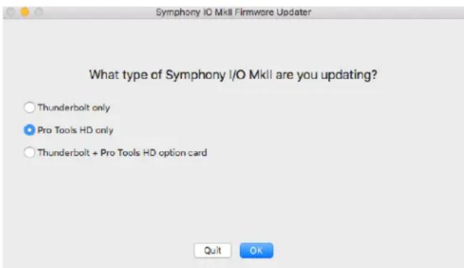
- Click Restart to reboot your computer and complete the Firmware Update process
Main Features
Thunderbolt Audio Interface Mode
The Thunderbolt Card provides a high-quality professional & low-latency connection to the Mac. Up to two Symphony I/O Mk II Chassis can be connected to the same system for up to 64 channels of inputs & 64 channels of outputs.
Before proceeding, please ensure the Symphony I/O Mk II Software has been installed, and firmware updated as described on page 16.
Selecting the Thunderbolt Audio Interface Mode
For units equipped with both the Thunderbolt Card, and an Option Card, ensure the unit is in the Thunderbolt Audio Interface Mode:
-
Using the front panel Touch Screen, navigate to the Settings > Configuration page.
-
If the Audio Interface Mode is not "Thunderbolt", touch the Audio Interface Mode button.
- Confirm that you want to switch modes by selecting "Yes".
- The unit will reboot into the selected Mode.
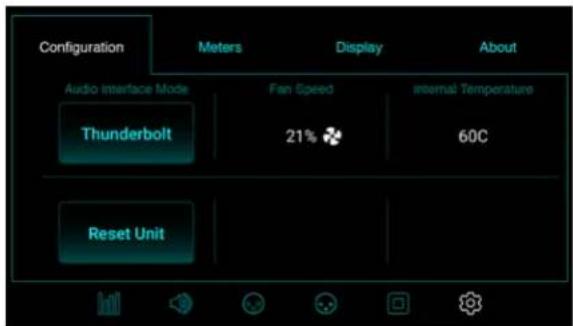
- You must unplug the Thunderbolt cable, then reconnect before the unit will be recognized by your Mac.
Symphony Control
Control of your Apogee Symphony I/O Mk II Thunderbolt is available through the Symphony Control software which is located in your Mac's Applications folder.

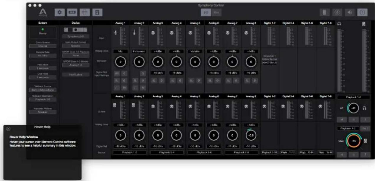
Symphony Control consists of four windows:
- Essentials
- Primary
- Hover Help
- Remote
Essentials Window
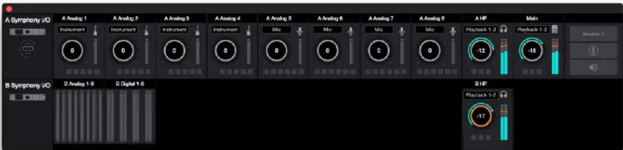
This window provides simple and compact controls for Input Channels and Monitoring. It's orientation can be changed between vertical and horizontal so that it can be placed to the side or end of your recording software.

- Orientation Button - Switches the Essentials window between horizontal and vertical view
- Analog Input Channels - Provides settings for the analog inputs.

- If equipped with the 8 mic pre module card, the Essential Window will show Mic and Instrument preamp settings as well as +4dBu and -10dBV Line Level options.
- The buttons at the bottom correspond to the Input Channel Settings: Phantom Power (48V), Soft Limit (SL), Group (G), Invert Polarity (ø), Hi-Pass ( ), and Insert (IN).
- Outputs - Headphones and speaker outputs settings are provided.
- Main Source Toggle Button - Toggle between two different Main Source settings.
- Talkback - Engages talkback to communicate with artists wearing headphones. Set the Talkback source and destination in the System Sidebar.
- Mute All - Mutes Headphones and Speakers outputs. Set the Talkback sure and destination in the System Sidebar.
When two chassis are connected together, Inputs and Outputs for both are displayed:
Primary Window
All features and settings of the Symphony I/O Mk II Thunderbolt can be controlled from the Primary window. It is broken down into several sections:
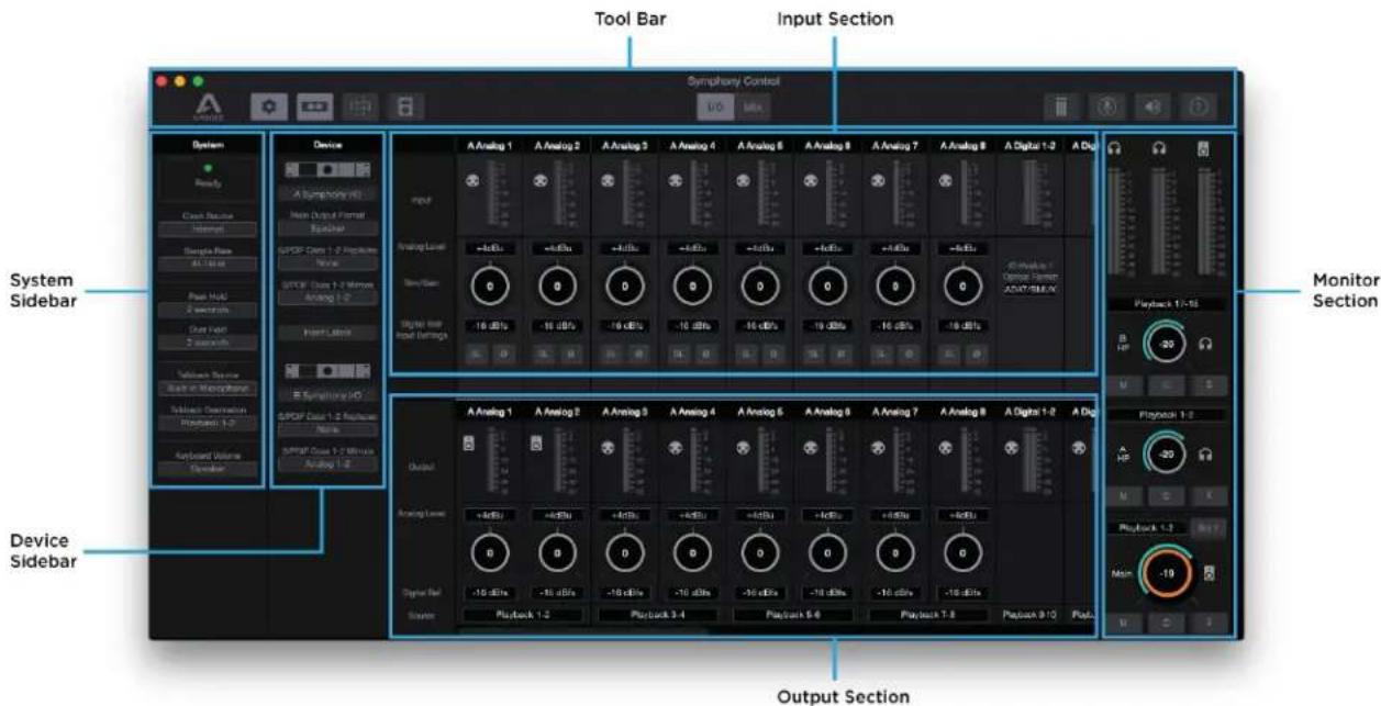
Tool Bar
The Tool Bar is always visible at the top of the Primary window. It provides the ability to show/hide the System Sidebar, Device Sidebar, Essentials window, Remote window and Hover-Help window. It also has buttons for Clear Meters, Talkback and Mute All outputs. Use it to switch between the I/O and Mix View.

- System Sidebar Button
- Device Sidebar Button
- Essentials Window Button
-
Remote Control Assignments Button
-
I/O View Button
-
Mix View Button
-
Clear Meters Button
- Talkback Button
- Mute All Button
- Hover Help Button
System Sidebar
Provides system wide settings that apply to your recording system as a whole.

-
System Status Display - This displays the status of the connected hardware.
-
Green - System is ready: Hardware is connected and recognized, and the digital clock is locked to the Clock Source.
-
Red - System not ready. Either the hardware is not connected, or the system is not locked to the Clock Source.
-
Clock Source - Selects the system clock source.
- Sample Rate - Sets the Symphony System's Sample Rate. In some cases this setting may be overridden by software running on the computer (i.e. When a DAW session project is opened).
- Peak Hold - Sets the time that peak indications are held on the level meters.
- Over Hold - Sets the time that over indicators are held on the level meters.
- Talkback Source - Select the source of the Talkback Signal. If your Mac is equipped with a Built-in Mic, select Built-in Mic as the source.
- Talkback Destination - Set the Playback channel destination for the Talkback signal. When using the low latency mixer, note that the Talkback signal is routed through the selected Playback mixer channel.
- Keyboard Volume - The audio system may be configured so that the Mac keyboard volume controls set the output level of Main speaker or headphone outputs.
Device Sidebar
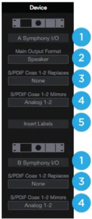
The Device Sidebar provides settings that are specific to the Symphony I/O Mk II hardware connected to the Mac.
- Device ID - Click to flash the Front Panel Status LED light for 3 seconds, to identify the hardware device to which Device settings apply. Also useful to verify a proper Thunderbolt connection.
- Main Output Format - Choose Speaker when connecting to powered speakers; choose Line when connecting to a mixer or other device with a volume control.
- S/PDIF Coax 1-2 Replaces - Select the pair of analog or digital hardware inputs to be replaced by the S/PDIF Coax input. Set to None if the Coax input is not in use.
- S/PDIF Coax 1-2 Mirrors - Select the pair of analog or digital hardware outputs to be mirrored (duplicated) but he S/PDIF Coax output.
- Insert Labels - Label the Insert points for when the 8 Mic Pre module card is installed.
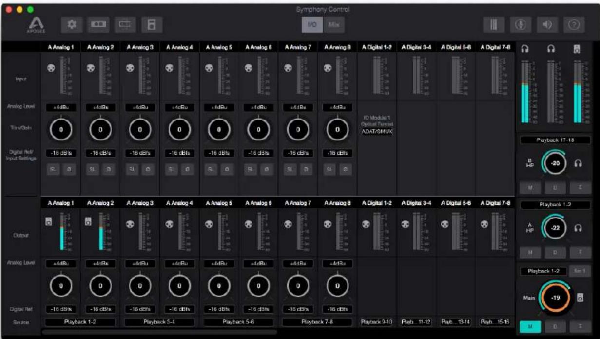
I/O View
The I/O view of the Primary window is separated into an INPUT channel section, and an OUTPUT channel section:
Apple Keyboard Navigation Tips
Use the Arrow keys to change Analog input and output settings;
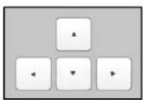
Press ◀▶ to scroll the orange focus ring through analog inputs and outputs.
Press ▲▼ to raise or lower the level highlighted with the focus ring.
Use the volume keys (F10, F11 and F12) to set the level of the Speaker or Headphone output.
I/O Channel Section - INPUT
This portion of the Primary Window displays Channels for Analog input, Digital input, and Playback from audio software.
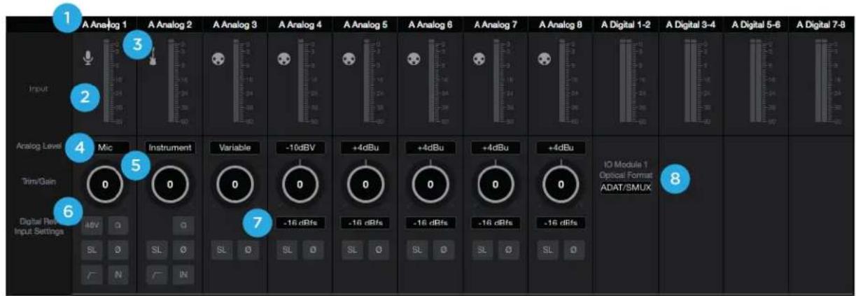
- Hardware Input Label - Indicates the analog or digital hardware input. Can be renamed by clicking the label and typing a user-customized label. If you've customized the labels and want to return to the default text, simply delete the text and press Return.
*These labels are transmitted to your DAW
- Hardware Input Level Meter - Shows the post-gain digital signal level coming into the channel.
- Input Icon - Shows the input type selected from the Analog Level drop-down
-
Analog Level Type Selector - Set the Analog input type for each channel. Command-click to set all channels simultaneously
-
Choose +4dBu when connecting to professional line level equipment such as an external mic pre, compressor, or EQ that has outputs at the +4dBu nominal level.
- Choose -10dBV when connecting to "semi-pro", hi-fi, or musical instrument gear with outputs at a -10 dBV nominal level.
* When the 8MP (mic pre) module is installed, additional entries for Microphone and Instrument appear:
- Choose Mic when connecting microphones or direct boxes, or any devices that needs to run through a microphone preamplifier. -XLR Input only
-
Choose Instrument when connecting a guitar or keyboard, or any high impedance (Hi-Z) instrument to the 1/4" input (balanced TRS or unbalanced TS). The signal is sent through a Hi-Z to Low-Z conversion circuit before sent through the microphone preamplifier circuit.
-
Input Trim / Gain Control -
-
When Analog Level is set to +4dBu/-10dBV, trim the analog input stage for precise calibration.
- When the 8MP (mic pre) IO Module is installed, set Microphone or Instrument input gain.
* Option + Click to reset to 0. Command + Click to reset all channels to 0.
- Input Settings - Provides options for the various inputs:

Soft Limit: This option begins to attenuate transient peaks at a threshold of -4dBfs.

Polarity Invert: Use this button to invert the polarity of the input signal
*When the 8MP (mic pre) module is installed, the following input settings become available:

Phantom Power: Use this button to enable 48 volt phantom power on the corresponding Analog In channel.
Condenser microphones require 48 volt phantom power to operate

- Group: The input gain controls of adjacent odd-even channels are adjusted simultaneously. Any level offsets that exists before inputs are grouped will be preserved after a group is chosen.

• High-Pass Filter: Use this button to engage an 80Hz, 12dB/octave high-pass filter on the input

- Insert: When engaged, the signal to the Insert Return DB25 port is routed to the A/D conversion circuit.
* NOTE that the Insert Send is always active and thus may be used as an analog direct out.
- Digital Reference - Sets the resulting digital level when an analog signal at the specified level (+4dBu or -10dBV) is connected. Most Apogee devices default is -16dBfs. Command-click to set all channels simultaneously.
* Note: It's best to set the Digital Input Reference level at the same settings as the Digital Input Reference level, to preserve unity gain through the system.
- Optical Format - Set the Optical Input ports to be either ADAT/SMUX or S/PDIF Optical.
- SPDIF: The two-channel SPDIF audio format is capable of utilizing a maximum sample rate of 96kHz.
- ADAT/SMUX : The multi-channel ADAT or SMUX format is capable of 8 channels of digital I/O at sample rates 44.1kHz - 48kHz, and 4 channels of digital I/O at sample rates 88.2kHz - 96kHz.
I/O Channel Section - OUTPUT
This portion of the Primary Window displays Channels for Analog Output, Digital output, and the Source of the output signal.
- Hardware Output Label - Indicates the analog or digital hardware output
- Output Channel Level Meter - Shows the digital signal level before the D/A conversion
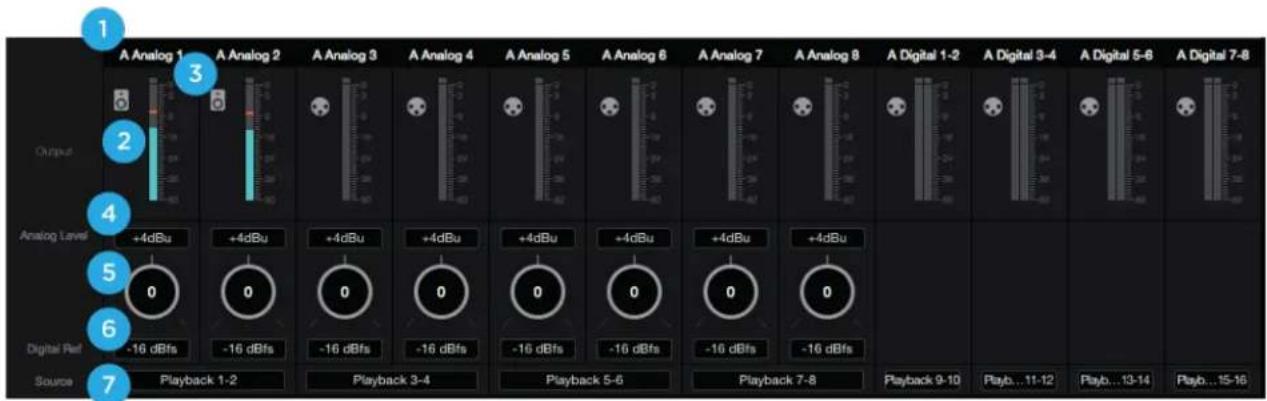
- Output Icon - Indicates which outputs volume level is controlled by the Main Output volume control, and which are fixed-volume line-level outputs.
-
Analog Level - Set the Analog output level for each channel. Match this level with the analog gear to which Symphony I/O Mk II is connected.
-
Choose +4dBu when connecting to professional line level equipment
-
Choose -10dBV when connecting to "semi-pro", hi-fi, or consumer equipment
-
Output Trim Control - Use to adjust the analog output stage for precise calibration.
Option+click to reset to 0. Command+click to reset all channels to 0.
- Output Digital Reference - Set the output digital reference level. In most cases, the output digital reference level should be set to the same as the input digital reference level. Most Apogee devices default is -16dBFS.
Symphony I/O Mk II - User's Guide Page 35
Command+click to set all channels simultaneously.
-
Hardware Output Source - Set the signal source for the pair of hardware analog our digital outputs.
-
Choose a Playback source to route audio directly from your DAW
- Choose a Mixer source to route audio from a Symphony Control mixer
- Choose a Hardware Input source to route audio directly from an I/O Module input
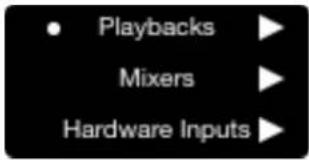
Mix View
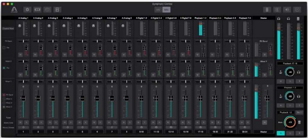
The Mix View of the Primary window is where access and control of the low-latency mixers are found:
Mixer Section
The mixer section provides several Direct Monitor mixers, and a special FX Send mixer for workflows that utilize the low-latency Direct Monitoring features of your Symphony I/O Mk II Thunderbolt interface.
-
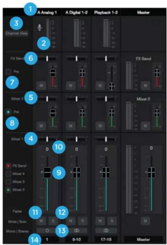
Channel Top Label - Indicates the Mixer Channel's Source. Can be renamed by clicking the label and typing a user-customized label. If you've customized the labels and want to return to the default text, simply delete the text and press Return.
-
Channel Level Meters - Shows the post-gain digital signal level coming into the channel.
-
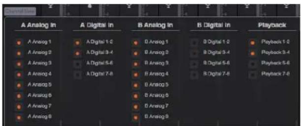
Channel View Button - Show the Channel View pop-up to view/hide various channels.
* Channels are disabled when hidden so audio signal will not pass to the Mixers.
- Analog Input Channels - Corresponds to the physical analog input connections on your Symphony I/O Mk II.
- Digital Input Channels - Corresponds to the physical digital input connections on your Symphony I/O Mk II.
- Playback Channels - Corresponds to the virtual signal path from your Mac's software outputs.
Symphony I/O Mk II - User's Guide Page 36
-
Mixer 1 - Signal from each channel can be sent through this mixer by raising the corresponding Mixer 1 Channel Fader.
-
This mixer's Master signal can then be selected as a source for the Headphones or Speaker outputs, providing a low-latency direct monitoring signal path.
- This mixer can also be sent back into the computer as a separate stereo input available in your DAW.
-
The faders on this mixer affect the fader send signal of the other Mixers and FX Send when the Pre Fader button is not engaged.
-
Mixers 2, 3, 4 - Signal from each channel can be sent through these mixers by raising the individual Mixer 2, 3, or 4 Channel Fader.
- This mixer's Master signal can then be selected as a source for the Headphones or Speaker outputs providing a low-latency direct monitoring signal path.
- FX Send - Signal from each channel can be sent through this mixer by raising the individual FX Send Channel Fader.
•This Mixer is sent back into the computer where it shows up as
an extra stereo input available in your DAW. By using this input on an Aux track that has a Reverb or Delay or other effects plugin, effects can be applied to a Direct Monitoring situation which would otherwise be completely dry of effects.
7. Pre Fader Button
- When engaged, the channel signal from the mixer 2, 3, or FX Send mixer is sent to that mixer's Master fader based only on that mixer's channel fader level. This signal level is not affected by the position of the Mixer 1 fader (Pre-fader).
-
When not engaged (Post-fader), the channel signal from this mixer will change based on the Mixer 1 fader position. In other words, moving the Mixer 1 fader on this same channel will alter the signal level going to the mixer 2, 3 or FX Send mixer master.
-
Mixer View buttons - View or Hide mixers using this button.
*Mixers are always ACTIVE. A mix will continue working even when hidden.
-
Channel Fader - Set the level of the channel signal in the mixer master stereo output.
-
Channel Pan Control - Set the left-right placement of the channel signal in the mixer master stereo output. Option-click to reset the pan to center (0) or Option+Command-click to set all pans in that mixer to center (0).
-
Channel Mute button - Cut the signal routing to the mixer stereo output. Command-click to cut all channels
- Mix Solo button - Mute all channels that do not have this solo button engaged in this mixer. Command-click to solo all channels.
Note: Engage Solo-Safe mode on a channel by Control-Clicking the Solo button on a channel. This prevents this channel from being muted when another channel in the mixer has solo engaged.

A solo-safe engaged track will display a colored "S" within the Solo button
- Channel Mono/Stereo button - Set the channel for a mono or stereo signal path. When set to stereo, odd-even adjacent channels are combined.
- Channel Aux Label - This secondary label is a convenient way to enter session-specific information, such as the performer whose input appears on the channel. This label is not transmitted to the audio software (DAW).
Monitor/Output Section
The Monitor/Output Section is where you select what you hear in the outputs, and control the volume of the various outputs. The Output Level Meters are also a useful diagnostic tool to see if signal should be present at the various outputs.
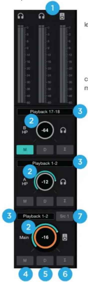
- Output Level Meters - Displayed the output level. Is not affected by the output level control.
- Output Level Control - Set the the output level. Is not affected by the output level
- Output Source Selector - Selects the sound source for each output.
- Output Mute Button - Mutes the output
- Output Dim Button - Reduces the output listening level by -15dB
- Sum-to-Mono button - Collapse left and right signals to mono at the output. This combined signal is sent through both Left and Right Outputs and is useful for verifying the mono-compatibility of a stereo mix.
-
Main Source Toggle Button- Toggle between two different Main Source settings. Toggle to Src 1 (Source 1) and select the first source in the Main Source Dropdown; toggle to Src 2 (Source 2) and select a second source. Useful for comparing different mixes or to playback from iTunes.
-
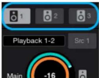
Speaker Set Select Button - Only shown when the the Devices Sidebar > Main Output Format is set to "2 Speaker Sets" or "3 Speaker Sets".
-
Click one button to activate that set
- Command+Click to activate multiple sets simultaneously.
Remote Window
The Remote window provides settings to configure the optional Apogee Control hardware remote control. To open the Remote window choose Window > Remote, type Command+4, or click on the Remote toolbar button.
flowchart
graph TD
    A["1 Clear Meters"] --> B["2 Dim Speakers"]
    B --> C["3 Toggle Spkr Sets"]
    C --> D["4 Toggle Main Src"]
    E["A Launch Sym I/O Control"] --> F["B Mono Speakers"]
    F --> G["C Set Main Out to Reference"]
    G --> H["D Momentary Talkback"]
    I["Control Knob\nMute All Outputs"] --> A
    I --> B
    I --> C
    I --> D
The nine buttons in the window - 1-4, A-D and Control Knob - are used to define the function of corresponding hardware Function buttons.
The following functions are available for all buttons:
None - When a button is assigned to None, it does nothing.
Mute Panic - Mute the headphone and Speaker outputs of all connected units. - Tapping the button again doesn't un-mute the signal - it must be un-muted in Symphony Control software, Touch Panel, or the Control hardware remote.
Mute Speakers - Mute the Main speaker output.
Mute Headphones - Mute the Headphone outputs of all connected units.
Mute All Outputs - Mute the Speaker and all Headphone outputs.
Mute Toggle Headphone/Speaker - Toggle between two states:
- All Headphone outputs muted and the Speaker output unmuted
- All Headphone outputs unmuted and the Speaker output muted.
- When recording in the same room as speakers, this function provides one button switching between recording with headphones and listening back over speakers
Dim Speakers - Lower the Speaker output by 15dB.
Dim Headphones - Lower the Headphone outputs of all connected units by 15dB.
Dim All Outputs - Lower the Speaker and all headphone outputs by 15dB.
Mono Speakers - Sum the stereo Speaker output to mono.
Mono Headphones - Sum the Headphone outputs of all connected interfaces to mono.
Mono All Outputs - Dim the Speaker and all Headphone outputs.
Toggle Speaker Sets - Toggle playback between Speaker Sets; when Main Output Format (Device sidebar) is set to 2 or 3 Speaker Sets.
Select Speaker Set 1 - Selects the first speaker set; when Main Output Format (Device sidebar) is set to 2 or 3 Speaker Sets.
Select Speaker Set 2 - Selects the second speaker set when Main Output Format (Device sidebar) is set to 2 or 3 Speaker Sets.
Select Speaker Set 3 - Selects the third speaker set; when Main Output Format (Device sidebar) is set to 3 Speaker Sets.
Toggle Main Source - Toggles between the two selectable Main Output sources
Set Main Out to Reference Level - Set the Main output level to a predetermined reference level, from -64 to 0 dB.
Symphony I/O Mk II - User's Guide Page 39
| None |
| Mute Panic Mute Speakers Mute Headphones Mute All Outputs Mute Toggle Headphone/Speaker |
| Dim Speakers Dim Headphones Dim All Outputs |
| Mono Speakers Mono Headphones Mono All Outputs |
| Toggle Speaker Sets Select Speaker Set 1 Select Speaker Set 2 Select Speaker Set 3 Toggle Main Source Set Main Out to Reference Level |
| Clear Meters Toggle Talkback Momentary Talkback |
| Analog Input Level Digital Reference Level 48V Phantom Power Group Soft Limit Polarity High Pass Filter Insert |
| Select Input 1 Select Input 2 Select Input 3 Select Input 4 Select Input 5 Select Input 6 Select Input 7 Select Input 8 Toggle Device |
| Launch Symphony I/O Control |
- To determine the reference level, use an external audio measurement to and set the Main Out control to generate the desired SPL level. Once Main Out is set, then assign a Function button to "Set Main Out to Reference Level". Now, when that button is pushed, Main Out jumps to the saved level.
Clear Meters - Clear held peak and overs from Symphony Control software level meters.
Toggle Talkback - Turn the Talkback function on indefinitely until the button is tapped a second time to turn it off.
Momentary Talkback - Turn the Talkback function on only when the button is held down. Releasing the button turns Talkback off.
Analog Input Level - Toggle through an input's Analog Level settings (+4 dBu, -10 dBV, Mic, Instrument) when that input is selected for control. If the Headphone or Speaker output is selected for control and a button assigned to Analog Input Level is tapped, all LEDs flash for a moment to indicate an invalid operation.
Digital Reference Level - Toggle through the Digital Reference Levels (-16dBfs, -18dBfs, etc.) when the input is selected for control and the Analog Input Level is set to +4dBu or -10dBV.
*48V Phantom Power - Toggle 48V Phantom Power on/off for the input selected for control
*Group - Toggle Group on/off for the input selected for control
Soft Limit - Toggle Soft Limit on/off for the input selected for control
Polarity - Toggle Polarity Inversion on/off for the input selected for control
*High Pass Filter - Toggle a 80Hz, 12dB/octave high-pass filter for the input selected for control
*Insert - Toggle insert for the input selected for control (8 Mic Pre card only).
Select Input 1..8 - Select the designated input (1-8) for control. When two interfaces are connected, use the Toggle Device setting to toggle between Interface A 1-8 and Interface B 1-8.
Toggle Device - Toggle the interface selected for control when two interfaces are connected. By setting the 8 Function buttons to Select Input 1, Select Input 2, etc and setting the Control Knob to Toggle Device, it's possible to access both interfaces' mic pre gain setting with only a few button taps.
Launch Symphony Control - Launch Symphony Control software or, if software is already launched, bring the app into keyboard focus.
* Only available if have 8 Mic Pre card installed
| None |
| Mute Panic Mute Speakers Mute Headphones Mute All Outputs Mute Toggle Headphone/Speaker |
| Dim Speakers Dim Headphones Dim All Outputs |
| Mono Speakers Mono Headphones Mono All Outputs |
| Toggle Speaker Sets Select Speaker Set 1 Select Speaker Set 2 Select Speaker Set 3 Toggle Main Source Set Main Out to Reference Level |
| Clear Meters Toggle Talkback Momentary Talkback |
| Analog Input Level Digital Reference Level 48V Phantom Power Group Soft Limit Polarity High Pass Filter Insert |
| Select Input 1 Select Input 2 Select Input 3 Select Input 4 Select Input 5 Select Input 6 Select Input 7 Select Input 8 Toggle Device |
| Launch Symphony I/O Control |
Hover Help Window
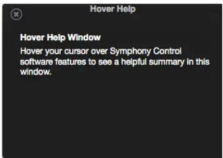
For specific information about Symphony Control's features, open the Help window and hover your Mac's pointer above each setting to see a helpful summary.
Menu Bar Menus
Symphony Control Menu
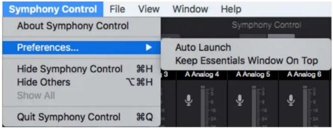
About Symphony Control - Choose this menu item to display version information for all hardware connected and software installed on your Mac.
Preferences > Auto Launch - Choose this menu item to launch Symphony Control when an Symphony I/O Mk II Thunderbolt interface is connected to the computer.
Preferences > Keep Essentials Window On Top - Choose this menu item to prevent the Symphony Control Essentials window from being hidden behind other application windows.
Hide Symphony Control - Choose this menu item to hide the Symphony Control application.
Hide Others - Choose this menu item to hide all other open applications
Show All - If any open applications have been hidden, choose this menu item to reveal all open applications.
Quit Symphony Control - Choose this menu item to quit Symphony Control.
File Menu
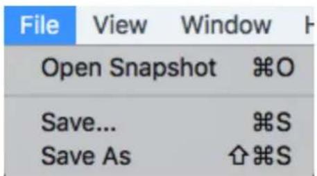
Open Snapshot - Choose this menu item to open a user-saved snapshot template file on your computer.
Save - Choose this menu item to save a user-customized Snapshot file to a location on your computer.
Save As - Choose this menu item to save a customized Snapshot file in a new name or new location on your computer.
View Menu
System Settings - Choose this menu item to open the System Settings sidebar
Device Settings - Choose this menu item to open the Device Settings sidebar
Mixer View - Choose this menu item to open the Mixer view of the Primary Window
Symphony I/O Mk II - User's Guide Page 41
| View | Window | Help |
| System Settings | F | |
| Device Settings | D | |
| √ Mixer View | M | |
| I/O View | I | |
| Enter Full Screen | ||
I/O View - Choose this menu item to open the I/O View of the Primary Window
Enter Full Screen - Choose this menu item to expand Symphony Control to fill the display screen.
Window Menu
| Window | Help |
| Minimize | |
| Zoom | |
| Close | W |
| Bring All to Front | |
| Essentials | 1 |
| √ Primary | 2 |
| Hover Help | 3 |
| Remote | 4 |
Selecting an item in the Window Menu switches to a view of that selection.
Help Menu
| Help |
| Search |
| Hover HelpSymphony Support OnlineFirmware Updater |
Use the Search Field to search for a specific menu item.
Symphony Support Online - Select this menu item to be taken to the Apogee website's Support page for Symphony I/O Mk II.
Monitor Control Center
Symphony I/O Mk II is equipped with several monitoring features to provide for your monitoring needs.
Headphones
Using the same Constant Current Drive technology as found in Groove, the headphones outputs of Symphony IO Mk II dynamically compensates for the nonlinearities – acoustic, mechanical or electrical – of any connected headphones, resulting in lower distortion and a more linear frequency response.
Monitor Outputs
Symphony I/O Mk II has the ability to control the volume of studio monitor speakers that are connected directly to the analog outputs 1-2. This control can be expanded to include up to 3 stereo speaker sets, or a 5.1, 7.1, or even an 11.1 surround speaker setup. It can also be set to a fixed line-level output if using an external monitor control system such as a mixer or console.
How to set the Monitor Outputs for Stereo Speakers
- Open Symphony Control and click the Device button to reveal the Device Sidebar

- Under Main Output Format, select "Speaker"
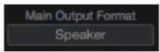
- Adjust the Main Output volume or analog outputs 1-2 with the Main volume knob in Symphony Control's Monitor Section.
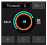
How to set the Monitor Outputs as a fixed Line-Out
This setting changes the Monitor Outputs from a variable volume controlled by the Output Controller knob to a fixed output at the full +4dBu or -10dBV reference level. This setting is convenient for connecting Symphony to an external monitor control device such as a mixer or control center.
- Open Symphony Control and click the Device button to reveal the Device Sidebar

- Under Main Output Format, select select "Line".
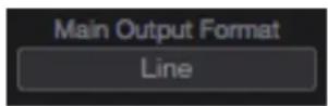
Note: This disable's Ensemble's Monitor Output level control.
How to setup and use Multiple Speaker Sets
It is possible to connect up to three pairs of speaker monitors and toggle between them. This is very useful to check how a mix sounds through different speakers and systems.
- Connect the first pair of speakers to Analog Out 1/2, the second pair to Analog Out 3/4, and if desired a third pair to Analog Out 5/6
- Open Symphony Control and click the Device button to reveal the Device Sidebar

- From the Speaker Output Select drop-down box, select "2 Speaker Sets" or "3 Speaker Sets".
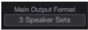
- Click the Speaker Set 1, 2, or 3 button to select which speaker set is active.
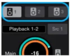
Note: To activate multiple speaker sets simultaneously, hold down [command ⌘] and select another speaker set button.
How to connect and configure a Surround Speaker Setup
When using Symphony with a surround speaker setup, the first set of outputs can be configured as speaker outputs suitable for connection to a 5.1, 7.1, or 9.1, or 11.1 speaker system depending on analog outputs you have available. With this configuration, turning the Output Controller knob will adjust all applicable line-outputs simultaneously.
-
Connect your speakers to Symphony's analog outputs. A standard 5.1 surround setup is routed as follows:
-
Output 1: Front Left
• Output 2: Front Right -
Output 3: Center
• Output 4: Sub-woofer
• Output 5: Left Surround
• Output 6: Right Surround -
Open Symphony Control and click the Device button to reveal the Device Sidebar

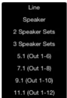
- From the Main Output Format drop-down box, select your desired surround configuration.
Note:
- Must have at least 8 analog outputs for the 7.1 option to become available
- Requires at least 10 analog outputs for 9.1 option to become available
- Requires at least 12 analog outputs for 11.1 option to become available
Talkback

- The talkback feature is activated by holding down the Talkback button in the Symphony Control Toolbar.
- It can also be activated by an assignable button on the optional Control hardware remote (pg 39)
- When talkback is activated, the monitor outputs are automatically dimmed (-15dB).
Selecting the Talkback Source
There are two major sources you can use for Talkback:
- Symphony Input 1
- Any CoreAudio input device on your Mac.
- If the device appears on the INPUT list of Mac Sound Preferences, it can be used as the talkback source. Examples of such devices are your Mac's built-in mic, a USB mic, an Apogee Duet, the line-input jack on the Mac, etc.
*Note, if using multi-channel CoreAudio device such as Duet, Talkback will always use input 1 of that device.
To select the talkback source:
- Open Symphony Control and click the System button to reveal the system sidebar.

- Under Talkback Source, select your device.

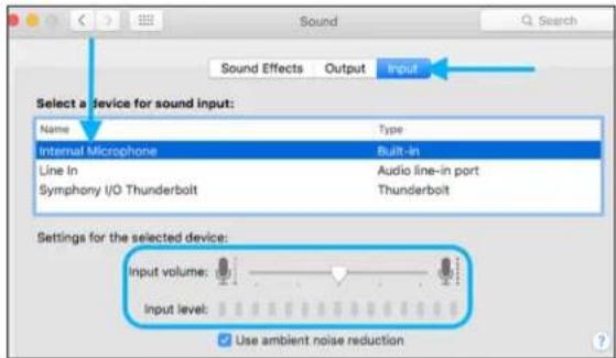
If choosing a device such as Apogee Mic or Duet, the talkback mic's gain is controlled on that device. If choosing the Mac's built-in mic or line-in, the input gain is controlled through the Mac Sound Preferences:
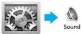
- To adjust the Mac's built-in microphone's gain, open Mac system Preferences > Sound.
- In the INPUT tab, select Internal Microphone from the list, then use the Input Volume Slider to adjust the mic's gain.
Choosing the Talkback Destination
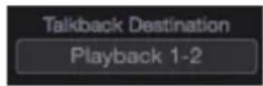
The Talkback can be sent to any Playback channel. From there it can be sent directly to the headphone or main outputs, or can be directed through any of the Mixers first.
To select the Talkback Destination:
- Open Symphony Control and click the System button to reveal the system sidebar.

- Under Talkback Destination, select your desired Playback channel.
Standalone Functionality
When the Symphony I/O Mk II is not connected to a Mac, it functions in a standalone mode.
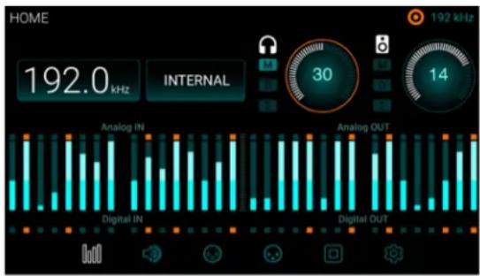
Most of the functions of the unit can be adjusted and controlled from the front-panel touch screen, and audio will be able to pass through the various inputs and outputs of the device. Here are the display differences between regular and standalone modes:
HOME Screen
The Sample Rate and Clock Source are now selectable buttons:
bar
| Category | Analog IN (kHz) | Analog OUT (kHz) | | :--- | :--- | :--- | | Analog IN | 192.0 | 30 | | Digital IN | 192.0 | 14 |Touch the Sample Rate button - Amenu appears allowing you to select any of the Symphony I/O Mk II's sample rates.
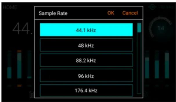
bar
| Sample Rate | | :--- | | 44.1 kHz | | 48 kHz | | 88.2 kHz | | 96 kHz | | 176.4 kHz |Touch the Clock Source button - Select between internal, or various external clock sources.
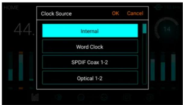
SETTINGS Screen > Configuration tab
In Standalone Mode, buttons for WC IN Termination and Standalone Routing appear:
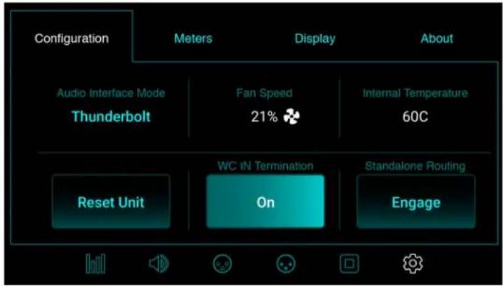
WC IN Termination- When Clock Source is set to Word Clock, this button appears. It activates termination of the Word Clock input.
Standalone Routing - Engages a fixed routing of the audio signal between the analog and digital I/O. How it is routed depends on the module card installed.
8x8 module card Standalone Routing options:
- Analog inputs are routed to Optical or AES digital outputs.
- AES or Optical digital inputs are routed to Analog Outputs
16x16 module card Standalone Routing options:
- Analog inputs are routed to analog outputs
2x6 module card Standalone Routing options:
A-tp-D and Opt. In to Ana. Out
- The 2 analog inputs are mirrored to AES & Optical Outputs 1-2
- Optical Inputs 1-6 are routed to Analog Output 1-6
A-to-D and AES In to Ana. Out
- The 2 analog inputs are mirrored to AES & Optical Outputs 1-2
- The 2-ch AES inputs are mirrored to Analog Outputs 1-2, 3-4, 5-6
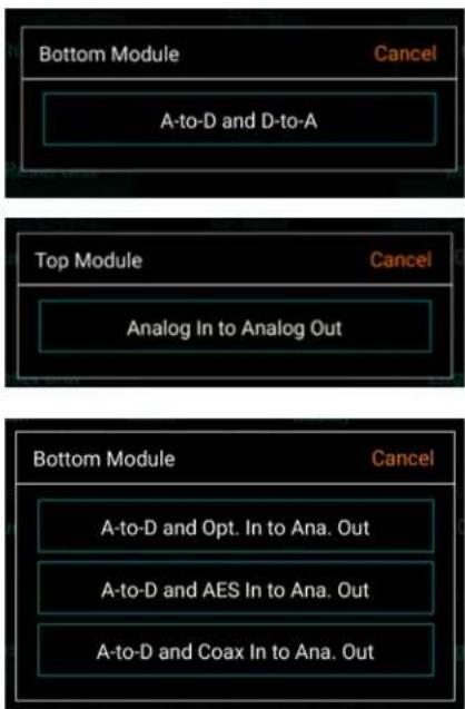
A-to-D and Coax In to Ana. Out
- The 2 analog inputs are mirrored to AES & Optical Outputs 1-2
- The 2-ch Coax inputs are mirrored to Analog Outputs 1-2, 3-4, 5-6
Configure Complex Standalone Routing using Symphony Control
The unit can be configured as a line-mixer using the Symphony Control software. These settings are then retained when the Thunderbolt cable is disconnected. This is especially useful with the 2x6 and 16x16 module cards since there is no 1-to-1 correlation between analog and digital I/O like on the 8x8 module.
-
Open Symphony Control software and go to the I/O section of the Primary Window.
-
In the Output Section, choose the Source for any pair of analog outputs.

* Do not choose Playbacks as these come from your Mac computer which won't be available after disconnecting the Thunderbolt cable.
- Mixer - Various inputs can be combined together using one or more of the 4 Symphony Control mixers.
- In this way, all 16 inputs on the 16x16 module can be mixed and routed to a single stereo output 1-2.
- Hardware Inputs - Any input pair can be routed to any Analog Output pair.
- If you want digital input 5-6 to show up on analog output 1-2, you can select that here.
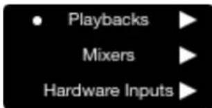
Once the desired routing is made, disconnect the Thunderbolt cable and these settings will be retained until they are changed, the Standalone Routing button is engaged, or the unit is Factory Reset.
Clocking with External Equipment
When connecting digital audio cables between Symphony and another digital audio device, a clocking relationship must also be set. Whether connecting two or more devices, one must be set as the clock master, and all other devices must be set as clock slaves.Configure Symphony as Clock Master
- Open Symphony Control and select the System Sidebar button.
- Set Clock Source to "Internal".
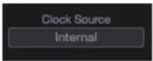
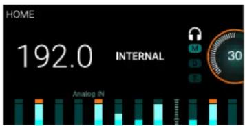
- When Symphony is using it's internal clock, the Home display will show "INTERNAL".
bar
| Category | Value | |---|---| | HOME | 192.0 | | ANALOG IN | 30 | | Internal | 30 |Clock signal is sent to all of Symphony's digital audio outputs and BNC Word Clock output.
- Connect a digital audio cable (optical or coaxial) out of Symphony and into the external equipment. Or connect a BNC Word Clock cable from the OUT of Symphony to the IN of the external equipment.
- Make the appropriate settings on the external equipment to set it as a slave.
- The sample rate must match on both devices. Though the Slave device may automatically switch to the appropriate sample rate, this may not always occur and the sample rate will need to be set manually.
Configure Symphony as Clock Slave
- Set the external device as the clock master.
- Connect a digital audio cable (optical or coaxial) out of the external device and into Symphony. Or connect a BNC Word Clock* cable out of the external gear to Symphony's BNC IN port.
- Open Symphony Control and select the System Sidebar button.
- In the Clocking Section, set Clock Source to the appropriate external connection.
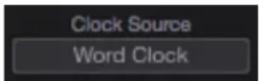
- Set the Clock Source to "Word Clock" when using a BNC word clock cable. Symphony's front panel will also reflect the source.
* BNC is the preferred method of transferring digital clock. Use this connection whenever possible and make sure to follow appropriate termination practices.
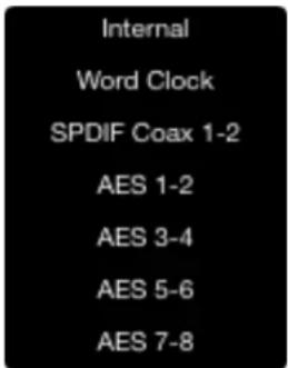
- Set the Clock Source to "ADAT", "SMUX", "AES", "SPDIF Optical", or whatever digital inputs are available on the module card(s) installed in your Symphony I/O Mk II. Symphony's front panel will also reflect the source.
If Symphony doesn't receive or is unable to lock to a external clock source, the display's sample rate will blink. When this happens, check your connections for a bad or misconfigured cable, and make sure the sample rate of the master and slave devices are set to the same value.
Reference
Understanding Latency
What is latency?
When recording with most computer-based digital audio applications, a delay between the input and output of the recording system often disturbs the timing of the musicians who are performing. This delay, known at latency, means that the musician hears the notes he produces a few milliseconds after having produced them. As anyone who has spoken on a phone call with echo knows, relatively short delays can confuse the timing of any conversation, spoken or musical.
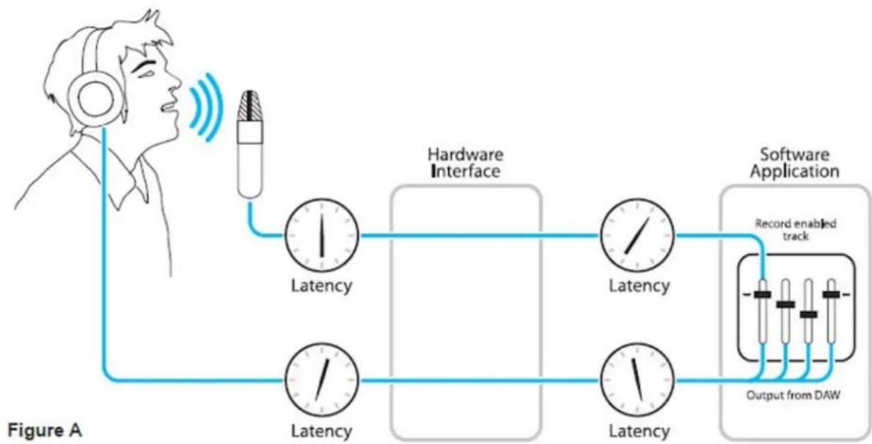
To illustrate the effect of latency, Figure A depicts the typical signal path of a vocal overdub session. A vocalist sings into a microphone, which is routed through a hardware interface to the audio software application for recording. In the software application, the vocalist's live signal is mixed with the playback of previously recorded tracks, and routed back through the hardware interface to the vocalist's headphones. Because of the audio application's latency, the vocalist hears his performance delayed by several milliseconds in his headphones.
flowchart
graph LR
    A["Headphones"] --> B["Audio Signal"]
    B --> C["Hardware Interface"]
    C --> D["Software Application"]
    D --> E["Record enabled track"]
    E --> F["Output from DAW"]
    C --> G["Latency"]
    D --> H["Latency"]
    G --> I["Latency"]
    H --> J["Latency"]
How does Symphony Control resolve latency?
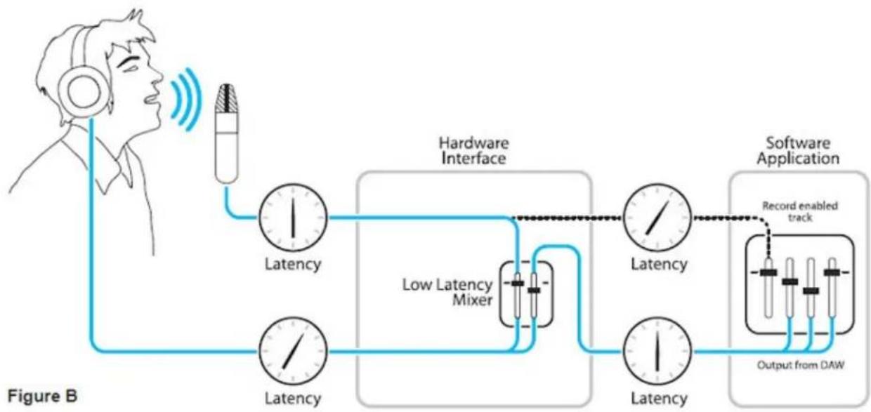
By routing the hardware input directly to the hardware output and mixing in playback as shown in Figure B, it's possible to create a headphone listening signal with a much shorter delay.
First, the signal being recorded (in this case, a vocal mic) is split in the hardware interface and routed to both the software application for recording and directly back to the hardware outputs without going through the latency-inducing software; this creates a low latency path from mic to headphones. Next, a stereo mix of playback tracks is routed to the low latency mixer and combined with the hardware input(s). This allows the performer to hear both himself without a confusing delay plus the playback needed for overdubbing.
Note that the software application's mixer is used to set a stereo mix of playback tracks while the low latency mixer is used to set the balance between the stereo playback mix and the hardware inputs.
flowchart
graph LR
    A["Headphones"] --> B["Antenna"]
    B --> C["Hardware Interface"]
    C --> D["Low Latency Mixer"]
    D --> E["Software Application"]
    E --> F["Output from DAW"]
    C --> G["Latency"]
    D --> H["Latency"]
    E --> I["Latency"]
    G --> J["Record enabled track"]
    H --> J
    I --> J
Do I need the Symphony Control Mixer?
The Symphony Control mixers serves to provide a low latency listening mix while recording. Therefore if you're using Symphony to listen to iTunes or audio from another program, there's no need to use the mixer.
It's also possible that the latency of your particular recording system is low enough to be unnoticeable by you or other performers, especially since Symphony uses the very efficient Thunderbolt™ 2 Technology. If you've set your audio software's input/output buffers according to the guidelines below and latency doesn't bother you or other performers, there's no need to use the Symphony Control mixers.
How do I set my software's I/O Buffer?
The I/O Buffer setting found in most audio software is one of the most crucial, but often ignored, settings in a Mac-based recording system. When choosing a buffer setting, a compromise between the latency through the application and the amount of computer processor power accessible to the application must be made.
A lower Buffer setting results in lower latency but less available processing power. If the application can't access enough processor power, processor overruns may occur, resulting in audible clicks and pops or error messages that interrupt playback and recording.
A higher Buffer setting, on the other hand, results in greater amount of accessible processor power (i.e. less chance of overruns) but increases the latency. Determining the best setting requires some trial-and-error in order to find the best compromise.
Keep in mind that as tracks and plug-ins are added to a software session, processor requirements increase. Thus, the buffer setting that works during the early stages of a session might result in processor overruns during later stages.
The best strategy is to set the buffer to a lower setting during recording and accept certain limitations on plug-in usage, and then raise the buffer during mixing to utilize the computer's full processor power when latency isn't an issue.
With the processing power of today's Macs, you may find that adjustment of the Buffer isn't necessary, and you c leave it at a setting for low latency and still access a sufficient amount of processing power when adding tracks and plug-ins. If you do encounter clicks, pops or software errors, don't hesitate to experiment with the Buffer setting.
Soft Limit
Soft Limit is Apogee's proprietary analog process for taming transients before A/D conversion. By gently rounding transients in a transparent manner, it's possible to maximize level BEFORE the A/D conversion stage and prevent unwanted distortion from clipping.
Soft Limit Settings
Soft Limit may be engaged on each analog input in Symphony Control's Input tab window. On the 16x16, 16x16mkII, and 8x8mkII IO Modules, soft limit functionality is restricted to On and Off. The On setting corresponds to the -4 dBfs option.
On other Original Symphony I/O Modules. The following settings are available:
- -2 dBfs - Soft Limit begins to attenuate transient peaks at a level of -2 dBfs. This is the most transparent Soft Limit setting.
- -4 dBfs - Soft Limit begins to attenuate transient peaks at a level of -4 dBfs. This is the threshold of previous implementations of Soft Limit.
- Soft Saturate - a lower threshold, plus asymmetrical clipping in a manner similar to tube circuits.
- Soft Crush - The most extreme setting, where audible distortion and dirty mojo are required. Take that, drums!
When to use Soft Limit
Soft Limit is an analog process that instantaneously rounds transient peaks beginning at -4dbfs. For all intents and purposes attack and release times may be considered instantaneous. As with any peak reduction device working at such fast time constants, Soft Limit is most effective with signals whose peak information is much greater than its average (or RMS) information, such as drums, percussion and plucked instruments. Soft Limit may not be the appropriate choice for limiting signals whose crest factor (peak to RMS ratio) is low, such as bass or organ.
Pin Out Diagrams
Analog and Inserts
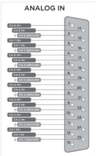
Pinout for Analog IN and INSERTS RETURN 1-8 (ic Pre I/O Module)
bar
ANALOG IN | Channel | Count | |---|---| | CH 8 IN+ | 1 | | CH 8 IN- | 2 | | CH 8 GROUND | 15 | | CH 7 IN+ | 3 | | CH 7 IN- | 16 | | CH 7 GROUND | 4 | | CH 6 IN+ | 5 | | CH 6 IN- | 17 | | CH 6 GROUND | 18 | | CH 5 IN+ | 6 | | CH 5 IN- | 19 | | CH 5 GROUND | 7 | | CH 4 IN+ | 8 | | CH 4 IN- | 20 | | CH 4 GROUND | 21 | | CH 3 IN+ | 9 | | CH 3 IN- | 22 | | CH 3 GROUND | 10 | | CH 2 IN+ | 11 | | CH 2 IN- | 23 | | CH 2 GROUND | 24 | | CH 1 IN+ | 12 | | CH 1 IN- | 25 | | CH 1 GROUND | 13 |Pinout for Analog OUT and INSERTS SEND 1-8 (Mic Pre I/O Module)
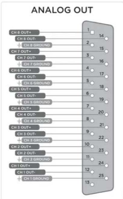
bar
ANALOG OUT | Channel | Signal | |---|---| | CH 8 OUT+ | 1 | | CH 8 OUT- | 2 | | CH 8 GROUND | 15 | | CH 7 OUT+ | 3 | | CH 7 OUT- | 16 | | CH 7 GROUND | 4 | | CH 6 OUT+ | 17 | | CH 6 OUT- | 5 | | CH 6 GROUND | 18 | | CH 5 OUT+ | 6 | | CH 5 OUT- | 19 | | CH 5 GROUND | 7 | | CH 4 OUT+ | 20 | | CH 4 OUT- | 8 | | CH 4 GROUND | 21 | | CH 3 OUT+ | 9 | | CH 3 OUT- | 22 | | CH 3 GROUND | 10 | | CH 2 OUT+ | 23 | | CH 2 OUT- | 11 | | CH 2 GROUND | 24 | | CH 1 OUT+ | 12 | | CH 1 OUT- | 25 | | CH 1 GROUND | 13 |Symphony I/O Mk II - User's Guide Page 54
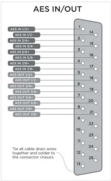
AES IN/OUT
bar
AES IN/OUT | Connection Type | Number of Connections | | :--- | :--- | | AES IN 1/2+ | 14 | | AES IN 1/2- | 15 | | AES IN 3/4+ | 16 | | AES IN 3/4- | 17 | | AES IN 5/6+ | 18 | | AES IN 5/6- | 19 | | AES IN 7/8+ | 20 | | AES IN 7/8- | 21 | | AES OUT 1/2+ | 22 | | AES OUT 1/2- | 23 | | AES OUT 3/4+ | 24 | | AES OUT 3/4- | 25 | | AES OUT 5/6+ | 26 | | AES OUT 5/6- | 27 | | AES OUT 7/8+ | 28 | | AES OUT 7/8- | 29 | Tie all cable drain wires together and solder to the connector chassis.Specifications
System Requirements
• Computer: Intel Thunderbolt™ Equipped Mac
• Memory: 4GB RAM minimum, 8GB recommended
- OS X 10.10 or later
- Thunderbolt cable
*Thunderbolt and the Thunderbolt logo are trademarks of Intel Corporation in the U.S. and/or other countries.
Factory Hardware Reset / Initialize
To return Symphony to the factory default settings:
- Start with Symphony turned off.
- Hold down the Controller knob.
- Turn Symphony on.
- When the Symphony I/O "Resetting" screen clears and the Display shows the HOME screen, let go of the Controller knob.
This completes the hardware reset of Symphony.
Technical Details
| Technical Specifications | |
| Analog to Digital | THD + N: -115dB @22dBu (0.00020%) unweightedDynamic Range: 122dB (A-weighted)Max Input Level: (+4dBu ref): +24dBuMax Input Level: (-10dBV ref): +6dBvFrequency Response @ 44.1kHz sample rate: 10 - 20kHz (+/- 0.05dB)Input Impedance: 10K |
| Digital to Analog | THD + N: -119dB @21dBu (0.00014%) unweightedDyn Range: 126dB (A-weighted)Max Output Levels: ∞ to +24dBuFrequency Response @ 44.1kHz sample rate: DC to 20kHz (+/- 0.05dB)Output Impedance: 25 OhmOutputs are balanced through Apogee's proprietary Perfect Symmetry Circuitry (PSC) |
| Headphone Output | 1 stereo 1/4" headphone output on front panelTHD + N:-110dB @19dBu into 600 Ohm (=80mW)-101dB @14dBu into 32 Ohm (=470mW)Dyn Range: 121dB (A-weighted)Output: Apogee's proprietary Constant Current DriveTM provides smooth frequency response with any headphones |
| Connections | 2 Thunderbolt 2 ports |
| Max Audio Resolution | 24-bit/192 kHz |
General Details
| General | |
| Symphony I/O Mk II Dimensions | Inches: 17.75 (19 with Rack Ears) x 11.5 x 3.5Centimeters: 45 (48.26 with Rack Ears) x 29.2 x 8.9 |
| Symphony I/O Chassis Packaging Box | Inches: 22.875 x 17.75 x 9.25Centimeters: 58.1 x 45.1 x 23.5 |
| I/O Module Packaging Box | Inches: 13.75 x 12.25 x 3.25Centimeters: 34.9 x 31.1 x 8.3 |
| Power | AC IN 90-240VAC, 50-60 Hz, 150W |
Additional Support
General Support
For more information:
• Apogee KnowledgeBase and FAQs
• Apogee Product Registration
• How to contact Apogee Technical Support
Visit: http://www.apogeedigital.com/support/
Apogee Pro Care

natural_image
Generic user avatar icon with a purple tie inside a gray circle (no text or symbols)APOGEE PRO Care
Professional Service Plan
Want priority access and expedited repair? Consider an Apogee ProCare membership.
It's never been easier to get back to work.
As a ProCare member you'll have premium access to Apogee's world-class technical support group for the life of your agreement. The contract is fully transferable by the original registered owner of the agreement. All Apogee support technicians reside and are continuously trained at Apogee Electronics, Santa Monica, CA.
Learn more at: www.apogeedigital.com/apogee-procare
Warranty Information and Legal Notices
Symphony Warranty Information and Legal Notices
Registration and Warranty Information
Be sure to register your Symphony, either by filling in the enclosed Registration Card or by completing the on-line registration form at our Web site: www.apogeedigital.com/support/contact-support
If you do so, Apogee can contact you with any update information. As enhancements and upgrades are developed, you will be contacted at the registration address. Firmware updates are free for the first year of ownership unless otherwise stated.
Please address any inquiries to your dealer or directly to Apogee at:
APOGEE ELECTRONICS CORPORATION
1715 Berkeley St Santa Monica, CA 90404, USA
web: www.apogeedigital.com/support
APOGEE ELECTRONICS CORPORATION warrants this product to be free of defects in material and manufacture under normal use for a period of 12 months. The term of this warranty begins on the date of sale to the purchaser. Units returned for warranty repair to Apogee or an authorized Apogee warranty repair facility will be repaired or replaced at the manufacturer's option, free of charge.
ALL UNITS RETURNED TO APOGEE OR AN AUTHORIZED APOGEE REPAIR FACILITY MUST BE PREPAID, INSURED AND PROPERLY PACKAGED, PREFERABLY IN THEIR ORIGINAL BOX.
Apogee reserves the right to change or improve design at any time without prior notification. Design changes are not implemented retroactively, and the incorporation of design changes into future units does not imply the availability of an upgrade to existing units. This warranty is void if Apogee determines, in its sole business judgment, the defect to be the result of abuse, neglect, alteration or attempted repair by unauthorized personnel. The warranties set forth above are in lieu of all other warranties, expressed or implied, and Apogee specifically disclaims any and all implied warranty of merchantability or of fitness for a particular purpose. The buyer acknowledges and agrees that in no event shall the company be held liable for any special, indirect, incidental or consequential damages, or for injury, loss or damage sustained by any person or property, that may result from this product failing to operate correctly at any time.
USA: Some states do not allow for the exclusion or limitation of implied warranties or liability for incidental or consequential damage, so the above exclusion may not apply to you. This warranty gives you specific legal rights, and you may have other rights which vary from state to state.
Service Information
Symphony contains no user-serviceable components; refer to qualified service personnel for repair or upgrade. Your warranty will be voided if you tamper with the internal components. If you have any questions with regard to the above, please contact Apogee.
In the event your Symphony needs to be upgraded or repaired, it is necessary to contact Apogee prior to shipping, and a Return Materials Authorization (RMA) number will be assigned. This number will serve as a reference for you and helps facilitate and expedite the return process. Apogee requires that shipments be pre-paid and insured — unless otherwise authorized in advance.
IMPORTANT: ANY SHIPMENT THAT IS NOT PRE-PAID OR IS SENT WITHOUT AN RMA NUMBER WILL NOT BE ACCEPTED.
Warnings
FCC Warning
This equipment has been tested and found to comply with the limits for a Class A digital device, pursuant to Part 15 of the FCC rules. These limits are designed to provide reasonable protection against harmful interference when operated in a commercial environment. This equipment generates, uses, and can radiate radio frequency energy and, if not installed and used in accordance with the instruction manual, may cause harmful interference to radio communications. Operation of this equipment in a residential area is likely to cause harmful interference, in which case the user will be required to take whatever measures necessary to correct the interference at his own expense.
Copyright Notice
Symphony is a computer-based device, and as such contains and uses software in ROMs. This software, and all related documentation, including this User's Guide contain proprietary information which is protected by copyright laws. All rights are reserved. No part of the software and its related documentation may be copied, transferred, or modified. You may not modify, adapt, translate, lease, distribute, resell for profit or create derivative works based on the software and its related documentation or any part thereof without prior written consent from Apogee Electronics Corporation, U.S.A.
Software Notice
Redistribution and use in source and binary forms, with or without modification, are permitted provided that the following conditions are met:
- Redistributions of source code must retain the above copyright notice, this list of conditions and the following disclaimer.
- Redistributions in binary form must reproduce the above copyright notice, this list of conditions and the following disclaimer in the documentation and/or other materials provided with the distribution.
THIS SOFTWARE IS PROVIDED BY THE COPYRIGHT HOLDERS AND CONTRIBUTORS “AS IS” AND ANY EXPRESS OR IMPLIED WARRANTIES, INCLUDING, BUT NOT LIMITED TO, THE IMPLIED WARRANTIES OF MERCHANTABILITY AND FITNESS FOR A PARTICULAR PURPOSE ARE DISCLAIMED. IN NO EVENT SHALL THE COPYRIGHT OWNER OR CONTRIBUTORS BE LIABLE FOR ANY DIRECT, INDIRECT, INCIDENTAL, SPECIAL, EXEMPLARY, OR CONSEQUENTIAL DAMAGES (INCLUDING, BUT NOT LIMITED TO, PROCUREMENT OF SUBSTITUTE GOODS OR SERVICES; LOSS OF USE, DATA, OR PROFITS; OR BUSINESS INTERRUPTION) HOWEVER CAUSED AND ON ANY THEORY OF LIABILITY, WHETHER IN CONTRACT, STRICT LIABILITY, OR TORT (INCLUDING NEGLIGENCE OR OTHERWISE) ARISING IN ANY WAY OUT OF THE USE OF THIS SOFTWARE, EVEN IF ADVISED OF THE POSSIBILITY OF SUCH DAMAGE.
Declarations of Conformity
This device complies with Part 15 of the FCC Rules. Operation is subject to the following two conditions:
- This device may not cause harmful interference
- This device must accept any interference received, including interference that may cause undesired operation.
This equipment has been tested and found to comply with the limits of a Class B digital device, pursuant to Part 15 of the FCC Rules. These limits are designed to provide reasonable protection against harmful interference in a residential installation. This equipment generates, uses and can radiate radio frequency energy and, if not installed and used in accordance with the instructions, may cause harmful interference to radio communications. If this equipment does cause harmful interference to radio or television reception, which can be determined by turning the equipment off and on, the user is encouraged to try to correct the interference by one or more of the following measures:
- Re-orient or relocate the receiving antenna.
- Increase the separation between the equipment and receiver.
- Connect the equipment into an outlet on a different circuit from that to which the receiver is connected.
- Consult the dealer or an experienced radio/TV technician for help.
NOTE: The use of non-shielded cable with this equipment is prohibited.
CAUTION: Changes or modifications not expressly approved by the manufacturer responsible for compliance could void the user's authority to operate the equipment.
Apogee Electronics Corp.
1715 Berkeley Street
Santa Monica, CA 90404, USA
Betty Bennett, CEO.
Industry Canada Notice
Declaration of Conformity - CE
Apogee Electronics Corporation hereby declares that the product, the Symphony, to which this declaration relates, is in material conformity with the following standards or other normative documents:
• EN50081-1/EN55022; 1995
• EN50082-1/IEC 801-2, 3, 4; 1992
following the provisions of:
• 73/23/EEC – Low Voltage Directive
89/336/EEC - EMC Directive
Declaration of Conformity - Japan
Apogee Electronics Corporation hereby declares that Symphony, to which this declaration relates, is in material conformity with the VCCI Class A standard.
Declaration of Conformity - Australia
Apogee Electronics Corporation hereby declares that Symphony is in material conformity with AN/NZS standard requirements.
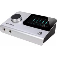
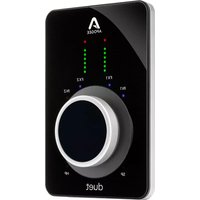


- Apogee Symphony I/O Mk II
- Contents
- Overview 5 ......
- Thunderbolt-Equipped Model 15
- Pro Tools HD Equipped Model....26
- Main Features....28
- Reference 51
- Specifications....56
- Additional Support 58
- Warranty Information and Legal Notices .....59
- Overview
- Introduction
- Features
- Package Contents
- Register your product : apogeedigital.com/register
- Symphony I/O Mk II Panel Tour
- Front Panel
- Rear Panel
- Module Cards
- Mk II Cards
- 8x8 Mk II Module
- To select either Optical or AES digital audio:
- 16x16 Mk II Module
- Compatible Original Cards
- Mic Pre Module
- INPUTS
- OUTPUTS
- 8x8 Analog + 8 AES/Optical IO Module
- Incompatible Original Cards
- Option Cards
- Thunderbolt Card
- Pro Tools HD Option Card
- Control - Hardware Remote
- Microphone button
- Headphone button
- Speaker button
- Control Knob
- Thunderbolt-Equipped Model
- System Requirements
- Setup
- Download and Install Software
- Double-click to launch the Symphony I/O Mk II Installer.pkg
- Making Connections
- Single-Unit:
- Multi-Unit:
- Precautions when powering Symphony On/Off
- Update Symphony Firmware
- Getting Started with Audio Software
- Select Symphony for Mac System Sound Output
- Route Mac System Sound to Different Outputs
- Select Symphony in your DAW
- Select Symphony in Logic Pro X
- Select Symphony in Pro Tools
- Monitoring the Input Signal
- Using your DAW to Monitor
- Enable Input Monitor in Logic Pro X
- Enable Input Monitor in Pro Tools
- Navigating The Front Panel Touchscreen
- Swipe to navigate
- Tap section icons to navigate
- Control knob focus selection
- Muting with the control knob
- HOME
- MONITOR
- INPUT LEVEL
- OUTPUT LEVEL
- DIGITAL I/O
- SETTINGS
- Pro Tools HD Equipped Model
- REFER TO THE SYMPHONY I/O MK II HD ADDENDUM FOR COMPREHENSIVE INFORMATION ON OPERATION OF THE SYMPHONY I/O MK II WHEN EQUIPPED WITH THE HD OPTION CARD.
- Changing to Pro Tools HD Audio Interface Mode:
- Update Symphony Firmware - Pro Tools HD Option Card:
- System Requirements:
- Main Features
- Thunderbolt Audio Interface Mode
- Selecting the Thunderbolt Audio Interface Mode
- Symphony Control
- Essentials Window
- Primary Window
- Tool Bar
- System Sidebar
- Device Sidebar
- I/O View
- Apple Keyboard Navigation Tips
- I/O Channel Section - INPUT
- I/O Channel Section - OUTPUT
- Mix View
- Mixer Section
- Pre Fader Button
- Monitor/Output Section
- Remote Window
- The following functions are available for all buttons:
- Hover Help Window
- Menu Bar Menus
- Symphony Control Menu
- File Menu
- View Menu
- Monitor Control Center
- Headphones
- Monitor Outputs
- How to set the Monitor Outputs for Stereo Speakers
- How to set the Monitor Outputs as a fixed Line-Out
- How to setup and use Multiple Speaker Sets
- How to connect and configure a Surround Speaker Setup
- Note:
- Talkback
- Selecting the Talkback Source
- To select the talkback source:
- Choosing the Talkback Destination
- To select the Talkback Destination:
- Standalone Functionality
- HOME Screen
- SETTINGS Screen > Configuration tab
- A-tp-D and Opt. In to Ana. Out
- A-to-D and AES In to Ana. Out
- A-to-D and Coax In to Ana. Out
- Configure Complex Standalone Routing using Symphony Control
- Clocking with External Equipment
- Configure Symphony as Clock Slave
- Reference
- Understanding Latency
- What is latency?
- How does Symphony Control resolve latency?
- Do I need the Symphony Control Mixer?
- How do I set my software's I/O Buffer?
- Soft Limit
- Soft Limit Settings
- On other Original Symphony I/O Modules. The following settings are available:
- When to use Soft Limit
- Pin Out Diagrams
- Analog and Inserts
- AES IN/OUT
- Specifications
- Factory Hardware Reset / Initialize
- Additional Support
- General Support
- For more information:
- Apogee Pro Care
- Professional Service Plan
- Want priority access and expedited repair? Consider an Apogee ProCare membership.
- It's never been easier to get back to work.
- Warranty Information and Legal Notices
- Symphony Warranty Information and Legal Notices
- Registration and Warranty Information
- ALL UNITS RETURNED TO APOGEE OR AN AUTHORIZED APOGEE REPAIR FACILITY MUST BE PREPAID, INSURED AND PROPERLY PACKAGED, PREFERABLY IN THEIR ORIGINAL BOX.
- Service Information
- Warnings
- FCC Warning
- Copyright Notice
- Software Notice
- Declarations of Conformity
- Industry Canada Notice
- Declaration of Conformity - CE
- Declaration of Conformity - Japan
- Declaration of Conformity - Australia
Brand : Apogee
Model : Symphony I/O Mk II
Category : Hi-Fi System