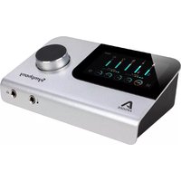
Symphony Desktop - Hi-Fi System Apogee - Free user manual and instructions
Find the device manual for free Symphony Desktop Apogee in PDF.


| Type | USB Audio Interface / DAC / Preamp |
| Brand | Apogee |
| Model | Symphony Desktop |
| Category | Hi-Fi System |
| Dimensions (W x D x H) | 12.0 x 7.5 x 2.0 in (30.5 x 19.0 x 5.1 cm) |
| Weight | 5.9 lbs (2.7 kg) |
| Power Supply | External AC adapter (12V DC, 3A) |
| Sampling Rates | Up to 192 kHz / 24-bit |
| Audio Inputs | 2 x XLR/TRS combo (mic/line), 2 x 1/4" TRS (line), 1 x RCA (unbalanced), 1 x optical (ADAT/SPDIF) |
| Audio Outputs | 2 x XLR (main), 2 x 1/4" TRS (line), 1 x 1/4" headphone (front) |
| Digital I/O | USB-C (audio & power), optical (ADAT/SPDIF), MIDI (in/out via breakout cable) |
| Main Features | USB-C connectivity, low-latency drivers, built-in DSP effects, Apogee Pristine preamps, dedicated app control |
| Compatibility | Mac OS X 10.12+, Windows 10+ (USB 2.0 or higher) |
| Software Included | Apogee Control 2 software, Symphony ECS Channel Strip |
| Maintenance & Cleaning | Use a dry, soft cloth. Avoid solvents. Keep vents clear. |
| Safety | Do not expose to water or extreme temperatures. Use only supplied power adapter. |
| Spare Parts & Repairability | Contact Apogee support for service. User-replaceable power adapter. No internal user-serviceable parts. |
| Warranty | 1 year limited warranty (expandable with registration) |
| General Information | Desktop audio interface designed for professional recording, mixing, and high-quality playback. |
Frequently Asked Questions - Symphony Desktop Apogee
User questions about Symphony Desktop Apogee
0 question about this device. Answer the ones you know or ask your own.
Ask a new question about this device
Download the instructions for your Hi-Fi System in PDF format for free! Find your manual Symphony Desktop - Apogee and take your electronic device back in hand. On this page are published all the documents necessary for the use of your device. Symphony Desktop by Apogee.
USER MANUAL Symphony Desktop Apogee
natural_image
Studio setup with APOGEE audio recording device and computer monitor displaying audio waveform, surrounded by speakers and decorative objects (no readable text or symbols on main components)Symphony Desktop User's Guide
User's Guide v 1.3
Contents
Contents 2
Overview 4
Introduction 4
Features 4
Navigating This User's Guide 7
In the Box 8
System Requirements 8
Register your Product 8
Symphony Desktop Panel Tour 9
Getting Started 10
Installing Apogee Desktop Software 10
macOS Installer 10
Windows 10 Installer 10
iPad Pro/iPhone 11
Connecting Symphony Desktop 12
AC Power 12
Connecting to a Mac or Windows computer 13
Connecting to an iPad Pro (USB-C) 13
Connecting to an iOS Device 13
Update Touch Screen Control 14
On Windows 10: 15
Configure OS to use Symphony Desktop for Audio I/O 16
macOS 16
Windows 10 16
Apple iOS 17
How to Reset Symphony Desktop 17
Connecting Your Studio 18
TFT Touch Screen Control 21
Navigating the Touch screen Interface 21
I/O Views 24
Mixer Views 34
Optical Input Views 35
System Settings Views 36
Shutdown/Display Sleep 38
Apogee Control 2 Software 39
Primary Window 39
Tool Bar 39
System Settings Sidebar 40
Channel Section 42
General Settings 42
Optical IN Channels 43
Playback & Optical Output Channels 44
Mixer Section 45
Monitor/Output Section 46
Menu Bar Menus 47
Apogee Alloy Mic Preamp Emulation 48
Getting Started with the AP-66 48
Getting Started with the AP-57 49
Apogee Channel FX Rack 50
Channel Link 51
Rack Controls 52
Using the Channel FX Plugin 54
DAW Automation and Channel FX 57
Channel FX On/Off Controls 58
Channel FX Mono/Stereo Configuration 59
Channel FX DSP Instance Count 60
Choose Your Symphony Desktop Workflows 61
A Glossary of Important Workflow Concepts 61
Monitoring Workflows 64
Software Monitoring 64
Direct Monitoring 65
DSP Processing Workflows 66
Apogee Alloy Mic Preamp Emulation 66
Print FX 67
Monitor FX & DualPath Monitoring 68
Monitor FX & Software Monitoring 69
Additional Workflows 70
Mix Inputs Before Recording 70
Configuring Your DAW 71
Apple Logic Pro 71
Avid Pro Tools 73
Ableton Live 75
Troubleshooting 77
Specifications 78
Warranty Information and Legal Notices 79
Declarations of Conformity 79
Overview
Introduction
Put the Sound of a Symphony on Your Desktop
Symphony Desktop for Mac, iPad Pro and Windows offers the legendary sound quality of Apogee's flagship Symphony I/O Mk II into an elegant 10x10 audio interface that sits on your desk and fits in your bag. With Symphony Desktop, musicians and producers are empowered to record, overdub and mix with the music industry's most respected AD/DA converters and mic preamps.
By combining superior performance with new features like mic preamp emulation, the Symphony ECS Channel Strip and Clearmountain's Spaces reverb plugins, and ultra low latency recording with hardware DSP and Apogee native FX plugins, Symphony Desktop will amplify your creativity in the studio or on the go, giving your recordings the Apogee quality advantage.
Features
Symphony Analog-to-Digital Conversion
Similar to Symphony I/O MkII, Symphony Desktop's analog-to-digital converter stage features ultra-low distortion, high-slew rate, fully differential analog op-amps plus a cutting edge A/D converter in a performance-enhancing dual-sum configuration. Create with the confidence that every nuance of your analog input is faithfully reproduced in the digital domain.
Symphony Digital-to-Analog Conversion
Symphony Desktop's digital-to-analog stage employs brand new technology to provide uncompromising Symphony DAC performance in a portable product, including a robust ultra-low distortion, high-current output driver. Regardless of downstream connections, Symphony Desktop provides a transparent, widescreen window into the sonic landscape of your mix.
Immersive Touch screen
The immersive TFT touch screen and responsive Control knob gives you total control over all aspects of Symphony Desktop, from input and output levels, mic preamp emulation, low latency mixers and routing. With everything at your fingertips, your music creation and production flows freely, whether you're on a Mac, Windows or iOS platform.
Apogee Alloy Mic Preamp Emulation
Apogee Alloy mic preamp emulation offers analog circuitry plus DSP processing to create the richest, most authentic audio modeling available in an audio interface. Critical aspects of the model such as input impedance, transient profile and distortion characteristics are first implemented in the analog domain, followed by precise and accurate refinement in DSP, for a hybrid result that's greater than the sum of its parts.
The AP-66 emulation is based on the Class A solid-state Neve 1066 mic preamp, with a characteristic low-mid color and slightly compressed transients.
The AP-57 emulation offers the lush, larger-than-life tube saturation of a carefully restored 50s era Ampex 601 preamp.
Innovative Workflows with Hardware DSP
Symphony Desktop includes flexible and powerful onboard hardware DSP processing that supports a wide range of innovative workflows, using the Apogee Channel FX plugin. Whether you're printing your tracks with Apogee Alloy mic preamp emulation or enjoying the benefits of DualPath monitoring, there's a DSP-powered workflow that fits you like a glove.
Apogee Plugins Included
Included with Symphony Desktop is the Symphony ECS Channel Strip plugin. Tuned by Bob Clearmountain, Symphony ECS includes EQ, Compression and Saturation for quick and effective processing when tracking vocals or acoustic instruments.
Also included is the Apogee Clearmountain's Spaces plugin, which reproduces legendary mixer Bob Clearmountain's personalized workflow for creating the distinctive, rich spaces where his mixes live. With the very same echo chamber profiles and processing he's used on countless hit records, Clearmountain's Spaces lets you envelope your tracks in unique and cohesive atmospheres that set your mixes apart.
Zero-Ohm Headphone Outputs
Symphony Desktop has two completely independent ultra low impedance headphone outputs that are individually routable, equipped with dual-sum ESS DACs. Output power range is tailored to the expected type of headphones: the front panel output can drive virtually any headphones, while the rear panel output is specifically designed for high-efficiency headphones.
Advanced Stepped Gain Mic Preamps
At the core of the input stage, Symphony Desktop's mic preamps offer up to 75dB of gain. The preamp design features Apogee's unique Advanced Stepped Gain Architecture to ensure ultra-low noise and distortion regardless of the source, from pounding kick drum to delicate fingerpicking on an acoustic guitar. With variable impedance settings on both mic and instrument inputs, Symphony Desktop optimizes the input stage to better match your specific devices, for deep lows and clear highs. Selectable mic preamp emulation adds character, attitude and a bit of grit to your recordings.
Navigating This User's Guide
A computer-based audio production system built around the Symphony Desktop includes the following components:
- Symphony Desktop Hardware Interface
- Apogee Desktop Control software application
- Apogee Channel FX plus Apogee FX plugins
- Mac, Windows or iOS device plus a Digital audio workstation (DAW) software application
- Microphones and Instruments for recording plus speakers and headphones for listening
This User's Guide will take you through the following steps to integrate the components of your system into a powerful and efficient audio production environment. When text is highlighted in blue, it may be clicked to link to further information in this Guide.
- Download and run the Symphony Desktop Installer, which installs the Apogee Desktop Control application (and driver if required) on your computer (link).
- Connect Symphony Desktop to AC power (required) and to your computer via USB (link).
- Update Touch Screen Control using the included USB thumb drive (link).
- Configure your computer's operating system (OS) to use Symphony Desktop for audio input and output (link).
- Configure your DAW to use Symphony Desktop for audio input and output (link).
- Connect microphones, instruments, headphones, speakers and other audio hardware to Symphony Desktop (link).
- Use Symphony Desktop's top panel TFT touch screen to navigate Input, Output and most System settings (link).
- Use Desktop Control software to navigate all settings, including direct monitor mixing and Apogee Channel FX (link).
- Choose a Monitoring workflow and configure your DAW and Symphony Desktop (link).
- Set up Plugin Processing workflows according to your preference (link).
See the Apogee FX User's Guide (included in the Symphony Desktop Installer download) for information about the Apogee Channel FX and plugins, including the Symphony ECS Channel Strip.
See the Clearmountain's Spaces User's Guide (included in the Symphony Desktop Installer download) for information about the Clearmountain's Spaces plugin.
In the Box
- Symphony Desktop
- Universal Power Supply with US (North America), UK, EU and SAA AC adapters.
- USB-C > USB-C, & USB-C > USB-A cables
- 1Gb USB thumb drive for Touch screen Control updates
- Quick Start Guide
- Warranty Booklet
System Requirements
• macOS 10.14.6 or greater
- Windows 10 20H1 or later
- iOS 13 or greater
• Mac & Windows: 4GB minimum RAM, 8GB Recommended
Register your Product
- Access Apogee's expert Technical Support for free
- Receive important product update information by email
- Take the Customer Satisfaction Survey for a chance to win Apogee gear!
Register Now: www.apogeedigital.com/support/register
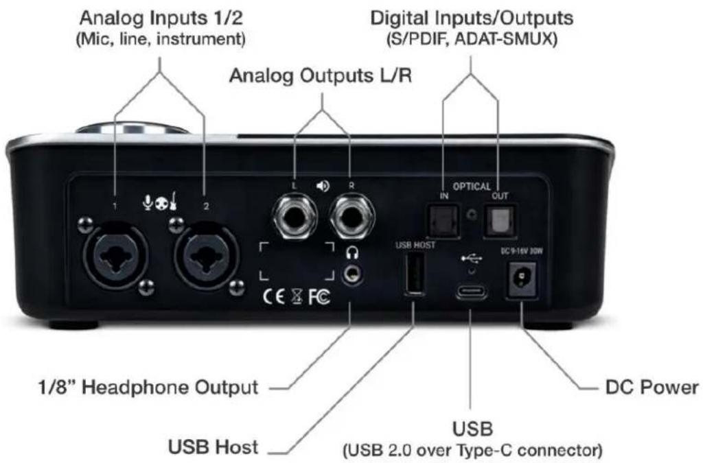
Symphony Desktop Panel Tour

Getting Started
Installing Apogee Desktop Software
To register your product and receive the Symphony Desktop Installer, learn the most up-to-date information on new releases, and view Interactive tutorials, click the link below.
www.apogeedigital.com/support/symphonydesktop
Once you've registered your Symphony Desktop, you'll receive an email with links to Mac and Windows versions of the Symphony Desktop Installer download.
macOS Installer
Once downloaded, double-click the .dmg file to display the contents:
- Desktop Control Software Installer
- SymphonyDesktopUpdate file
- Documentation for Symphony Desktop & Apogee plugins
- Symphony Desktop Uninstaller
To install Desktop Control Software:
- Double-click the Desktop Control Software installer.
- A dialog box will appear with a series of steps to complete the installation.
- By default, all Apogee plugins are installed in all formats. Even if you don't have an iLok license for a plugin, you can try it for a limited time. You can customize what plugins and formats are installed in the Plugins step.
- You will be required to restart your computer.
Windows 10 Installer
- In your Downloads folder, double-click the .zip file to extract it, then double-click the .exe file to start the installation process.
- By default, all Apogee plugins and documentation are installed, In the Select Components window, you can de-select plugins and/or plugin formats you don't want to install.

Setup - Symphony Desktop version 1.0.0


Select Components
Which components should be installed?

Select the components you want to install clear the components you do not want to install. Click Next when you are ready to continue.

Current selection requires at least 481.9 MB of disk space.
Next >
Cancel
- Click Next through all steps, then click Finish at the final step.
- You should restart your computer immediately.
- The User's Guides are installed on your computer's desktop.

iPad Pro/iPhone
There is no software to be installed when using Symphony Desktop with an iPad Pro or other iOS device like your iPhone. All Desktop settings are accessed from the touch screen.
Connecting Symphony Desktop
AC Power
- Connect the supplied Universal power supply to your AC (wall) outlet.
- For Type A-compatible outlets (North America) - Flip down the connector blades.
- For Type C, G or I-compatible outlets (UK, EU & SAA) - Slide the adaptor down over the closed connector blades.
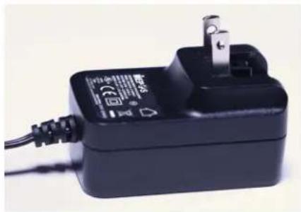
natural_image
Black rectangular electronic charger with charging cable and power plug (no visible text or symbols)
natural_image
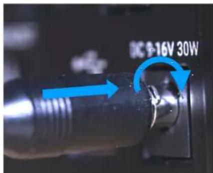
Close-up of a black electrical power adapter with attached plug and cable (no visible text or symbols)-
IMPORTANT, READ CAREFULLY- Symphony Desktop's DC connection includes a locking mechanism. Line up the locking tabs on the cable barrel connector with the locking slots on the rear panel DC socket.
-
Insert the barrel connector until it is flush against the socket, then turn clockwise until it stops.
-
Lightly tug the connector to ensure it's locked in place.
-
Tap the Control Knob to power up Symphony Desktop - the Apogee logo is displayed for approximately 30 seconds as the internal processor starts.
Connecting to a Mac or Windows computer
Using one of the supplied cables (USB-C to USB-C, or USB-C to USB-A), connect Symphony Desktop's USB-C port to a USB port on your Mac or Windows computer.
Be sure to use Symphony Desktop's USB-C port, not the port labelled USB Host.

Connecting to an iPad Pro (USB-C)
Using the supplied USB-C to USB-C, connect Symphony Desktop's USB-C port to the iPad Pro's USB-C connector.
Connecting to an iOS Device
Using one of the supplied cables (USB-C to USB-C or USB-C to USB-A), connect Symphony Desktop's USB-C port to an Apple Camera Connection Kit, supplied separately. The Camera kit's Lightning connector is then connected to your iOS device.

flowchart
graph TD
    A["Mac/Windows Computer"] -->|USB-C to USB-A| B["iPad Pro"]
    A -->|USB-C to USB-C| C["Camera Connection Kit (supplied separately)"]
    D["iPhone"] -->|USB-C to USB-A| C
Update Touch Screen Control
Please note - Before using Symphony Desktop, it's necessary to update Touch Screen Control, using the supplied USB thumb drive. If you don't have the supplied thumb drive, any USB thumb drive formatted in the FAT32 format will work. See below for formatting instructions on Mac & Windows.
- Connect the supplied USB thumb drive to your computer. To connect to a USB-C port, use a USB-A to USB-C adapter.
- On macOS - Double-click the Symphony Desktop Installer to open it, then drag the SymphonyDesktopUpdate folder into the USB thumb drive.
- On Windows 10 - In your Downloads folder, double-click the SymphonyDesktopInstaller.zip to extract the contents, then drag the SymphonyDesktopUpdate folder into the USB thumb drive
-
Eject the thumb drive from your computer, then connect the thumb drive to the Symphony Desktop rear panel USB Host connector.
-
On the Symphony Desktop touch screen, tap the gear icon to open System Settings, then swipe right to page 3 (page 2 in early versions).
- Tap the Update (labelled Firmware in early versions) button, then tap Check for Update.
- Tap Yes to the Update? query, tap Yes again to the Proceed? query.

-
The Touch Screen Control update will start as indicated by a progress bar. Do NOT power Symphony Desktop off or remove the power connection.
-
Once the Touch Screen Control update is complete, Symphony Desktop will automatically power cycle. It is now ready for use.

To use your own USB thumb drive, it must be formatted to the FAT32 file system.
1. On macOS:
- Connect your USB drive to your computer, then open Disk Utility from the Applications > Utilities folder.
- In the menu bar, select View > Show All Devices.
- In the left hand External column, click the USB thumb drive Root Device (i.e the volume representing the thumb drive that's higher and to the left).
- In the upper Toolbar, click the Erase button.
- Enter a name, set the Format to MS-DOS (FAT), set the Scheme to Master Boot Record, then click Erase.

2. On Windows 10:
- Open File Explorer.
- Right-click on the USB thumb drive and choose Format.
- Set File System to FAT32 and click Start.

Configure OS to use Symphony Desktop for Audio I/O
macOS
To choose Symphony Desktop as the audio interface for Mac applications that don't have specific audio hardware preferences, such as Safari, Spotify, Voice Memos and others:
- Open System Preferences by choosing Apple menu > System Preferences.
- Click the Sound icon to open the Sound preferences panel.
- Click the Output tab, then click on Symphony Desktop in the devices list.
- Click the Input tab, then click on Symphony Desktop in the devices list.

Windows 10
To choose Symphony Desktop as the audio interface for Windows applications that don't have specific audio hardware preferences, such as Google Chrome, Spotify, and others:
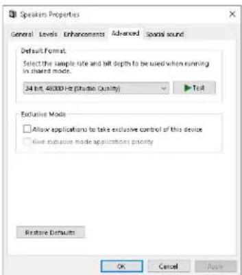
- Type Control Panel in the Windows search bar to open the Control Panel. Double-click the Sound icon.
- Click the Playback tab and select Speakers-Symphony Desktop.
- Click Properties, then click the Advanced tab.
- Uncheck Exclusive Mode checkboxes. When using a DAW and apps like Spotify simultaneously, match the Default Format sample rate with the rate of the DAW session.
- Click Apply.
- Click the Recording tab and repeat steps 2-5

Apple iOS
Apple iOS automatically chooses the most recently connected audio interface as the audio I/O device for all applications. Simply connect Symphony Desktop to your iOS device's Lightning or USB-C port as described here.
How to Reset Symphony Desktop

Symphony Desktop may be reset to its Default factory state from the Touch screen:
- Disconnect Symphony Desktop's USB connection from your computer.
- From the Touch screen Input/Output view, tap the System Settings gear icon.
- Swipe to page 3 of 3 on the Touch screen
- Tap Reset, then Yes.
- Symphony Desktop will reset to its factory default setting.
Connecting Your Studio
A wide range of devices, including dynamic & condenser microphones, electric instruments, speakers, headphones, and digital I/O expanders may be connected to Symphony Desktop.

-
Connect microphones and line level audio gear to the rear panel XLR inputs.
-
Connect dynamic and condenser mics to XLR inputs, then set Analog Level to Mic from the touch screen (link) or Desktop Control (link). When using condenser mics, be sure to engage 48v phantom power.
-
Connect analog line level audio gear line outputs to the XLR inputs using the appropriate adaptor if required. Set Analog Level to +4 dBu for professional sources, set to -10dBV for consumer level sources.
-
Connect synthesizers and keyboards to the rear panel 14 " inputs 1 & 2, then set Analog Level to Instrument from the touch screen or Desktop Control.
-
Connect consumer headphones, earbuds and balanced armature headphones (with comparatively low impedance and higher sensitivity) to the rear panel 18 " headphone output.
- Connect Main outputs 1-2 directly to active speakers. If your speakers are equipped with XLR inputs, use a 14 TRS (tip-ring-sleeve) to XLR male adaptor cable. If using passive speakers, connect the Main outputs to the speaker's amplifier inputs.
- Connect to your Mac, Windows or iOS device to the USB-C port.

- Connect electric guitars and basses to the front panel 14 input. Once the 14 connector is inserted, Input 2 Analog Level automatically toggles to Instrument.
Important Note - When connections are made to both the rear panel analog input 2 (XLR or TRS) and the front panel Instrument input, the rear panel connection takes precedence. To use the front panel instrument input, disconnect the rear panel connection.
- Connect professional headphones (with a comparatively higher impedance and lower sensitivity) to the front panel 14 " headphone output.

- Connect audio gear equipped with optical outputs only (such as mic preamp expanders, CD players, and other hi-fi devices) to the rear panel Optical input. Thanks to transparent sample rate conversion on the optical input, there's no need to clock one device to the other - both may remain set to Internal clock.
- Set Symphony Desktop Optical format to match that of the connected device from the touch screen (link) or Desktop Control (link).

-
For bi-directional streaming of digital audio between Symphony Desktop and Symphony IO MkII, interconnect Optical I/O between each interface.
-
Set Symphony Desktop and Symphony I/O MkII Optical format to ADAT or SMUX (depending on sample rate).
- Set Symphony I/O MkII Clock source to Optical.
TFT Touch Screen Control
The immersive Touch Screen Control and responsive Control knob gives you total control over all aspects of Symphony Desktop, from input and output levels, mic preamp emulation, Channel FX, and Direct monitoring mixers and routing.
Navigating the Touch screen Interface
The touch screen interface consists of four primary views - Input/Output (I/O), Optical, Mixer, and System Settings, accessible by tapping the icons indicated below. Once a primary view is selected, additional settings are accessed by tapping displayed buttons and swiping left <> right between views.

flowchart
graph TD
    A["Optical In View"] --> B["IN1"]
    C["I/O View"] --> D["IN2"]
    E["Mixer View"] --> F["OUT"]
    G["OPTICAL IN"] --> H["HP1"]
    I["OPTICAL OUT"] --> J["HP2"]
    K["System Settings"] --> L["FX FX"]
    M["44.10"] --> N["2"]
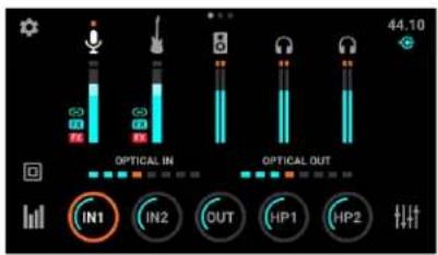
The Input/Output (I/O) view provides I/O metering, sample rate indication, connection status, and analog I/O parameters.
- The five circular I/O buttons at the bottom of the I/O view display level settings for Symphony Desktop's analog inputs and outputs.
- To quickly modify level settings, tap an I/O button to highlight it with an orange focus ring - this assigns the Control knob to that button. Turn the Control knob to increase or decrease the level
- Tap the highlighted button repeatedly to toggle through Overview and Settings screens for the selected input/output and the I/O View. You can also swipe left <> right to navigate through the views.
I/O Home View

Input 1 Overview

Input 1 Settings
- In the upper right hand corner of the touch screen, the hardware sample rate and current USB connection status are displayed.
To navigate the Mixer view, tap the Mixer icon in the lower right hand corner.

- To toggle between Mixer 1 and Mixer 2, tap the Mixer icon repeatedly or swipe L<>R between the mixers.
- To access individual Analog, Optical, Playback and Master Out channels, tap the specific Channel Type button repeatedly to toggle through channels - for example, tap the Analog Channel button to toggle between Analog IN 1 and Analog IN Mixer channels. You can also swipe through the views.
The Optical In view provides access to the Optical Format setting and the Print FX/Monitor FX DSP processing on the 2, 4 or 8 Optical inputs (depending on format and sample rate).

bar
| Metric | Value | | ---------------- | ------ | | SAMPLE RATE | 44.10 | | OPTICAL FORMAT | ADAT | | PRINT FX RACK | FX | | MONITOR FX RACK | FX | | IN1 | | | IN2 | | | IN3 | | | IN4 | | | OPT IN 5-8 | |To navigate System Settings, tap the System Settings icon in the upper left hand corner, then swipe left <> right to navigate through the 3 System Settings views.
Note that the System Settings icon may not be visible in I/O or Mixer "sub" views.
See below for a more detailed description of each view.
I/O Views
I/O Home View
After power-up, the I/O Home view is always displayed on the touch screen. It offers a global picture of all input/output audio signals and quick access to the most important level settings.
Input 1 & 2 Overview
The Input 1 & 2 Overview varies in functionality as determined by the Preamp setting and GUI Style selection. The 3 Preamp settings are described individually below: SD-MP (Symphony Desktop), AP-66 and AP-57. See Apogee Alloy Mic Preamp Emulation for more information.
SD-MP (Symphony Desktop)
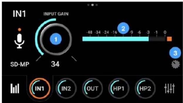
The SD-MP preamp is the cleanest of the 3 preamp options, with the incredibly wide gain range and clarity of Apogee's flagship Symphony I/O MkII.
- Input Gain - tap to set the gain of the preamp with the Control knob. Gain Control is hidden when Analog Level is set to +4dBu or -10 dBV line input.
- Digital meter - displays the digital level after A/D conversion
- Overview GUI - toggle the Overview GUI between TFT style and Channel FX style, as shown at right.

AP-66 Preamp
The AP-66 preamp is based on a vintage Neve 1066 mic preamp section with a gain range of 20-80 dB
- Input Gain - tap to set the gain of the preamp with the Control knob, when Analog Level is set to Mic or Instrument. Gain Control is hidden when Analog Level is set to +4dBu or -10 dBV line input.
- Digital meter - displays the digital level after A/D conversion
- Lo-Z Impedance - set the impedance of the mic preamp to low (300 ohms) when using low impedance mics, such as certain ribbon mics.
- Output level - tap to set the output level of the mic preamp stage.
- GL - Gain link - link the Input gain to the Output level so increasing the Input gain reduces the Output level to maintain a

consistent signal level. This is useful when driving the mic preamp emulation into distortion.
- Overview GUI - toggle the Overview GUI between TFT style and Channel FX style, as shown at right.

AP-57 Preamp
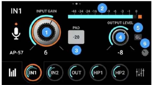
AP-57 - based on a highly modified Ampex tube mic preamp with a gain range of 0-10
- Input Gain - tap to set the gain of the preamp with the Control knob, when Analog Level is set to Mic or Instrument. Gain Control is hidden when Analog Level is set to +4dBu or -10 dBV line input.
- Digital meter - displays the digital level after A/D conversion
- Output level - (AP-66, AP-57 only) tap to set the output level of the mic preamp stage.
- GL - Gain link - (AP-66, AP-57 only) link the Input gain to the Output level so increasing
the Input gain reduces the Output level to maintain a consistent signal level. This is useful when driving the mic preamp emulation into distortion.
- -20 db Pad - (AP-57 only) decreases the sensitivity of the analog input by 20 dB. Engage the -20 dB pad when gain is set to 0 but the input is still overloading.

Input 1-2 Settings
-
Analog Level - choose the analog reference level for Analog inputs 1-2.
-
Choose Mic when connecting microphones or direct boxes to the XLR input.
- Choose Inst when connecting a guitar, keyboard, or any high impedance (Hi-Z) instrument to the 1/4" input (balanced TRS or unbalanced TS).
- Choose +4dBu when connecting "pro" gear with a nominal +4 dBu output level (such as an external mic pre, compressor, or EQ) to the XLR input.
-
Choose -10dBV when connecting “semi-pro”, hi-fi, or musical instrument gear with a nominal -10dBV dBu output level to the XLR input.
-
Preamp - jump to the Channel FX Preamp tab to select the mic preamp:
-
SD-MP - Symphony mic pre with no emulation processing and a gain range of 0-75 dB.
- AP-66 - based on a vintage Neve 1066 mic preamp section with a gain range of 20-80 dB.
-
AP-57 - based on a highly modified Ampex tube mic preamp with a gain range of 0-10.
-
Print FX Rack - Tap the On/Off button to toggle Print FX on/off. Tap the Print FX Rack button to open the Channel FX Print view.
- Monitor FX Rack - Tap the On/Off button to toggle Monitor FX on/off. Tap the Monitor FX Rack button to open the Channel FX Monitor FX view.
-
Input Settings
-
48V - enable 48 volt phantom power on each analog input when Analog Level is set to Mic. Most condenser mics require 48 volt phantom power to operate.
- Group - Link the Input Gain (plus Output Level and Gain Link button when present) of each analog input. Any level offsets that exists before inputs are grouped will be preserved after a group is chosen.
- Soft Limit - engage Soft Limit on each analog input. Soft Limit is an analog circuit that begins to attenuate transient peaks at a threshold of -4dBfs, replicating the transient softening of analog tape.
- Polarity Invert - invert the polarity of the analog input signal.
Apogee Channel FX
The Apogee Channel FX plugin is the key to Symphony Desktop's innovative workflows:
- Apply Apogee hardware and native DSP processing at all points of your overdubbing signal chain.
- Control Apogee hardware and native DSP processing from your DAW, Apogee Control 2 software and the Desktop touch screen.
To access the Channel FX from the touch screen, tap the Preamp, Print FX Rack or Monitor FX Rack buttons; the Channel FX view opens to the corresponding tab.
See Apogee Channel FX Rack for more information.

Apogee FX Plugins on the Touch Screen
Instantiate and control up to four Apogee FX plugins from the Print FX or Monitor FX views. Plugins may also be instantiated and controlled from the Channel FX plugin in your DAW and in Apogee Control 2 software, as described here.
Plugin settings may be modified on the touchscreen as shown in the example below. Basic operation of each plugin is described below. See the Apogee FX User's Guide for descriptions of each plugin's settings.
- Settings for the Symphony ECS Channel Strip are displayed across two views. To toggle between the two views, tap the Up & Down arrows or swipe up/down.
- To adjust parameter settings, tap the control to highlight it with an orange highlight - this assigns the Control knob to that setting. Turn the Control knob to change the setting. a. Double-tap rotary controls to return them to their default setting.
- To toggle buttons, tap them directly on the touch screen.
- Tap the "X" to close the interface and return to the Print FX or Monitor FX tab.


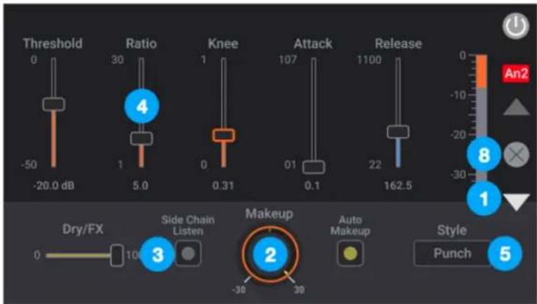
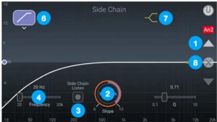
- Settings for the ModComp Visual Compressor/Limiter are displayed across two views. To toggle between the two views, tap the Up & Down arrows or swipe up/down.
- To adjust parameter settings, tap the control to highlight it with an orange highlight - this assigns the Control knob to that setting. Turn the Control knob to change the setting. a. Double-tap rotary controls to return them to their default setting.
- To toggle buttons, tap them directly on the touch screen.
- To adjust sliders, tap them, then turn the Control knob to change the setting.
- To select Style, tap the Style button, then select from the popup.
- In the Side Chain view - To engage, solo or modify the High Pass filter, tap the High Pass button, then tap the desired function.
- In the Side Chain view - To engage, solo or modify the Peak/High Shelf band, tap the Peak/HighShelf button, then tap the desired function.
- Tap the "X" to close the interface and return to the Print FX or Monitor FX tab.
The Mod EQ 6 Parametric EQ is displayed in a single touchscreen view.
-
To adjust parameter settings, tap the control to highlight it with an orange highlight - this assigns the Control knob to that setting. Turn the Control knob to change the setting. a. Double-tap rotary controls to return them to their default setting.
-
To adjust sliders, tap them, then turn the Control knob to change the setting.
-
To engage, solo or modify each of the 6 EQ bands, tap the Band button, then tap the desired function.
-
Tap the "X" to close the interface and return to the Print FX or Monitor FX tab.

line
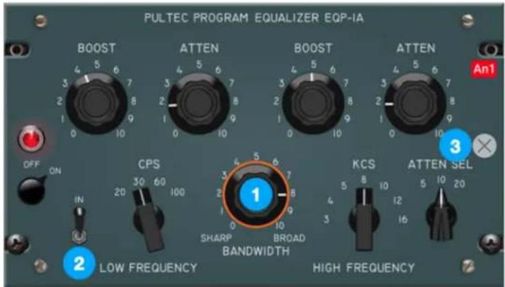
| Frequency | Gain | | --------- | ---- | | -24 | -24 | | 20 | 24 |The Pultec EQP-1A, Pultec MEQ-5, and Opto-3A are each displayed in a single touchscreen view.
- To adjust settings, tap the rotary knob or switch to highlight it with an orange focus ring - this assigns the Control knob to that control. Turn the Control knob to change the setting.
a. Double-tap rotary controls to return them to their default setting.
-
To toggle buttons, tap them directly on the touch screen.
-
Tap the "X" to close the window.


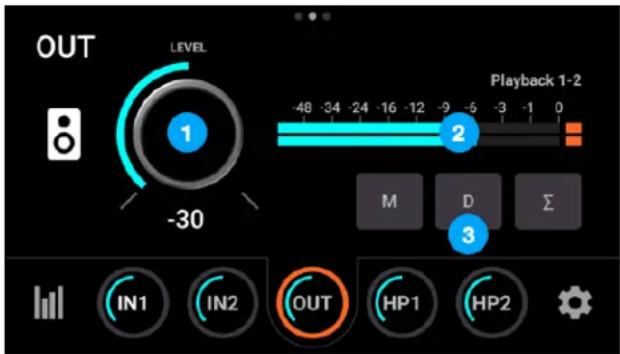
Main Out Overview
- Level - set the level of Main outputs 1-2;
- Source Meter - displays the digital level of the Main output source, before D/A conversion;
-
Main Out parameters:
-
Mute - mute the Main outputs 1-2.
- Dim - dim (reduce) the Main output 1-2 level by 15 dB.
- Sum to Mono - sum to mono the Main outputs.
Main Out Settings
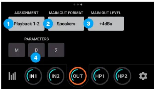
-
Assignment - choose the signal source for Main outputs 1-2;
-
SW Playback - route the selected stereo Playback signal from audio software to the Main output.
- Direct Mixers - route the stereo signal from the selected mixer to the Main output.
- HW:Inputs - route the selected mono or stereo signal from the selected hardware input(s) to the Main output.
-
Main Out Format - set the Main output format;
-
Variable - use the Control knob or software volume controls to modify the Main output level.
-
Fixed - the Main output level is fixed at the selected reference level.
-
Main Out Level - set the Main output reference level:
-
+4dBu - set the reference level to +4 dBu when connecting to professional gear.
-
-10 dBV - set the reference level to -10 dBV when connecting to consumer gear.
-
Main Out parameters:
-
Mute - mute the Main outputs 1-2.
- Dim - dim (reduce) the Main output 1-2 level by 15 dB.
- Sum to Mono - sum to mono the Main outputs.
Headphone Out 1-2 Overview
-
Level - displays the level of the headphone output:
-
HP1 = front panel output.
-
HP2 = rear panel output.
-
Source Meter - displays the digital level of the HP output source, before D/A conversion.
-
Main Out parameters:
-
Mute - mute the Main outputs 1-2.
- Dim - dim (reduce) the Main output 1-2 level by 15 dB.
- Sum to Mono - sum to mono the Main outputs.

Headphone Out 1-2 Settings
-
Assignment - choose the signal source for the headphone output;
-
Follow Main -
- SW:Playbacks - route the selected stereo Playback signal from audio software to the HP output.
- Direct:Mixers - route the stereo signal from the selected mixer to the HP output.
-
Direct: HW Inputs - route the selected mono or stereo signal from the selected hardware input(s) to the HP output.
-
HP 1-2 parameters:
-
Mute - mute the HP1 or HP2 outputs.
- Dim - dim (reduce) the HP1 or HP2 output level by 15 dB.
- Sum to Mono - sum to mono the HP1 or HP2 outputs.

Mixer Views
Mixer Overview

- Tap the Mixer icon repeatedly to toggle between the two Direct mixers. You can also swipe L<>R between the mixers.
- Tap repeatedly or swipe to toggle between Analog IN Channel settings views.
- Tap repeatedly or swipe to toggle between Optical IN Channel settings views.
- Tap repeatedly or swipe to toggle between Playback Channel settings views.
- Tap to display the Mixer Master settings view.
Channel Settings
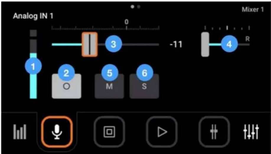
- Input meter (mono or stereo) - displays the digital signal level of the channel. The Analog IN channel levels are post A/D conversion.
- Stereo Link - tap to toggle the channel between mono and stereo. Playback channels are always stereo linked, so no button appears.
- Channel fader - Set the level of the channel signal in the Mixer Master stereo output.
- Channel pan control - Set the left-right placement of the channel signal in the Mixer Master stereo output. Stereo
- Mute - Mute the signal to the mixer stereo output.
- Solo - Solo the channel - all other channels are muted (unless their Solo button is engaged).
Optical Input Views
bar
| Category | Value | | -------------- | ------ | | OPTICAL IN 1 | -24 | | SAMPLE RATE | 44.10 | | OPTICAL FORMAT | ADAT | | PRINT FX RACK | FX | | MONITOR FX RACK| FX |-
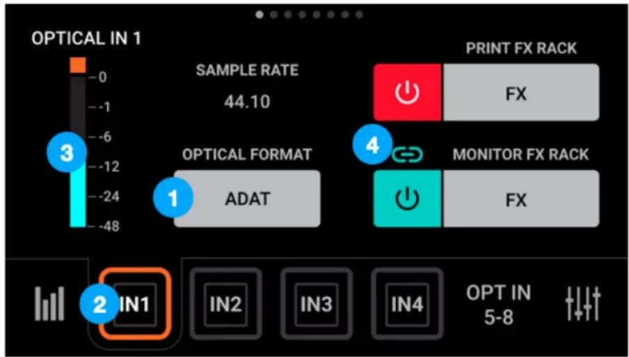
Optical Format - tap to set the Optical I/O digital format:
-
S/PDIF - 2 channel format at sample rates of 44.1-96kHz.
- ADAT - 8 channel format at sample rates of 44.1-48 kHz.
-
SMUX - 4 channel format at sample rates of 88.2-96kHz.
-
Tap IN1-IN4 to display Optical inputs 1-4; tap OPT IN 5-8 to collapse IN1-4 and display Input 5-8 buttons.
-
This meter displays the input level from 0 to -48 dBfs.
-
Print/Monitor FX Rack - Tap the On/Off button to toggle Print/Monitor FX Rack on/off. Tap the Print/Monitor FX button to open the Print/Monitor FX Rack view.
System Settings Views
Page 1 - Routing
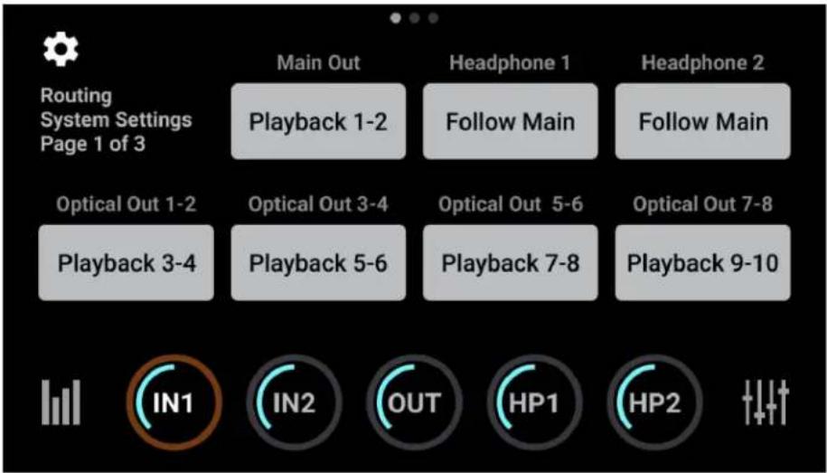
To configure routing for each stereo analog and digital output pair:
Tap an output button, then choose a source from the nested menu.
- SW:Playbacks - route the selected stereo Playback signal from audio software to the output.
- Direct:Mixers - route the stereo signal from the selected mixer to the output.
- Direct: HW Inputs - route the selected mono or stereo signal from the selected hardware input(s) to the output.
- Follow Main - Headphone 1 & 2 Output
only - when a headphone output is set to Follow Main, the audio signal routed to that output is determined by the Main Out Routing setting.

For example, to route the Direct Mixer 1 to the Main Out and Headphone 1 while routing Playback 3-4 to Headphone 2:
- Tap Headphone 1, then tap Follow.
- Tap Main Out, then tap Direct:Mixers > Mixer 1.
- Tap Headphone 2, then tap SW:Playbacks > Playback 3-4.
Page 2

- Optical Meters - tap to show or hide Optical I/O level meters on the I/O View.
-
Optical Format - tap to set the Optical I/O digital format:
-
S/PDIF - 2 channel format at sample rates of 44.1-96kHz.
- ADAT - 8 channel format at sample rates of 44.1-48 kHz.
-
SMUX - 4 channel format at sample rates of 88.2-96kHz.
-
Controller - set the behavior of the top panel Control knob when tapped:
-
None - nothing happens when tapping the Control knob.
- Mute All Outs - mutes the Main, HP1 and HP2 outputs.
- Mute Main Outs - mutes the Main outputs only.
- Mute HP1 - mutes the front headphone output only.
- Mute HP2 - mutes the rear headphone output only.
- Toggle Mute HP/Speaker - toggle between Main outs muted/headphones unmuted and Main outs unmuted and headphone muted. Great when you're tracking in the control room and want to listen to playback over speakers.
-
Toggle I/O Selections - Toggle the Control knob assignment through the two inputs and three outputs.
-
Peak Hold - tap to set the time* that peak indicators are held on the level meters.
-
Over Hold - tap to set the time* that over indicators are held on the level meters.
Page 3

- Sleep Timer - tap to set the time that, if untouched, the touch screen enters sleep mode.
- Display Brightness - set the brightness of the touch screen.
-
Sample Rate
-
When Symphony Desktop is connected to a computer or iPad, the sample rate is a read-only indicator of the current sample rate.
-
When Symphony Desktop is not connected, i.e. in Standalone mode, tap to set the system sample rate.
-
Update - Check and update Touch Screen Control.
- Reset - Reset Symphony Desktop to its factory default state.
Shutdown/Display Sleep
To power off Symphony Desktop, tap and hold the Control knob.
- Tap Display Sleep to turn off the touch screen but maintain full audio and Control knob operation.
- Tap Shutdown to power off Symphony Desktop.
Apogee Control 2 Software
The Apogee Desktop Control application provides access to all settings, including System setup, direct monitor mixing, hardware DSP and Monitor controller functionality.
Note that since Apogee Control runs Apogee FX plugins, an iLok license must be activated to your computer's hard drive or to a connected iLok.
Primary Window
All features and settings of the Symphony Desktop interface can be controlled from the Primary window. It is broken down into the following sections:
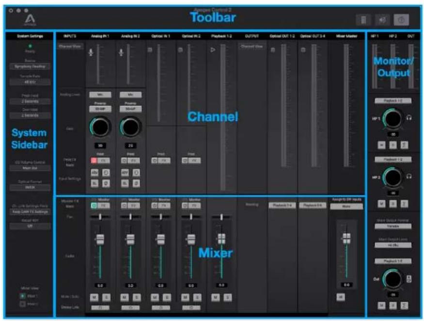
Tool Bar

- Show/hide System Settings sidebar
- Clear Meters
- Mute Outputs
- Open the Hover Help window
System Settings Sidebar
Provides System-wide settings that apply to your recording system as a whole.
-
System Status Display - Displays the status of the connected hardware.
-
Green - System is ready: Hardware is connected and recognized, and the digital clock is locked to the Clock Source.
-
Red - System not ready. Either the hardware is not connected, or the system is not locked to the Clock Source.
-
Device - When multiple Apogee hardware devices are connected to your computer, choose which device's settings are displayed in Apogee Control 2.
- Sample Rate - Set Symphony Desktop's sample rate. In some cases this setting may be overridden by software running on the computer (e.g. when a DAW session is open).
- Peak Hold - Set the time that peak indications are held on the level meters.
- Over Hold - Set the time that over indicators are held on the level meters.
- OS Volume Control - Choose the Symphony Desktop analog outputs to be controlled by the Mac System Preferences > Sound Output volume slider.
-
Optical Format - Set the digital audio protocol for the optical connectors. Match the optical format to that of the connecting device:
-
SPDIF: Optical I/O is formatted in the SPDIF format, which offers 2 channels at a sample rate up to 96kHz.
- ADAT/SMUX: Optical I/O is formatted in the ADAT/SMUX format, which offers 8 channels 44.1/48kHz sample rate and 4 channels at 88.2/96kHz.

- Channel Link Recall Preference - When a DAW Channel FX plugin is linked to hardware Channel FX using the Channel Link setting, this preference determines which Monitor FX Settings are kept after linking. This includes the case when a DAW session with a previously linked Channel FX plugin is recalled.
- Always Ask - Display a dialog each time a Channel Link is established to determine which Channel FX settings to keep - Monitor FX settings from the DAW or Monitor FX setting from the Apogee hardware.
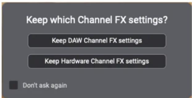
- Keep DAW FX Settings - when a Channel Link is established, always keep DAW Monitor FX settings. This is the default setting. In most cases, you'll want to keep the Monitor FX setting saved in your DAW session.
- Keep Hardware FX Settings - when a Channel Link is established, always keep Apogee hardware Monitor FX settings.
- Don't ask again - when checked, this dialog is no longer displayed. It's always possible to set the preference back to Always Ask. If Symphony Desktop is reset, this preference is reset to Always Ask.
Note that the Print FX tab is never saved in the DAW session - it always displays the current state of the hardware Print FX.
- Recall 48v - This setting determines whether 48 volt phantom power is recalled with other Input settings like Input source and gain. Set to Off to avoid unintentionally applying 48 volt phantom power to Desktop's XLR inputs. Set to On if you're confident that no device connected to the XLR connectors will be harmed by 48 volt phantom power.
- Mixer View - Show/hide the Direct mixers in the Primary window.
Channel Section
This portion of the Primary window displays channels for Analog input, Optical input, Playback input, and Optical output.
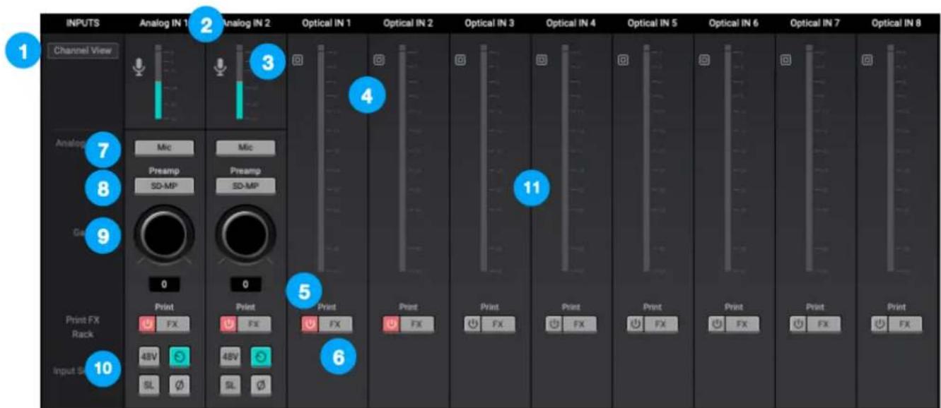
General Settings
- Channel View Button - click to open the Input Display Window, to show/hide Analog, Optical and Playback inputs.
- Channel Label - Indicates the channel type - Analog In, Optical In Playback, or Optical Out. Analog and Optical IN labels are transmitted to your DAW.
- Channel Icon - Displays the channel type. Analog IN icons display the input type selected from the Analog Level drop-down.
- Input Channel Level Meter - displays the digital signal level of the channel. The Analog IN channel levels are post A/D conversion.
- Print FX On/Off - Toggle on/off Apogee Channel FX plugins on the Print signal path.
-
Load Print FX - Load and modify Apogee Channel FX plugins on the Print signal path. See Apogee Channel FX Rack for more information about Print and Monitor FX.
-
Analog Level - choose the analog reference level for Analog inputs 1-2.
-
Choose Mic when connecting microphones or direct boxes to the XLR input.
- Choose Inst when connecting a guitar or keyboard, or any high impedance (Hi-Z) instrument to the 1/4" input (balanced TRS or unbalanced TS).
- Choose +4dBu when connecting “pro” gear with a nominal +4 dBu output level (such as an external mic pre, compressor, or EQ) to the XLR input.
-
Choose -10dBV when connecting “semi-pro”, hi-fi, or musical instrument gear with a nominal -10dBV dBu output level to the XLR input.
-
Preamp - Choose a Mic preamp
-
SD-MP - Symphony mic pre with no emulation processing and a gain range of 0-75 dB.
- AP-66 - based on a vintage Neve 1066 mic preamp section with a gain range of 20-80 dB.
-
AP-57 - based on a highly modified Ampex tube mic preamp with a gain range of 0-10.
-
Gain Control - Adjust the gain of the preamp. Gain Control is hidden when Analog Level is set to +4dBu or -10 dBV line input.
-
Input Settings - Provides options for the various inputs:
-
48V - Enable 48 volt phantom power on the corresponding Analog In channel. Visible only when Analog Level is set to Mic. Most condenser mics require 48 volt phantom power to operate.
- Group - Link the Gain Controls (plus Output Level and Gain Link button when present) for each Analog In channel. Visible only when Analog Level is set to Mic or Instrument. Gain offsets that exist before grouping channels are preserved.
- Soft Limit - engage Soft Limit on each analog input. Soft Limit is an analog circuit that begins to attenuate transient peaks at a threshold of -4dBfs, replicating the transient softening of analog tape.
- Polarity Invert - Invert the polarity of the analog input signal. When a single sound source is picked up with 2 transducers, inverting the polarity of one transducer results in a fuller sound. For example, if a drum is captured with a mic on each drumhead, inverting the polarity of one mic results in a fuller sound with more low end. The same principle applies when capturing an electric instrument with a miked amp and a direct injection feed.
Optical IN Channels
-
Optical IN channels represent digital inputs from external digital audio devices like standalone mic preamp expanders, digitally connected synths, and others.
-
Optical inputs are routed to software (DAW) inputs 3-10, depending on the Optical Format setting;
- Optical inputs are routed to direct monitoring Mixers 1 & 2;
- Optical inputs may be routed to Optical and Monitor outputs for Standalone operation.
Playback & Optical Output Channels

-
Playback channels represent the playback signal from your audio software (DAW) outputs.
-
Playback channels are routed to direct monitoring Mixers 1 & 2 for using when Direct monitoring.
- Playback channels may be selected as the source for Monitor outputs when software monitoring.
-
Playback channels may be selected as the source for Optical outputs.
-
Optical output channels represent digital outputs to be connected to external digital audio devices.
- Channel View Button - click to open the Optical Output Display Window, to show/hide Optical Outputs.
-
The audio source for the channel is selected in the Routing dropdown menu:
-
Playbacks - route the selected stereo Playback signal from audio software to the Optical output.
- Mixers - route the stereo signal from the selected mixer to the Optical output.
- HW Inputs - route the selected mono or stereo signal from the selected hardware input(s) to the Optical output.
Mixer Section
The mixer section provides two independent mixers for blending Analog, Optical and Playback inputs.
- Route mixer outputs to Main and headphone outputs for low latency direct monitoring while recording;
- Route mixer outputs directly to audio software inputs;
- Route mixer outputs to Optical for standalone mixing.

- Mixer View - toggle the faders, pan controls and Mute/Solo buttons between two independent mixers, Mixer 1 and Mixer 2.
- Enable Apogee FX processing in the Monitor path (through the Mixer).
- Load Monitor FX - Load and modify Channel FX plugins on the Monitor signal path. See Apogee Channel FX Rack for more information about Print and Monitor FX.
-
Channel Pan Control - Set the left-right placement of the channel signal in the mixer stereo output.
-
Option-click to reset the pan to center (0)
-
Option+Command-click to set all pans in that mixer to center (0).
-
Channel Fader - Set the level of the channel signal in the mixer stereo output.
- Option-click to reset the fader to 0dB.
- Channel Mute button - Mute the signal to the mixer stereo output.
- Command-click to mute all channels
-
Channel Solo button - Solo the channel - all other channels are muted (unless their Solo button is engaged).
-
Command-click to solo all channels.
-
Control-click the Solo button to engage Solo-Safe mode, where the channel remains unmuted regardless of the Solo status of other channels.
-
Assign to SW Inputs
- Assign the output of the Mixer to a stereo pair of software inputs. This overrides the default hardware input routing. See Mix Inputs before recording for more information.
- Mix Master Output Fader - Set the output level of the Mixer.
Monitor/Output Section
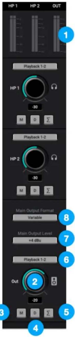
In the Monitor/Output Section, select the signals to be routed to the Main and Headphone outputs, then control their volume. Output Level Meters display the presence of signal at the outputs, useful as a diagnostic tool.
- Output Level Meters - Displays the level of the HP1, HP2 or Main outputs' digital source.
The following settings are available for the Main, HP1 and HP2 outputs:
- Output Level Control - Set the listening level of the output.
- Mute - mute the output
- Dim - dim (reduce) the output by 15 dB;
- Sum to Mono - Collapse left and right signals to mono at the output. This combined signal is sent through both Left and Right Outputs and is useful for verifying the mono-compatibility of a stereo mix.
-
Source - choose the signal source for the output (Main, HP1 or HP2).
-
SW Playback - route the selected stereo Playback signal from audio software to the HP output.
- Direct Mixers - route the stereo signal from the selected mixer to the HP output.
- HW:Inputs - route the selected mono or stereo signal from the selected hardware input(s) to the HP output.
These settings are only available for the Main Output:
-
Main Output Format - Select the format of the Main 14 " analog outputs:
-
Variable - Choose Variable when connecting directly to powered monitors or a power amplifier connected to passive speakers. Output level may be set using the Control knob.
-
Fixed - Choose Fixed when connecting to devices that include level controls, such as mixing consoles.
-
Main Output Level - Select the line-level reference for the Main output jacks:
-
Choose +4dBu when connecting to "pro" gear with inputs at a +4dBu nominal level.
- Choose -10dBV when connecting to "semi-pro", hi-fi, or musical instrument gear with inputs at a -10dBV nominal level.
Menu Bar Menus

Preferences - Choose this menu item to display hardware and software version information and change the Share Diagnostic Information preference.
Hide Apogee Control 2 - Choose this menu item to hide the Apogee Control 2 application.
Hide Others - Choose this menu item to hide all other open applications.
Show All - If any open applications have been hidden, choose this menu item to reveal all open applications.
Quit Apogee Control 2 - Choose this menu item to quit Apogee Control 2.
Apogee Alloy Mic Preamp Emulation
Getting Started with the AP-66

The AP-66 is modeled after a vintage Neve 1066 with the “round-can” Marinair input transformer. Does this version of the input transformer sound “better” than the later rectangular version in the 1073? We’re not making any claims here, but we tried a few different modules (1066s, 1073s) and we chose this one to model.
When you first open the AP-66, the Input Gain and Output level are set so you'll experience some saturation with many typical input sources. Raise the Input gain for more saturation, then adjust the Output level for a proper recording level.
Here's a way to easily experience the entire range of our Neve emulation from subtle warming to full-on distortion while maintaining a relatively consistent output level:
- Choose the AP-66 mic preamp emulation on the touch screen by tapping the IN1 button until the Settings view is displayed.
- Tap Preamp, then choose AP-66, then tap the "X".
- Tap the IN1 button to display the Overview view.
- Set Output Level to 0.
- Input the signal to be recorded, and set Input Gain for a proper recording level. The meter should display an average level around -16 to -12 dBFs, with -6 dBFs peaks.
- Tap GL (Gain Link) - now, as the Input Gain is raised, the Output Level lowers to compensate.
- As you increase the Input Gain, you'll hear more and more saturation, then an overdriven sound, and finally very audible distortion. Experience to discover the effect that best suits your creation!
Getting Started with the AP-57
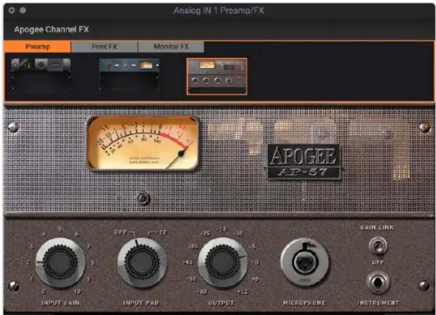
The AP-57 is modeled after a highly modified Ampex 601 tube preamp, part of a suitcase recording system from the late 1950s. The specific hardware unit used for modeling included the optional input transformer, a custom input attenuator and other custom tweaks.
Our AP-57 mic preamp emulation reproduces the complete experience using a 50s tube mic preamp - the larger-than-life sound, the rich harmonics, and the rapid onset of distortion, especially when using high-output large diaphragm condenser microphones!
If you have a 50s tube mic pre, you probably have an in-line attenuator or two just to be able to record with a condenser mic without overloading the mic pre input. Then again, if you're looking for a warm but present distortion, the 601 preamp gets you there quickly.
With our AP-57 emulation, you've got this choice as well - start with no pad, turn up the gain, and bask in the thick harmonics! If you're barely cracking the Input gain but getting too much, engage the -20 dB pad - you'll be able to increase the gain with less distortion.
Once you've determined the pad setting, tap GL (Gain Link) to couple the Input Gain and Output Level controls to work together. The AP-57 emulation offers more extreme sounds than the other mic preamp emulations, so approach it with a creative mindset!
Apogee Channel FX Rack
The Apogee Channel FX Rack is at the heart of what makes Symphony Desktop unlike any other audio interface available. Thanks to the Channel FX Rack's flexibility, Symphony Desktop can offer the wide array of innovative workflows described in Choose Your Symphony Desktop Workflows.
Specifically, the Channel FX Rack offers these unique features:
- The Channel FX Rack offers Apogee DSP processing, running on Apogee hardware DSP and natively on your computer's CPU, at several points in the typical overdubbing signal path.
Processing is organized in the Channel FX rack by the following tabs:
- Preamp tab - Apogee Alloy mic preamp emulation running on Apogee hardware DSP.
- PrintFX tab - Apogee FX plugins running on Apogee hardware DSP.
- MonitorFX tab - Linked Apogee FX plugins running both on Apogee hardware DSP and natively on your computer's CPU.

flowchart
graph TD
    A["User with headphones"] --> B["PREAMP"]
    B --> C["1"]
    C --> D["PRINT FX"]
    D --> E["2"]
    E --> F["MONITOR FX"]
    F --> G["3"]
    G --> H["MONITOR FX"]
    H --> I["3"]
    I --> J["Play back"]
    J --> K["Record"]
    style A fill:#f9f,stroke:#333
    style K fill:#ccf,stroke:#333
- The Channel FX Rack may be opened in your DAW, in Apogee Control software, or on the Symphony Desktop touch screen - you choose the workflow that's most convenient for you.


DAW Channel FX Apogee Control Channel FX Touch screen Channel FX
With the exclusive Channel Link functionality, all three locations may be synchronized to operate in parallel. Open the Channel FX rack in your DAW, link to a hardware input, and control everything from a single app window. You'll no longer need to toggle between multiple apps during your session.
Channel Link
To get started with Channel FX, the first step is to set Channel Link from a Channel FX plugin opened in your DAW:
- Open your DAW and create a mono track.
- Set the DAW track Input selection to the Symphony Desktop hardware input your mic or instrument is connected to.
- Open a mono Channel FX plugin, and set Channel Link to the sameDesktop hardware input as the DAW track Input. This links the DAW track to the hardware input.
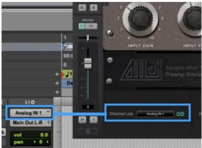
- If you're recording a stereo source like a keyboard, create a stereo DAW track, set the DAW track Input to the pair of Desktop inputs you've connected the keyboard to, open a stereo Channel FX plugin, and set Channel Link to the pair of hardware inputs used.
Now that Channel Link is set, all remaining settings (with a few exceptions noted below) are simultaneously available in the DAW plugin, in Apogee Control, and on Symphony Desktop's touch screen.
Rack Controls


- Direct Mixer Channel Strip (DAW Channel FX only) - When Channel Link is set to a hardware input, the corresponding Direct Mixer channel strip is displayed. This allows you to make hardware Input and Direct Mixer settings from your DAW window without toggling back to Apogee Control.
- Preamp, Print FX, Monitor FX tabs - display the Preamp, Print FX and Monitor FX tabs:
a. Preamp tab - Select Apogee Alloy mic preamp emulation and make settings. DSP processing is applied destructively (i.e. permanently) in the analog input circuitry and immediately after A/D conversion. All downstream signal path stages, such as the Direct Mixer channel and the recorded DAW audio, are permanently affected by mic preamp emulation.
b. Print FX tab - Open up to 4 Apogee FX plugins to process hardware inputs before routing to your DAW for recording. Like mic preamp emulation, all downstream signal path stages are permanently affected by Print FX processing.
c. Monitor FX tab - Open up to 4 Apogee FX plugins to process DAW playback (DAW Channel FX) or Apogee Control Mixer throughput (Apogee Control Channel FX). If you've set Channel Link in the DAW Channel FX, the Apogee Control Mixer Channel FX is automatically and transparently instantiated for DualPath monitoring.
- Channel Link Dropdown (DAW Channel FX only) - Set the Symphony Desktop hardware input to be linked to the DAW Channel FX plugin. See Channel Link for more details.
a. On the Apogee Control and Touch screen Channel FX Rack, a Channel Link indicator displays the state of the Channel Link: blue indicates connected, while grey indicates disconnected. - DSP Load Meter - displays the current percentage of hardware DSP in use over all Channel FX racks and channels. For more information about Symphony Desktop's DSP capabilities, see the DSP Plugin Instance Count chart.
- Rack IN & Rack OUT Trims & Meters - Trim the input and output levels of the Monitor FX rack as displayed by the In and Out meters.


The functionality of these settings varies based on the currently selected tab:
- Open Print FX or Monitor FX plugins - Click "+" to open up to 4 Apogee FX plugins. When multiple FX are opened, drag the FX icons to re-order them.
- Print FX or Monitor FX Presets - Open, save and toggle through Factory or User presets. Note that different presets may be loaded into the Print FX Rack and the Monitor FX Rack.
- Print FX or Monitor FX A >B - Toggle the current tab (Print FX or Monitor FX between two states, A and B.
- Copy to Print FX/MonitorFX - Copy the current configuration of plugins and settings from the Print FX tab to the Monitor FX tab or vice versa.
Using the Channel FX Plugin
The Channel FX plugin is conceived so you can run every aspect of your session from the DAW window. Once you've configured Apogee Control for software or Direct monitoring, you can minimize the window or close the app.
To get a better understanding of how to use the Channel FX plugin, let's step through a common recording situation - tracking lead, double, and background vocals.
In this example, you'd like to record the vocal with our AP-66 mic preamp emulation and a high pass filter that's printed on the recorded file, all while monitoring with a bit of high end boost and a touch of compression. With the Channel FX plugin, that's easy to set up and operate!
We'll assume that you've configured your DAW for use with Symphony Desktop, and you've configured Apogee Control for Direct monitoring through Analog In 1. See Configuring Your DAW for specific instructions. Also, you've connected your mic to Analog In 1 and headphones to Desktop's front headphone output.
In your DAW, open the Channel FX plugin and set Channel Link to Analog In 1. Now, Input 1 controls are displayed in the plugin, so you can turn on 48 volt phantom power, Soft Limit and other settings.

Click the Channel FX Preamp tab, then click the AP-66 icon. Now, set the Input gain and preamp output level - if you're using a condenser mic, start with an input gain of 30 dB and an output of -5 dB. Keep in mind that controls on the Preamp tab are in effect remote controls for the mic preamp emulation that run on Symphony Desktop hardware DSP. This processing is applied before the signal is sent to your DAW, so it's permanently recorded in your audio file.

Next, click the Channel FX Print FX tab, then click the "+" to add one instance of the Symphony ECS Channel Strip. Set the Hi Pass filter to 80 Hz - this setting removes any low end rumble that may be present in your recording space without removing any vocal frequencies. Like the Preamp tab, the Print FX tab is a remote control for plugins that run on Symphony Desktop hardware DSP. This processing is also applied beforethe signal is sent to your DAW, so it's also permanently recorded in your audio file.

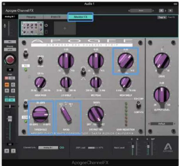
Finally, let's set up the Monitor FX tab with a bit of high end boost and some compression. Click the Monitor FX tab, then click the "+" to add an instance of ECS Channel Strip. Set the High Shelf for +4 dB of boost at 10kHz, then the Compressor Threshold to -10 and the Ratio to 3:1. Plugins on the DAW Channel FX's Monitor FX tab are running on your computer's CPU.
Apogee Symphony Desktop User's Guide
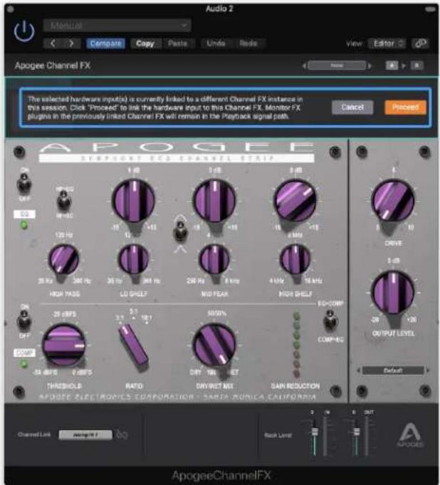
Once you've recorded your first track, you'll probably want to double it or record other vocal parts using the same settings you've carefully configured. The easiest way to do this is to duplicate the track in the DAW. When you open Channel FX on the new track, you'll see a dialog to transfer the Channel Link from the previous track to the current one - click Proceed.
After recording all your vocal tracks, save the session - you can pick right back up later with the exact same Monitor FX settings, and you can even open the session using Built-in audio hardware and listen to the tracks - all Monitor FX plugins remain active.

DAW Automation and Channel FX
Plugins running in the DAW Channel FX Monitor FX tab may be automated in your DAW. Automation parameters are dynamically added and removed to your DAW's automation parameters list as FX plugins are opened and closed.
For example, when one ECS plug is opened in the DAW Channel FX Monitor FX tab, ECS parameters with the prefix Monitor FX 0 appear in Pro Tools' Plugin Automation list.
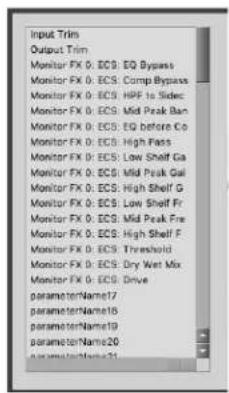
Add a second ECS, and parameters with the prefix Monitor FX 1 are added to the list. Likewise, when a third and forth plugin is opened, automation parameters with a prefix Monitor FX 2 and Monitor FX 3 are added to the list.

Plugins running in the PrintFX tab cannot be automated.
Channel FX On/Off Controls
Each On/Off control on the Channel FX plugin, including the DAW Bypass button, offers a specific function as described below.

-
DAW On/Off - the On/Off (or Bypass) button in your DAW plugin window affects plugins in the DAW Monitor FX tab only. Print FX plugins and linked Apogee Control (hardware DSP) plugins are not affected.
-
Print FX Tab On/Off - This button toggles all the plugins in the Print FX tab on/off.
-
Monitor FX Tab On/Off - This button toggles all the plugins in the Monitor FX tab on/off. If the Channel Link is set, then both DAW and Apogee Control (hardware DSP) Monitor FX plugins are affected.
-
Individual plugin On/Off - This button toggles each individual plugin in the Print FX and Monitor FX tabs on/off.
-
ECS On/Off - In the Symphony ECS Channel strip, the EQ and Compressor sections each have an On/Off toggle switch.
Channel FX Mono/Stereo Configuration
When linking Channel FX plugins in your DAW and in Apogee Control (hardware DSP), it's important to match the mono/stereo configuration of your DAW track and the Channel Link setting.
- If your DAW track is mono, the Channel FX plugin is mono as well - set Channel Link to one hardware input - Analog In 1 or Analog In 2.
-
If your DAW track is stereo, the Channel FX plugin may be stereo or dual mono.
-
If you select stereo, set Channel Link to a pair of hardware inputs;
- if you select dual mono, set the left settings window to one hardware input of a pair and the right settings to the other input.
- The Left-Right settings selection found in Logic Pro X is shown below; consult your DAW's documentation for more information.

Channel FX DSP Instance Count
The following chart indicates the number of Apogee FX plugins that may be opened simultaneously in the Print FX and Monitor FX tabs when the plugin is using hardware DSP.
- Print FX plugins always use hardware DSP
- Monitor FX plugins use hardware DSP when the Channel Link is set to a hardware input as described in the Monitor FX and Dualpath Monitoring section of this guide.
| Symphony ECS Mono | Symphony ECS Stereo | Pultec EQP-1A Mono | Pultec EQP-1A Stereo | Pultec MEQ-5 Mono | Pultec MEQ-5 Stereo | |
| 44.1-48 kHz | 14 | 7 | 48 | 24 | 48 | 24 |
| 88.2-96 kHz | 6 | 3 | 16 | 8 | 16 | 8 |
| 176.4-192 kHz | 2 | 1 | 8 | 4 | 10 | 4 |
Native instance count varies widely by computer make and models, but exceeds several hundred in most cases.
Choose Your Symphony Desktop Workflows
In the previous sections of this User's Guide, the individual components of Symphony Desktop have been described in detail. This section describes how these components work together to form a sophisticated and efficient audio production environment.
All of us - producers, engineers and artists - have their preferences when recording and mixing, so Symphony Desktop offers a wide variety of compelling workflow options.
When setting up your Desktop-based system, you have two workflow decisions to consider:
- Monitoring - how performers hear themselves while recording;
- DSP Signal Processing - how and where audio processing like mic preamp emulation, EQ and compression is applied.
With a better understanding of some important workflow concepts, you'll get the most from your Symphony Desktop.
To help you better understand the options available, the following glossary provides definitions of commonly used terms used in audio recording and processing:
A Glossary of Important Workflow Concepts
DAW (Audio Software) - The digital audio workstation, or DAW, is a specific type of audio software that offers sophisticated functionality, including the ability to choose an audio interface independently of the OS (operating system), manage multiple channels of input/output, support software or direct monitoring, support software plugins, and offers adjustable throughput latency.
Many software applications (Spotify, Youtube, for example) include audio input/output but don't offer the critical functionality for completely supporting Symphony Desktop workflows. Nevertheless, these apps can work with Symphony Desktop when the OS is configured to use Symphony Desktop for audio input/output, as described here.
Latency - If you've done any recording at all with your computer or iPad, you've probably encountered that annoying delay that makes recording your performance difficult - it's like you're trying to record over a transatlantic phone call - that's latency!
What is latency and why do you have to deal with it? Well, it starts with the fundamental process of digital audio - to convert audio waveforms to numbers for editing, processing, mixing and more, then convert numbers back into audio waveforms for listening. At each stage of your digital audio system - analog to digital conversion, recording & playback in your audio software, plugin processing - computations are performed on the digital audio that require time. Add up the total time from microphone input to headphone output, and the delay can significantly distract a performer as they record.
Buffer, aka IO Buffer, H/W Buffer - Most Digital Audio Workstation (DAW) software applications have a buffer setting, which is potentially the largest source of latency in your system. The buffer setting offers a range from 32 to 2048 samples* to specify the amount of time the app spends to pass audio from the hardware interface, record it, process it through plugins and mixing, and finally pass it back to the interface for listening. Why wouldn't you set the buffer to the lowest time, 32 samples? Then you'd get the lowest latency!
At the lowest setting, you're giving the DAW the least amount of processing time. As your session grows and you add tracks, plugins and virtual instruments, the DAW won't have enough time to complete the processing before the allotted time, and you'll get clicks, pops and other symptoms of a DAW application under stress.
* Buffer settings may vary by DAW and sample rate. Thus, the Buffer setting is always a compromise between lower latency and more processing power.

bar
| Category | Lower Latency | Higher Latency | | ---------------- | ------------- | -------------- | | Fewer Plugins | 32 | 64 | | More Plugins | 1024 | 512 | | Higher Latency | | 1024 | | Number of Plugins | 64 | 128 | | Number of Plugins | 128 | 256 | | Number of Plugins | 256 | 512 | | Number of Plugins | 512 | 1024 |Monitoring - One of the fundamental workflow choices you'll make is input monitoring - that is, how performers hear themselves while recording. Symphony Desktop offers two monitoring workflows, Software monitoring and Direct monitoring, which are described below in greater detail.
Native DSP Processing - When you open and run plugins in your DAW software, they use your computer's native CPU processing power to perform the required DSP, and are said to be native plugins. If you've set the DAW Buffer to it's maximum setting, you can run virtually thousands of Apogee plugins from a reasonably recent computer - there's really a lot of native DSP processing power available from your computer!
Hardware DSP Processing - Even though you can open thousands of plugins running natively on your computer, there are a few instances where you need hardware DSP processing on board your audio interface.
- To fulfill the requirements of Direct monitoring, your audio interface needs hardware DSP for the Direct monitoring mixer and plugins;
- Hardware DSP can process an interface input before it's sent to your DAW, so you can sculpt your sound and record the results.
Apogee Ensemble Thunderbolt, Element Series and Symphony Desktop all offer onboard hardware DSP.
Ideally, your plugins can run both as a native plugin in your DAW and as a hardware plugin in your audio interface's Direct monitoring mixer. The Apogee Channel FX plugin is one of the very few that can!
Apogee Channel FX Plugin - Apogee Channel FX is the collection of hardware and native DSP processing available in your Symphony Desktop-based audio production environment. The following unique capabilities of the Channel FX plugin unlock Desktop's innovative workflows:
- Runs both on Symphony Desktop hardware DSP and natively in your DAW
- Link Channel FX running natively in your DAW and on hardware DSP.
Apogee FX Plugins - the collection of Apogee plugins that can be opened in the Channel FX plugin:
- Pultec EQP-1A Program Equalizer
- Pultec MEQ-5 Midband Equalizer
- ModComp Visual Compressor/Limiter
- ModEQ 6 Parametric EQ
- Symphony ECS Channel Strip
- Opto-3A Compressor
Print FX - the term "Print FX" or "printing" is used in this guide to specify DSP processing that is "destructive", or permanently applied to the audio file being processed. For example, when EQ processing is "printed", it becomes a permanent and irreversible characteristic of the audio file.
Monitor FX - in contrast to Print FX, Monitor FX are on channel playback, and are thus "non-destructive" - you can always change your mind. As you become more confident with plugin processing, you may choose to print some effects while monitoring through others.
DualPath Monitoring - All of Symphony Desktop's innovative features work together to bring you the DualPath monitoring workflow, the easiest way to achieve direct monitoring with plugins all from your DAW window.
Monitoring Workflows
The first workflow choice you'll make concerns monitoring - software monitoring or direct monitoring.
Software Monitoring
When your system is set up for Software monitoring, the audio that the performer hears is routed through the DAW, including plugins and mixers, and thus incurs the maximum latency of the system, as shown below.

flowchart
graph LR
    A["SYMPHONY DESKTOP"] --> B["DAW"]
    B --> C["Record"]
    C --> D["Monitor"]
    D --> E["Play back"]
    E --> A
- Pros - This is the simplest monitoring workflow, where most settings are made in the DAW window.
- Cons - It's necessary to set the DAW IO Buffer setting to a compromise between lower latency and maximum CPU plugin processing - the lower the latency, the fewer native plugins may be run.
If you have a powerful computer and your sessions use a moderate amount of plugin processing, you may be able to find a Buffer setting that's low enough that latency isn't a problem but high enough that processing is completed without issues.
Direct Monitoring
Direct Monitoring, aka Low Latency Mixing - When the processing demands of your session require a higher Buffer setting that causes disruptive latency, Direct monitoring lets performers hear themselves through a separate mixer running on hardware DSP and controlled in Desktop Control software. The Direct mixer avoids the latency-inducing round trip through the DAW. To avoid double monitoring, the DAW must be configured so incoming audio to be recorded is NOT monitored through the DAW.
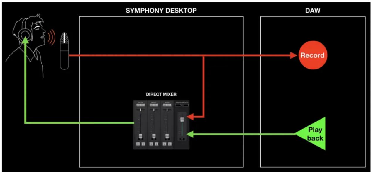
flowchart
graph TD
    A["SYMPHONY DESKTOP"] --> B["DAW"]
    B --> C["Record"]
    C --> D["Play back"]
    D --> E["DIRECT MIXER"]
    E --> F["Radio/Video/Audio Ratio"]
    F --> G["Radio/Video/Audio Ratio"]
    G --> H["Radio/Video/Audio Ratio"]
    H --> I["Radio/Video/Audio Ratio"]
    I --> J["Radio/Video/Audio Ratio"]
    J --> K["Radio/Video/Audio Ratio"]
    K --> L["Radio/Video/Audio Ratio"]
    L --> M["Radio/Video/Audio Ratio"]
    M --> N["Radio/Video/Audio Ratio"]
    N --> O["Radio/Video/Audio Ratio"]
    O --> P["Radio/Video/Audio Ratio"]
    P --> Q["Radio/Video/Audio Ratio"]
    Q --> R["Radio/Video/Audio Ratio"]
    R --> S["Radio/Video/Audio Ratio"]
    S --> T["Radio/Video/Audio Ratio"]
    T --> U["Radio/Video/Audio Ratio"]
    U --> V["Radio/Video/Audio Ratio"]
    V --> W["Radio/Video/Audio Ratio"]
    W --> X["Radio/Video/Audio Ratio"]
    X --> Y["Radio/Video/Audio Ratio"]
    Y --> Z["Radio/Video/Audio Ratio"]
    Z --> AA["Radio/Video/Audio Ratio"]
    AA --> AB["Radio/Video/Audio Ratio"]
    AB --> AC["Radio/Video/Audio Ratio"]
    AC --> AD["Radio/Video/Audio Ratio"]
    AD --> AE["Radio/Video/Audio Ratio"]
    AE --> AF["Radio/Video/Audio Ratio"]
    AF --> AG["Radio/Video/Audio Ratio"]
    AG --> AH["Radio/Video/Audio Ratio"]
    AH --> AI["Radio/Video/Audio Ratio"]
    AI --> AJ["Radio/Video/Audio Ratio"]
    AJ --> AK["Radio/Video/Audio Ratio"]
    AK --> AL["Radio/Video/Audio Ratio"]
    AL --> AM["Radio/Video/Audio Ratio"]
    AM --> AN["Radio/Video/Audio Ratio"]
    AN --> AO["Radio/Video/Audio Ratio"]
    AO --> AP["Radio/Video/Audio Ratio"]
    AP --> AQ["Radio/Video/Audio Ratio"]
    AQ --> AR["Radio/Video/Audio Ratio"]
    AR --> AS["Radio/Video/Audio Ratio"]
    AS --> AT["Radio/Video/Audio Ratio"]
    AT --> AU["Radio/Video/Audio Ratio"]
    AU --> AV["Radio/Video/Audio Ratio"]
    AV --> AW["Radio/Video/Audio Ratio"]
    AW --> AX["Radio/Video/Audio Ratio"]
    AX --> AY["Radio/Video/Audio Ratio"]
    AY --> AZ["Radio/Video/Audio Ratio"]
    AZ --> BA["Radio/Video/Audio Ratio"]
    BA --> BB["Radio/Video/Audio Ratio"]
    BB --> BC["Radio/Video/Audio Ratio"]
    BC --> BD["Radio/Video/Audio Ratio"]
    BD --> BE["Radio/Video/Audio Ratio"]
    BE --> BF["Radio/Video/Audio Ratio"]
    BF --> BG["Radio/Video/Audio Ratio"]
    BG --> BH["Radio/Video/Audio Ratio"]
    BH --> BI["Radio/Video/Audio Ratio"]
    BI --> BJ["Radio/Video/Audio Ratio"]
    BJ --> BK["Radio/Video/Audio Ratio"]
    BK --> BL["Radio/Video/Audio Ratio"]
    BL --> BM["Radio/Video/Audio Ratio"]
    BM --> BN["Radio/Video/Audio Ratio"]
    BN --> BO["Radio/Video/Audio Ratio"]
    BO --> BP["Radio/Video/Audio Ratio"]
    BP --> BQ["Radio/Video/Audio Ratio"]
    BQ --> BR["Radio/Video/Audio Ratio"]
    BR --> BS["Radio/Video/Audio Ratio"]
    BS --> BT["Radio/Video/Audio Ratio"]
    BT --> BU["Radio/Video/Audio Ratio"]
    BU --> BV["Radio/Video/Audio Ratio"]
    BV --> BW["Radio/Video/Audio Ratio"]
    BW --> BX["Radio/Video/Audio Ratio"]
    BX --> BY["Radio/Video/Audio Ratio"]
    BY --> BZ["Radio/Video/Audio Ratio"]
    BZ --> CA["Radio/Video/Audio Ratio"]
    CA --> CB["Radio/Video/Audio Ratio"]
    CB --> CC["Radio/Video/Audio Ratio"]
    CC --> CD["Radio/Video/Audio Ratio"]
    CD --> CE["Radio/Video/Audio Ratio"]
    CE --> CF["Radio/Video/Audio Ratio"]
    CF --> CG["Radio/Video/Audio Ratio"]
    CG --> CH["Radio/Video/Audio Ratio"]
    CH --> CI["Radio/Video/Audio Ratio"]
    CI --> CJ["Radio/Video/Audio Ratio"]
    CJ --> CK["Radio/Video/Audio Ratio"]
    CK --> CL["Radio/Video/Audio Ratio"]
    CL --> CM["Radio/Video/Audio Ratio"]
    CM --> CN["Radio/Video/Audio Ratio"]
    CN --> CO["Radio/Video/Audio Ratio"]
    CO --> CP["Radio/Video/Audio Ratio"]
    CP --> CQ["Radio/Video 100% Audio Signal"]
    CQ --> CR["Radio 100% Audio Signal"]
    CR --> CS["Radio 100% Audio Signal"]
    CS --> CT["Radio 100% Audio Signal"]
    CT --> CU["Radio 100% Audio Signal"]
    CU --> CV["Radio 100% Audio Signal"]
    CV --> CW["Radio 100% Audio Signal"]
- Pros - Low latency and maximum plugin power - the DAW IO Buffer may be set to its maximum value for the greatest number of native plugins without an effect on latency. Latency remains virtually non-existent through the direct monitoring mixer.
- Cons - With many audio interface systems, it's necessary to toggle between your DAW window and a separate direct monitoring mixer app. Adding non-destructive plugins while Direct monitoring can become unwieldy. Apogee's proprietary DualPath monitoring workflow, described here, addresses these disadvantages, so you benefit from the advantages without suffering the disadvantages.
DSP Processing Workflows
Symphony Desktop also includes flexible and powerful hardware and native DSP processing that supports a wide range of innovative workflows - 1) Apogee Alloy mic preamp emulation; 2) Print FX; 3) Monitor FX (DualPath Monitoring); and 4) Native operation.
DSP Processing workflows are independent of your monitoring workflow, with the exception of DualPath monitoring - Apogee's revolutionary approach to Direct monitoring with plugins.
Apogee Alloy Mic Preamp Emulation
Apogee Alloy mic preamp emulation employs circuitry found in Symphony Desktop's Analog inputs plus onboard hardware DSP to bring the warmth and character of classic mic preamps to your recordings.
The analog circuitry is a key component of the emulation processing, so mic pre emulation is available only on Analog In 1 & 2 mic, line and instrument inputs.
Mic preamp emulation is inserted into the signal path before the direct monitoring mixer and the "send" to your DAW, as shown below. Emulation processing is printed, i.e. it permanently modifies the audio signal, regardless of your monitoring workflow (Software or Direct monitoring). Of course, a hardware mic preamp would permanently change the audio as well!

flowchart
graph LR
    A["SYMPHONY DESKTOP"] --> B["DAW"]
    B --> C["Record"]
    C --> D["Play back"]
    D --> E["Direct Mixer"]
    E --> F["PREAMP"]
    F --> G["SYMPHONY DESKTOP"]
    style A fill:#f9f,stroke:#333
    style B fill:#ccf,stroke:#333
    style C fill:#cff,stroke:#333
    style D fill:#ffc,stroke:#333
    style E fill:#cfc,stroke:#333
    style F fill:#fcc,stroke:#333
    style G fill:#ffc,stroke:#333
To apply Alloy mic preamp emulation, open the Channel FX on the DAW channel(s) you're recording on. Set the Channel Link setting to match the DAW channel input setting as described here - now the Preamp, Print FX and Monitor FX tabs appear at the top of the plugin. Click Preamp and choose your preferred emulation.
Print FX
With Print FX, you can shape your sound as you record it using up to 4 Apogee FX EQ, compression and saturation plugins running on Symphony Desktop hardware DSP.
Print FX processing may be applied to Analog Inputs 1&2.
Print FX plugins are inserted in the signal path before the direct monitoring mixer and the "send" to your DAW, as shown below. Like mic preamp emulation, Print FX processing permanently modifies the audio signal regardless of your monitoring workflow (Software or Direct monitoring).

flowchart
graph TD
    A["Speaker with ear signal"] --> B["Print FX"]
    B --> C["Record"]
    C --> D["DAW"]
    D --> E["Play back"]
    E --> F["Direct Mixer"]
    F --> G["DAW"]
    style A fill:#f9f,stroke:#333
    style B fill:#ccf,stroke:#333
    style C fill:#cfc,stroke:#333
    style D fill:#fcc,stroke:#333
    style E fill:#cff,stroke:#333
    style F fill:#ffc,stroke:#333
    style G fill:#fcf,stroke:#333
To apply Print FX processing, open the Channel FX on the DAW channel(s) you're recording on. Set the Channel Link setting to match the DAW channel input setting as described here - now the Preamp, Print FX and Monitor FX tabs appear at the top of the plugin. Click the Print FX tab, then load up to 4 Apogee FX plugins.
Monitor FX & DualPath Monitoring
With Monitor FX and DualPath monitoring, users experience workflow benefits that have previously only been available with Avid Pro Tools HD - 1) very low latency, even when the DAW IO Buffer size is high 2) simple, non-destructive plugin workflow - open a single plugin in your DAW that processes monitoring and playback 3) control from a single app window - your DAW.
When you open Monitor FX plugins in a DAW Channel FX plugin and set Channel Link, the plugins are actually inserted in two different signal paths - 1) in the DAW Playback signal path and 2) before the direct monitoring mixer but after the "send" to your DAW, as shown below.
When recording, the performer hears himself through Monitor FX running on hardware DSP; playback, on the other hand, is heard through Monitor FX running natively in your DAW. Most importantly, the two plugins are control-linked, so settings made in one Channel FX plugin are mirrored to the other Channel FX plugin.
All this happens automatically and transparently when you open the Channel FX plugin in your DAW and link it to a hardware input. We call this revolutionary workflow DualPath Monitoring.
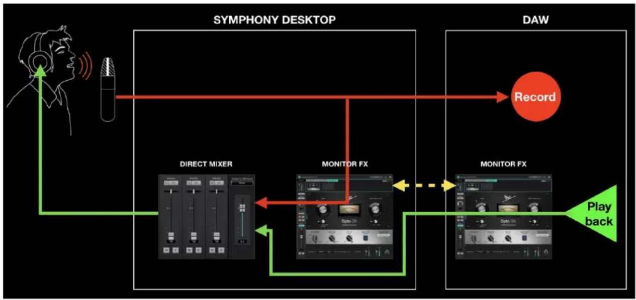
flowchart
graph TD
    A["SYMPHONY DESKTOP"] --> B["DAW"]
    B --> C["Record"]
    C --> D["MONITOR FX"]
    D --> E["Play back"]
    E --> F["MONITOR FX"]
    F --> G["Direct Mixer"]
    G --> H["Radio/Dem"]
    style A fill:#f9f,stroke:#333
    style B fill:#ccf,stroke:#333
    style C fill:#cff,stroke:#333
    style D fill:#ffc,stroke:#333
    style E fill:#cfc,stroke:#333
    style F fill:#fcc,stroke:#333
    style G fill:#fcf,stroke:#333
    style H fill:#cff,stroke:#333
Monitor FX & Software Monitoring
If you've configured your system for Software monitoring, you can still benefit from Monitor FX, even when Symphony Desktop isn't connected to your computer. Plugins opened in the Monitor FX tab in your DAW are powered natively by your computer's CPU, so they work even when you're using Built-In headphone outputs or other audio hardware.
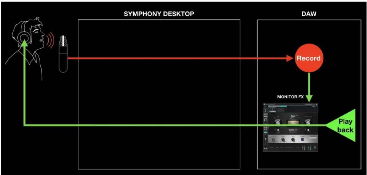
flowchart
graph LR
    A["SYMPHONY DESKTOP"] --> B["DAW"]
    B --> C["Record"]
    C --> D["MONITOR FX"]
    D --> E["Play back"]
Of course, all Apogee FX plugins may be run directly in your DAW, without opening them in the Channel FX plugin. These plugins are powered natively by your computer's CPU, so they work even when you're using Built-In headphone outputs or other audio hardware.
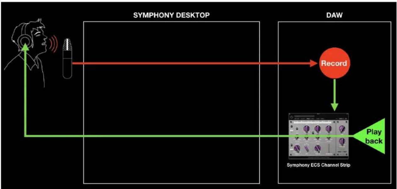
flowchart
graph LR
    A["Person with ear"] --> B["Mirror"]
    B --> C["Record"]
    C --> D["Play back"]
    D --> E["Symphony ECS Channel Strip"]
    style A fill:#f9f,stroke:#333
    style B fill:#ccf,stroke:#333
    style C fill:#cff,stroke:#333
    style D fill:#ffc,stroke:#333
    style E fill:#cfc,stroke:#333
Additional Workflows
Mix Inputs Before Recording
You can use the Symphony Desktop Mixer to mix hardware inputs and record the mixed output, using the Assign to SW (software) Inputs dropdown in the Apogee Control mixers. The possibilities include:
- Use two mics to capture an instrument and record a blend to one DAW track;
- Pan a single input to the center of a stereo output for audio apps without panning functionality.
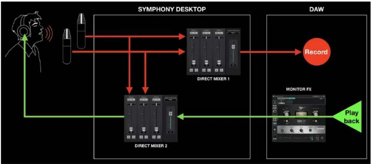
flowchart
graph TD
    A["SYMPHONY DESKTOP"] --> B["DIRECT MIXER 1"]
    A --> C["DIRECT MIXER 2"]
    B --> D["DAW"]
    C --> D
    D --> E["Record"]
    D --> F["MONITOR FX"]
    F --> G["Play back"]
In the workflow depicted above, set Direct Mixer 1 Assign to SW Inputs dropdown to Software Inputs 1-2. Now, the output of Mixer 1 is routed in place of Analog In 1-2 to your DAW's input.
Direct Mixer 2 is used for Direct monitoring, to mix hardware inputs with Playback outputs from the DAW. It looks complicated, but once configured it's pretty straightforward.
CAUTION - If Mixer 1 Playback inputs are active, you may create a feedback loop that results in a loud and potentially damaging oscillation. MUTE the Mixer's Playback inputs.
Configuring Your DAW
Find below detailed information to configure Symphony Desktop with popular DAWs:
- Configure the DAW to use Symphony Desktop
- Configure the DAW for Direct or Software monitoring
- Access Symphony Desktop inputs & outputs in the DAW
• Additional DAW-specific notes
Apple Logic Pro
To configure Apple Logic Pro to use Symphony Desktop:
- In the Logic Pro menu bar, choose Logic Pro > Preferences > Audio in the menu bar, then click the Device tab.
- Check the Core Audio checkbox; set Output Device and Input Device to Symphony Desktop.
- Set I/O Buffer Size to 128 or higher.
- Click Apply.

To configure Logic Pro for Direct or Software Monitoring Workflow:
- In the Logic Pro menu bar, choose Logic Pro > Preferences > Audio, then click the General tab.
- Check the Software Monitoring box to monitor through Logic while recording.
-
Leave the Software Monitoring box unchecked for Direct monitoring through the Apogee Control 2 low latency mixer.
-
In Apogee Control 2, set Main and Headphone Sources.
- Set to SW:Playbacks > Playback 1-2 for Software monitoring.
- Set to Direct Mixers: Mixer for Direct monitoring through the Apogee Control 2 mixer.
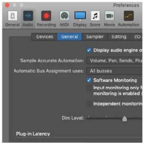
To access Symphony Desktop inputs & outputs in Logic Pro:
- From the Logic Pro menu bar, choose Mix > I/O Labels.
- Choose the Provided by Driver labels by clicking on the first label, dragging your mouse down until all Symphony Desktop labels are highlighted, then unclick.
- Close the I/O labels window.
- Select Symphony Desktop inputs and outputs in any Logic Pro Channel Strip.
Direct Monitoring with Apogee FX plugins - Logic Pro and Symphony Desktop:
For Symphony Desktop and Logic Pro, Direct monitoring with Apogee FX plugins is incredibly simple.
First turn off Logic's Software Monitoring in the Logic Preferences menu.
Then in the Apogee Control 2 software, make sure your output (HP and/or MAIN) are set to "Mixer 1".
- In a Logic audio track, select the desired Symphony Desktop Input(s) and Output.
- Instantiate the ApogeeChannelFX plugin on the Logic track.
- Engage the plugin's "Channel Link" to tie it to a Symphony Desktop input. This will cause the plugin to show the Control 2 mixer channel strip for that Symphony Desktop input.
- Use the fader slider to adjust the Direct monitoring level of the linked input channel.

Avid Pro Tools
To configure Avid Pro Tools to use Symphony Desktop:
- Open Pro Tools, then choose Setup > Playback Engine in the menu bar.
- Set Playback Engine to Symphony Desktop.
- Set H/W Buffer Size to 128 to start, adjust for lower latency or more plugin power.
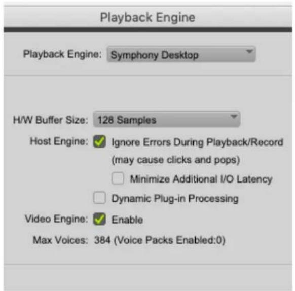
To configure Pro Tools for Direct or Software Monitoring Workflow:
- In the Pro Tools menu bar, set Options > Low Latency Monitoring.
- Uncheck Low Latency Monitoring for Software monitoring.
- Check Low Latency Monitoring for Direct monitoring.
- In Desktop Control, set Mixer View in the System Settings column.
- Set to Off for Software monitoring.
-
Set to On for Direct monitoring.
-
On the touch screen System Settings Page 1 or in Desktop Control, set Main and Headphone Sources.
- Set to Playback 1-2 for Software monitoring.
- Set to Mixer 1 for Direct monitoring.
To set channel Input & Output list labels:
- In the Pro Tools menu bar, choose Setup > I/O.
- In the IO Setup window, click the Input tab.
- Select all inputs in the Name column, then click Delete Path. Then, click Default to reset the Names to Desktop defaults.
- Repeat in the Output and Bus tabs.
Pro Tools Preference Setting
| Options Setup Window Avid Link | |
| Destructive Record | |
| Loop Record | ℃L |
| ✓ QuickPunch | ↑⌘P |
| TrackPunch | ↑⌘T |
| DestructivePunch | |
| Prepare DPE Tracks | |
| Transport Online | ⌘J |
| Video Track Online | ↑⌘J |
| Pre/Post-Roll | ⌘K |
| ✓ Loop Playback | ↑⌘L |
| Dynamic Transport | ^⌘P |
| Edit Window Scrolling | ▶ |
| ✓ Link Timeline and Edit Selection | |
| Link Track and Edit Selection Insertion Follows Playback | ↑T |
| Tab to Transient Mirrored MIDI Editing | ℃⌘→ |
| ✓ Automation Follows Edit Layered Editing | |
| ✓ Click | |
| ✓ MIDI Thru | |
| Auto-Spot Clips | ℃⌘P |
| ✓ Pre-Fader Metering Solo Mode | ▶ |
| Edit/Tool Mode Keyboard Lock | ^ ⌘T |
| ✓ Delay Compensation Activate HEAT | |
| Low Latency Monitoring | |
-
To use native reverb while Direct monitoring, choose Pro Tools > Preferences to open the Preferences window; click the Mixing tab, then check "Allow Sends to persist during LLM" under Setup.
-
When checked, Pro Tools channels behave in the following manner that's crucial to the DualPath workflow and other operations of the Channel FX plugin.
- When Record or Input is activated on the channel, the plugin interface remains active including level meters.
- Bus sends remain active, so the channel's input signal may be sent to native reverbs even though the channel's input is not routed to the session Master output (because Low Latency has been checked).
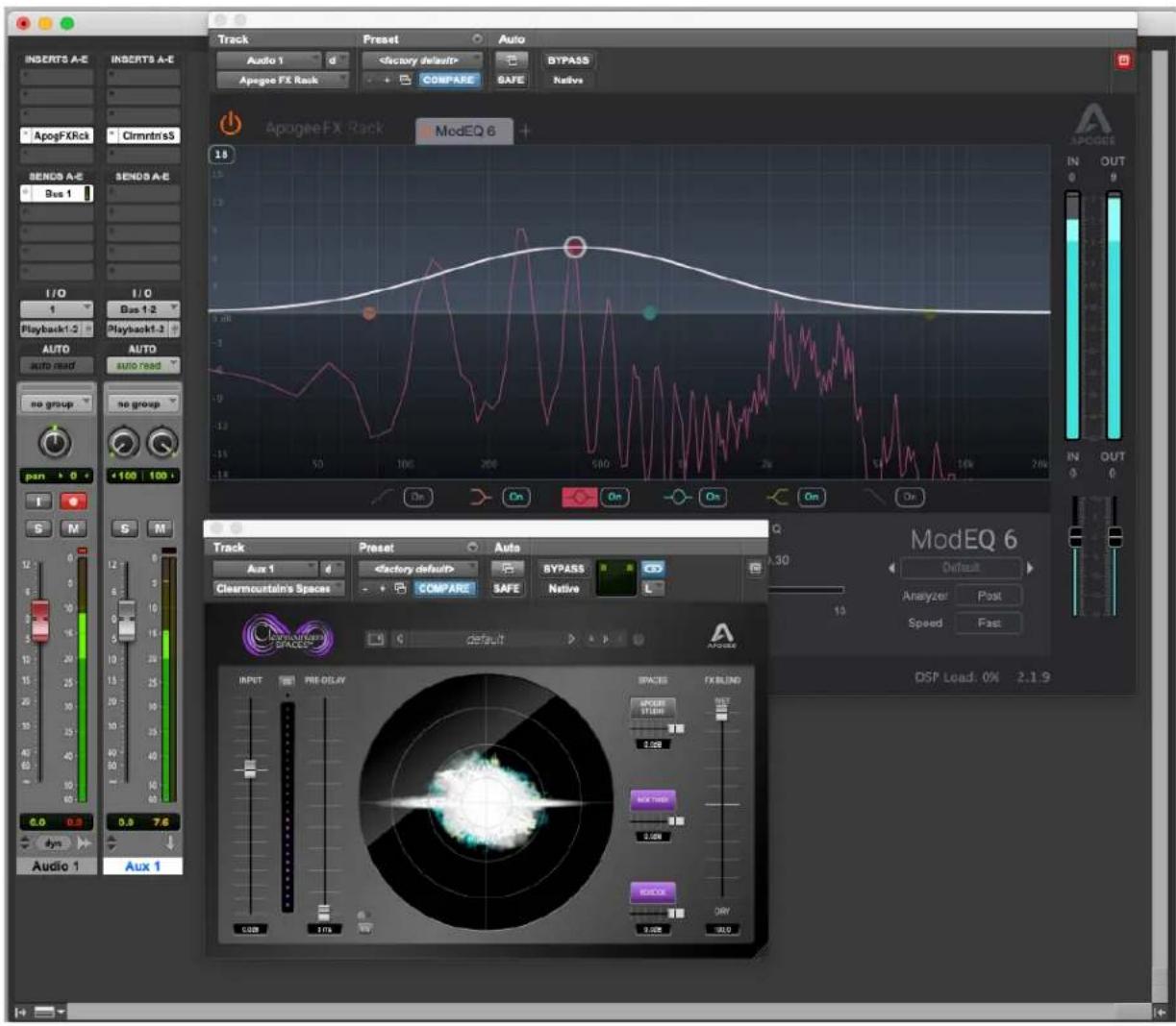
Ableton Live
To configure Ableton Live to use Symphony Desktop:
- In the Live menu bar, choose Live > Preferences and click the Audio tab.
- Mac - set Driver Type to CoreAudio; Windows - set Driver Type to Apogee ASIO Driver.
- Set Audio Input Device and Audio Output Device to Symphony Desktop.
- Set Buffer Size to 128 Samples to start, adjust for lower latency or more plugin power.
To configure Ableton Live for Direct or Software Monitoring Workflow:
- Monitor settings in Ableton Live are configured for each channel individually.
- In the Ableton menu bar, choose View and verify that In/Out is checked.
- In each channel, set Monitor to Auto for Software monitoring or Off for Direct monitoring.
- On the touch screen System Settings Page 1 or in Desktop Control, set Main and Headphone Sources.
- Set to Playback 1-2 for Software monitoring.
- Set to Mixer 1 for Direct monitoring.


To set channel Input & Output list labels:
- Choose Live > Preferences and click the Audio tab.
- Under Audio Device, click the Input Config and Output Config buttons.
- Activate inputs & outputs by clicking the numbered buttons. Once activated, enter your preferred label, i.e. Analog IN 1, Playback 1-2.
Choose which audio hardware inputs to make available to Live's tracks. Every input pair can be used as one stereo in and/or two mono ins. Deactivating inputs reduces the CPU load.
Mono Inputs
| 1 & 2 | Analog In 1 | Analog In 2 |
| 3 & 4 | ||
| 5 & 6 | ||
| 7 & 8 | ||
| 9 & 10 |
Stereo Inputs
| 1/2 | |
| 3/4 | |
| 5/6 | |
| 7/8 | |
| 9/10 |
Additional Notes
When using the Channel FX plugin linked to a hardware input, plugin metering is only displayed during playback, when Ableton channel Monitor is set to Off.
Troubleshooting
For more information
- Apogee KnowledgeBase and FAQs
• Informational Videos - Apogee Product Registration
- How to contact Apogee Technical Support
Please visit:
www.apogeedigital.com/support
Specifications
System Requirements
Computer
• MacOS 10.13 or greater
- Windows 10 Anniversary update or later
- iOS 13 or greater
- Memory: 4GB RAM minimum, 8GB recommended
- Connection: Any available USB 2 or 3 port
• Power: DC Power supply included
Compatible Software:
- All major DAW applications on Mac, Windows 10 and iOS
- Recommended apps: Logic Pro, Pro Tools, Ableton Live, Garageband, MainStage, Final Cut Pro, Digital Performer, Studio One, Cubase and Nuendo, FL Studio, Reaper.
| Preamps, Inputs, and Outputs | |
| Mic Preamps | Gain: Up to 75 dB and advanced stepped gain circuit design Selectable 48v phantom power, Soft Limit and polarity invert EIN: 129dB (un-weighted) @ 60dB, 150 Ohm input Max input level: +20dBu Input impedance: 150 - 4K Ohm (default) Max Hi-Z input level: 14dBu Hi-Z input impedance: 220k/470k/>20M Ohm |
| A/D Conversion: | Max input level (+4dBu ref/Mic): +20dBu Max input level (-10dBV ref): +6dBV Input impedance: 4KOhm Freq resp 10 Hz -20Khz: > +/-0.2dB (@44.1Khz) Rel. THD + N: -113dB Dyn. Range: 123dB (A-weighted) |
| D/A Conversion: | Max output level (+4dBu ref): +20dBu Max output level (-10dBV ref): +6dBV Line output impedance: 50 Ohm Freq resp 10Hz -20 Khz: > +/- 0.05dB (@44.1Khz) Rel. THD+N: -114dB Dyn Range: 129dB (A-weighted) Headphone Max output level: • 520mW into 30 Ohm • 90mW into 600 Ohm Headphone Rel THD+N: -111 dB with 600 Ohm load Headphone Dyn Range: 128dB (A-weighted) Headphone output impedance <0.5 Ohm |
| Weights and Dimensions | |
| 1.85 lbs 8.0" width x 4.75" depth x 1.25" to 2.5" height | |
Warranty Information and Legal Notices
APOGEE ELECTRONICS CORPORATION warrants this product to be free of defects in material and manufacture under normal use for a period of 12 months. The term of this warranty begins on the date of sale to the purchaser from an authorized Apogee dealer (proof of purchase in the form of a receipt may be required). Units returned for warranty repair to Apogee or an authorized Apogee warranty repair facility will be repaired or replaced with a functional equivalent product that is new or refurbished at the manufacturer's option, free of charge. Please note this guarantee may be subject to other conditions as dictated by the customer's legal warranty rights under the applicable national legislation governing the sale of consumer goods.
Apogee reserves the right to change or improve design at any time without prior notification. Design changes are not implemented retroactively, and the incorporation of design changes into future units does not imply the availability of an upgrade to existing units. This warranty is void if Apogee determines, in its sole business judgment, the defect to be the result of abuse, neglect, alteration or attempted repair by unauthorized personnel. The buyer acknowledges and agrees that in no event shall the company be held liable for any special, indirect, incidental or consequential damages, or for injury, loss or damage sustained by any person or property, that may result from this product failing to operate correctly at any time.
Warranty details are subject to change. For the latest warranty information please visit www.apogeedigital.com.
Declarations of Conformity
This device complies with Part 15 of the FCC Rules. Operation is subject to the following two conditions:
(1) This device may not cause harmful interference and (2) This device must accept any interference received, including interference that may cause undesired operation. This equipment has been tested and found to comply with the limits of a Class B digital device, pursuant to Part 15 of the FCC Rules.
CAUTION: Changes or modifications not expressly approved by Apogee Electronics Corporation compliance could void the user's authority to operate the equipment.
Rating: 5V 400mA USB 2.0
Industry Canada Notice
This Class B digital apparatus meets all requirements of the Canadian
Declaration of Conformity – CE
Apogee Electronics Corporation hereby declares that the product, Symphony Desktop, to which this declaration relates, is in material conformity with the following standards or other normative documents:
(EN50081-1/EN55022; 1995) and (EN50082-1/IEC 801-2, 3, 4; 1992)
following the provisions of: (73/23/EEC – Low Voltage Directive) and (89/336/EEC – EMC Directive)
Declaration of Conformity – CE
Apogee Electronics Corporation hereby declares that the product, Symphony Desktop, to which this declaration relates, is in material conformity with the following standards or other normative documents:
(EN50081-1/EN55022; 1995) and (EN50082-1/IEC 801-2, 3, 4; 1992)
following the provisions of: (73/23/EEC - Low Voltage Directive)
and (89/336/EEC - EMC Directive)
Declaration of Conformity – Japan Apogee Electronics Corporation hereby declares that Symphony Desktop, to which this declaration relates, is in material conformity with the VCCI Class A standard.
Declaration of Conformity – Australia
Apogee Electronics Corporation hereby declares that Symphony Desktop is in material conformity with AN/NZS standard requirements.
User's Guide Version 1.30a


- Symphony Desktop User's Guide
- Contents
- Contents 2
- Overview 4
- Getting Started 10
- TFT Touch Screen Control 21
- Apogee Control 2 Software 39
- Apogee Alloy Mic Preamp Emulation 48
- Apogee Channel FX Rack 50
- Choose Your Symphony Desktop Workflows 61
- Overview
- Introduction
- Put the Sound of a Symphony on Your Desktop
- Features
- Symphony Analog-to-Digital Conversion
- Symphony Digital-to-Analog Conversion
- Immersive Touch screen
- Apogee Alloy Mic Preamp Emulation
- Innovative Workflows with Hardware DSP
- Apogee Plugins Included
- Zero-Ohm Headphone Outputs
- Advanced Stepped Gain Mic Preamps
- Navigating This User's Guide
- In the Box
- System Requirements
- Register your Product
- Getting Started
- Installing Apogee Desktop Software
- macOS Installer
- Windows 10 Installer
- iPad Pro/iPhone
- Connecting Symphony Desktop
- AC Power
- Connecting to a Mac or Windows computer
- Connecting to an iPad Pro (USB-C)
- Connecting to an iOS Device
- Update Touch Screen Control
- On macOS:
- On Windows 10:
- Configure OS to use Symphony Desktop for Audio I/O
- macOS
- Windows 10
- Apple iOS
- How to Reset Symphony Desktop
- Connecting Your Studio
- TFT Touch Screen Control
- Navigating the Touch screen Interface
- I/O Views
- I/O Home View
- Input 1 & 2 Overview
- SD-MP (Symphony Desktop)
- AP-66 Preamp
- AP-57 Preamp
- Input 1-2 Settings
- Apogee Channel FX
- Apogee FX Plugins on the Touch Screen
- Main Out Overview
- Main Out Settings
- Headphone Out 1-2 Overview
- Headphone Out 1-2 Settings
- Mixer Views
- Mixer Overview
- Channel Settings
- Optical Input Views
- System Settings Views
- Page 1 - Routing
- Shutdown/Display Sleep
- Apogee Control 2 Software
- Primary Window
- Tool Bar
- System Settings Sidebar
- Channel Section
- General Settings
- Optical IN Channels
- Mixer Section
- Monitor/Output Section
- Menu Bar Menus
- Getting Started with the AP-57
- Apogee Channel FX Rack
- Channel Link
- Rack Controls
- Using the Channel FX Plugin
- Apogee Symphony Desktop User's Guide
- DAW Automation and Channel FX
- Channel FX On/Off Controls
- Channel FX Mono/Stereo Configuration
- Channel FX DSP Instance Count
- Choose Your Symphony Desktop Workflows
- A Glossary of Important Workflow Concepts
- Monitoring Workflows
- Software Monitoring
- Direct Monitoring
- DSP Processing Workflows
- Print FX
- Monitor FX & DualPath Monitoring
- Monitor FX & Software Monitoring
- Additional Workflows
- Mix Inputs Before Recording
- Configuring Your DAW
- Apple Logic Pro
- To configure Apple Logic Pro to use Symphony Desktop:
- To configure Logic Pro for Direct or Software Monitoring Workflow:
- To access Symphony Desktop inputs & outputs in Logic Pro:
- Direct Monitoring with Apogee FX plugins - Logic Pro and Symphony Desktop:
- Avid Pro Tools
- To configure Avid Pro Tools to use Symphony Desktop:
- To configure Pro Tools for Direct or Software Monitoring Workflow:
- To set channel Input & Output list labels:
- Pro Tools Preference Setting
- Ableton Live
- To configure Ableton Live to use Symphony Desktop:
- To configure Ableton Live for Direct or Software Monitoring Workflow:
- Additional Notes
- Troubleshooting
- For more information
- Specifications
- Computer
- Compatible Software:
- Warranty Information and Legal Notices
- Declarations of Conformity
Brand : Apogee
Model : Symphony Desktop
Category : Hi-Fi System