
PMD-706 - Dictaphone MARANTZ - Free user manual and instructions
Find the device manual for free PMD-706 MARANTZ in PDF.


| Product Type | Professional Digital Voice Recorder |
| Brand | Marantz |
| Model | PMD-706 |
| Category | Portable Audio Recorder |
| Power Supply | 4 AA batteries (alkaline, NiMH, lithium) or USB (AC adapter or computer) |
| Recording Formats | BWF 16/24 bits, WAV 16/24 bits |
| Sampling Frequencies | 44.1 kHz, 48 kHz, 96 kHz |
| Number of Channels | 6 channels (up to 6 mono or 3 stereo pairs) |
| Inputs | 2× XLR+6.35mm combo (front), 2× XLR+6.35mm combo (rear), 2× 6.35mm (cables included), 1× external input 3.5mm, 1× camera input 3.5mm |
| Outputs | 1× Line Out 3.5mm, 1× headphone output 3.5mm, 1× camera output 3.5mm |
| Phantom Power | +24V or +48V, selectable per channel (max 4 channels with USB power) |
| Storage Media | SD card (Quick format available) |
| Main Functions | Mono/stereo recording, two-channel, Mid/Side, mix, limiter, low-pass filter, slate tone, AES encryption |
| Display | Backlit LCD screen with level indicators, navigable menu |
| Connectors | Micro-USB (power and transfer), camera hot shoe mount |
| Dimensions | Not specified in manual, approximately 200×150×60 mm (estimated) |
| Weight | Not specified, approximately 1 kg with batteries (estimated) |
| Maintenance | Clean with a dry cloth; avoid moisture and shocks; disconnect before cleaning |
| Safety | Turn off phantom power before connecting/disconnecting microphones; use a stable tripod |
| Spare Parts | Not specified, compatible with standard tripod and standard cables |
| General Information | Professional, ideal for journalism, video production, field recording |
Frequently Asked Questions - PMD-706 MARANTZ
User questions about PMD-706 MARANTZ
0 question about this device. Answer the ones you know or ask your own.
Ask a new question about this device
Download the instructions for your Dictaphone in PDF format for free! Find your manual PMD-706 - MARANTZ and take your electronic device back in hand. On this page are published all the documents necessary for the use of your device. PMD-706 by MARANTZ.
USER MANUAL PMD-706 MARANTZ
User Guide (English)
Introduction
Box Contents
PMD-706
SD Card
Micro-USB Cable
(2) XLRF-1/4" TRS Cables
User Guide
Safety & Warranty Manual
Support
For the latest information about this product (documentation, technical specifications, system requirements, compatibility information, etc.) and product registration, visit marantzpro.com.
For additional product support, visit marantzpro.com/support.
Features
Front Panel
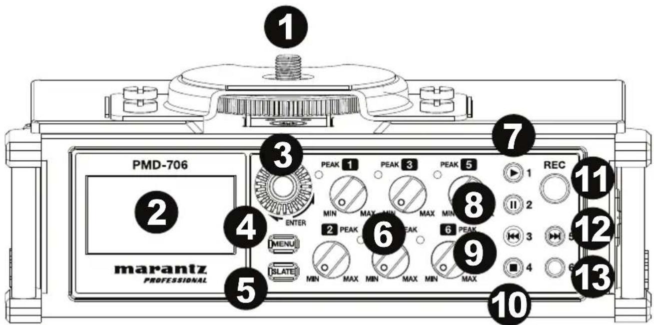
- Hot Shoe Mount: Attach a camera or lighting panel on top of this hot shoe mount.
- Display: Use this display to view and change PMD-706's settings. See the Setup chapter for examples of how to configure your settings in different scenarios.
- Enter Dial: Rotate the dial to select from the Menu options. Push the dial to select the current option.
- Menu: Push this button to show the menu options on the display. Press the Menu button again to return to the home screen. See Features >Menu Options for more details on navigating through the menus.
- Slate: Press and hold this button to mark a track with the slate sound. The slate tone generator allows for easy audio file alignment with video files when using video editing software.
- Input Level Control: Turn each knob to adjust the level of its corresponding input. The LED will turn red if the input signal is "clipping" or distorting. If this happens, turn down the Input Level control until the red LED is no longer illuminated.
- Input 1/Play: When in Playback mode, press this button to play an audio file. When in Menu mode, press this button to go to the CH1 column settings. When a file or folder is selected on the Browse screen, press this button to return to the Home screen and play the first file in the folder.
- Input 2/Pause: Press this button to pause an audio file when the unit is in playback mode. When in Menu mode, press this button to go to the CH2 column settings.
- Input 3/Rewind: When an audio file is playing in Playback mode, press and hold this button to search backward through the audio file. When an audio file is stopped in Playback mode, press and release this button to skip to the previous audio file. When in Menu mode, press this button to go to the CH3 column settings.
- Input 4/Stop: When in Playback mode, press this button to stop an audio file during playback or recording. Use this button to answer "NO" to a confirmation message on a setting screen. When in Menu mode, press this button to go to the CH4 column settings.
- Record: When a formatted SD card is in the SD card slot, press this button to start recording. See Features >Menu Options >Media for details on formatting a SD card.
- Input 5/Fast Forward: When an audio file is playing in Playback mode, press and hold this button to search forward through the audio file. When an audio file is stopped in Playback mode, press and release this button to skip to the next audio file. When in Menu mode, press this button to go to the CH5 column settings.
- Input 6: When in Menu mode, press this button to go to the CH6 column settings.
Rear Panel
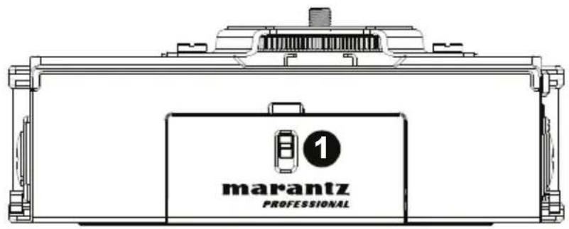
- Battery Compartment: Insert 4 AA batteries into this compartment to power the unit.
Note: If recording with 4 or more channels using 48V phantom power, a USB power adapter or a computer's USB bus power must be used in order to provide the necessary power (1A) to all channels.
Bottom Panel
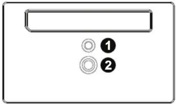
- Tripod Locking Hole: Attach your tripod here for a secure connection.
- 1/4" Threaded Insert: Connect your mounting adapter from a tripod here.
natural_image
Simple diagram of a device panel with two circular components labeled 1 and 2 (no text or symbols beyond labels)Right Side Panel
- Power On/Off/Hold Switch: Slide this switch down to power PMD-706 on or off. Slide this switch up to activate or deactivate the Hold feature. When Hold is activated, all of PMD-706's buttons will be disabled to prevent accidental changes.
- XLR+1/4" TRS Inputs: Connect a microphone or line-level device to these XLR+1/4" (6.35 mm) inputs.
- Micro USB Port: Connect this port to a computer with the included USB cable. This connection will power PMD-706. You can also
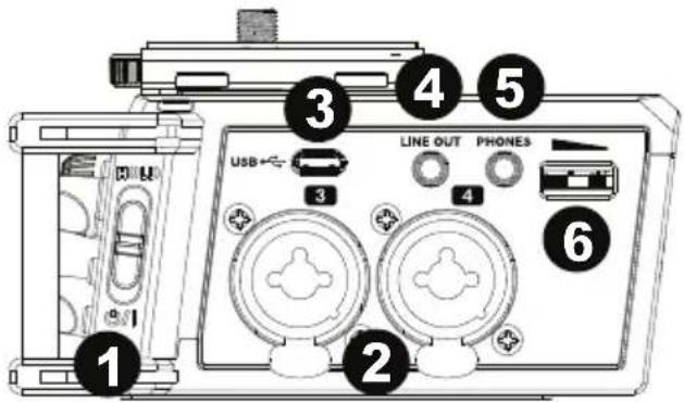
use this connection to transfer files between PMD-706 and your computer. You can also connect this port to a USB power adapter (sold separately) to power PMD-706 from a standard power outlet.
Note: If recording with 4 or more channels using 48V phantom power, a USB power adapter or a computer's USB bus power must be used in order to provide the necessary power (1A) to all channels.
- Line Out: Connect this 1/8" (3.5 mm) output to a mixer, another recorder, or powered speakers. Go to Menu > Output Control to adjust the volume output.
- Headphone Output: Connect this 1/8" (3.5 mm) output to headphones for monitoring the incoming audio signal or audio playback.
- Headphone Volume Control: Adjust the headphone output volume using this control.
Note: Before connecting any device (condenser or dynamic microphones, line-level devices, etc.) to any XLR, 1/4" input, or external inputs, ensure phantom power is turned off. Connecting or disconnecting devices to or from these inputs while phantom power is on can damage the device or PMD-706.
Left Side Panel
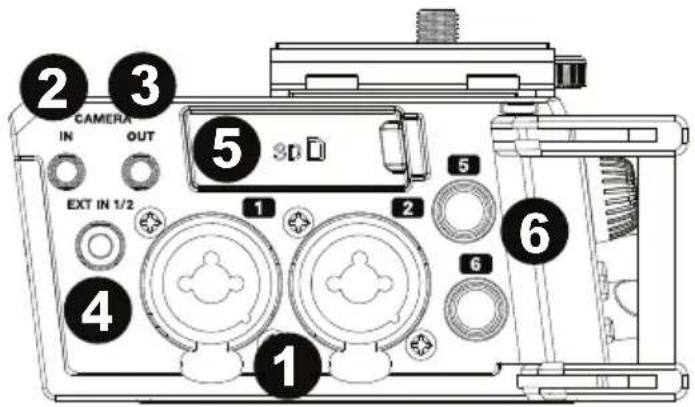
- XLR+1/4" TRS inputs: Connect a microphone or line-level device to these XLR+1/4" (6.35 mm) inputs.
- 1/8" (3.5 mm) Camera Input: Connect the audio output of a camera to this 1/8" (3.5 mm) TRS input.
- 1/8" (3.5 mm) Camera Output: Connect this 1/8" (3.5 mm) TRS output to the audio input of a camera. Go to Menu > Output Control to adjust the volume output.
- External Input: Connect a stereo
microphone or audio source to this 1/8" (3.5 mm) TRS input. See Menu > Mic Power to learn how to turn phantom power on or off for this input.
- SD Card Slot: Insert an SD card here.
- 1/4" (6.35 mm) Inputs: Connect a mic-level or line-level device to these 1/4" (6.35 mm) inputs using the included XLRF-1/4" cables. Phantom power can be supplied to these inputs.
Note: Before connecting any device (condenser or dynamic microphones, line-level devices, etc.) to any XLR, 1/4" input, or external inputs, ensure phantom power is turned off. Connecting or disconnecting devices to or from these inputs while phantom power is on can damage the device or PMD-706.
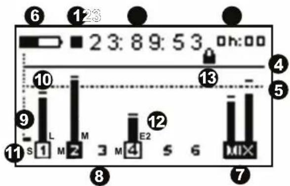
Home Screen Display
- Record/Pause/Stop indicator
- Elapsed time
- Remaining record time available
- 0 dB reference line
- -12 dB reference line
- Battery indicator
- Mix channel
- Channels 1-6 setup info
- Signal indicator bar
- Peak threshold
- Recording type: stereo (S), mono (M), dual (D)
- Input setting: mic (M), line (L), Ext 1 (E1), Ext 2 (E2)
- Encryption on/off
Channel Reporting Symbols
1 Channel is not active
1 Channel is active and has phantom power applied
1 Channel is active and has NO phantom power applied
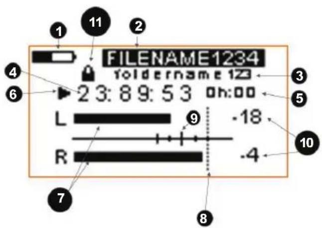
Play Screen
- Battery indicator
- File name
- Folder name
- Running time of playback
- Remaining time of playback
- Play/Stop/Pause/FF/Rewind indicator
- Left/Right playback meters
- 0 dB level
- Level indicators: -6 dB, -12 dB (major), -15 dB, -18 dB
- Digital readout of playback level
- Encryption on/off: See Menu 7 – Rec Set for details on how to enter an encryption key.
Note: If you try to play an encrypted file, you must enter the encryption key first.
Menu Options
Press the Menu button to show the menu options on the display. To move vertically on a page or to the next page, scroll with the Enter dial. To select a menu item or sub item, press the Enter dial and change the item's options by turning the dial. Press the Enter dial to confirm the item's changes. Use Input 1-6 buttons to jump to a specific column for CH1-CH6.
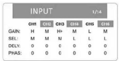
1. Input
Gain Setting (GAIN)
• L (Low)
• M (Mid)
• H (High)
- H+ (High Plus)
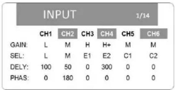
Selection (SEL)
- CH1-CH4
- M (mic level)
- L (line level)
• E1 (external 1) (1 or 3)
• E2 (external 2) (2 or 4) - CH5 & CH6
• M (mic level)
• L (line level)
• E1 (external 1) (5) / E2 (external 2) (6)
• C1 (Camera In 1) (5) / C2 Camera In 2 (6)
Delay (DELY): 0-300 ms (@ 44.1 kHz) in 1 ms increments 0-270 ms (@ 48 or 96 kHz) in 1 ms increments
Phase (PHAS): 0, 180
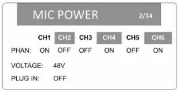
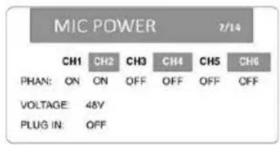
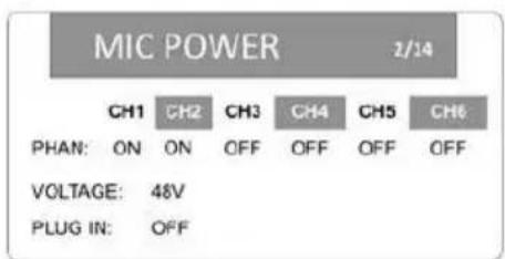
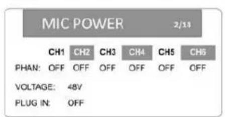
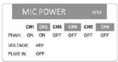
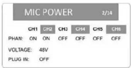
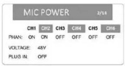
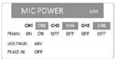
2. Mic Power
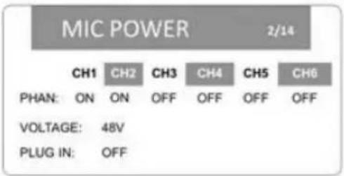
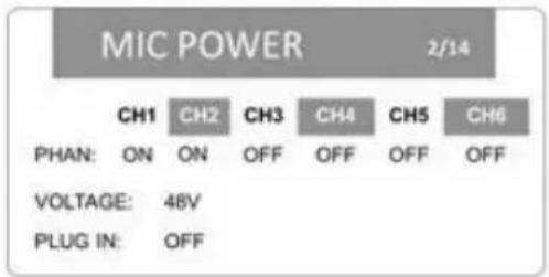
Phantom Power (PHAN): On, Off
Phantom Power Voltage (VOLTAGE): 24V, 48V
Plug-in Voltage for Ext Input (PLUG IN): On, Off
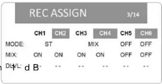
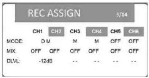
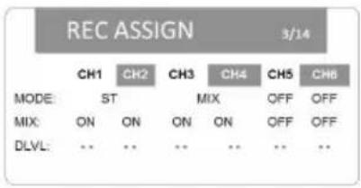
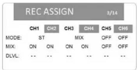
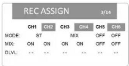
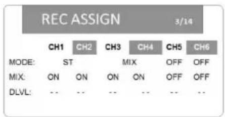
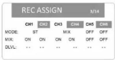
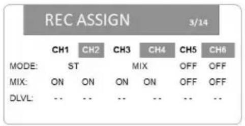
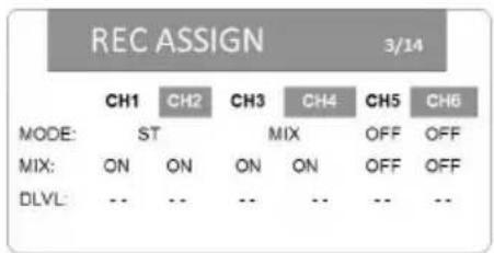
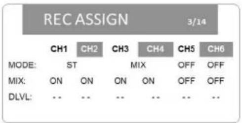
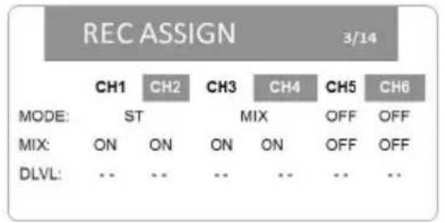
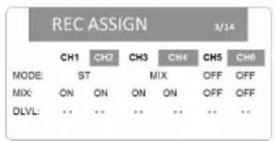
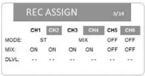
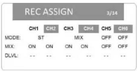
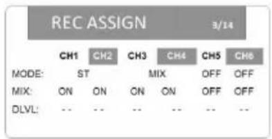
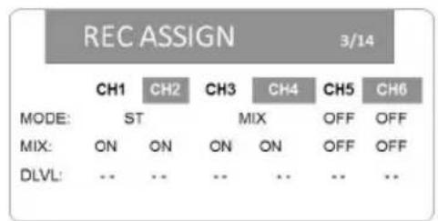
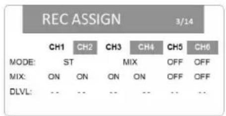
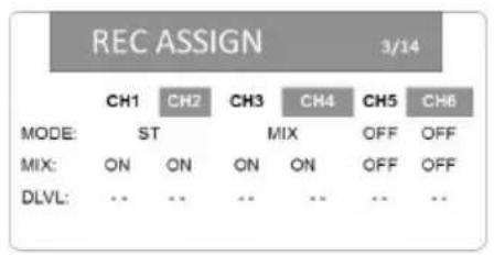
3. Rec (Record) Assign
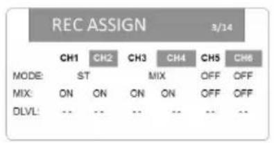
Recording Mode (MODE): M (mono), ST (stereo), DM (dual mono), DST (dual stereo), M/S R (mid/side recording), MIX
Mix Setting (MIX): On, Off
DLVL (Dual Level): -12 dB to -1 dB in increments (available only in dual mono and dual stereo modes)
Note: If sampling rate on Menu 7 – Rec Set is set to 96 kHz, CH5 and CH6 will be unavailable to use for recording.
4. Level Control
Limiter (LIM): Off, On, 3B (that channel only), LINK (CH1/2 and/or CH3/4), 3BAND (CH1/2 and/or CH3/4)
Auto Level Control (AUTO): On (all LIM settings will be set to OFF), Off
Low Cutoff Frequency (LCF): Off, 50 Hz, 80 Hz, 120 Hz, 180 Hz, 220 Hz
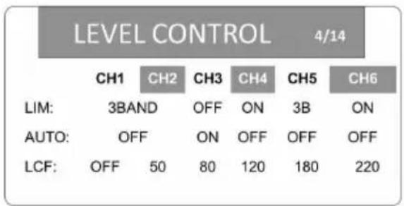
Note: The limiter can only be turned on if the sampling rate is 44.1/48 kHz. When set to ON or 3B, the limiter only affects the channel that has excessive input. When set to LINK or 3BAND, the limiter affects channels that have excessive input and the channels linked to them.
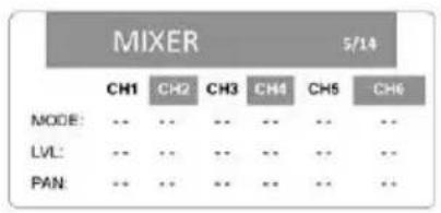
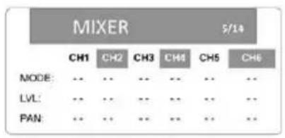
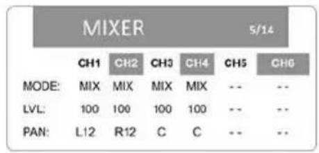
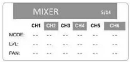
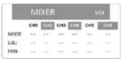
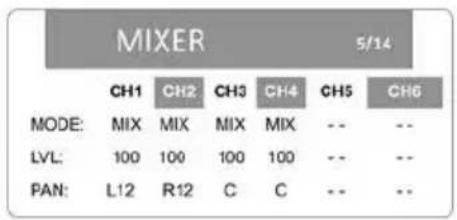
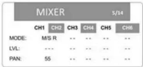
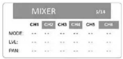
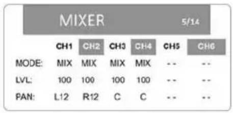
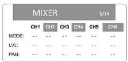
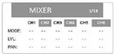
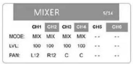
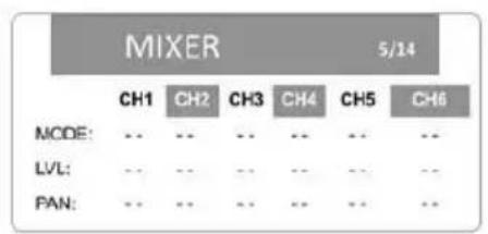
5. Mixer
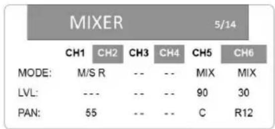
Recording Mode (MODE): M/S R (mid/side recording: record), M/S P (mid/side recording: playback), MIX
Level (LVL): --- (off), 0–100
other
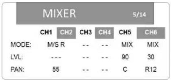
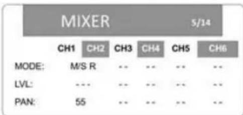
MIXER 5/14 | MODE | CH1 | CH2 | CH3 | CH4 | CH5 | CH6 | |---|---|---|---|---|---|---| | MODE: | M/S R | -- | -- | -- | MIX | MIX | | LVL: | --- | -- | -- | -- | 90 | 30 | | PAN: | 55 | -- | -- | -- | C | R12 |Panning (PAN): L1–12 (left), C (center), R1–12 (right)
Note: To set the MODE, use the Rec Assign Menu (3). To set the LVL when MODE is set to M/S P, use the Output Control Menu (6). To set the LVL when MODE is set to M/S R or MIX, use the Rec Assign Menu (3).
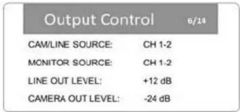
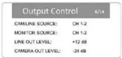
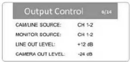
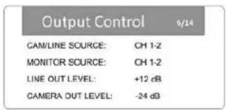
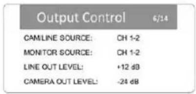
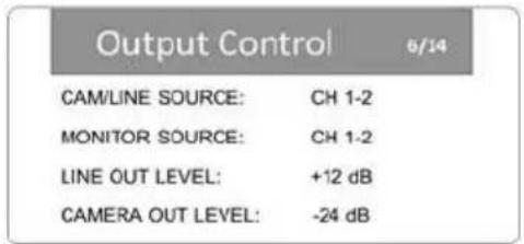
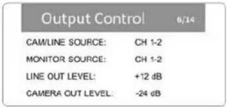
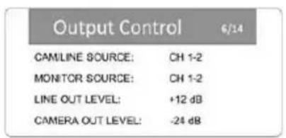
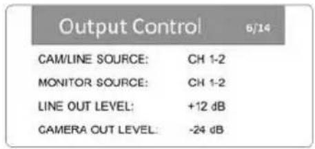
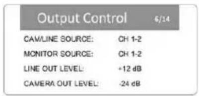
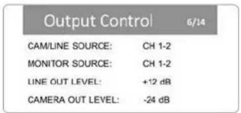
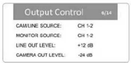
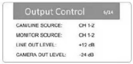
6. Output Control
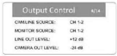
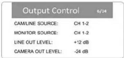
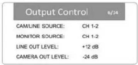
Camera/Line Source (CAM/LINE SOURCE) & Monitor Source (MONITOR SOURCE):
- MIX: sent to mix
- CH1-CH6: mono signal sent to left and right
- CH1-2: CH1 (left), CH2 (right)
- CH3-4: CH3 (left), CH4 (right)
- CH5-6: CH5 (left), CH6 (right)
- M/S 1-2: CH1+CH2 (left), CH1-CH2 (right)
- M/S 3-4: CH3+CH4 (left), CH3-CH4 (right)
- M/S 5-6: CH5+CH6 (left), CH5-CH6 (right)
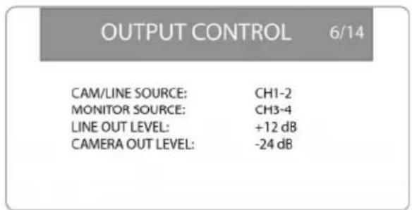
Line Out Level (LINE OUT LEVEL): -12 dB to +12 dB in 1 dB increments
Camera Out Level (CAMERA OUT LEVEL): -24 dB to +42 dB in 1 dB increments
7. Rec (Record) Set
Recorded File Format (FORMAT): BWF 16B (16-bit), BWF 24B (24-bit), WAV 16B (16-bit), WAV24B (24-bit)
Recording Sample Rate (SAMPLE RATE): 44.1 kHz, 48 kHz, 96 kHz
Note: If sampling rate on Menu 7 – Rec Set is set to 96 kHz, CH5 and CH6 will be unavailable to use for recording.
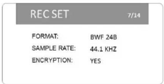
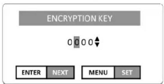
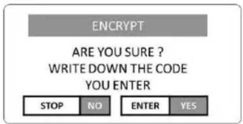
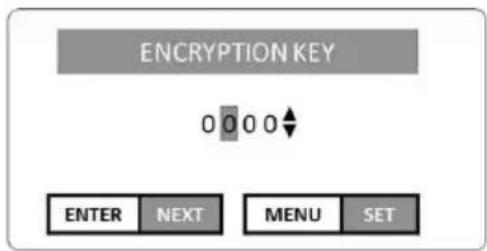
Encryption (ENCRYPTION): Yes, No. When creating an encryption key, use the Enter dial to change the numbers, press the Enter dial to enter each number, and press Menu to set the code and exit this screen.
8. Slate Settings
Automatic Slate (AUTO): Off, Head (start of recording), Head Tail (start and stop of recording)
Slate Volume (VOLUME): -36 dB to -12 dB in 1 dB increments
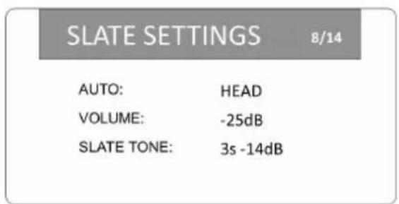
Slate Tone Settings (SLATE TONE): 1-# s (seconds), -14 dB to -20 dB (level)
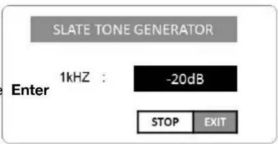
To set the slate tone, select SLATE TONE and press the Enter dial. Turn the Enter dial to set the volume level (-20 dB to -14 dB). Press the dial to start or stop the tone. Press Stop to save this level and return to the previous screen.
9. File
Create New Folder (NEW FOLDER): This creates a new folder on the SD card.
File Name Type (NAME TYPE): WORD (text), DATE (time/date)
File Name Text (WORD): up to 6 characters
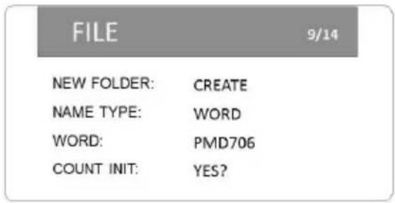
Count Initialize (COUNT INIT): This resets the sequential file numbering system used to name the file.
Files are named in the following way:
- When TYPE is set to WORD: WORD_File#_CH#_RecordingMode (e.g., PMD706_0001_CH1_M or PMD706_0003_CH34_St).
- When TYPE is set to DATE: YYYY_MM_DD_HH_MM_CH#_RecordingMode (e.g., 2017_05_16_17_CH3_M or 2017_03_10_08_CH34_St).
10. Gang Control
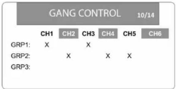
This screen allows you to link volume controls by creating 3 groups and tying any channel input to the same input level control. The input level control with the lowest number in a group will control the level for all of them.
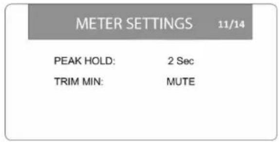
11. Meter Settings
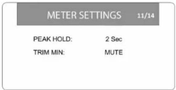
Peak Hold (PEAK HOLD): 1 sec, 2 sec, 10 sec, Hold, Off
Input Control Minimum Setting (TRIM MIN): -40 dB (from maximum setting), MUTE
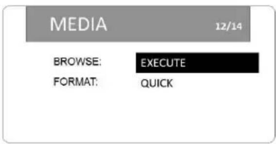
12. Media
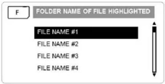
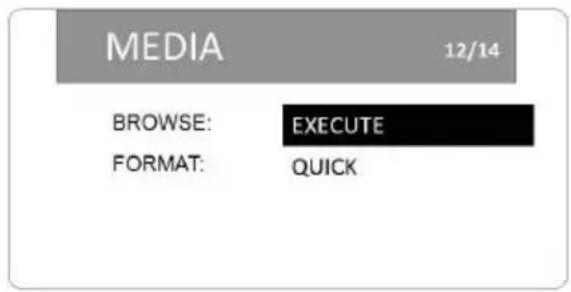
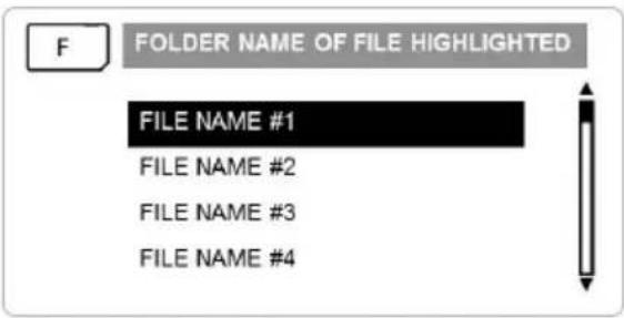
Browse Files (BROWSE): EXECUTE (to view sequential list of all files in the current folder; turn the Enter dial to scroll and press the Enter dial to play a file)
Format SD Card (FORMAT): QUICK (to format the SD card in the SD card slot)
When Browse is activated, a screen appears with all files listed sequentially in the current folder listed. Scroll through the files and press Enter to play a file.
Select Format and choose Quick to format the SD card.
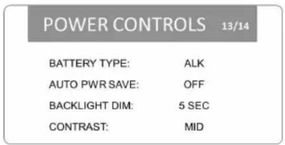
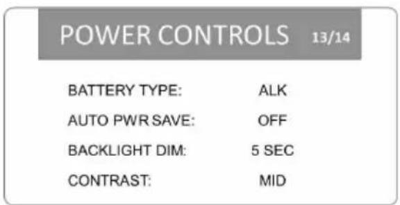
13. Power Controls
Battery Type (BATTERY TYPE): ALK (alkaline), NI-H (nickel-hydrogen), LIT (lithium)
Automatic Power Save (AUTO PWR SAVE): OFF, 3 MIN, 5 MIN, 10 MIN, 30 MIN
Backlight Dimming (BACKLIGHT DIM): 5 SEC, 15 SEC, 30 SEC, ALWAYS
Display Contrast (CONTRAST): Low, Mid, Hi
14. System
Initialize (INITIALIZE): This resets all PMD-706 settings to their original (factory) defaults.
Set Date & Time (DATE/TIME): Press the Enter dial to cycle through the year, month, day, hour, minute, and second. Turn the Enter dial to set each one. Press Menu to confirm the entire setting.
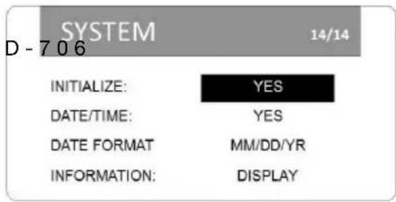
Date Format (DATE FORMAT): MM/DD/YY (month/day/year) or DD/MM/YY (day/month/year)
System Information (INFORMATION): BWF/WAV (audio format), TITLE (file name), DATE (date and time stamp), SIZE (file size and number of channels used), FILES (number of files on SD card), FOLDERS (number of folders on SD card), SD SIZE (total capacity of SD card), SD AVAIL (free space on SD card), AUTO POWER SAVE (automatic power saving time), AA/LI/NIH BATTERY LEVEL (battery life remaining), FIRMWARE VERSION (current firmware)
Operation
Setup
- Ensure the tripod is level, set on stable ground, and the tripod legs are securely locked in place.
- Attach the threaded insert on PMD-706 to your tripod mount, and use PMD-706's tripod locking hole, if needed.
- Attach your camera securely on top of PMD-706's hot shoe mount.
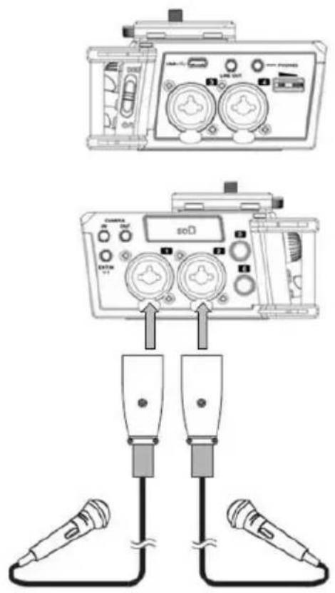
- Connect microphones or line-level devices to the XLR+1/4" inputs.
- Connect the audio output of your camera to the Camera Input on PMD-706 using an 1/8" (3.5 mm) cable.
- Connect PMD-706's Camera Output to the audio input of your camera using an 1/8" (3.5 mm) cable.
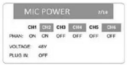
- If your microphone requires phantom power, select the appropriate voltage for your microphone from Menu > Mic Power.
- Adjust the input level controls to set the gain for the input signal for each channel.
- Connect headphones to the Headphone Output to monitor the audio input signal or to hear the audio playback from your camera.
See the following examples in this chapter to learn how to set up PMD-706 in specific scenarios.
Recording Modes
Mono: Record up to 6 mono tracks.
- Recorded File 1 = CH1
- Recorded File 2 = CH2
- Recorded File 3 = CH3
- Recorded File 4 = CH4
- Recorded File 5 = CH5
- Recorded File 6 = CH6
Stereo: Record up to 3 tracks in stereo pairs.
- Recorded File 1 = CH1 (left), CH2 (right)
- Recorded File 2 = CH3 (left), CH4 (right)
- Recorded File 3 = CH5 (left), CH6 (right)
Dual Mono:
- Recorded File 1 = CH1
- Recorded File 2 = CH1 - dlvl
- Recorded File 3 = CH3
- Recorded File 4 = CH3 - dlvl
- Recorded File 5 = CH5
- Recorded File 6 = CH5 - dlvl
Dual Stereo:
- Recorded File 1 = CH1 (left), CH2 (right)
- Recorded File 2 = CH1 -dlvl (left), CH2 -dlvl (right)
M/S R:
- Recorded File 1 = Left (CH1 + (CH2 x Pan Setting)), Right (CH1 - (CH2 x Pan Setting))
- Recorded File 2 = Left (CH3 + (CH4 x Pan Setting)), Right (CH3 - (CH4 x Pan Setting))
- Recorded File 3 = Left (CH5 + (CH6 x Pan Setting)), Right (CH5 - (CH6 x Pan Setting))
Setup Examples
Example 1 - Mono/Stereo Recording
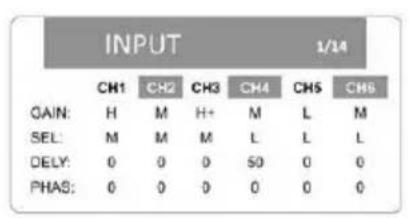
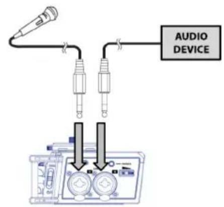
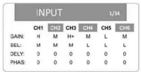
This example shows:
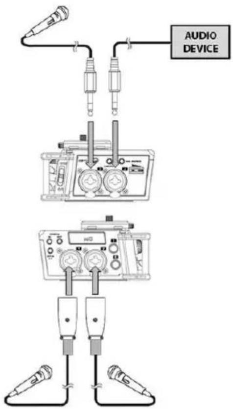
- condenser microphones on Inputs 1 and 2 (using +48V phantom power)
- a dynamic microphone on Input 3
- an audio device on Input 4 with a 50 ms delay
The menu options are configured to record a stereo file from Inputs 1 and 2 and two mono files from Inputs 3 and 4.
natural_image
Diagram of two connected electrical probes with arrows indicating connection points (no text or symbols present)The recorded files will be named as follows:
PMD706_0001_CH3_M.WAV
PMD706_0001_CH4_M.WAV
PMD706_0001_CH12_St.WAV
Example 2 – Stereo and Mix Recording
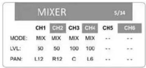
This example shows:
- condenser microphones on Inputs 1 and 2 (using +48V phantom power)
- a dynamic microphone on Input 3
- an audio device on Input 4
The menu options are configured to record a stereo file and mix track from Inputs 1 and 2 (with Left/Right level at 50%), Input 3 center panned, and Input 4 level at 75% (left) and 25% (right).
other
MIXER 5/14 | | CH1 | CH2 | CH3 | CH4 | CH5 | CH6 | |---|---|---|---|---|---|---| | MODE: | MIX | MIX | MIX | MIX | -- | -- | | LVL: | 50 | 50 | 100 | 100 | -- | -- | | PAN: | L12 | R12 | C | L6 | -- | -- |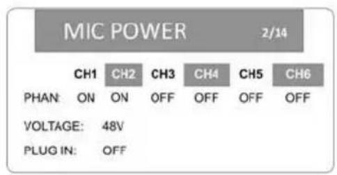
The recorded files will be named as follows:
PMD706_0001_CH12_St.WAV
PMD706_0001_CH34_MIX.WAV
Example 3 – Stereo and Mix Recording
This example shows:
- condenser microphones on Inputs 1 and 2 (using +48V phantom power)
- a dynamic microphone on Input 3
- an audio device on Input 4
The menu options are configured to record 4 mono files from Inputs 1-4 and a mix of Inputs 1-4 on tracks 5/6 with CH1 going to the left, CH2 to the right, and CH3 and CH4 mono.
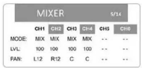
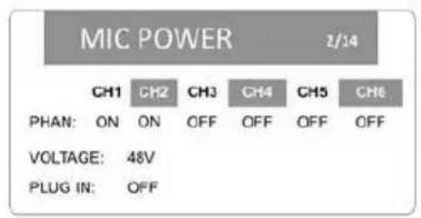
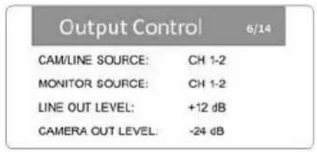
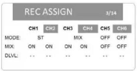
The recorded files will be named as follows:
PMD706_0001_CH1_M.WAV
PMD706_0001_CH2_M.WAV
PMD706_0001_CH3M.WAV
PMD706_0001_CH4_M.WAV
PMD706_0001_CH56_MIX.WAV
Example 4 – Dual Mono Recording
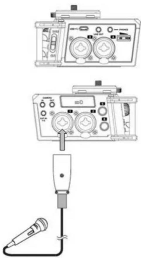
This example shows:
- a dynamic microphone on Input 1
The menu options are configured to record a dual mono file with the safety track at -9 dB lower than Input 1.
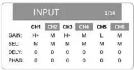
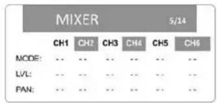
The recorded files will be named as follows:
PMD706_0001_CH1_DM1.WAV
PMD706_0001_CH1_DM2.WAV
Example 5 – Dual Stereo Recording
This example shows:
- condenser microphones on Inputs 1 and 2 (using +48V phantom power)
The menu options are configured to record a dual stereo file with the safety track at -12 dB lower than inputs 1 and 2. The left stereo channel will be CH1, and the right stereo channel will be CH2.
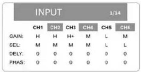
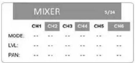
The recorded files will be named as follows:
PMD706_0001_CH12_DSt1.WAV
PMD706_0001_CH12_DSt2.WAV
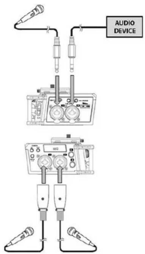
Example 6 - M/S Recording
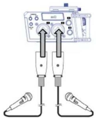
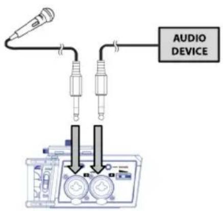
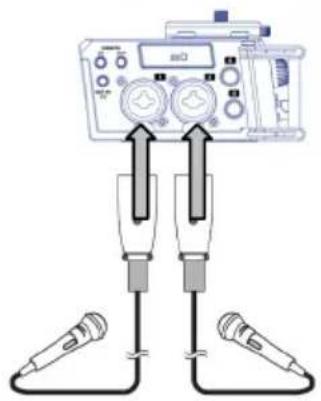
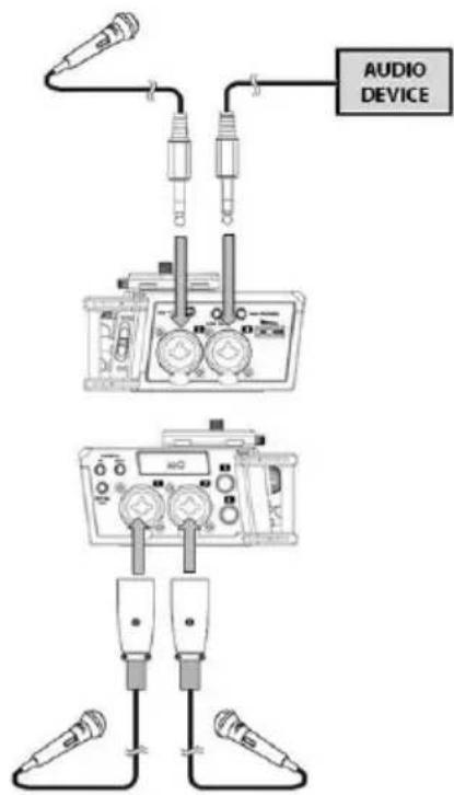
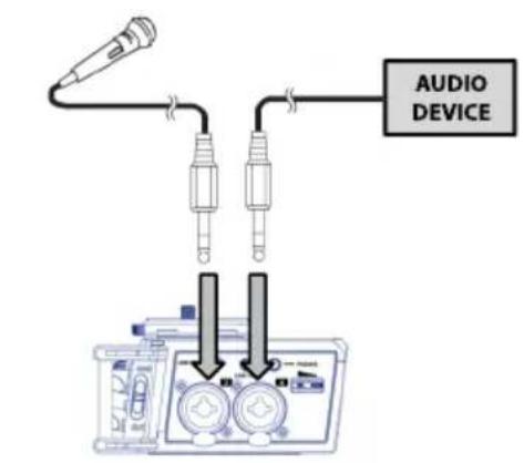
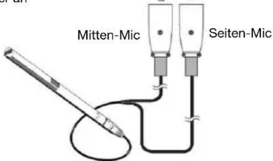
M/S (Mid/Side) recording consists of two microphones: a directional mic pointed towards the sound source and a figure 8 mic pointed towards the sides (Figure 1).
- Plug the mics into PMD-706 as shown in Figure 2. You can use Input 3 or 5 instead of Input 1 or 4, or you could use Input 6 instead of Input 2.
- To record without processing, use the M/S R mode. You will be able to monitor CH1 and CH2 without processing.
• To record without processing but monitor it with processing, use the M/S P mode. - To record without processing or monitoring it, use mono (M) recording for Input 1 and Input 2, or use stereo (ST) recording for Inputs 1/2.
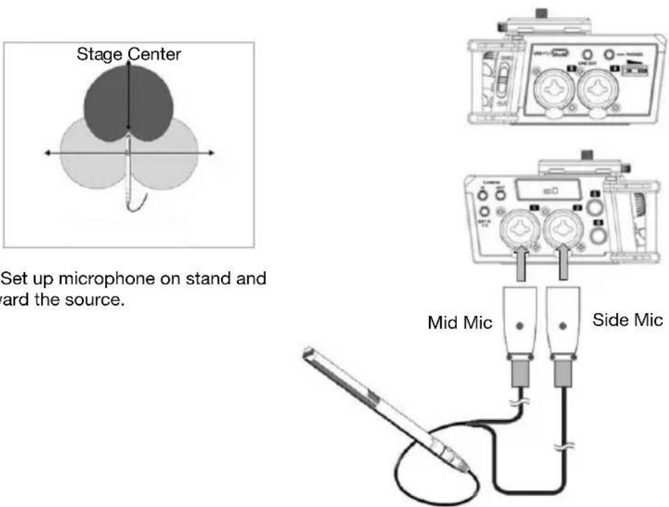
Figure 2: Connect mid and side mics to inputs.
Note: This example shows a specialized mid/side recording microphone. You could alternatively use a standard cardioid mic to capture the mid field and figure-8 mic (perpendicular to the cardioid mic) to capture the side fields.
M/S R Menus
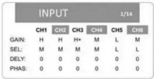
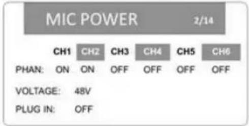
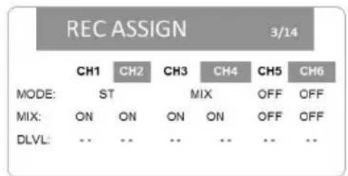
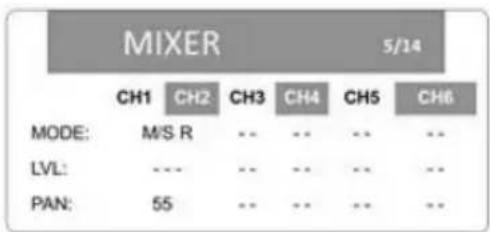
Panel lateral derecho
Ahorro de energía automático (AUTO PWR SAVE): OFF, 3 MIN, 5 MIN, 10 MIN, 30 MIN
natural_image
Diagram of two connected devices with arrows indicating connection points (no text or symbols present)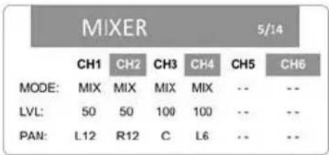
other
MIXER 5/14 | MODE | CH1 | CH2 | CH3 | CH4 | CH5 | CH6 | |---|---|---|---|---|---|---| | MODE: | MIX | MIX | MIX | MIX | -- | -- | | LVL: | 50 | 50 | 100 | 100 | -- | -- | | PAN: | L12 | R12 | C | L6 | -- | -- |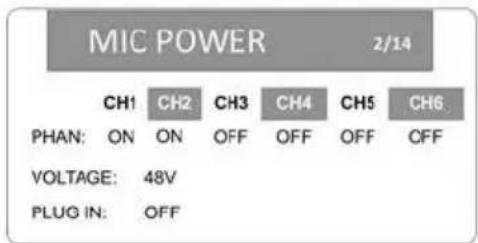
natural_image
Line drawing of a portable electronic device with two rotary buttons and control knobs (no text or symbols visible)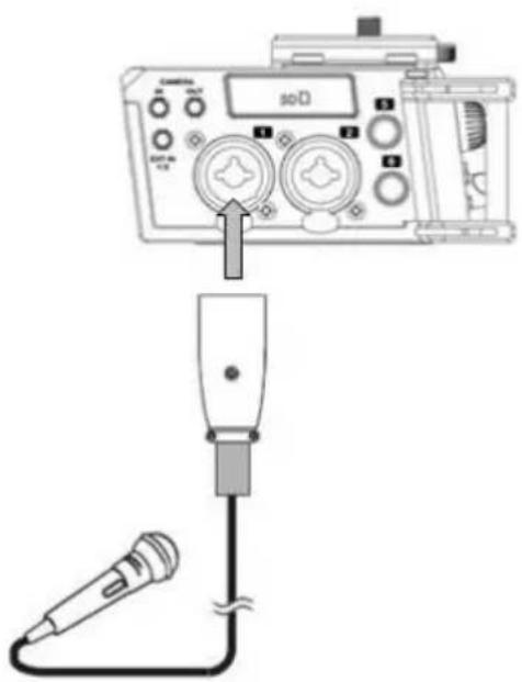
Assistance technique
natural_image
Simple diagram of a device panel with two circular components labeled 1 and 2 (no text or symbols beyond labels)Panneau droit
other
INPUT 1/14 | | CH1 | CH2 | CH3 | CH4 | CH5 | CH6 | |---|---|---|---|---|---|---| | GAIN: | H | M | H+ | M | L | M | | SEL: | M | M | M | L | L | L | | DELY: | 0 | 0 | 0 | 0 | 0 | 0 | | PHAS: | 0 | 0 | 0 | 0 | 0 | 0 |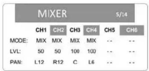
other
MIXER | MODE | CH1 | CH2 | CH3 | CH4 | CH5 | CH6 | |---|---|---|---|---|---|---| | MODE: | MIX | MIX | MIX | MIX | -- | -- | | LVL: | 50 | 50 | 100 | 100 | -- | -- | | PAN: | L12 | R12 | C | L6 | -- | -- |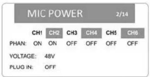
natural_image
Line drawing of a portable electronic device with two rotary buttons and control knobs (no text or symbols visible)other
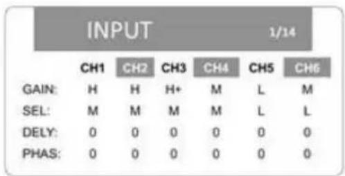
INPUT 1/14 | | CH1 | CH2 | CH3 | CH4 | CH5 | CH6 | |---|---|---|---|---|---|---| | GAIN: | H | H | H+ | M | L | M | | SEL: | M | M | M | M | L | L | | DELY: | 0 | 0 | 0 | 0 | 0 | 0 | | PHAS: | 0 | 0 | 0 | 0 | 0 | 0 |Menus M/S P
natural_image
Simple diagram of a device panel with two circular components labeled 1 and 2 (no text or symbols beyond labels)Livello (LVL): --- (off), 0–100
other
MIXER 5/14 | MODE | CH1 | CH2 | CH3 | CH4 | CH5 | CH6 | |---|---|---|---|---|---|---| | MODE: | M/S R | --- | --- | --- | MIX | MIX | | LVL: | --- | --- | --- | --- | 90 | 30 | | PAN: | 55 | --- | --- | --- | C | R12 |Panning (PAN): L1–12 (sinistra), C (centro), R1–12 (destra)
Formato file registrato (FORMAT): BWF 16B (16-bit), BWF 24B (24-bit), WAV 16B (16-bit), WAV 24B (24-bit)
natural_image
Diagram of a medical or laboratory setup with two connected devices and directional arrows indicating measurement or connection (no text or symbols present)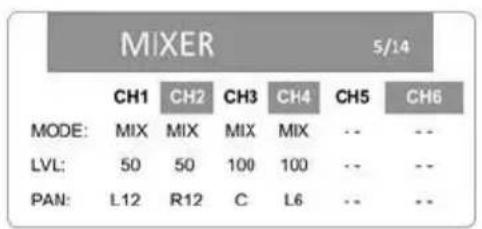
other
MIXER 5/14 | | CH1 | CH2 | CH3 | CH4 | CH5 | CH6 | |---|---|---|---|---|---|---| | MODE: | MIX | MIX | MIX | MIX | -- | -- | | LVL: | 50 | 50 | 100 | 100 | -- | -- | | PAN: | L12 | R12 | C | L6 | -- | -- |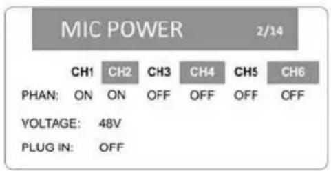
other
MIXER 5/14 | MODE | CH1 | CH2 | CH3 | CH4 | CH5 | CH6 | |---|---|---|---|---|---|---| | MODE: | MIX | MIX | MIX | MIX | -- | -- | | LVL: | 100 | 100 | 100 | 100 | -- | -- | | PAN: | L12 | R12 | C | C | -- | -- |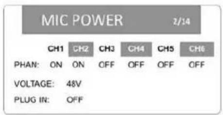
Rechte Seite
Automatischer Energiesparmodus (AUTO PWR SAVE): OFF, 3 MIN, 5 MIN, 10 MIN, 30 MIN
Hintergrund-Dimmer (BACKLIGHT DIM): 5 SEC, 15 SEC, 30 SEC, ALWAYS
Display-Kontrast (CONTRAST): Low, Mid, Hi
14. System
other
INPUT 1/14 | | CH1 | CH2 | CH3 | CH4 | CH5 | CH6 | |---|---|---|---|---|---|---| | GAIN: | H | M | H+ | M | L | M | | SEL: | M | M | M | L | L | L | | DELY: | 0 | 0 | 0 | 0 | 0 | 0 | | PHAS: | 0 | 0 | 0 | 0 | 0 | 0 |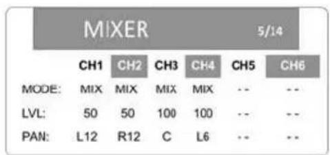
other
MIXER 5/14 | MODE | CH1 | CH2 | CH3 | CH4 | CH5 | CH6 | |---|---|---|---|---|---|---| | MODE: | MIX | MIX | MIX | MIX | -- | -- | | LVL: | 50 | 50 | 100 | 100 | -- | -- | | PAN: | L12 | R12 | C | L6 | -- | -- |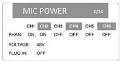
other
MIXER | MODE | CH1 | CH2 | CH3 | CH4 | CH5 | CH6 | |---|---|---|---|---|---|---| | MODE: | MIX | MIX | MIX | MIX | -- | -- | | LVL: | 100 | 100 | 100 | 100 | -- | -- | | PAN: | L12 | R12 | C | C | -- | -- |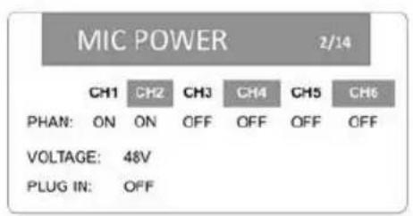
other
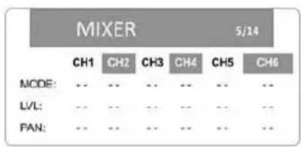
MIXER 5/14 | | CH1 | CH2 | CH3 | CH4 | CH5 | CH6 | |---|---|---|---|---|---|---| | MODE: | .. | .. | .. | .. | .. | .. | | LVL: | .. | .. | .. | .. | .. | .. | | PAN: | .. | .. | .. | .. | .. | .. |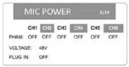
natural_image
Line drawing of a device control panel with buttons and dials (no text or symbols)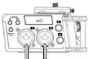
Technical Specifications
| Connectors | (4) XLR+1/4” (6.35 mm) inputs(2) 1/4” TRS (6.35 mm) inputs(2) 1/8” (3.5 mm) inputs(3) 1/8” (3.5 mm) outputs(1) Micro-USB port, Type B |
| Power | Via 4 AA batteries (Alkaline or NI-MH), USB bus power, or a USB power adapter.Consumption: 2 W (with phantom power off), 4 W (with 6 channels and phantom power on)Operating Humidity: 25–85%, non-condensingOperating Temperature: 41–140°F / 5–60°C |
| Battery Life | Up to 5.5 hours (with phantom power off) |
| Supported SD Media | SD card (64 MB – 2 GB)SDHC card (4 – 32 GB)SDXC card (48 – 128 GB) |
| Recording Channels | 6-channels (stereo × 3, mono × 6), 4-channels in Dual Stereo mode, 4 channels max with 96 kHz sampling rate |
| Recording Formats WAV | (44.1, 48, or 96 kHz; 16- or 24-bit)BWF (44.1, 48, or 96 kHz; 16- or 24-bit) |
| Recording Modes | Mono, Stereo, Dual Mono, Dual Stereo, Mid/Side Recording, Mix |
| Audio Performance Signal to Noise:93 dB (Line in -> Line Out)88-90 dB (Mic in -> Line Out)93 dB (Ext In -> Line Out)93 dB (Camera In -> Line Out)92 dB (Line In -> Phone Out)92 dB (Line In -> Camera Out)Frequency Response: 20 Hz–20 kHz (±1.0 dB)Input Impedance: 2 KΩPhantom Power: 48 V (±4 V, 10 mA/channel), 24 V (±4 V, 10 mA/channel) | |
| Audio Channels Inputs 1, 2, 3, 4 (set to Mic or Mic + phantom power)Input Impedance: 4.7 KΩMaximum Input Level: -8 dBuMic Input Gain: +28 dB (Low), +47 dB (Mid), +59 dB (High), +64 dB (Hi Plus)Inputs 1, 2, 3, 4, 5, 6 (set to Line)Input Impedance: 4.7 KΩStandard Input Level: 0 dBuMaximum Input Level: +12 dBuLine Input Gain: +0 dB (Low), +10 dB (Mid), +20 dB (High), +30 dB (Hi Plus) | |
| Audio Channels External Inputs 1 & 2 | |
| Input Impedance: 10 KΩMaximum Input Level: -1 dBVLow: +9 dB, Mid: +20 dB, High: +35 dB, Hi Plus: +45 dBCamera Input:Input Impedance: 1 KΩStandard Input Level: -10 dBVMaximum Input Level: +3 dBV1/8" (3.5 mm) Line Output:Output Impedance: 1 KΩMaximum Output Level: +3 dBV1/8" (3.5 mm) Camera Output:Output Impedance: 100 ΩMaximum Output Level: -4 dBV | |
| Dimensions(width x depth x height) | 4.3" x 6.5" x 2.0"10.9 x 16.5 x 5.1 cm |
| Weight | 1.20 lbs.0.54 kg |
Specifications are subject to change without notice.
Trademarks & Licenses
Marantz is a trademark of D&M Holdings Inc., registered in the U.S. and other countries. Marantz Professional products are produced by inMusic Brands, Inc., Cumberland, RI 02864, USA.
All other product names, company names, trademarks, or trade names are those of their respective owners.
marantzpro.com
- User Guide (English)
- Introduction
- Box Contents
- Support
- Features
- Front Panel
- Rear Panel
- Bottom Panel
- Right Side Panel
- Left Side Panel
- Home Screen Display
- Play Screen
- Menu Options
- Input
- Gain Setting (GAIN)
- Selection (SEL)
- Mic Power
- Rec (Record) Assign
- Level Control
- Mixer
- Output Control
- Camera/Line Source (CAM/LINE SOURCE) & Monitor Source (MONITOR SOURCE):
- Rec (Record) Set
- Slate Settings
- File
- Gang Control
- Meter Settings
- Media
- Power Controls
- System
- Operation
- Setup
- Recording Modes
- Dual Mono:
- Dual Stereo:
- M/S R:
- Setup Examples
- Example 1 - Mono/Stereo Recording
- This example shows:
- Example 2 – Stereo and Mix Recording
- Example 3 – Stereo and Mix Recording
- Example 4 – Dual Mono Recording
- Example 5 – Dual Stereo Recording
- Example 6 - M/S Recording
- Panel lateral derecho
- Assistance technique
- Panneau droit
- Rechte Seite
- Trademarks & Licenses
- marantzpro.com
Brand : MARANTZ
Model : PMD-706
Category : Dictaphone