
D 12W - Pregnant DYNACORD - Free user manual and instructions
Find the device manual for free D 12W DYNACORD in PDF.


User questions about D 12W DYNACORD
0 question about this device. Answer the ones you know or ask your own.
Ask a new question about this device
Download the instructions for your Pregnant in PDF format for free! Find your manual D 12W - DYNACORD and take your electronic device back in hand. On this page are published all the documents necessary for the use of your device. D 12W by DYNACORD.
USER MANUAL D 12W DYNACORD
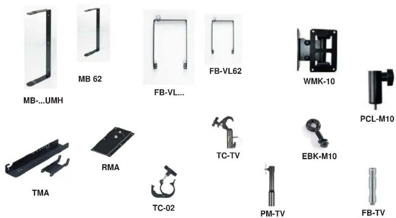
MB 62 (Mounting Bracket)
MB 262 UMH
MB 122 UMH
MB 152 UMH
MB VL212 (Mounting Bracket)
MB 500 UMH
MB 200 UMH
MB D8 UMH
FB-VL 62
FB-VL 262
FB-VL 122
FB-VL 152
FB-VL 212
FB-D15
FB-D8
FB-CXM 15
TMA (Tilt Mount Accessory)
RMA (Rotatable Mount Accessory)
TC-02 (Truss Clamp)
PCL-M10
PM-TV (Pole Mount TV Zapfen)
EBK-M10 (Eye Bolt Kit)
WMK-10 (Wall Mount Kit)

text_image
User Supplied Safety Cable
Sicherheitsfaktoren
MB 62 (Mounting Bracket)
natural_image
Technical line drawing of a mechanical bracket or frame assembly (no text or symbols)MB 62 (Mounting Bracket) D113138
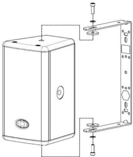
natural_image
Technical line drawing of a device housing with mounting bracket and internal components (no text or symbols)MB 262 UMH
natural_image
Technical line drawing of a vertical metal frame with mounting feet and mounting holes (no text or symbols)MB 262 UMH D113113

natural_image
Technical line drawing of a mechanical enclosure with mounting holes and internal components (no text or symbols)MB 122 UMH
natural_image
Technical line drawing of a rectangular device with mounting holes and a vertical support frame (no text or symbols)MB 152 UMH
natural_image
Technical line drawing of a rectangular industrial enclosure with internal components and mounting brackets (no text or symbols)MB VL212 (Mounting Bracket)
natural_image
Technical line drawing of a rectangular enclosure with a side panel and mounting bracket (no text or symbols)MB D8 UMH
natural_image
Technical line drawing of a mechanical enclosure with internal components and mounting holes (no text or symbols)MB 200 UMH
text_image
MB 200 UMH D170183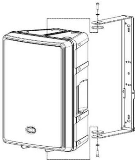
natural_image
Technical line drawing of a computer case with mounting brackets and internal components (no text or symbols)MB 500 UMH
natural_image
Technical line drawing of a mechanical assembly with flanged components and screw fasteners (no text or symbols)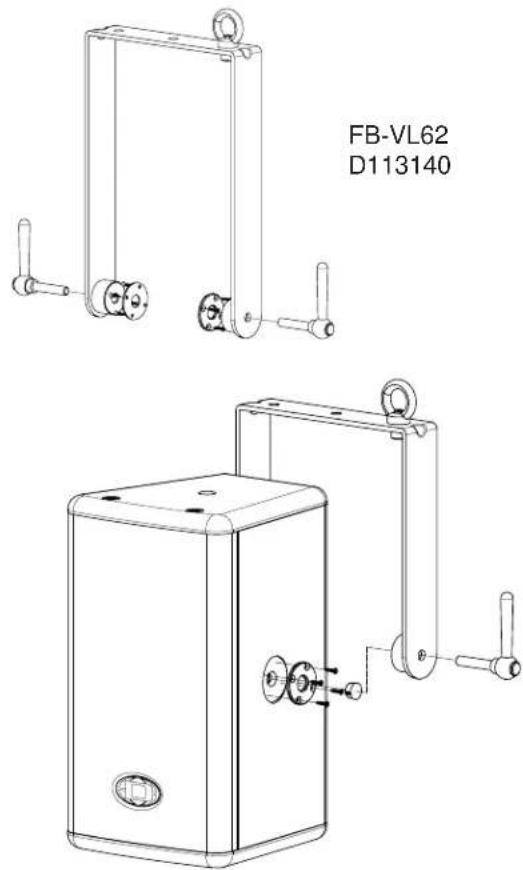
text_image
FB-VL62 D113140FB-VL262
natural_image
Technical line drawing of a mechanical assembly with flanged components and threaded fasteners (no text or symbols)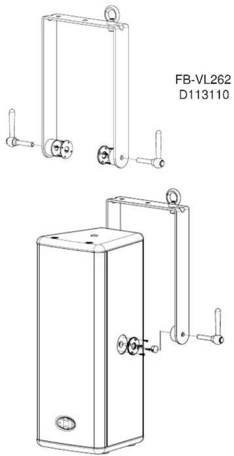
natural_image
Technical line drawing of two mechanical components with mounting holes and lever arms (no text or symbols)FB-VL122
natural_image
Technical line drawing of a mechanical assembly with flanges and bolts (no text or symbols)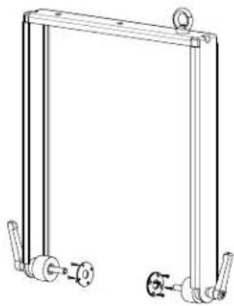
natural_image
Technical line drawing of a mechanical frame with two vertical supports and a central valve (no text or symbols)FB-VL122 D113111

natural_image
Line drawing of a rectangular industrial machine with a side panel and handle (no text or symbols)FB-VL152
natural_image
Technical line drawing of a mechanical assembly with flanged components and threaded fasteners (no text or symbols)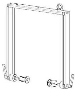
natural_image
Technical line drawing of a mechanical frame with two side supports and a central roller (no text or symbols)FB-VL152 D113112
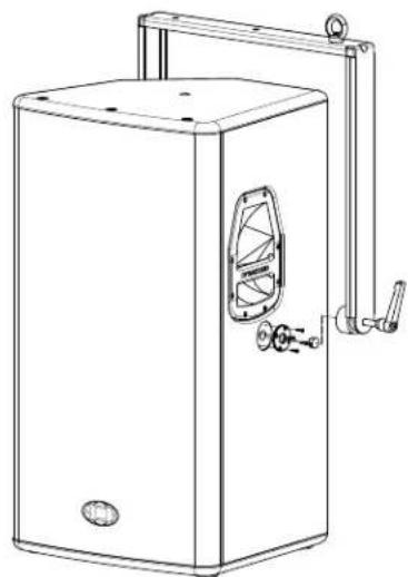
natural_image
Line drawing of a rectangular industrial machine with a side-mounted handle and control panel (no text or symbols)FB-VL212
natural_image
Technical line drawing of a mechanical assembly with bolts and shafts (no text or symbols)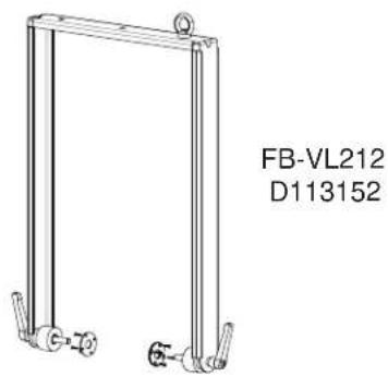
natural_image
Technical line drawing of a mechanical frame with two legs and a side-mounted knob, labeled FB-VL212 and D113152 (no other text or symbols)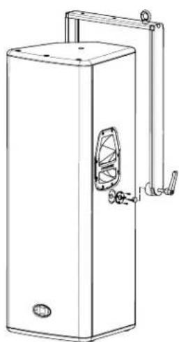
natural_image
Line drawing of a rectangular industrial vessel with a side-mounted handle and internal component (no text or symbols)FB-CXM 15
text_image
FB-CXM 15 D113299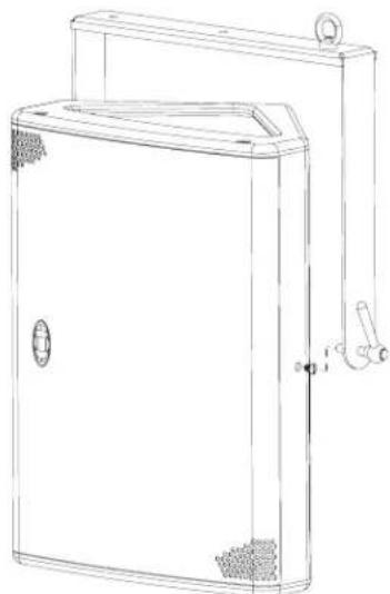
natural_image
Line drawing of a cabinet with handle and mounting bracket (no text or symbols)FB-D8
Flugbügel für D8
natural_image
Technical line drawing of a mechanical frame with two side handles and a circular top component (no text or symbols)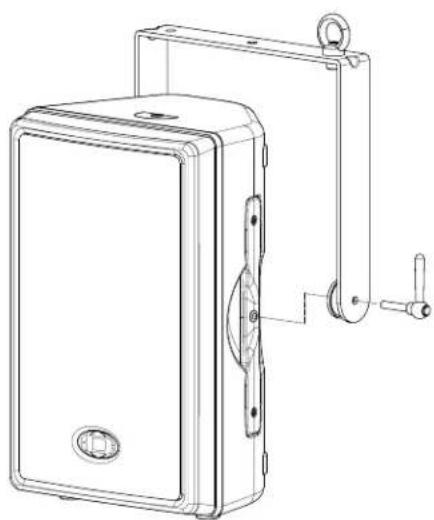
natural_image
Technical line drawing of a mechanical device with mounting bracket and handle (no text or symbols)FB-D15
Flugbügel für D15-3
natural_image
Technical line drawing of a wall-mounted device with mounting bracket and handle (no text or symbols)TMA (Tilt Mount Accessory)
natural_image
Two black metal structural components with mounting holes, one larger and one smaller, shown without any text or symbols.TMA (Tilt MountAccessory) D112815
text_image
Technical diagram of a mechanical assembly with numbered components for identificationRMA (Rotatable Mount Accessory)
natural_image
Black rectangular electronic component with mounting holes and a small metallic pin (no text or symbols visible)RMA (Rotatable Mount Accessory) D112807
natural_image
Technical line drawing of a mechanical linkage assembly (no text or symbols)TC-02 (Truss Clamp)
natural_image
Pure technical line drawing of a mechanical assembly without any text, numbers, or symbols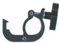
TC-02 (Truss Clamp)
D112808
natural_image
Technical line drawing of a mechanical clamp or bracket assembly (no text or symbols)PCL M10
natural_image
Pure mechanical diagram showing a U-shaped frame with two vertical supports and a central valve (no text or symbols)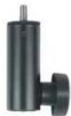
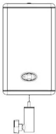
PCL M10
D113116
natural_image
Technical line drawing of a rectangular device with a central oval and attached mechanical component (no text or symbols)natural_image
Pure mechanical diagram of a frame structure without any text, numbers, or symbolsTC-TV (Truss Clamp TV Zapfen)
natural_image
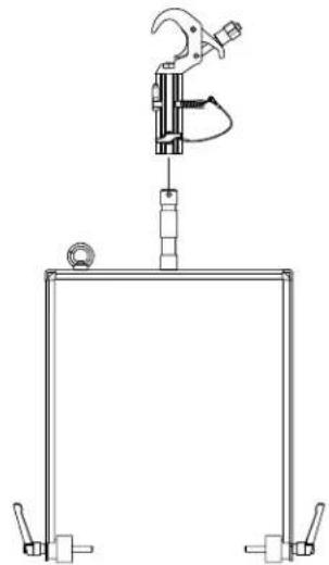
Close-up of a black mechanical clamp or clamp device with a handle and clasp (no visible text or symbols)TC-TV (Truss clamp TV Zapfen)
D112941
natural_image
Technical line drawing of a mechanical clamp device mounted on a frame structure (no text or symbols)PM-TV (Pole Mount TV Zapfen)
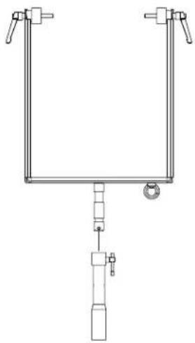
PM-TV (Pole Mount TV Zapfen)
D112942
natural_image
Pure mechanical diagram of a U-shaped clamp or bracket with no text, numbers, or symbolsEBK M10 (Eye Bolt Kit M10)
natural_image
Technical line drawing of a mechanical or electronic device with three stacked components and wiring (no text or symbols)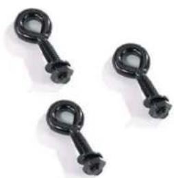
natural_image
Three black plastic chain link components with circular ends, arranged on a white background (no text or symbols visible)EBK M10 (Eye Bolt Kit M10)
D113155
natural_image
Technical line drawing of a mechanical or electrical enclosure with hanging connectors and internal components (no text or symbols)WMK 10 (Wall Mount Kit)
WMK-10 (Wall Mount Kit)
D113137
natural_image
3D mechanical assembly diagram showing a vertical panel connected to a black bracket with mounting holes and bolts (no text or symbols visible)Safety and assembling instructions
MB 62 (Mounting Bracket)
MB 262 UMH
MB 122 UMH
MB 152 UMH
MB 212 (Mounting Bracket)
MB 500 UMH
MB 200 UMH
MB D8 UMH
FB-VL 62
FB-VL 262
FB-VL 122
FB-VL 152
FB-VL 212
FB-D15
FB-D8
FB-CXM 15
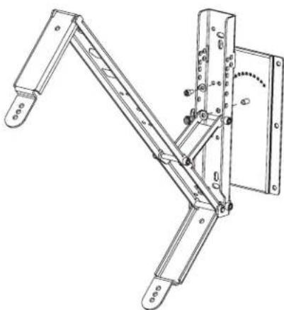
TMA (Tilt Mount Accessory)
RMA (Rotatable Mount Accessory)
TC-02 (Truss Clamp)
PCL-M10
FB-TV (Flight Bracket TV stud)
TC-TV (Truss Clamp TV stud)
PM-TV (Pole Mount TV stud)
EBK-M10 (Eye Bolt Kit)
WMK-10 (Wall Mount Kit)

General Safety References
Assembly accessories of Dynacord loudspeaker systems may be used exclusively considering the assembly instruction and in accordance with the BGV C1 regulations. In order to keep the safety criteria it will be expressly pointed out that an overload can be caused in the event of non-observance of the assembly instruction, changes of any kind of the accessories as well as installing the accessories to systems of other manufacturers.
All components may be connected only in the prescribed way and used in such a way.

General Assembling Instructions
For attachment at trusses, ceilings, walls etc. fixing material with sufficient ratings is to be used (DIN 18800) All such mountings are to be done by an experienced person. For all screw connections the given maximum ratings for the torques are to be kept (DIN 898).

Safeguards
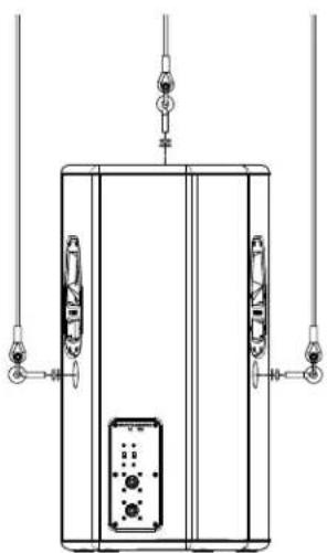
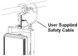
Loudspeaker systems are to be secured within the range of a stage or studios against tilting or falling down according to GUV 6.15 (BGV C1). This must happen with help of steel cables “(Safeties)” and/or chains, which are dimensioned for this working-load. A use of plastic-encased wire ropes is not permissible expressly. The safety devices specified in the regulations as well as the maximum head of 20cm are to be kept. Flown loudspeakers must be secured always against falling down by an additional, independent suspension point. This happens e.g. with a sufficiently dimensioned steel cable “(Safety)”.
text_image
User Supplied Safety Cable
Safety Factors
Accessories for the attachment of loudspeaker enclosures and PA systems are safety-relevant parts, which can endanger lives and health of humans during failure. Therefore the following guidelines were written, whose safety factors are to be kept. These are very highly put on due to wear, continuous stress etc. that also after use for many years still further safe handling can be ensured. Unfortunately many regulations in the reference to safety factors cannot be assigned always clearly and are often handled country-specifically.
Various standards specify the safety factors:
| Table according to BGV C1: | Safety factor |
| Chains, ropes, shackles, eye bolts, belts, hooks | Factor 12 |
| Accessories and their connection elements in mobile use | Factor 10 |
| Accessories and their connection elements for fixed installation | Factor 5 |

The maximum working load of manufacturers of commercial lifting and rigging hardware show usually other safety factors than demanded in thestage and studio areas.
| Table according to DIN 292-2: | |
| Lifting accessories Safety factor | |
| Wire ropes Factor 5 | |
| Chains from welded links Factor 4 | |
| Textile ber belts Factor 7 | |
| Metal parts Factor 4 | |

Inspection and Maintenance
For safety-relevant reasons a regular inspection of the accessories is inevitable. Prior to each use inspect the loudspeaker enclosures for any wear, deformation, notches, cracks and corrosion. Replace any damaged accessories immediately. In many states the regular inspection of attachment and accessories is prescribed. It is advisable to accomplish an annual inspection according to BGV C1 every 4 years by experienced technical personnel and additionally of a certified expert. In this connection leading of a test book is important, in which all accessories with their data and the recurring inspection are registered and are thus available at any time for potential controls.
 |  |  |  |  |  | [RTH2] |  |  |  |  |  |  |  |  |  |  | ||||
| CABINET Order-# | DUST-E COVER | EBOLT WALL KIT 3pcs. | -U-MOUNT MOUNT | UMH-MOUNT BRACKET | TILT-ROTOR BRACKET | FRAMBRACKET | *fr TRUSS PLATE | FB > fix STAND > TRUSS | FB > variable TRUSS | CLAMP | STAND | ADAPTER | TRUSS/STAND | FB-TV | FB > FB TRUSS | STAND | ||||
| VL 62 D113127 | SH-VL62 D113145 | EBK M10 D113155 | WMK-10 D113137 | MB 62 D113138 | ---- | ---- | ---- | TC-02 D112808 | FB-VL62 D113140 | TC-02 D112808 | FB-VL62 D113140 | PCL M10 D113116 | FB-VL62 D113140 | FB-TV D113142 | TC-TV D112941 | PM-TV D112942 | ||||
| VL 262 D113101 | SH-VL262 D113117 | EBK M10 D113155 | WMK-10 D113137 | ---- | MB 262 UMH D113113 | TMA D112815 | RMA D112807 | TC-02 D112808 | FB-VL262 D113110 | TC-02 D112808 | FB-VL62 D113140 | PCL M10 D113116 | FB-VL262 D113110 | FB-TV D113142 | TC-TV D112941 | PM-TV D112942 | ||||
| VL 122 D113103 | SH-VL122 D113118 | EBK M10 D113155 | ---- | ---- | MB 122 UMH D113114 | TMA D112815 | RMA D112807 | TC-02 D112808 | FB-VL122 D113111 | TC-02 D112808 | FB-VL122 D113111 | PCL M10 D113116 | FB-VL122 D113111 | FB-TV D113142 | TC-TV D112941 | PM-TV D112942 | ||||
| VL 152 D113104 | SH-VL152 D113119 | EBK M10 D113155 | ---- | ---- | MB 152 UMH D113115 | TMA D112815 | RMA D112807 | TC-02 D112808 | FB-VL152 D113112 | TC-02 D112808 | FB-VL152 D113112 | PCL M10 D113116 | FB-VL152 D113112 | FB-TV D113142 | TC-TV D112941 | PM-TV D112942 | ||||
| VL 212 D113133 | SH-VL212 D113147 | EBK M10 D113155 | ---- | MB-VL212 D113153 | ---- | ---- | ---- | TC-02 D112808 | FB-VL212 D113152 | TC-02 D112808 | FB-VL212 D113152 | PCL M10 D113116 | FB-VL212 D113152 | FB-TV D113142 | TC-TV D112941 | PM-TV D112942 | ||||
| D 8 D113126 | SH-D8 D113143 | ---- | WMK-10 D113137 | ---- | MB D8 UMH D113135 | TMA D112815 | RMA D112807 | TC-02 D112808 | FB-D8 D113136 | TC-02 D112808 | FB-D8 D113136 | PCL M10 D113116 | FB-D8 D113136 | FB-TV D113142 | TC-TV D112941 | PM-TV D112942 | ||||
| D 12 D113030 | SH-D12 D113046 | ---- | ---- | ---- | MB 200 UMH D170183 | TMA D112815 | RMA D112807 | TC-02 D112808 | ---- | ---- | ---- | ---- | ---- | ---- | ---- | ---- | ||||
| D 12A D113164 | SH-D12 D113046 | ---- | ---- | ---- | MB 200 UMH D170183 | TMA D112815 | RMA D112807 | TC-02 D112808 | ---- | ---- | ---- | ---- | ---- | ---- | ---- | ---- | ||||
| D 12R D121941 | SH-D12 D113046 | ---- | ---- | ---- | MB 200 UMH D170183 | TMA D112815 | RMA D112807 | TC-02 D112808 | ---- | ---- | ---- | ---- | ---- | ---- | ---- | ---- | ||||
| D 12T D121939 | SH-D12 D113046 | ---- | ---- | ---- | MB 200 UMH D170183 | TMA D112815 | RMA D112807 | TC-02 D112808 | ---- | ---- | ---- | ---- | ---- | ---- | ---- | ---- | ||||
| D 12-3 D113083 | SH-D12 D113046 | ---- | ---- | ---- | MB 200 UMH D170183 | TMA D112815 | RMA D112807 | TC-02 D112808 | ---- | ---- | ---- | ---- | ---- | ---- | ---- | ---- | ||||
| D 12-3A D113165 | SH-D12 D113046 | ---- | ---- | ---- | MB 200 UMH D170183 | TMA D112815 | RMA D112807 | TC-02 D112808 | ---- | ---- | ---- | ---- | ---- | ---- | ---- | ---- | ||||
| D 15-3 D113084 | SH-D15 D113097 | EBK M10 D113155 | ---- | ---- | MB 500 UMH D113099 | TMA D112815 | RMA D112807 | TC-02 D112808 | FB-D15 D113100 | TC-02 D112808 | FB-D15 D113100 | PCL M10 D113116 | FB-D15 D113100 | FB-TV D113142 | TC-TV D112941 | PM-TV D112942 | ||||
| CXM 15 F 01U123.094 | ---- | ---- | ---- | ---- | ---- | ---- | ---- | ---- | FB-CXM 15 D113299 | TC-02 D112808 | FB-CXM 15 D113299 | PCL M10 D113116 | FB-CXM 15 D113299 | FB-TV D113142 | TC-TV D112941 | PM-TV D112942 | ||||
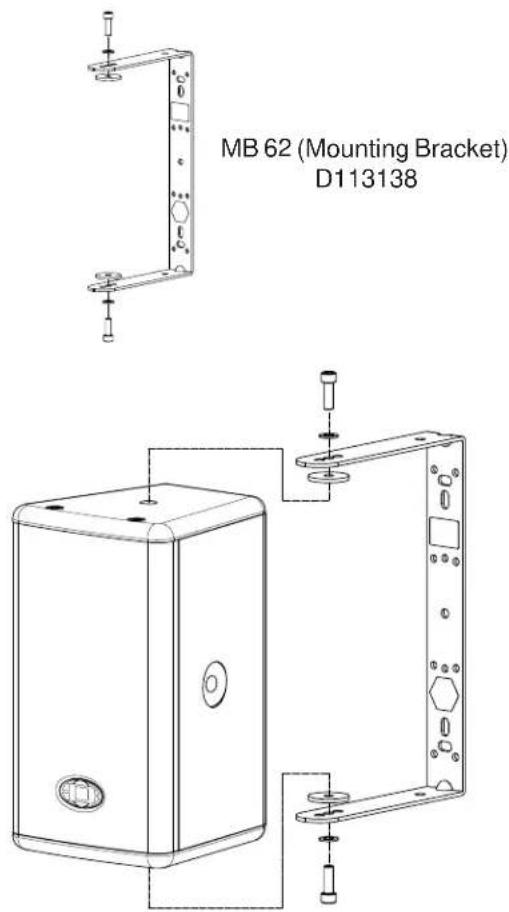
MB 62 (Mounting Bracket)
Simple wall and ceiling mounting bracket for VL 62, without slope mechanism.
Not combinable with TMA and RMA.
If bent installation is needed the WMK 10 must be used.
Assembly instruction:
The relevant assembly instructions at ceilings, walls or trusses are to be considered absolutely.
- Install MB 62 at the wall or ceiling with suitable mounting material.
- Remove the plastic covers of the necessary M10 threaded inserts at the enclosure.
- Unscrew the shaft screws from the threaded inserts.
- Insert enclosed rubber washer between bracket and enclosure. Bolt mounting bracket together with screw M10 and disk at the enclosure. Secure screws with thread locking compound.
Tighten screws.
text_image
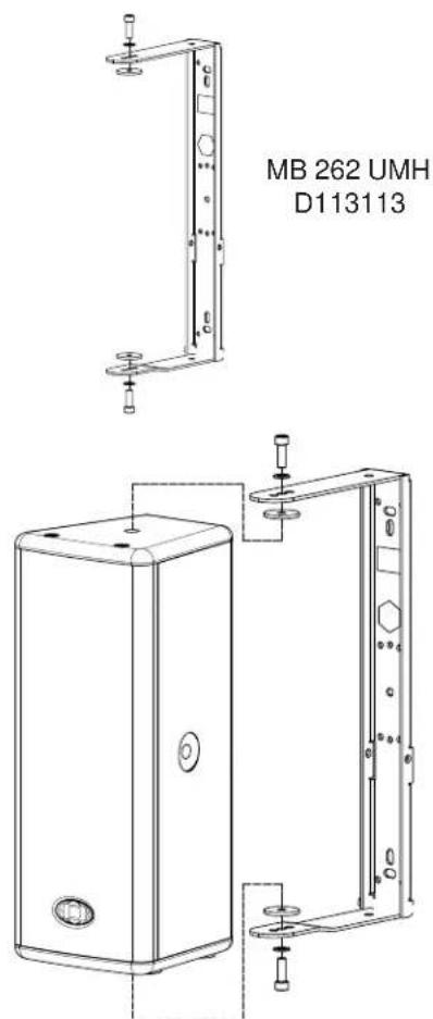
MB 62 (Mounting Bracket) D113138MB 262 UMH
Wall mounting bracket for VL 262.
Together with the TMA inclination angles between 5° and 45° can be adjusted in 5° steps. An adjustment to the listeners direction with turn-in to the wall is realized additionally with the RMA.
Assembly instruction:
The relevant assembly instructions at ceilings, walls or trusses are to be considered absolutely.
- Install MB 262 UMH at the wall or ceiling with suitable mounting material.
- Remove the plastic covers of the necessary M10 threaded inserts at the enclosure.
- Unscrew the shaft screws from the threaded inserts.
- Insert enclosed rubber washer between bracket and enclosure. Bolt mounting bracket together with screw M10 and disk at the enclosure. Secure screws with thread locking compound.
Tighten screws.
text_image
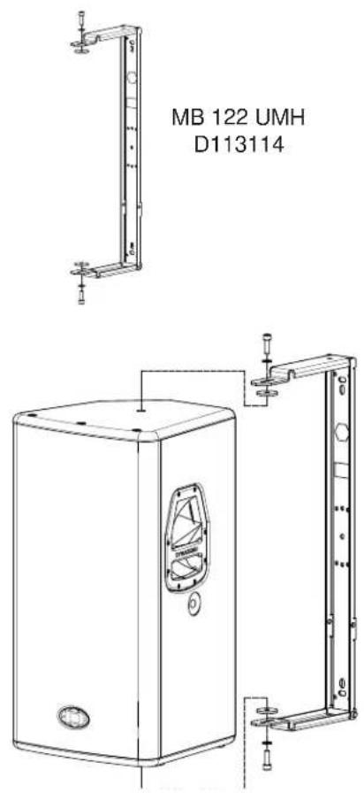
MB 262 UMH D113113MB 122 UMH
Wall mounting bracket for VL 122
Together with the TMA inclination angles between 5° and 45° can be adjusted in 5° steps. An adjustment to the listeners direction with turn-in to the wall is realized additionally with the RMA.
Assembly instruction:
The relevant assembly instructions at ceilings, walls or booms are to be considered absolutely.
- Install MB 122 UMH at the wall or ceiling with suitable mounting material
- Remove the plastic covers of the necessary M10 threaded inserts at the enclosure.
- Unscrew the shaft screws from the threaded inserts.
- Insert enclosed rubber washer between bracket and enclosure. Bolt mounting bracket together with screw M10 and disk at the enclosure. Secure screws with thread locking compound.
Tighten screws.
text_image
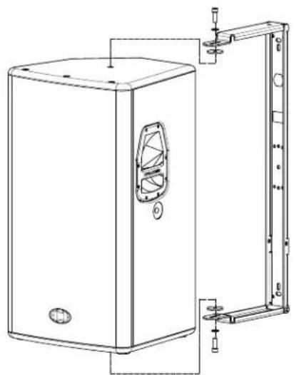
MB 122 UMH D113114MB 152 UMH
Wall mounting bracket for VL 152
Together with the TMA inclination angles between 5° and 45° can be adjusted in 5° steps. An adjustment to the listeners direction with turn-in to the wall is realized additionally with the RMA.
Assembly instruction:
The relevant assembly instructions at ceilings, walls or trusses are to be considered absolutely.
- Install MB 152 UMH at the wall or ceiling with suitable mounting material.
- Remove the plastic covers of the necessary M10 threaded inserts at the enclosure.
- Unscrew the shaft screws from the threaded inserts.
- Insert enclosed rubber washer between bracket and enclosure. Bolt mounting bracket together with screw M10 and disk at the enclosure. Secure screws with thread locking compound.
Tighten screws.
MB 152 UMH
D113115
natural_image
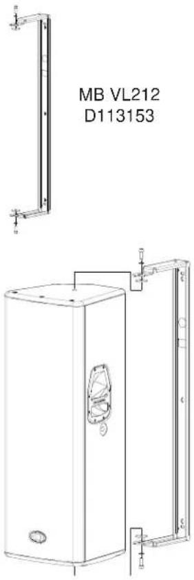
Technical line drawing of a rectangular industrial enclosure with internal components and mounting brackets (no text or symbols)MB VL212
Wall mounting bracket for VL 212
Not combinable with TMA and RMA.
Assembly instruction:
The relevant assembly instructions at ceilings, walls or trusses are to be considered absolutely.
- Install MB VL212 at the wall or ceiling with suitable mounting material.
- Remove the plastic covers of the necessary M10 threaded inserts at the enclosure.
- Unscrew the shaft screws from the threaded inserts.
- Insert enclosed rubber washer between bracket and enclosure. Bolt mounting bracket together with screw M10 and disk at the enclosure. Secure screws with thread locking compound.
Tighten screws.
text_image
MB VL212 D113153MB D8 UMH
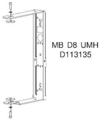
Wall mounting bracket for D8
Together with the TMA inclination angles between 5° and 45° can be adjusted in 5° steps. An adjustment to the listeners direction with turn-in to the wall is realized additionally with the RMA.
Assembly instruction:
The relevant assembly instructions at ceilings, walls or trusses are to be considered absolutely.
- Install MB D8 UMH at the wall or ceiling with suitable mounting material.
- Remove the plastic covers of the necessary M8 threaded inserts at the enclosure.
- Insert enclosed rubber washer between bracket and enclosure. Bolt mounting bracket together with screw M8 and disk at the enclosure. Secure screws with thread locking compound.
Tighten screws.
text_image
MB D8 UMH D113135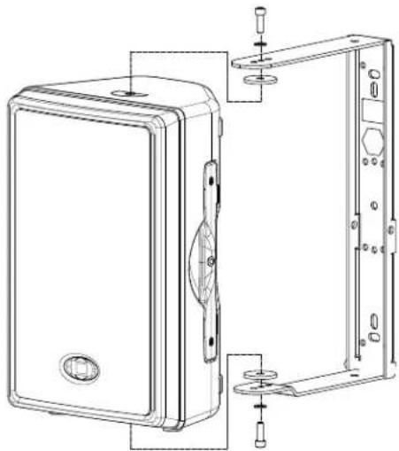
natural_image
Technical line drawing of a mechanical enclosure with internal components and mounting holes (no text or symbols)MB 200 UMH
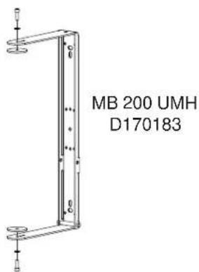
Wall mounting bracket for all D12 cabinet
Together with the TMA inclination angles between 5° and 45° can be adjusted in 5° steps. An adjustment to the listeners direction with turn-in to the wall is realized additionally with the RMA.
Assembly instruction:
The relevant assembly instructions at ceilings, walls or trusses are to be considered absolutely.
- Install MB 200 UMH at the wall or ceiling with suitable mounting material.
- Remove the feet of the D12 enclosure and insert the screws after removing the feet again.
- Remove the plastic covers of the necessary M8 threaded inserts at the enclosure.
- Insert enclosed rubber washer between bracket and enclosure. Bolt mounting bracket together with screw M8 and disk at the enclosure. Secure screws with thread locking compound.
Tighten screws.
text_image
MB 200 UMH D170183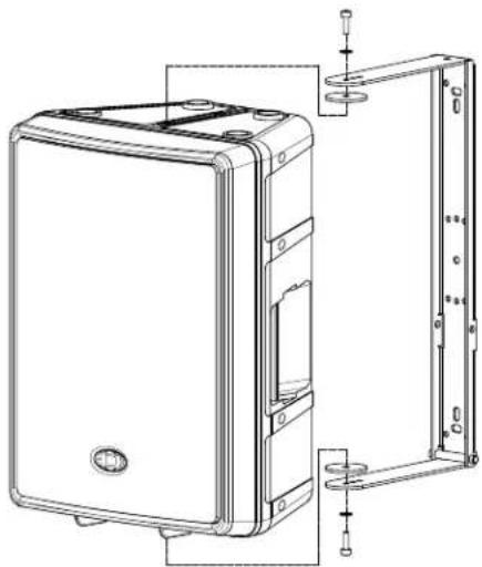
natural_image
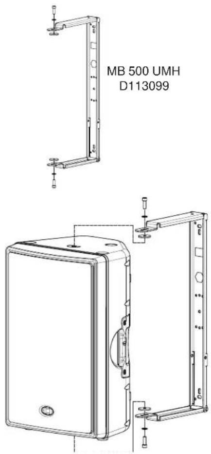
Technical line drawing of a computer case with mounting brackets and internal components (no text or symbols)MB 500 UMH
Wall mounting bracket for D15-3
Together with the TMA inclination angles between 5° and 45° can be adjusted in 5° steps. An adjustment to the listeners direction with turn-in to the wall is realized additionally with the RMA.
Assembly instruction:
The relevant assembly instructions at ceilings, walls or trusses are to be considered absolutely.
- Install MB 500 UMH at the wall or ceiling with suitable mounting material.
- Remove the feet of the D15-3 enclosure and insert the screws after removing the feet again.
- Remove the plastic covers of the necessary M10 threaded inserts at the enclosure.
- Insert enclosed rubber washer between bracket and enclosure. Bolt mounting bracket together with screw M10 and disk at the enclosure. Secure screws with thread locking compound.
Tighten screws.
text_image
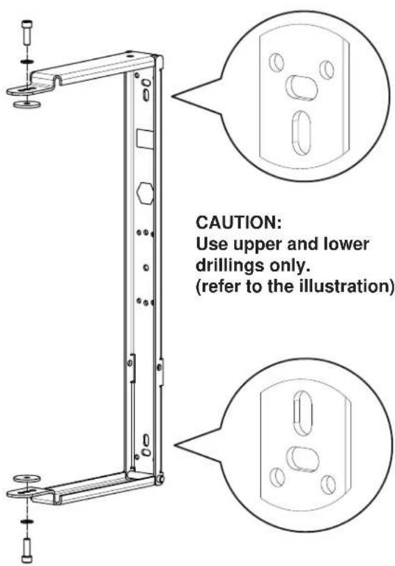
MB 500 UMH D113099Drillings for suitable mounting materials
text_image
CAUTION: Use upper and lower drillings only. (refer to the illustration)
Use adequately dimensioned rigging equipment (DIN 18800) when connecting to crossbeams, ceiling, walls, etc.
Leave all mounting and rigging to experienced personnel. Carefully abide default maximum clamping torque values for all screw joints (DIN 898).
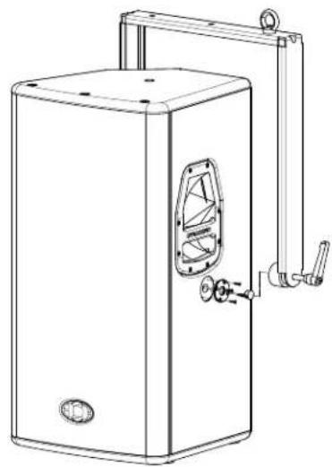
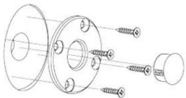
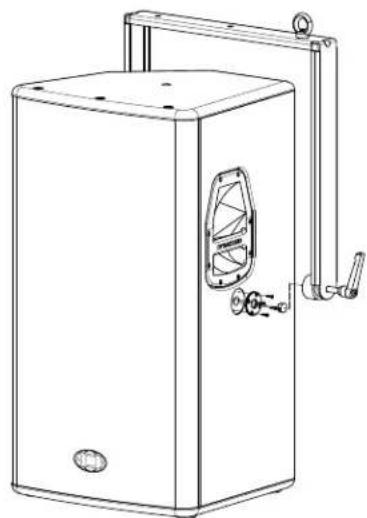
FB-VL 62
Flight bracket for VL 62.
The FB-VL 62 can be equipped for different assembly requirements in each case with PCL-M10, TC-02 or FB-TV.
Assembly instruction:
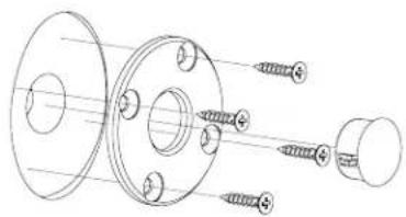
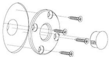
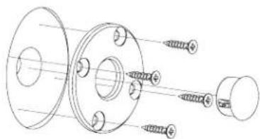
- Remove lateral plastic caps at the enclosure and keep it for further use. Unscrew shaft screws.
- Mount the wrinkle plates with the provided screws on the enclosure; the caps removed before can be used as a centering assistance.
- Push flight bracket from the rear onto the enclosure and screw it with the cone handles onto the enclosure.
- Make sure that the flight bracket is additionally secured against falling down during operation. For this the eye bolt mounted at the flight bracket should be used.
natural_image
Technical line drawing of a mechanical assembly with flanged components and threaded fasteners (no text or symbols)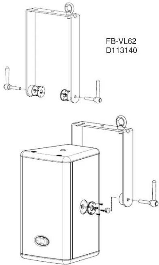
text_image
FB-VL62 D113140FB-VL 262
Flight bracket for VL 262.
The FB-VL 62 can be equipped for different assembly requirements in each case with PCL-M10, TC-02 or FB-TV.
Assembly instruction:
- Remove lateral plastic caps at the enclosure and keep it for further use. Unscrew shaft screws.
- Mount the wrinkle plates with the provided screws on the enclosure; the caps removed before can be used as a centering assistance.
- Push flight bracket from the rear onto the enclosure and screw it with the cone handles onto the enclosure.
- Make sure that the flight bracket is additionally secured against falling down during operation. For this the eye bolt mounted at the flight bracket should be used.
natural_image
Technical line drawing of a mechanical assembly with flanged components and threaded fasteners (no text or symbols)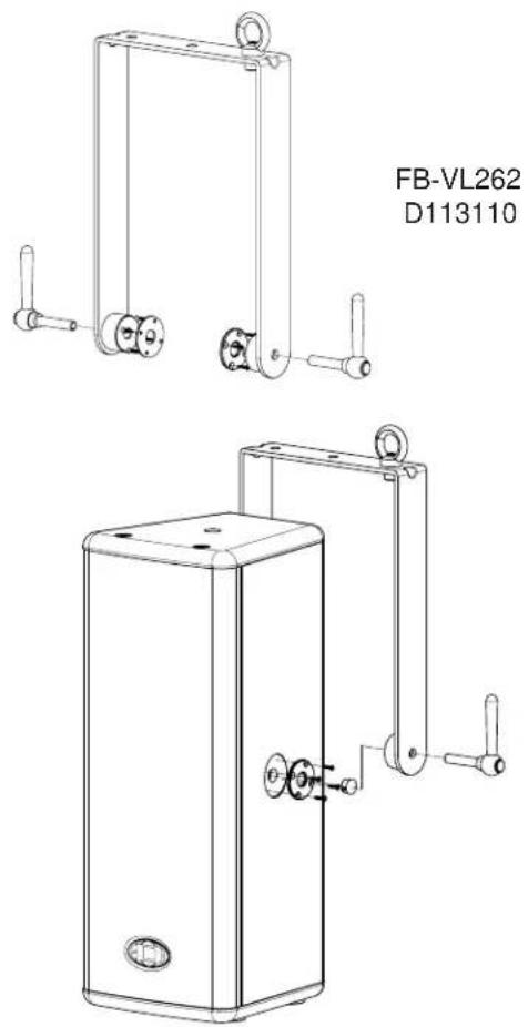
natural_image
Technical line drawing of two mechanical components with mounting holes and lever arms (no text or symbols)FB-VL 122
Flight bracket for VL 122.
The FB-VL 122 can be equipped for different assembly requirements in each case with PCL-M10, TC-02 or FB-TV.
Assembly instruction:
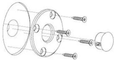
- Remove lateral plastic caps at the enclosure and keep it for further use. Unscrew shaft screws.
- Mount the wrinkle plates with the provided screws on the enclosure; the caps removed before can be used as a centering assistance.
- Push flight bracket from the rear onto the enclosure and screw it with the cone handles onto the enclosure.
- Make sure that the flight bracket is additionally secured against falling down during operation. For this the eye bolt mounted at the flight bracket should be used.
natural_image
Technical line drawing of a mechanical assembly with flanges and bolts (no text or symbols)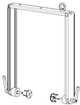
natural_image
Technical line drawing of a mechanical frame with two vertical supports and a central valve (no text or symbols)FB-VL122 D113111
natural_image
Line drawing of a rectangular industrial machine with a side panel and handle (no text or symbols)FB-VL 152
Flight bracket for VL 152.
The FB-VL 152 can be equipped for different assembly requirements in each case with PCL-M10, TC-02 or FB-TV.
Assembly instruction:
- Remove lateral plastic caps at the enclosure and keep it for further use. Unscrew shaft screws.
- Mount the wrinkle plates with the provided screws on the enclosure; the caps removed before can be used as a centering assistance.
- Push flight bracket from the rear onto the enclosure and screw it with the cone handles onto the enclosure.
- Make sure that the flight bracket is additionally secured against falling down during operation. For this the eye bolt mounted at the flight bracket should be used.
natural_image
Technical line drawing of a mechanical assembly with flanged components and threaded fasteners (no text or symbols)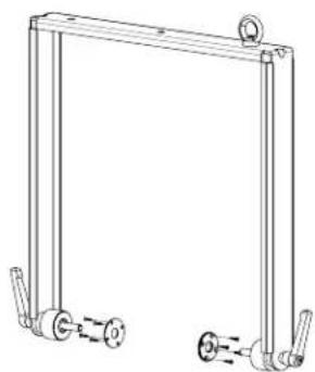
natural_image
Technical line drawing of a mechanical frame with two side supports and a central roller (no text or symbols)FB-VL152 D113112
natural_image
Line drawing of a rectangular industrial machine with a side-mounted handle and control panel (no text or symbols)FB-VL 212
Flight bracket for VL 212.
The FB-VL 212 can be equipped for different assembly requirements in each case with PCL-M10, TC-02 or FB-TV.
Assembly instruction:
- Remove lateral plastic caps at the enclosure and keep it for further use. Unscrew shaft screws.
- Mount the wrinkle plates with the provided screws on the enclosure; the caps removed before can be used as a centering assistance.
- Push flight bracket from the rear onto the enclosure and screw it with the cone handles onto the enclosure.
- Make sure that the flight bracket is additionally secured against falling down during operation. For this the eye bolt mounted at the flight bracket should be used.
natural_image
Technical line drawing of a mechanical assembly with flanged components and threaded fasteners (no text or symbols)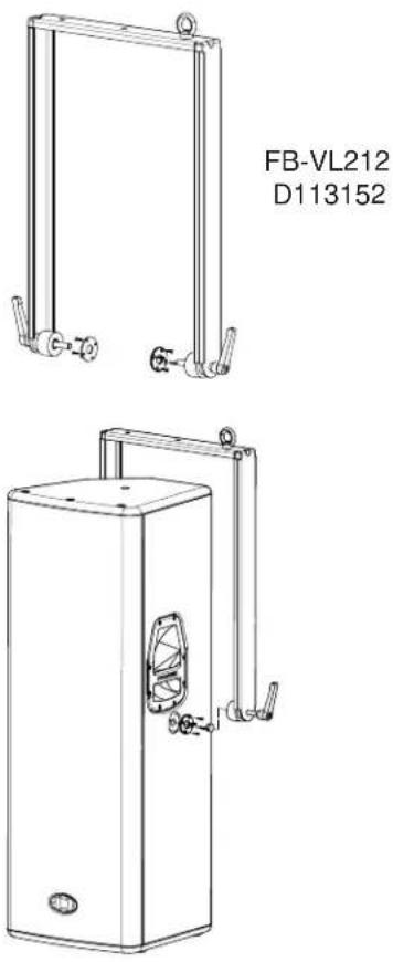
FB-CXM 15
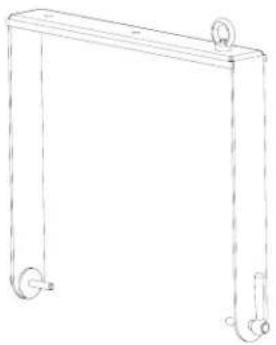
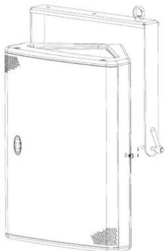
Flight bracket for CXM 15..
The FB-CXM 15 can be equipped for different assembly requirements in each case with PCL-M10, TC-02 or FB-TV.
Assembly instruction:
- Remove lateral screws (see fi g.) at the enclosure and keep it for further use.
- Push flight bracket onto the enclosure and screw it with the cone handles onto the enclosure.
- Make sure that the flight bracket is additionally secured against falling down during operation. For this the eye bolt mounted at the flight bracket should be used.
natural_image
Line drawing of a rectangular frame with two wheels and a central handle (no text or symbols)FB-CXM 15
D113299
natural_image
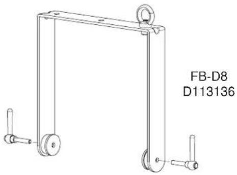
Line drawing of a rectangular industrial or storage unit with mounting bracket and side-mounted handle (no text or symbols)FB-D8
Flight bracket for D8.
The FB-D8 can be equipped for different assembly requirements in each case with PCL-M10, TC-02 or FB-TV.
Assembly instruction:
- Remove lateral plastic caps at the enclosure and keep it for further use.
- Push flight bracket from the rear onto the enclosure and screw it with the cone handles onto the enclosure.
- Make sure that the flight bracket is additionally secured against falling down during operation. For this the eye bolt mounted at the flight bracket should be used.
natural_image
Technical line drawing of a mechanical frame with two side handles and a circular top component (no text or symbols)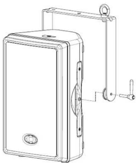
natural_image
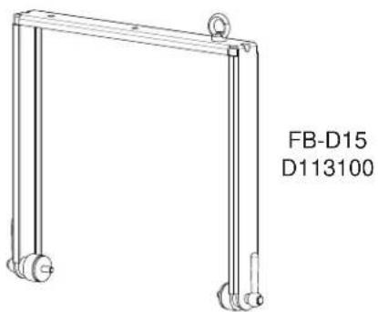
Technical line drawing of a mechanical device with mounting bracket and handle (no text or symbols)FB-D15
Flight bracket for D15-3.
The FB-D15 can be equipped for different assembly requirements in each case with PCL-M10, TC-02 or FB-TV.
Assembly instruction:
- Remove lateral plastic caps at the enclosure and keep it for further use.
- Push fl ight bracket from the rear onto the enclosure and screw it with the cone handles onto the enclosure.
- Make sure that the flight bracket is additionally secured against falling down during operation. For this the eye bolt mounted at the flight bracket should be used.
text_image
FB-D15 D113100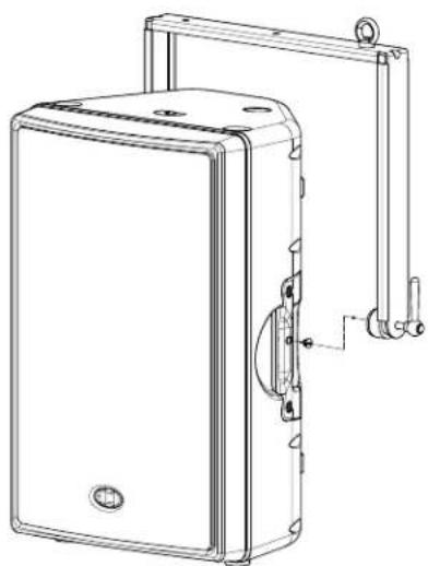
natural_image
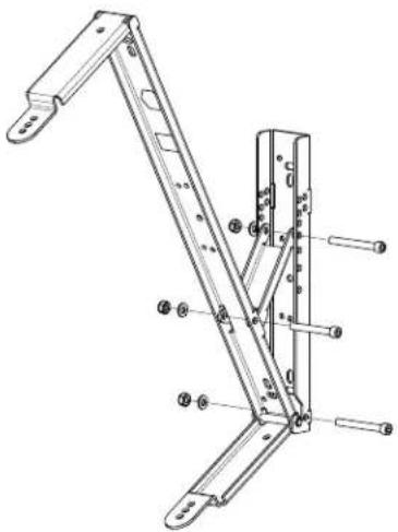
Technical line drawing of a wall-mounted device with mounting bracket and handle (no text or symbols)TMA (Tilt Mount Accessory)
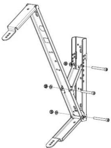
Wall mount for the wall mounting brackets MB...UMH. The inclination can be adjusted between 5° and 45° in 5° steps. An adjustment to the listeners direction with turn-in to the wall is realized additionally with the RMA.
Assembly instruction:
The relevant assembly instructions at ceilings, walls or trusses are to be considered absolutely.
- Fasten wall mount with suitable screws and pegs (10mm diameter) to the wall.
- Mount incliner.
- Install wall mounting bracket at the enclosure.
- Hang on enclosure with wall mounting bracket into the TMA on the bottom.
- Insert safety screw and fasten immediately.
- Adjust inclination angle and tight afterwards all screws firmly.

natural_image
Two black metal bracket components with mounting holes, one larger and one smaller, shown without any text or symbols.TMA (Tilt MountAccessory) D112815
text_image
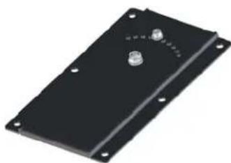
Technical diagram of a mechanical linkage assembly with numbered components for identificationRMA (Rotatable Mount Accessory)
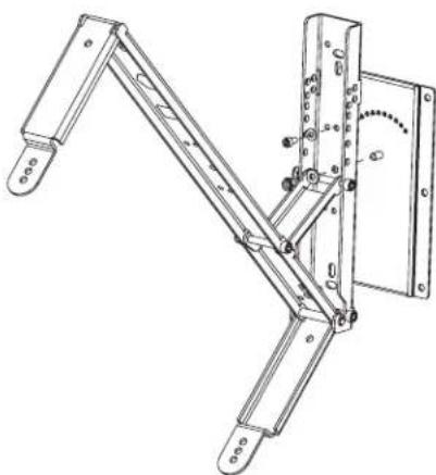
Rotor plate for the TMA and the wall mounting brackets MB...UMH for adjustment of inward turned boxes onto the listeners. Vertical rotation angle 45^ , adjustable in 5^ steps.
Assembly instruction:
The relevant assembly instructions at ceilings, walls or trusses are to be considered absolutely.
- Fasten RMA with 6 screws and pegs (10mm diameter) to the wall.
- Put on TMA onto the RMA and fasten with self-locking nut
- Adjust desired angle of rotation and fix it with stop screw. Tighten screws.
- Install wall mounting bracket at the enclosure.
- Set wall mounting bracket into the TMA and insert the safety screw immediately.
- Align enclosure.
- Tighten all screws
natural_image
Black rectangular electronic component with mounting holes and a small metallic knob (no text or symbols visible)RMA (Rotatable Mount Accessory)
D112807
natural_image
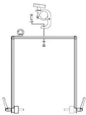
Technical line drawing of a mechanical linkage assembly with mounting feet and a curved dial (no text or symbols)TC-02 (Truss Clamp)
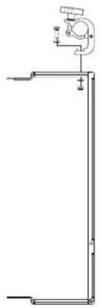
Clamp for the direct mounting of Flying Brackets (FB) and Mounting Brackets (MB) on trusses.
Assembly instruction:
- Mount the TC-02 on the FB using the associated M10 screw, lock washer, nut and fl at washer. The lock washer needs to be placed between M10 screw and Truss Clamp.
The fl at washer has to be installed between nut and bracket.
- Tighten screw and nut.
natural_image
Pure technical line drawing of a mechanical assembly without any text, numbers, or symbols
TC-02 (Truss Clamp)
D112808
natural_image
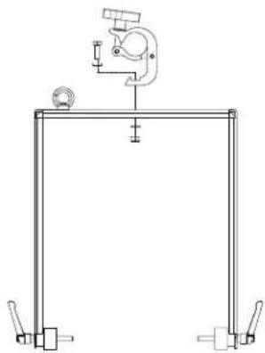
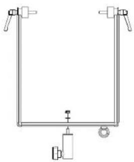
Pure mechanical diagram showing a frame structure with no text, numbers, or symbolsPCL-M10
Adapter with M10 threaded bolt for use with the FB... Flight brackets on speaker stands with 35mm fl angle diameter. The PCL-M10 can be used also for enclosures with M10 threaded inserts as speaker stand sleeve.
Assembly instruction:
- Fasten PCL-M10 with M10 nut and lock washer to the flight bracket.
- The lock washer must be attached between nut and flight bracket.
- Tighten nut.
natural_image
Pure mechanical diagram showing a U-shaped frame with clamps and a central valve (no text or symbols)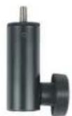
PCL-M10
D113116

natural_image
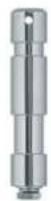
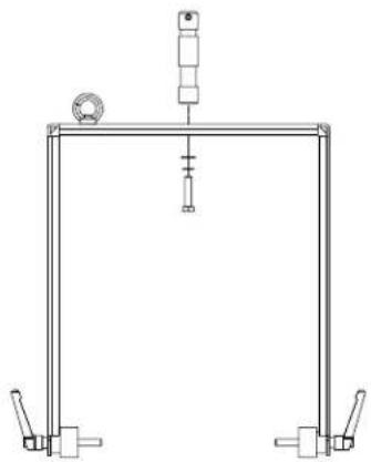
Pure technical line drawing of a rectangular device with a small circular component and a small mechanical component attached (no text or symbols)FB-TV (Flight Bracket TV stud)
TV stud for the FB -... fl ight brackets for use with suitable light tripods or with PM-TV on suitable speaker stand. With truss clamps (TC-TV) prepared for the insertion of TV studs.
Assembly instruction:
- Fasten FB-TV with M10 screw and lock washer to the flight bracket.
- The lock washer must be attached between screw and flight bracket.
- Tighten screw.
FB-TV (Flight Bracket TV stud)
D113142
natural_image
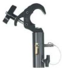
Pure mechanical diagram of a frame structure without any text, numbers, or symbolsTC-TV (Truss Clamp TV stud)
Clamp for trusses with insertion for TV studs (FB-TV).
Assembly instruction:
- Put TC-TV clamp onto the TV stud (FB-TV).
- Lead safety pin through the lockhole and secure it by bending the safety pin.
- Tighten the lock screw of the TC-TV.
natural_image
Close-up of a black mechanical clamp or clamp device with a handle and clamped parts (no visible text or symbols)TC-TV (Truss clamp TV stud)
D112941
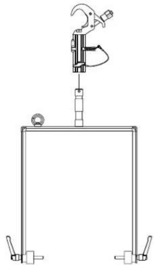
natural_image
Technical line drawing of a mechanical clamp device mounted on a frame, with no visible text or symbols.PM-TV (Pole Mount TV stud)
Adapter for the use of flight brackets with TV stud on stands such as K&M 213 (Koenig&Meyer) or models with same M10 threaded nut and same 35mm flange diameter (inside M10 threaded bolt).
Assembly instruction:
- Set PM-TV onto the high stand fl ange of the tripod and tighten it by turning.
- Insert TV stud FB-TV to the PM-TV adapter and secure with the locking bolt.
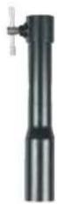
PM-TV (Pole Mount TV stud)
D112942
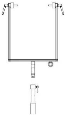
natural_image
Pure mechanical diagram of a U-shaped frame with vertical connectors and a central hanging component (no text or symbols)EBK-M10 (Eye Bolt Kit M10)
Eye bolt kit for fl ying the enclosure with chains or ropes.
Assembly instruction:
For safety reasons the suspension must be carried out at least at 3 threaded inserts in the enclosure. The relevant assembly instructions at ceilings, walls or trusses are to be considered absolutely.
- Remove the plastic covers of the necessary M10 threaded inserts at the enclosure.
- Unscrew the shaft screws from the threaded inserts.
- Screw in the eye bolts with thread locking compound and secure it from the outside with lock nuts against rotating.
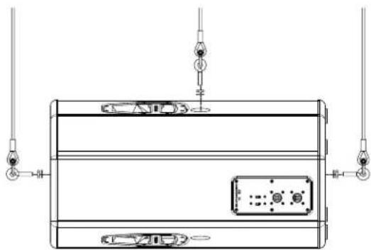
natural_image
Technical line drawing of a mechanical or electronic component with no visible text, numbers, or symbols.
natural_image
Three black plastic chain link components with circular ends, arranged on a white background (no text or symbols)EBK-M10 (Eye Bolt Kit M10)
D113155

natural_image
Technical line drawing of a mechanical or electrical enclosure with hanging connectors and internal components (no text or symbols)WMK-10 (Wall Mount Kit)
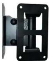
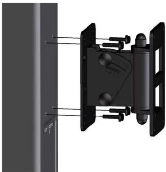
Wall mount for VL 62 and VL262 and other small enclosures up to 15kg. Universal adapter plate for standard 4-point mounting. Adjustable in direction and inclination. Possible vertical inclination angles up to 30°.
Assembly instruction:
The relevant assembly instructions at ceilings, walls or trusses are to be considered absolutely.
- Dismount tilt bracket with adapter from the swiveling bracket of the wall mount.
- Install wall mont with suitable mounting hardware at the wall.
- Fasten enclosure with the 4 attached screws to the adapter.
- Hang up adapter plate with tilt bracket into the swiveling bracket of the wall mount.
- Bolt the hanged up tilt bracket immediately with lock screw, lock washer and locknut with the swiveling bracket.
- Adjust desired inclination angle by fixing the upper screw connection at the tilt bracket.
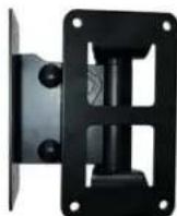
WMK-10 (Wall Mount Kit)
D113137
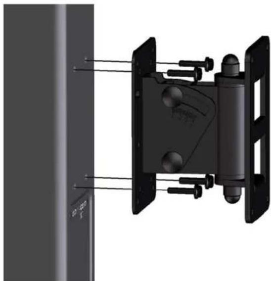
natural_image
3D mechanical assembly diagram showing a vertical panel connected to a black component with multiple bolts and mounting brackets (no text or symbols visible)ZERTIFIKAT
Bosch Communications Systems
Americas-Headquarters AmericasBosch
Security Systems, Inc.
12000 Portland Ave South,
Burnsville, MN 55337, USA
USA-Ph: 1-800-392-3497
Fax: 1-800-955-6831
Canada-Ph: 1-866-505-5551
Fax: 1-866-336-8467
Latin America—Ph: 1-952-887-5532
Fax: 1-952-736-4212
Europe, Middle-East & Africa
Headquarters EMEA
94315 Straubing, Germany
Phone +49 9421 706-0
Fax: +49 9421 706-265
France: EVI Audio France S.A.S
Phone: +33 1-6480-0090
Fax: +33 1-6006-5103
UK: Shuttlesound Ltd.
Phone: +44 208 646 7114
Fax: +44 208 254 5666
Middle East: Robert Bosch Middle East FZE
Tel. +97 14 2123300
Fax. +97 14 2123388
Asia & Pacific
Headquarters APR
Robert Bosch (SEA) Pte Ltd
38 C Jalan Pemimpin
Singapore 577180
Singapore/ ASEAN: Robert Bosch (SEA) Pte Ltd
Tel: +65 6319 0616
Fax: +65 6319 0620
Australia: Bosch Security Systems Pty Ltd
Tel: +61 2 9683 4752
Fax: +61 2 9890 5928
China: Telex EVI Audio (Shanghai) Co., Ltd.
Tel: +86 21 6317 2155
Fax: +86 21 6317 3025
India: Bosch Limited
Tel: +91 80 4176 8378
Fax: +91 80 4176 8263
Japan: EVI Audio Japan
Tel: +81 3 5316 5020
Fax: +81 3 5316 5030
Thailand: Robert Bosch Limited
Tel: +662 639 3111
Fax: +662 631 2030