
A 112A - Loudspeaker DYNACORD - Free user manual and instructions
Find the device manual for free A 112A DYNACORD in PDF.


| Product Type | Powered two-way full-range loudspeaker |
| Model | A 112A |
| Woofer | 1 x EVS-12K, 305 mm (12") |
| HF Driver | DH-1K, 39 mm (1.5") titanium diaphragm compression driver |
| Amplifier Type | Class D, dual-channel (bi-amping) |
| Maximum Amplifier Output (Peak) | 500 W |
| Amplifier Power RMS | 420 W |
| Maximum SPL (1 m, calculated) | 121 dB |
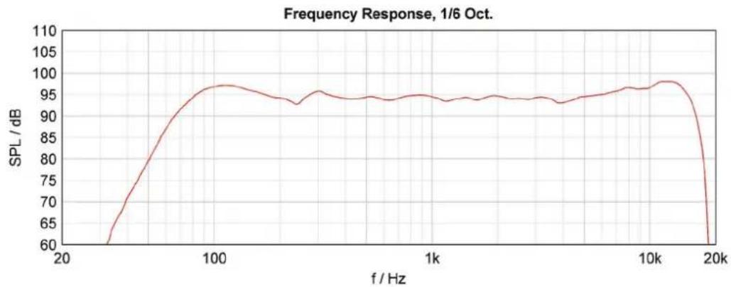
| Frequency Range (-10 dB) | 55 Hz – 17 kHz |
| Frequency Response (-3 dB) | 65 Hz – 16 kHz |
| Coverage Angle (H x V) | 90° x 50° |
| Crossover Frequency | 1.7 kHz |
| Digital Signal Processing | 28/56-Bit, 48 kHz, FIR filter technology |
| Audio Inputs | LINE 1: XLR/TRS combo; INPUT 2: XLR/TRS combo (switchable mic/line); AUX: Stereo RCA |
| Audio Output | LINK OUTPUT: XLR balanced (selectable LINE 1 or MIX) |
| Controls | Volume, INPUT 1 Level, INPUT 2 Level, SELECT (LINE 1/MIX), MAIN/MONITOR, FULL RANGE/LO-CUT, Power switch |
| Indicators | LIMIT LED (power amp limit), Power switch light |
| Power Requirement | 220-240 V AC / 100-120 V AC, 50-60 Hz, 0.6 A / 1.0 A |
| Safety Class | I (protective earth connection) |
| Enclosure Material | 15-mm multi-ply wood with black textured paint |
| Grille | 18-GA steel with black powder coat |
| Dimensions (W x H x D) | 607 mm x 362 mm x 340 mm |
| Net Weight | 16.8 kg |
| Shipping Weight | 21.9 kg |
| Handles | 1 |
| Operating Temperature Range | 0 °C to 40 °C |
| Included Accessories | Mains cord, Owner's manual, Warranty certificate |
| Optional Accessories | Dust cover SH-112A, speaker pole VPM 1500, speaker stand BS 35 |
| Cleaning | Clean only with a dry cloth |
| Warranty | Visit www.dynacord.com for warranty information |
Frequently Asked Questions - A 112A DYNACORD
User questions about A 112A DYNACORD
0 question about this device. Answer the ones you know or ask your own.
Ask a new question about this device
Download the instructions for your Loudspeaker in PDF format for free! Find your manual A 112A - DYNACORD and take your electronic device back in hand. On this page are published all the documents necessary for the use of your device. A 112A by DYNACORD.
USER MANUAL A 112A DYNACORD
natural_image
Two black audio/video speakers stacked vertically, no visible text or symbols on the device body.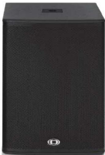
natural_image
Black audio amplifier speaker with visible grille and buttons (no text or symbols)A 112A | A 115A | A 118A
A-Line Powered Speakers
natural_image
Stylized logo of a D-shaped object enclosed in an oval frame (no text or symbols)DYNACORD
GERMAN ENGINEERING EXCELLENCE
CONTENTS
INTRODUCTION 5
Scope of Delivery, Unpacking and Inspection 5
Warranty 5
HF-Interference 5
INSTALLATION 6
Controls, Indicators and Connections 6
Power Amplifier and Cooling 8
Quickstart 8
APPENDIX / ANHANG 16
Specifications 16
Block Diagram 18
Dimensions 20
Setup Examples....21
INHALT
EINFÜHRUNG 11
IMPORTANT SAFETY INSTRUCTIONS
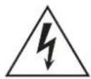
The lightning flash with arrowhead symbol, within an equilateral triangle is intended to alert the user to the presence of uninsulated "dangerous voltage" within the product's enclosure that may be of sufficient magnitude to constitute a risk of electric shock to persons.

The exclamation point within an equilateral triangle is intended to alert the user to the presence of important operating and maintenance (servicing) instructions in the literature accompanying the appliance.
-
Read these instructions.
-
Keep these instructions.
-
Heed all warnings.
-
Follow all instructions.
-
Do not use this apparatus near water.
-
Clean only with a dry cloth.
-
Do not cover any ventilation openings. Install in accordance with the manufacturer's instructions.
-
Do not install near heat sources such as radiators, heat registers, stoves, or other apparatus (including amplifiers) that produce heat.
-
Do not defeat the safety purpose of the polarized or the grounding-type plug. A polarized plug has two blades with one wider than the other. A grounding type plug has two blades and a third grounding prong. The wide blade or the third prong are provided for your safety. If the provided plug does not fit into your outlet, consult an electrician for replacement of the obsolete outlet.
-
Protect the power cord from being walked on or pinched particularly at plugs, convenience receptacles, and the point where they exit from the apparatus.
-
Only use attachments/accessories specified by the manufacturer.
-
Use only with the cart, tripod, bracket, or table specified by the manufacturer, or sold with the apparatus. When a cart is used, use caution when moving the cart/apparatus combination to avoid injury from tip-over.
-
Unplug this apparatus during lightning storms or when unused for a long period of time.
-
Refer all servicing to qualified service personnel. Servicing is required when the apparatus has been damaged in any way, such as power-supply cord or plug is damaged, liquid has been spilled or objects have fallen into the apparatus, the apparatus has been exposed to rain or moisture, does not operate normally, or has been dropped.
-
Do not expose this equipment to dripping or splashing and ensure that no objects filled with liquids, such as vases, are placed on the equipment.
-
To completely disconnect this equipment from the AC Mains, disconnect the power supply cord plug from the AC receptacle.
-
The mains plug of the power supply cord shall remain readily operable.
-
No naked flame sources, such as lighted candles, should be placed on the apparatus.
-
The product should be connected to a mains socket outlet with a protective earthing connection.

IMPORTANT SERVICE INSTRUCTIONS
CAUTION: These servicing instructions are for use by qualified personnel only. To reduce the risk of electric shock, do not perform any servicing other than that contained in the Operating Instructions unless you are qualified to do so. Refer all servicing to qualified service personnel.
-
Security regulations as stated in the EN 60065 (VDE 0860 / IEC 65) and the CSA E65 - 94 have to be obeyed when servicing the appliance.
-
Use of a mains separator transformer is mandatory during maintenance while the appliance is opened, needs to be operated and is connected to the mains.
-
Switch off the power before retrofitting any extensions, changing the mains voltage or the output voltage.
-
The minimum distance between parts carrying mains voltage and any accessible metal piece (metal enclosure), respectively between the mains poles has to be 3 mm and needs to be minded at all times. The minimum distance between parts carrying mains voltage and any switches or breakers that are not connected to the mains (secondary parts) has to be 6 mm and needs to be minded at all times.
-
Replacing special components that are marked in the circuit diagram using the security symbol (Note) is only permissible when using original parts.
-
Altering the circuitry without prior consent or advice is not legitimate.
-
Any work security regulations that are applicable at the locations where the appliance is being serviced have to be strictly obeyed. This applies also to any regulations about the work place itself.
-
All instructions concerning the handling of MOS-circuits have to be observed.
NOTE: SAFETY COMPONENT (MUST BE REPLACED BY ORIGINAL PART)

1 Introduction
The DYNACORD powered A-Line series includes three models: a 12-inch, two-way full-range; a 15-inch, two-way full-range; and a perfectly matching 18-inch subwoofer. All three models feature solid 15-mm plywood enclosures that combine durability with low weight. A high-quality black paint finish and steel grille offer road-ready ruggedness and a professional appearance. The full-range models are equipped with a 12-inch EVS-12K woofer (A 112A), a 15-inch EVS-15K (A 115A) and provide an 1.5" titanium diaphragm compression driver radiating into a 90 x 50-degree (H x V) high-frequency waveguide. Both of the cabinets provide an asymmetrical footprint with a 60-degree monitor angle allowing for alternative use as a powered floor monitor.
The onboard power modules of A 112A and A 115A combine lightweight Class-D dual-channel power amplifiers (biamping) with a total of 500 W dynamic peak power, along with the digital signal processing for crossover (24 dB/octave slope), EQ and advanced digital speaker protection. The linearization of transfer function in both cabinets is provided by state-of-the-art FIR filter technology.
The operating and connector panels are designed for intuitive operation and versatile connectivity. The 2-channel mixer section offers a XLR/TRS combo connector Line 1, stereo RCA sockets and a level control in the Input 1 channel, and a second XLR/TRS combo connector Line 2 which is switchable for microphone or line sensitivity in channel Input 2. For daisy-chaining to other devices, there is a XLR link output available which can be set to provide either the Line 1 or the mix signal.
In the Master section we find the overall Volume control, along with a switch for selecting the dedicated EQ setting for either Main or Monitor operation. A second switch activates a high-pass filter when using the full-range cabinets in combination with a powered subwoofer (A 118A).
The powered subwoofer A 118A features a similar power module with 400 W peak power, Master Volume control, a phase-inversion switch, a XLR/TRS combo input connector, and a XLR link output socket.
Setting up a small - yet very powerful - system turns out to be a piece of cake when combining with DYNACORD CMS mixing consoles (e.g. CMS 600-3). They are the perfect fit and offer a broad range of advanced features in concert sound quality.
1.1 Scope of Delivery, Unpacking and Inspection
• 1 Powered Speaker or Powered Subwoofer
• 1 Owner's Manual (this document)
• 1 M a i n s C o r d
• 1 Warranty Certificate including Safety Instructions
Carefully open the packaging and take out the cabinet. Inspect the cabinet's enclosure for damages that might have
occurred during transportation. Each cabinet is examined and tested in detail before leaving the manufacturing site to ensure that it arrives in perfect condition.
Please inform the transport company immediately if the cabinet shows any damage. Only the addressee can claim damages in transit. Keep the cardboard box and all packaging materials for inspection by the transport company. Keeping the cardboard box including all packing materials is recommended.
HINT: Only ship the cabinet in its original packaging.
Package the cabinet as ist was packaged by the manufacturer to guarantee optimum protection from transport damage.
1.2 Warranty
Visit www.dynacord.com for warranty information.
1.3 HF-Interference
This equipment has been tested and found to comply with the limits for a Class A digital device, pursuant to Part 15 of the FCC Rules. These limits are designed to provide reasonable protection against harmful interference in a residential installation. This equipment generates, uses, and can radiate radio frequency energy and, if not installed and used in accordance with the instructions, may cause harmful interference to radio communications. However, there is no guarantee that interference will not occur in a particular installation. If this equipment does cause harmful interference to radio or television reception, which can be determined by turning the equipment off and on, the user can try one or more of the following measures to correct the interference:
- Reorient or relocate the receiving antenna
- Increase the separation between the equipment and receiver
- Connect the equipment into an outlet on a different circuit than the receiver
- Consult the dealer or an experienced radio/TV technician for help
2 Installation
2.1 Controls, Indicators and Connections
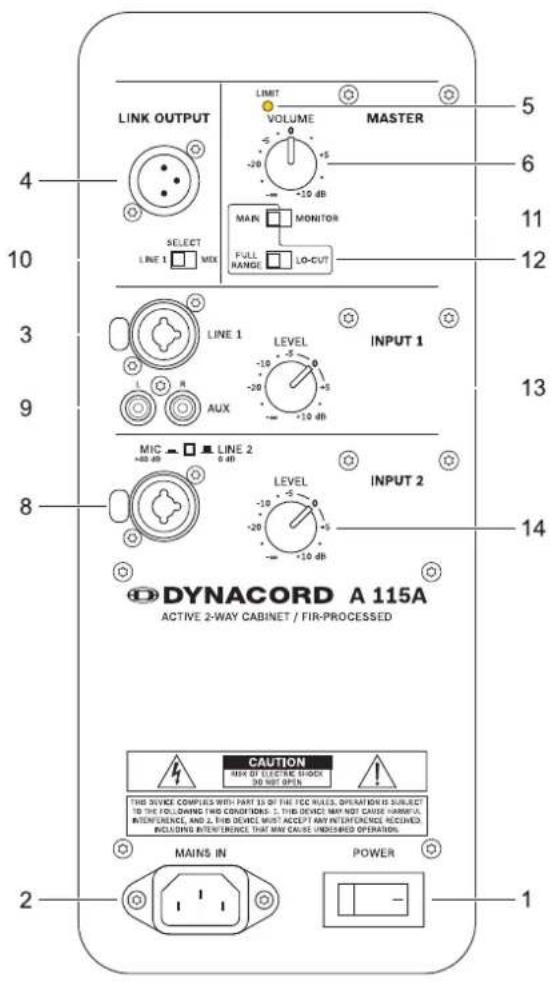
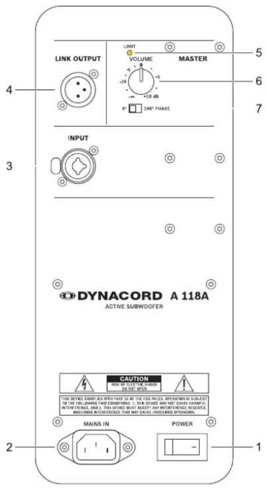
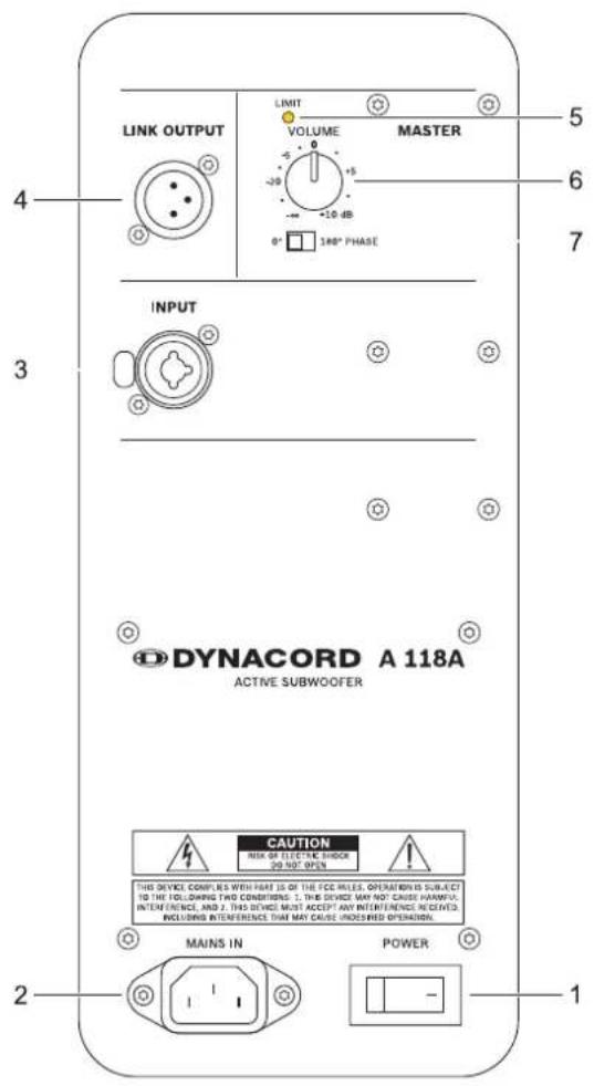
Number A 112A or A 115A A 118A
| 1 Mains switch (POWER) | ||
| 2 Mains connector (MAINS IN) | ||
| 3 Input connector for audio signal (A 112A or A 115A: LINE 1, A 118A: INPUT) | ||
| 4 Output connector forl audio signal (LINK OUTPUT) | ||
| 5 Limit indicator (LIMIT) | ||
| 6 Volume level control (VOLUME) | ||
| 7 - Polarity switch (0°/180° PHASE) | ||
| 8 | Input connector for audio signal (INPUT 2) with sensitivity selection switch (MIC/LINE 2) | - |
| 9 AUX connector for audio signal (AUX L/R) - | ||
| 10 Signal source selection switch (SELECT) | - | |
| 11 | Speaker mode selection switch (MAIN/MONITOR) | - |
| 12 | Selection switch for MAIN mode (FULL RANGE/LO-CUT) | - |
| 13 | INPUT 1 level control (LEVEL) | - |
| 14 | INPUT 2 level control (LEVEL) | - |
1 MAINS SWITCH (POWER)
POWER
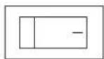
Mains switch for switching the unit's power on or off. The switch lights after turning the power on. If the switch does not light when powered on with the mains cord correctly connected and mains voltage present, please contact your local dealer.
2 MAINS CONNECTOR (MAINS IN)
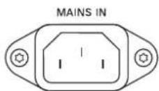
The device receives its power supply via the MAINS IN connector. Only the provided power cord may be used. Connect the device only to a mains network, which corresponds to the requirements indicated on the type plate.
3 INPUT CONNECTOR FOR AUDIO SIGNAL (LINE 1/INPUT)

Electronically balanced input for the connection of a line level signal source, such as mixer, signal processor, etc. Establishing a connection is possible via TRS or XLR-type plugs. Whenever possible, balanced signal feed is always preferable to guard against potential noise or HF-interference.
4 OUTPUT CONNECTOR FOR AUDIO SIGNAL (LINK OUTPUT)
LINK OUTPUT
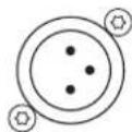
This output socket is for the connection of an additional powered loudspeaker or subwoofer. The output signal is electronically balanced with a maximum level of +18 dBu. Output impedance is 150 ohms.
For the A 112A or A 115A, the output signal is based on the selection made at the signal source selection switch SELECT.
5 LIMIT INDICATOR (LIMIT)

The LIMIT indicator signals the device is operating at the internal power amp's limit. Frequent blinking of the LED is acceptable, since the incorporated DSP clip limiter prevents distortion. Continuous lighting indicates that you have to be aware of degradation in the outputted sound. In that case, the input level has to be reduced. The LIMIT LED also lights if the output level is reduced because of high amplifier temperature.
6 VOLUME LEVEL CONTROL (VOLUME)
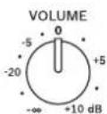
Level control for adjusting the volume of the loudspeaker. The level control affects the power amp's overall amplification. VOLUME control does not affect the level of the LINK OUTPUT connector.
7 POLARITY SWITCH (PHASE)

180° PHASE
Select 0^ if the signal polarity should not be inverted. Select 180^ to change the signal polarity by 180^ .
8 INPUT CONNECTOR FOR AUDIO SIGNAL (INPUT 2) WITH SENSITIVITY SELECTION SWITCH (MIC/LINE 2)
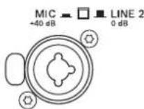
Electronically balanced input for the connection of a line level signal source (such as mixer, signal processor, etc.) or a dynamic microphone. Establishing a connection is possible via TRS or XLR-type plugs. Whenever possible, balanced signal feed is always preferable to guard against potential noise or HF-interference.
MIC/LINE 2 switch
Use the MIC/LINE 2 switch for switching between microphone (+40 dB) or line (0 dB) input sensitivity. When depressed, it activates a microphone preamp for use with dynamic microphones. A pen or paperclip is needed to depress the switch to MIC mode.
CAUTION: Do not plug a line level signal into INPUT 2 when MIC/LINE 2 is in the MIC position.
HINT: There is no phantom power available at the INPUT 2 connector, so powering a condenser microphone is not possible.
9 AUX CONNECTOR FOR AUDIO SIGNAL (AUX L/R)
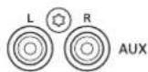
Stereo unbalanced RCA inputs AUX L/R for connecting sources such as CD players or MP3 players. Both RCA inputs are summed and can be controlled with IN-
PUT 1 LEVEL. The inputs can be used simultaneously with the XLR/TRS LINE 1 connector.
10 SIGNAL SOURCE SELECTION SWITCH (SELECT)
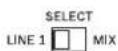
Use the SELECT switch for selecting the output signal of the LINK OUTPUT connector.
LINE 1
LINE 1 allows the pre-fader signal from LINE 1 input to pass to LINK OUTPUT (see illustration 2-1). The LINK OUTPUT signal level is not affected by the setting of the INPUT 1 LEVEL control. The signal from AUX L/R is not passed to LINK OUTPUT in this switch position.
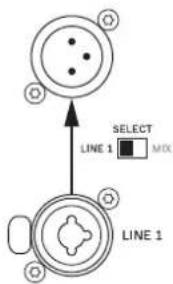
Illustration 2-1: Signal flow LINE 1
MIX
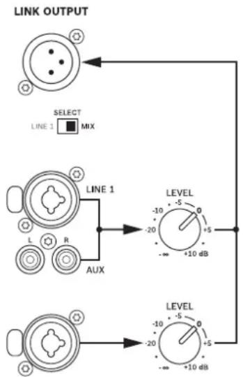
The post-fader audio signals of INPUT 1 (LINE 1 and AUX) and INPUT 2 are mixed and passed to LINK OUTPUT (see illustration 2-2). The ratio of the input signals changes when the level controls INPUT 1 and INPUT 2 are turned. MIX allows the loudspeaker to act as a basic two-channel mixer that can send the mix to another loudspeaker via the LINK OUTPUT connector.
flowchart
graph TD
    A["LINK OUTPUT"] --> B["SELECT LINE 3 MIX"]
    A --> C["LINE 1 AUX"]
    A --> D["LEVEL -5 0 +5 -10 dB"]
    A --> E["LEVEL -5 0 +5 -10 dB"]
Illustration 2-2: Signal flow MIX
11 SPEAKER MODE SELECTION SWITCH (MAIN/MONITOR)
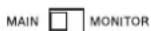
Select MONITOR to activate optimized signal processing for floor monitoring applications. MAIN works best for music
playback and applications that require enhanced bass and treble.
12 SELECTION SWITCH FOR MAIN MODE (FULL RANGE/LOCUT)
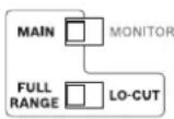
If the speaker is used as a full-range system, select FULL RANGE. If a subwoofer without a low-cut signal output is used, i.e. the identical audio signal is used for the A 112A/A 115A and the subwoofer,
select LO-CUT for activating the internal 100 Hz low-cut filter of the A 112A/A 115A. If the A 112A/A 115A is connected to the HI-OUT output of a subwoofer with integrated low-cut filter, select FULL RANGE to avoid having the two low-cut filters of the subwoofer and A 112A/A 115A in series.
The setting LO-CUT can also be used for delay applications, when a high bass level is not necessary.
13 INPUT 1 LEVEL CONTROL (LEVEL)
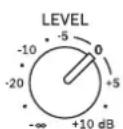
Level control for adjusting the amplification of the signal at the LINE 1 and AUX L/R input.
14 INPUT 2 LEVEL CONTROL (LEVEL)
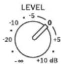
Level control for adjusting the amplification of the signal at the INPUT 2 input.
2.2 Power Amplifier and Cooling
This is a powered loudspeaker with a very high efficient amplifier module and as a result does not overheat. The temperature of the amplifier module is monitored. In the rare event it does get too hot, it will automatically shut down to protect itself. Once the temperature has returned to within the operating range, the amplifier will turn back on. This may happen when the speaker is operated in very high ambient temperatures and the enclosure is exposed to direct sunlight. Always ensure adequate cooling and appropriate shade to keep the ambient temperature around the speaker within the specified operating temperature range.
CAUTION: The rear panel of the amplifier module serves as a heat sink for the power amplifier. Certain parts may be hot during operation.
2.3 Quickstart
This section outlines setup and operation of two A 112A connected to a DYNACORD CMS mixer.
CAUTION: After system installation is complete, power on the mixing console first and position the master faders at the lowest setting before powering on the A 112A. Use the output faders to establish the desired volume setting. Otherwise, switching and power-on noise or the high level audio signal of an inadvertently playing audio source could result in high acoustic outputs, which in some cases might lead to hearing damage.
-
Place the A 112A, mounted on pole-mount stands to the left and to the right. The lower edges of the speaker systems should be approximately at a height of 1.8 meters to provide sufficient coverage and to prevent that listeners nearby are subject to extreme sound levels.
-
Using suitable XLR-type cables connect the Master Outputs of your mixing console, e.g. DYNACORD CMS 1000, to LINE 1 of the left or right A 112A. Position the master faders on the mixer to the minimum setting. Now, turn on the mixer.
-
Connect the A 112A to the mains outlet using the supplied mains cord. Plug the connector into the MAINS IN socket. Use the POWER switch to power-up the A 112A.
-
Set the LEVEL and VOLUME controls of the A 112A to 0 dB.
-
Select FULL RANGE and MAIN to operate the speakers as a main PA system.
-
Connect a audio source, e.g. CD player, to a line level input of the mixer, e.g. CMS 1000. Set all rotary con-
trols of the mixing console input channel to their center position. Adjust the input channel's 'Gain' control so that the Peak LED should not light at all or blink only once in a while.
-
Slowly raise channel fader and master faders on the mixing console to the desired positions - i.e. volume settings.
-
Your system is now ready for operation. Individual sound adjustments necessary can be made using the controls of the mixer's corresponding input channels.
-
Now have fun with your A 112A system!
-
After use, first switch off the A 112A and then the mixing console, so that distracting power-off noise will not occur. When using a DYNACORD CMS mixer, no power-off noise will be output from the 'Master Outputs'. This allows switching off the mixer first without a problem.
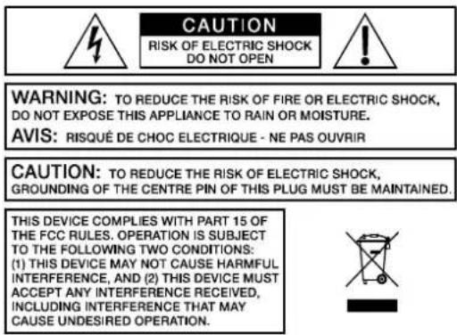
WARNING: TO REDUCE THE RISK OF FIRE OR ELECTRIC SHOCK, DO NOT EXPOSE THIS APPLIANCE TO RAIN OR MOISTURE.
AVIS: RISQUÉ DE CHOC ELECTRIQUE - NE PAS OUVRIR
CAUTION: TO REDUCE THE RISK OF ELECTRIC SHOCK, GROUNDING OF THE CENTRE PIN OF THIS PLUG MUST BE MAINTAINED.
THIS DEVICE COMPLIES WITH PART 15 OF THE FCC RULES. OPERATION IS SUBJECT TO THE FOLLOWING TWO CONDITIONS: (1) THIS DEVICE MAY NOT CAUSE HARMFUL INTERFERENCE, AND (2) THIS DEVICE MUST ACCEPT ANY INTERFERENCE RECEIVED, INCLUDING INTERFERENCE THAT MAY CAUSE UNDESIRED OPERATION.

| Property A 112A A 115A A 118A | |||
| Order No. 230 V: | F01U270188 (A112A-230V)120 V:F01U275161 (A112A-120V) | 230 V:F01U270189 (A115A-230V)120 V:F01U275163 (A115A-120V) | 230 V:F01U270190 (A118A-230V)120 V:F01U275164 (A118A-120V) |
| Cabinet Powered two-way full-range | speaker, 12" woofer, 1.5" compres-sion driver, vented design | Powered two-way full-range speaker, 15" woofer, 1.5" com-pression driver, vented design | Powered subwoofer 1 x 18", vented design |
| Maximum Amplifier Output Capability, IHF-A 500 W 400 W | |||
| Amplifier Power RMS 420 W 305 W | |||
| Output Stage Topology, amplifier Class D | |||
| Max. SPL 1 m / calc. 121 dB 124 dB 123 dB | |||
| Frequency Range (-10 dB) | 55 Hz to 17 kHz | 50 Hz to 17 kHz | 40 Hz to 130 Hz |
| Frequency Response (-3 dB) | 65 Hz to 16 kHz | 60 Hz to 16 kHz | 50 Hz to 100 Hz |
| Nominal Coverage Angle (Horizontal x Vertical) | 90° x 50° | Omnidirectional | |
| Audio Input (LINE 1 or MIC/LINE 2) | INPUT 1: XLR and 1/4" TRS combinationINPUT 2: XLR and 1/4" TRS combination | INPUT: XLR and 1/4" TRS combination | |
| Audio Input (AUX) | Stereo RCA, unbalanced | - | |
| Audio Output (LINK OUTPUT) | XLR, balanced | ||
| Digital Signal Processing | 28/56-Bit, 48 kHz | ||
| Crossover Frequency | 1.7 kHz | 100 Hz | |
| Switchable Phase (Polarity) | - | - | 0°, 180° |
| LF Transducer | 1 x EVS-12K, 305 mm (12"),F01U250937 | 1 x EVS-15K, 381 mm (15"),F01U250940 | 1 x EVS-18K, 457 mm (18"),F01U250964 |
| HF Transducer | DH-1K, 39 mm (1.5"), titanium diaphragm compression driver,F01U250928 | - | |
| Power Requirement | 230 V:220 to 240 V AC, 50 to 60 Hz, 0.6 A, IEC inlet120 V:100 to 120 V AC, 50 to 60 Hz, 1.0 A, IEC inlet | ||
| Safety Class | I | ||
| Operating Temperature Range | 0 °C to 40 °C | ||
| Dimensions (W x H x D) | 607 mm x 362 mm x 340 mm | 708 mm x 432 mm x 382 mm | 661 mm x 507 mm x 574 mm |
| Net Weight | 16.8 kg 22.5 kg 31.3 kg | ||
| Shipping Weight | 21.9 kg 28.4 kg 40.1 kg | ||
| Enclosure Material | 15-mm Multi-ply wood | ||
| Finish | Textured paint | ||
| Grille | 18-GA steel with black powder coat | ||
| Handles | 1 | 2 | 2 |
| Optional Accessories | |||
| Dust Cover | SH-112A: F01U270395 | SH-115A: F01U270396 | SH-118A: F01U270397 |
| VPM 1500, variable speaker pole | F01U141047 | ||
| BS 35, speaker stand | F01U141046 | ||
Device in rated condition, DSP flat, amplifier load 8 ohms, dual channel, mains voltage 230 V/50 Hz, unless otherwise specified.
Illustration 3-1: Frequency response of A 112A
line
| f / Hz | SPL / dB | | ------ | -------- | | 20 | 60 | | 100 | 97 | | 1k | 94 | | 10k | 98 | | 20k | 60 |Illustration 3-2: Frequency response of A 115A
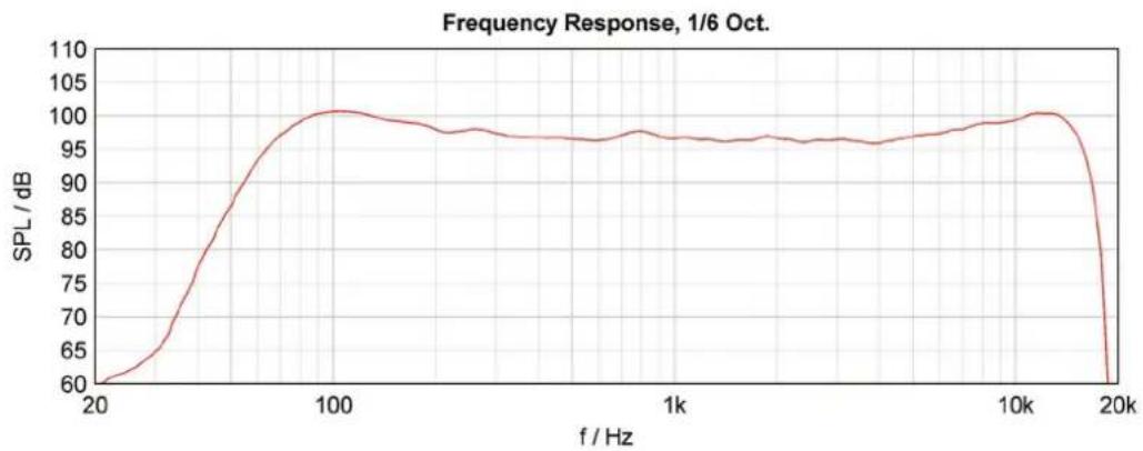
line
| f / Hz | SPL / dB | | ------ | -------- | | 20 | 60 | | 100 | 100 | | 1k | 97 | | 10k | 100 | | 20k | 60 |Illustration 3-3: Frequency response of A 118A
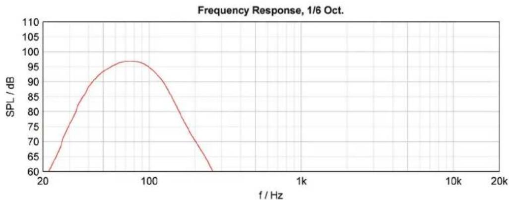
line
| f / Hz | SPL / dB | | ------ | -------- | | 20 | 60 | | 100 | 95 | | 1k | 70 | | 10k | 60 | | 20k | 60 |3.2 Block Diagram / Blockdiagramm
Illustration 3-4: Block diagram of A 112A or A 115A
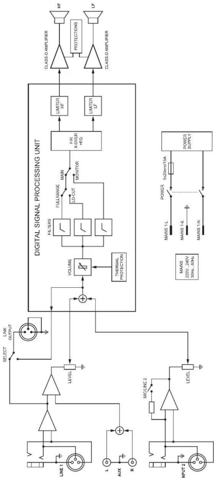
flowchart
graph TD
    A["INPUT 2"] --> B["MIC/LINE 2"]
    B --> C["LEVEL"]
    C --> D["VOLUME"]
    D --> E["FILTERS"]
    E --> F["FULLRANGE"]
    F --> G["LO-CUT"]
    G --> H["MONITOR"]
    H --> I["FIR X-OVER +EQ"]
    I --> J["LIMITER HF"]
    I --> K["LIMITER LF"]
    J --> L["CLASS-D AMPLIFIER"]
    K --> M["PROTECTIONS"]
    L --> N["HF"]
    M --> O["LF"]
    P["LINE 1"] --> Q["Select"]
    Q --> R["LINK OUTPUT"]
    S["THERMAL PROTECTION"] --> D
    T["POWER SUPPLY"] --> U["5x20mm/T5A"]
    V["MAINS 220V...240V 50Hz...60Hz"] --> W["MAINS 1-L"]
    V --> X["MAINS 1-E"]
    V --> Y["MAINS 1-N"]
Illustration 3-5: Block diagram of A 118A
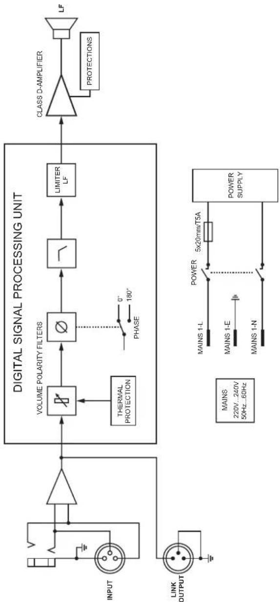
flowchart
graph LR
    A["INPUT"] --> B["Δ"]
    B --> C["VOLUME POLARITY FILTERS"]
    C --> D["∅"]
    D --> E["LIMITER LF"]
    E --> F["CLASS D-AMPLIFIER"]
    F --> G["LF"]
    H["LINK OUTPUT"] --> I["θ"]
    I --> J["THERMAL PROTECTION"]
    J --> C
    K["MAINS 220V...240V 50Hz...60Hz"] --> L["POWER 5x20mm/T5A"]
    L --> M["POWER SUPPLY"]
    N["PHASE 0° 180°"] -.-> D
3.3 Dimensions / Abmessungen
A 112A
![362mm [14.25"] 298mm [11.74"] 175mm [6.91"] 30" 270mm [10.63"] 340mm [13.41"] 73mm [2.88"] 235mm [9.26"]](/content/2026/05/845101/images/b74f4464b38f920ea3ddd3897124d2c2f4afa69a5f41dd0f173c4ed9e52ef5be.jpg)
BOTTOM
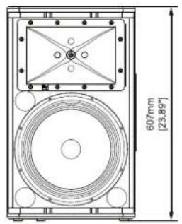
natural_image
Technical line drawing of a speaker or audio device with circular components and a central rectangular component (no text or symbols)FRONT
![173mm [6.81°] 300mm [11.82°]](/content/2026/05/845101/images/41744976a48aa22c7ae2ad6343488ddcf2896ad9ff584d3a9cacf00878fb8adc.jpg)
RIGHT
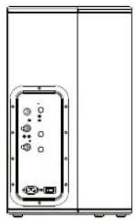
natural_image
Front view of a white cabinet with internal components and indicator lights (no text or symbols visible)REAR
A 115A
![432mm [17.02°] 368mm [14.49°] 199mm [7.84°] 30° 86mm [3.35°] 270mm [10.63°] 300mm [12.13°] 382mm [15.05°]](/content/2026/05/845101/images/63bdc442da687d0dc85438d81fac23bc067473005ae10a6c27bb4f2041c3ea55.jpg)
BOTTOM
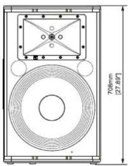
natural_image
Technical line drawing of a speaker or audio device with a 700mm height and 27.89" width dimension (no text or symbols on the diagram itself)FRONT
![213mm [8.39°] 354mm [13.82°]](/content/2026/05/845101/images/99d676bb7a11dcda3c6a8471412d26266aaaf3ec35346ff01d5774d4e9e48d85.jpg)
RIGHT
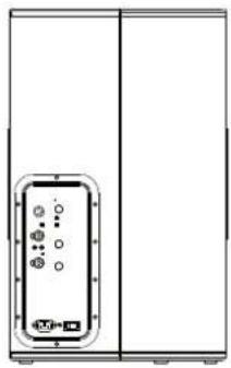
natural_image
Front view of a cabinet or enclosure with a central display unit and circular indicators (no text or symbols visible)REAR
A 118
![286mm [11.26°] 574mm [22.60°] 507mm [19.98°]](/content/2026/05/845101/images/890b8b259775da968ad7ca01860218250e493d3d29a4c8d4f0aab0b6226b400a.jpg)
TOP
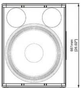
natural_image
Technical drawing of a speaker grille with three circular cutouts and a 60mm height dimension label (no text or symbols beyond measurement)FRONT
![267mm [11.3"] 327mm [12.88]](/content/2026/05/845101/images/78540629986c05f58a2269f3446f8853b7d2059fb2b8c66948be085fb972fb3c.jpg)
RIGHT
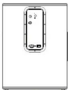
natural_image
Front view of a white electronic device with a black control panel and indicator lights (no text or symbols visible)REAR
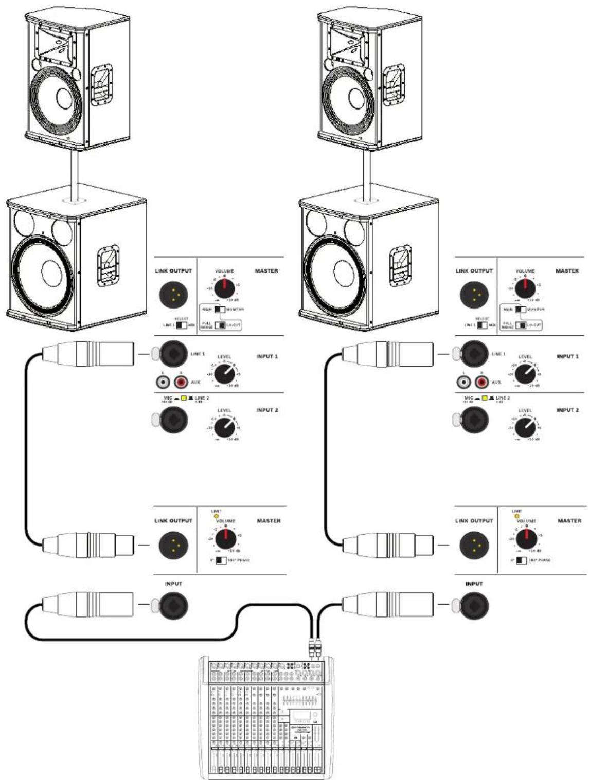
FULL-RANGE + SUBWOOFER CONFIGURATION
flowchart
graph TD
    A["Speaker 1"] --> B["LINK OUTPUT"]
    A --> C["VOLUME"]
    A --> D["MAIN"]
    E["Speaker 2"] --> F["LINK OUTPUT"]
    E --> G["VOLUME"]
    E --> H["MAIN"]
    I["Speaker 3"] --> J["LINK OUTPUT"]
    I --> K["VOLUME"]
    I --> L["MAIN"]
    M["Speaker 4"] --> N["LINK OUTPUT"]
    M --> O["VOLUME"]
    M --> P["MAIN"]
    Q["Speaker 5"] --> R["LINK OUTPUT"]
    Q --> S["VOLUME"]
    Q --> T["MAIN"]
    U["Speaker 6"] --> V["LINK OUTPUT"]
    U --> W["VOLUME"]
    U --> X["MAIN"]
    Y["Speaker 7"] --> Z["LINK OUTPUT"]
    Y --> AA["VOLUME"]
    Y --> AB["MAIN"]
    AC["Speaker 8"] --> AD["LINK OUTPUT"]
    AC --> AE["VOLUME"]
    AC --> AF["MAIN"]
Illustration 3-6: Stacking full-range systems with subwoofers (Dual A 112A or A 115A with LO-CUT setting selected, dual A 118A subwoofers)
DAISY-CHAIN CONFIGURATION
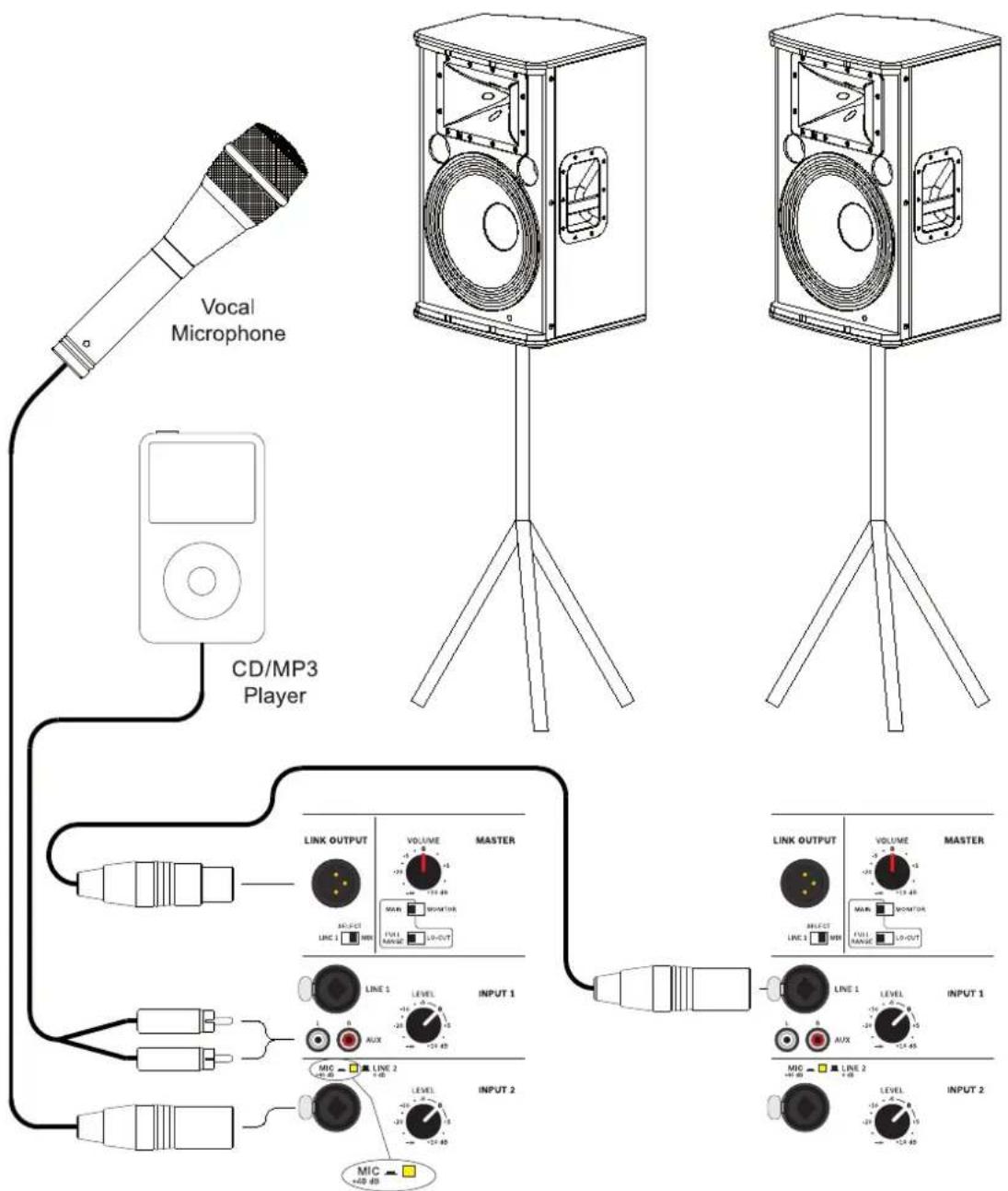
Illustration 3-7: Daisy-chaining full-range systems (dual A 112A or A 115A)
MONITOR CONFIGURATION
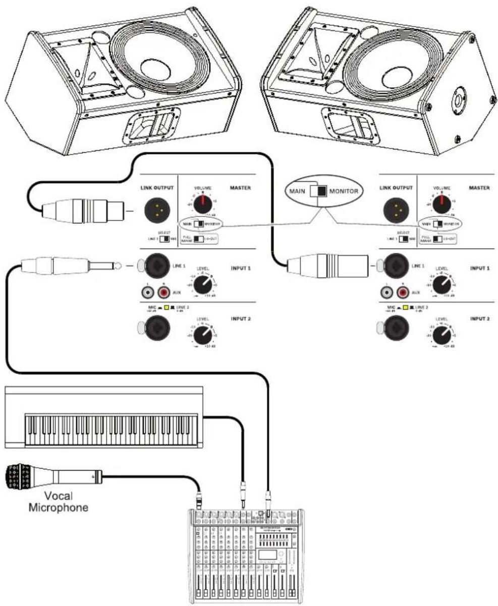
Illustration 3-8: Using full-range systems as Monitors (Dual A 112A or A 115A with MONITOR setting selected)

DYNACORD
12000 Portland Avenue South, Burnsville, MN 55337, USA
Phone: +1 952/844-4051, Fax: +1 952/884-0043
www.dynacord.com
© Bosch Communications Systems
10/2012
Part Number F01U270188 Vs 02
Europe, Africa, and Middle East only. For customer orders, contact Customer Service at:
+49 9421-706 0 Fax: +49 9421-706 265
Asia & Pacific only. For customer orders, contact Customer Service at:
+65 6571 2534 Fax: +65 6571 2699
For technical assistance, contact Technical Support at: +49 9421-706 0
Specifications subject to change without notice.

- CONTENTS
- INHALT
- IMPORTANT SAFETY INSTRUCTIONS
- IMPORTANT SERVICE INSTRUCTIONS
- Introduction
- Scope of Delivery, Unpacking and Inspection
- HINT: Only ship the cabinet in its original packaging.
- Warranty
- HF-Interference
- Installation
- Controls, Indicators and Connections
- MAINS SWITCH (POWER)
- MAINS CONNECTOR (MAINS IN)
- INPUT CONNECTOR FOR AUDIO SIGNAL (LINE 1/INPUT)
- OUTPUT CONNECTOR FOR AUDIO SIGNAL (LINK OUTPUT)
- LIMIT INDICATOR (LIMIT)
- VOLUME LEVEL CONTROL (VOLUME)
- POLARITY SWITCH (PHASE)
- INPUT CONNECTOR FOR AUDIO SIGNAL (INPUT 2) WITH SENSITIVITY SELECTION SWITCH (MIC/LINE 2)
- MIC/LINE 2 switch
- CAUTION: Do not plug a line level signal into INPUT 2 when MIC/LINE 2 is in the MIC position.
- HINT: There is no phantom power available at the INPUT 2 connector, so powering a condenser microphone is not possible.
- AUX CONNECTOR FOR AUDIO SIGNAL (AUX L/R)
- SIGNAL SOURCE SELECTION SWITCH (SELECT)
- LINE 1
- MIX
- SPEAKER MODE SELECTION SWITCH (MAIN/MONITOR)
- SELECTION SWITCH FOR MAIN MODE (FULL RANGE/LOCUT)
- INPUT 1 LEVEL CONTROL (LEVEL)
- INPUT 2 LEVEL CONTROL (LEVEL)
- Power Amplifier and Cooling
- Quickstart
- Block Diagram / Blockdiagramm
- Dimensions / Abmessungen
- DYNACORD
Brand : DYNACORD
Model : A 112A
Category : Loudspeaker