
V600:2 - Receiver DYNACORD - Free user manual and instructions
Find the device manual for free V600:2 DYNACORD in PDF.


| Product Type | Professional Audio Receiver |
| Brand | Dynacord |
| Model | V600:2 |
| Dimensions (H x W x D) | 88 x 483 x 350 mm (2U rackmount) |
| Weight | Approximately 12 kg |
| Power Supply | AC 100-240 V, 50/60 Hz, 600 VA max |
| Output Power (RMS) | 2 x 300 W @ 8 ohms, 2 x 500 W @ 4 ohms |
| Frequency Response | 20 Hz - 20 kHz, ±0.5 dB |
| Total Harmonic Distortion | < 0.05% at rated power |
| Inputs | 2 x XLR/TRS combo, 2 x RCA |
| Outputs | 2 x Speakon, 2 x Binding posts |
| Cooling | Variable speed fan, front-to-rear airflow |
| Protection Features | Short circuit, thermal, DC, over/under voltage |
| Controls | Independent level controls per channel, power switch |
| Indicators | Signal, clip, protect, power LEDs per channel |
| Operating Temperature | 0°C to 40°C |
| Humidity | 0% to 90% non-condensing |
| Maintenance | Clean with dry cloth; ensure ventilation; no user-serviceable parts inside |
| Safety Certifications | CE, UL, RoHS compliant |
| Spare Parts & Repairability | Contact authorized Dynacord service centers; some modules replaceable |
| Package Contents | Unit, power cord, quick start guide, warranty card |
Frequently Asked Questions - V600:2 DYNACORD
User questions about V600:2 DYNACORD
0 question about this device. Answer the ones you know or ask your own.
Ask a new question about this device
Download the instructions for your Receiver in PDF format for free! Find your manual V600:2 - DYNACORD and take your electronic device back in hand. On this page are published all the documents necessary for the use of your device. V600:2 by DYNACORD.
USER MANUAL V600:2 DYNACORD
| 1 | Important product information 4 | |
| 1.1 Safety Information 4 | ||
| 1.2 Disposal instructions 5 | ||
| 1.3 Class B Notice for FCC and ICES 003 5 | ||
| 2 | About this manual 6 | |
| 2.1 Digital document 6 | ||
| 2.2 Intended audience 6 | ||
| 2.3 Copyright notice 6 | ||
| 2.4 Trademarks 6 | ||
| 2.5 Notice of liability 6 | ||
| 2.6 Short information 7 | ||
| 2.7 Document history 7 | ||
| 3 | Product introduction 8 | |
| 3.1 Features and functions 9 | ||
| 4 | General installation procedures 10 | |
| 4.1 Unpacking 10 | ||
| 4.2 Parts included | 10 | |
| 4.3 Dimensions | 11 | |
| 4.4 Mounting and ventilation | 13 | |
| 4.5 Fan cooling | 22 | |
| 4.6 Mains operation and resulting temperature | 23 | |
| 5 | Installation | 25 |
| 5.1 Indicators, controls and settings | 25 | |
| 5.1.1 | Set the output mode (AMP MODE) | 27 |
| 5.1.2 | Set the input routing (DUAL / PARALLEL / IN1 to ALL) | 28 |
| 5.1.3 | Set the loudspeaker parameters (FILTER) | 29 |
| 5.1.4 | Set the energy safe option (APD) | 30 |
| 5.1.5 | ecoRAIL | 30 |
| 5.2 Connections | 31 | |
| 5.2.1 | Audio inputs | 31 |
| 5.2.2 | Line input RJ45 | 33 |
| 5.2.3 | Power outputs | 34 |
| 5.2.4 | Ready/Fault relay | 35 |
| 5.2.5 | Remote on | 36 |
| 5.2.6 | Mains power | 36 |
| 6 | Operation after installation | 37 |
| 6.1 Power on | 37 | |
| 6.2 Input level control | 37 | |
| 7 | Troubleshooting | 38 |
| 8 | Maintenance | 41 |
| 9 | Technical data | 42 |
| 10 | V600:4 Block diagram | 48 |
| 11 | V600:2 Block diagram | 49 |
| 12 | Support and academy | 50 |
1 Important product information
1.1 Safety Information
- Read and keep these safety instructions. Follow all instructions and heed all warnings.
- Download the latest version of the applicable installation manual from www.dynacord.com for installation instructions.

Information
Refer to the Installation Manual for instructions.
- Follow all installation instructions and observe the following alert signs:

Notice! Containing additional information. Usually, not observing a notice does not result in damage to the equipment or personal injuries.

Caution! The equipment or the property can be damaged, or persons can be injured if the alert is not observed.

Warning! Risk of electric shock.
- System installation and servicing by qualified personnel only, in accordance with applicable local codes. No user-serviceable parts inside.
- System installation for emergency sound (except for call stations and call station extensions) in a Restricted Access Area only. Children may not get access to the system.
- For rack-mounting of system devices, make sure that the equipment rack is of suitable quality to support the weight of the devices. Use caution when moving a rack to avoid injury from tip over.
- The apparatus shall not be exposed to dripping or splashing and no objects filled with liquids, such as vases, shall be placed on the apparatus.

Warning! To reduce the risk of fire and electric shock, do not expose this apparatus to rain or moisture.
- Mains powered equipment shall be connected to a mains power outlet socket with a protective earthing connection. An external, readily operable, mains plug or all-pole mains switch shall be installed.
- Only replace the mains fuse of an apparatus with a fuse of the same type.
- The protective ground connection of an apparatus shall be connected to protective ground before the apparatus is connected to a power supply.
- This unit has an autoranging input circuitry suitable for 100-240 Vac.
- Amplifier outputs marked with ⚠ may carry audio output voltages up to 120 V_RMS . Touching uninsulated terminals or wiring may result in an unpleasant sensation. Amplifier outputs marked with ⚠ or ⚠ may carry audio output voltages above 120 V_RMS . It requires a skilled person to strip and connect the loudspeaker wires in such a way that the naked conductors are inaccessible.
- To prevent hearing damage do not listen at high volume levels for long periods.
1.2 Disposal instructions
Old electrical and electronic appliances.
Electrical or electronic devices that are no longer serviceable must be collected separately and sent for environmentally compatible recycling (in accordance with the European Waste Electrical and Electronic Equipment Directive).
To dispose of old electrical or electronic devices, you should use the return and collection systems put in place in the country concerned.
1.3 Class B Notice for FCC and ICES 003
This equipment has been tested and found to comply with the limits for a Class B digital device, pursuant to part 15 of the FCC Rules and Canadian ICES-003 requirements. These limits are designed to provide reasonable protection against harmful interference in a residential installation. This equipment generates, uses and can radiate radio frequency energy and, if not installed and used in accordance with the instructions, may cause harmful interference to radio communications. However, there is no guarantee that interference will not occur in a particular installation. If this equipment does cause harmful interference to radio or television reception, which can be determined by turning the equipment off and on, the user is encouraged to try to correct the interference by one or more of the following measures:
- Reorient or relocate the receiving antenna.
- Increase the separation between the equipment and receiver.
- Connect the equipment into an outlet on a circuit different from that to which the receiver is connected.
- Consult the dealer or an experienced radio/TV technician for help.
2 About this manual
The purpose of this manual is to provide information required for installing, configuring, operating and maintaining these products.
Read through this manual to familiarize yourself with the safety information, features, and applications before you use it.
2.1 Digital document
This manual is available as a digital document in the Adobe Portable Document Format (PDF).
You can find information about Dynacord products on the product related information at www.dynacord.com.
2.2 Intended audience
This manual is intended for everyone who is authorized to install and use these products.
2.3 Copyright notice
Unless otherwise indicated, this publication is the copyright of Dynacord. All rights are reserved.
2.4 Trademarks
Throughout this document trademark names may have been used. Rather than put a trademark symbol in every occurrence of a trademark name, Dynacord states that the names are used only in an editorial fashion and to the benefit of the trademark owner with no intention of infringement of the trademark.
2.5 Notice of liability
While every effort has been taken to ensure the accuracy of this document, neither Dynacord nor any of its official representatives shall have any liability to any person or entity with respect to any liability, loss or damage caused or alleged to be caused directly or indirectly by the information contained in this document.
Dynacord reserves the right to make changes to features and specifications at any time without prior notification in the interest of ongoing product development and improvement.
2.6 Short information
The following table lists products in a family, with CTN (Commercial Type Number) and identifying product name DESCRIPTION.
| CTN Description | |
| V600:4-EU Power amplifier, 600 W, 4 channel, EU | |
| V600:2-EU Power amplifier, 600 W, 2 channel, EU | |
| V600:4-US Power amplifier, 600 W, 4 channel, US | |
| V600:2-US Power amplifier, 600 W, 2 channel, US | |
| V600:4-CN Power amplifier, 600 W, 4 channel, CN | |
| V600:2-CN Power amplifier, 600 W, 2 channel, CN | |
2.7 Document history
| Release date Documentation version Reason | |
| 2022.02.01 V01 Release | |
| 2023.09.01 V02 Addition of V600:2 |
3 Product introduction
The V series power amplifiers are ideally suited to background music and clear voice announcement applications such as:
- Bars and restaurants
- Retail outlets
- Education
- Houses of worship
- Museums and galleries
- Transport hubs
- Conference centers
The V600:4 is a 600 W power amplifier with powerTANK technology that flexibly delivers the total power over its 4 channels.

The V600:2 is a 600 W power amplifier with powerTANK technology that flexibly delivers the total power over its 2 channels.
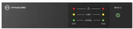
3.1 Features and functions
- 4-channel amplifier (V600:4) / 2-channel (V600:2) amplifier with a total powerTANK capacity of 600 W.
powerTANK is a reservoir of available amplification power that is deployed flexibly across all amplifier channels. There is no need to set up the powerTANK as it adapts to the requirements of each zone or output without extra manual configuration of each individual channel.
- Variable Load Drive (VLD) providing the same power into 4 , 8 , 70V or 100V . Variable Load Drive (VLD) ensures that the powerTANK capacity is utilized efficiently, providing consistent power to any channel with different loads.
- dualCOOL convection cooling with additional intelligent fan in case of extreme thermal conditions
The dualCOOL thermal design means that the amplifier typically operates as a convection cooled amplifier, but in extreme thermal conditions the amplifier is also equipped with an intelligent multi-speed fan to ensure maximum performance and reliability in any application.
- ecoRAIL and APD deliver significant reduction in power consumption ecoRAIL's power consumption is similar to a regular standby level, yet ecoRAIL still produces audio output suitable for background music levels, and the Auto Power Down (APD) mode can be engaged to further reduce power consumption to less than a watt when there is no signal present for extended periods.
- Line input single cable solution for easy installation
The single cable installation feature is compatible with AES72-1E (RJ45 connectors) wired devices. This solution provides easy installation for all four channels of the V600:4 / both channels of the V600:2 without needing to wire all the connections individually.
- Advanced Protection features and PFC to ensure reliability
Equipped with a PFC power supply and protection features usually reserved for the professional power amplifiers, means that the amplifier resists complete shutdown situations and will always perform at its best under all conditions.
4 General installation procedures
Before starting installation, ensure the following:
- You make use of manufacturer specified installation materials.
- No liquids can spill into or on the products.
- Installation is in a clean environment free of dust.
- The ventilation airflow of the 19" units is not obstructed.
- There is a mains power outlet of sufficient rating close to the intended location of the products.
- Sufficient free space and access at the rear of the 19" units for connectors and wiring.
4.1 Unpacking
The products should be unpacked and handled with care. If an item appears to be damaged, notify the shipper immediately. If any items are missing, notify your Dynacord representative.
The original packaging is the safest container in which to transport products and can also be used to return products for service, if necessary.
4.2 Parts included
| V600:4 V600:2 Component | ||
| 1 1 Power amplifier | ||
| 1 1 Mains cord | ||
| 1 1 Euroblock remote connector 5-pole | ||
| 2 1 Euroblock input connector 6-pole | ||
| 2 1 Euroblock output connector 4-pole | ||
| 4 4 Rubber feet | ||
| 2 N/A 19"-rack mounting brackets (pre-mounted) | ||
| N/A 1 M3 screw | ||
| N/A 2 Short rack ears | ||
| N/A 1 Long rack ear | ||
| N/A 1 Connection plate | ||
| 1 1 Quick Installation Guide | ||
| 1 1 Safety information | ||
4.3 Dimensions
V600:4
scatter
| x | y | |---|---| | 0.1 | 0.9 | | 0.2 | 0.85 | | 0.3 | 0.8 | | 0.4 | 0.75 | | 0.5 | 0.7 | | 0.6 | 0.65 | | 0.7 | 0.6 | | 0.8 | 0.55 | | 0.9 | 0.5 | | 1.0 | 0.45 | | 1.1 | 0.4 | | 1.2 | 0.35 | | 1.3 | 0.3 | | 1.4 | 0.25 | | 1.5 | 0.2 | | 1.6 | 0.15 | | 1.7 | 0.1 | | 1.8 | 0.05 | | 1.9 | 0.0 | | 2.0 | -0.05 | | 2.1 | -0.1 | | 2.2 | -0.15 | | 2.3 | -0.2 | | 2.4 | -0.25 | | 2.5 | -0.3 | | 2.6 | -0.35 | | 2.7 | -0.4 | | 2.8 | -0.45 | | 2.9 | -0.5 | | 3.0 | -0.55 | | 3.1 | -0.6 | | 3.2 | -0.65 | | 3.3 | -0.7 | | 3.4 | -0.75 | | 3.5 | -0.8 | | 3.6 | -0.85 | | 3.7 | -0.9 | | 3.8 | -0.95 | | 3.9 | -1.0 | | 4.0 | -1.05 | | 4.1 | -1.1 | | 4.2 | -1.15 | | 4.3 | -1.2 | | 4.4 | -1.25 | | 4.5 | -1.3 | | 4.6 | -1.35 | | 4.7 | -1.4 | | 4.8 | -1.45 | | 4.9 | -1.5 | | 5.0 | -1.55 | | 5.1 | -1.6 | | 5.2 | -1.65 | | 5.3 | -1.7 | | 5.4 | -1.75 | | 5.5 | -1.8 | | 5.6 | -1.85 | | 5.7 | -1.9 | | 5.8 | -1.95 | | 5.9 | -2.0 | | 6.0 | -2.05 | | 6.1 | -2.1 | | 6.2 | -2.15 | | 6.3 | -2.2 | | 6.4 | -2.25 | | 6.5 | -2.3 | | 6.6 | -2.35 | | 6.7 | -2.4 | | 6.8 | -2.45 | | 6.9 | -2.5 | | 7.0 | -2.55 | | 7.1 | -2.6 | | 7.2 | -2.65 | | 7.3 | -2.7 | | 7.4 | -2.75 | | 7.5 | -2.8 | | 7.6 | -2.85 | | 7.7 | -2.9 | | 7.8 | -2.95 | | 7.9 | -3.0 | | 8.0 | -3.05 | | 8.1 | -3.1 | | 8.2 | -3.15 | | 8.3 | -3.2 | | 8.4 | -3.25 | | 8.5 | -3.3 | | 8.6 | -3.35 | | 8.7 | -3.4 | | 8.8 | -3.45 | | 8.9 | -3.5 | | 9.0 | -3.55 | | 9.1 | -3.6 | | 9.2 | -3.65 | | 9.3 | -3.7 | | 9.4 | -3.75 | | 9.5 | -3.8 | | 9.6 | -3.85 | | 9.7 | -3.9 | | 9.8 | -3.95 | | 9.9 | -4.0 | | 10.0 | -4.05 | | 10.1 | -4.1 | | 10.2 | -4.15 | | 10.3 | -4.2 |![438 mm [17,24]](/content/2026/05/902228/images/b38cbec26fca5cfed796065d6f1c2b045f262b5ea2069c4f590ab0a149ce6e96.jpg)
![269,5 mm [10,61°]](/content/2026/05/902228/images/9c93a449eb3a8849e6081464311ca57ffda2bb6ff3d7e9cd44097dc6901b8e7a.jpg)
![483 mm [19.02°] 44.2 mm [17/4]](/content/2026/05/902228/images/e14d03b925f3971b66b5915ca072c54d028db7d4838ed74cc7cbc428fcddae2c.jpg)
![263 mm [10.35°]](/content/2026/05/902228/images/062f31cd8de6bceef6405b77d5daa28115571ca522b4d120b3b49b2027d7cefc.jpg)
![438 mm [17.24] 263 mm [10.35] 269.5 mm [10.61]](/content/2026/05/902228/images/1bafafe591d4761b012daaa57a6f125e06a9d053ce417edac2979f164764b37e.jpg)
V600:2
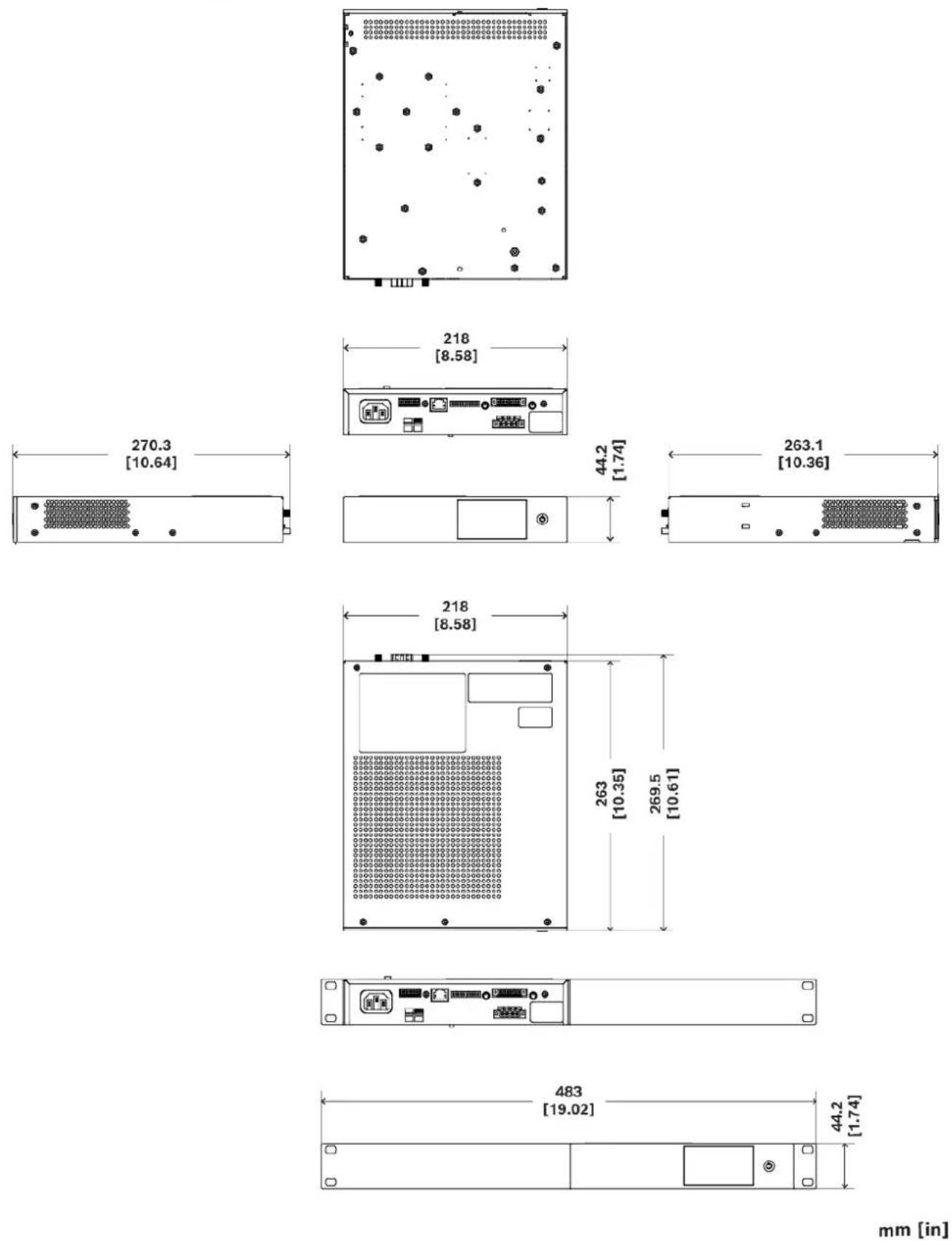
mm [in]
4.4 Mounting and ventilation

Notice!
Before mounting the device, it is recommended to make the required settings. See Indicators, controls and settings, page 25.
V600:4
19"-rack mounting
The V600:4 power amplifier has been designed for installation in a conventional 19"-equipment rack. Attach the power amp with its frontal rack mount ears using four screws and washers as shown in the illustration.
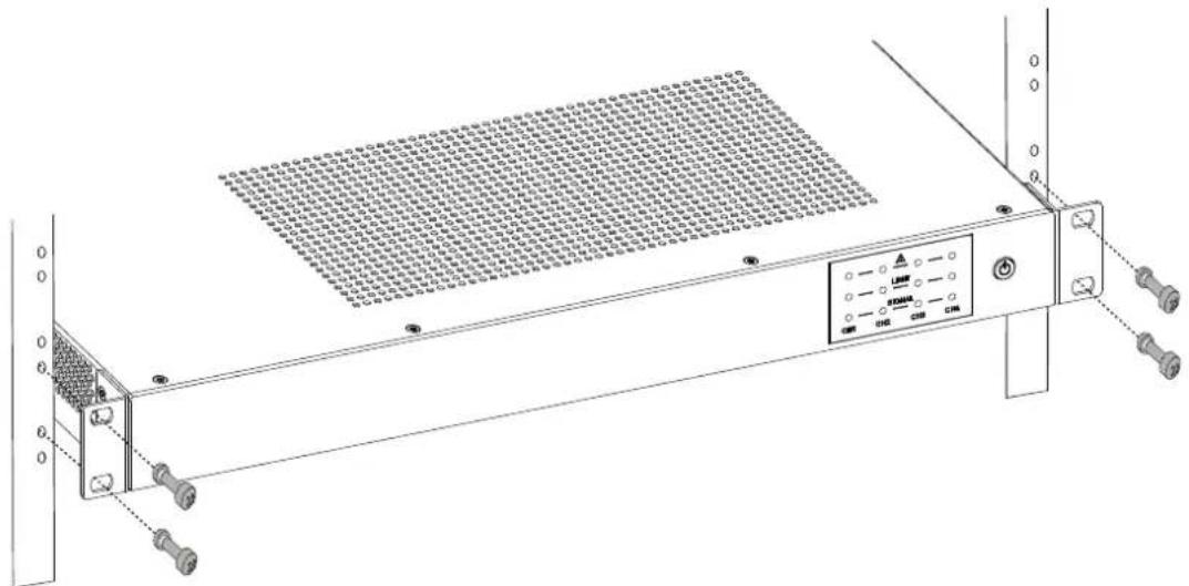
natural_image
Technical line drawing of a server rack with ventilation grilles and control panel (no text or symbols)Figure 4.1: Mounting the amplifier in a rack
Additionally securing the amplifier by rack rails might be necessary in case you intend to transport the rack. Failure to do so may result in damage to the power amplifier as well as to the rack case.
Tabletop use
If you want to use this device outside a 19"-rack on a tabletop, dismount the rack mount ears, reattach the screws back into the device and mount the four self-adhesive rubber feet on the bottom of the device.
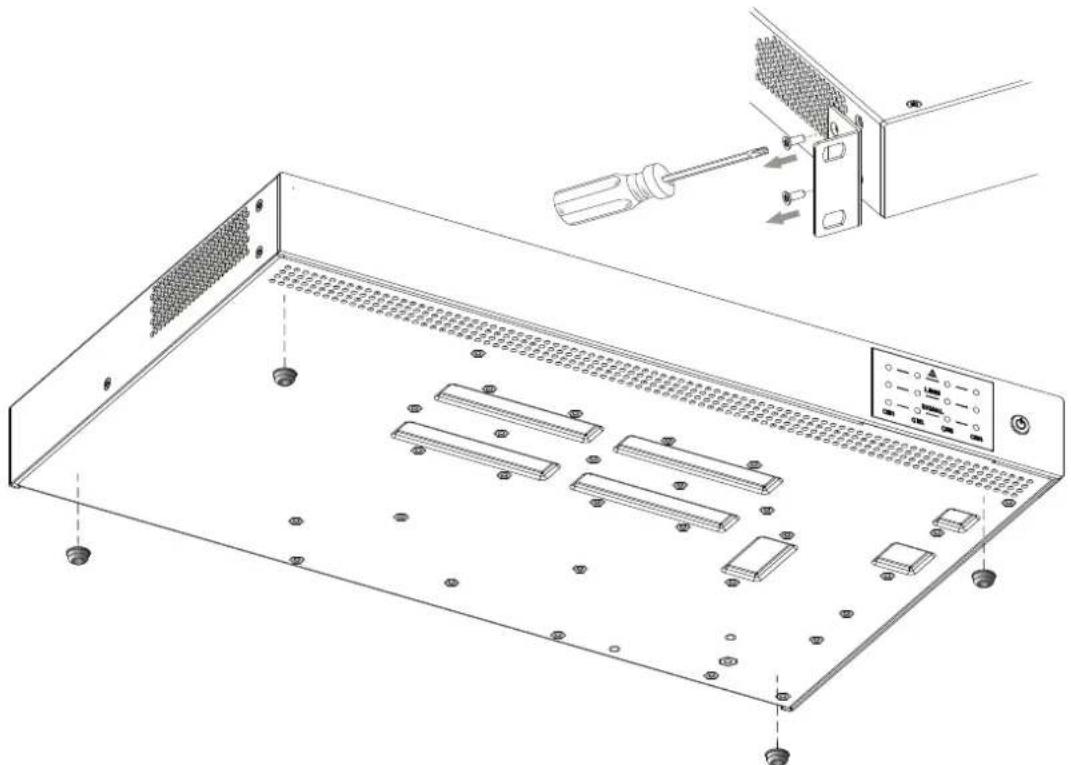
natural_image
Technical line drawing of a server rack with multiple ports and a screwdriver inserted into a rack (no text or symbols present)Figure 4.2: Dismounting the rack ears (top right) and attaching the rubber feet (bottom)
V600:2
The V600:2 amplifier has four mounting options.
Stand-alone mounting in a 19"-rack
Despite being half the size of the V600:4, the V600:2 power amplifier can be fitted alone in a standard 19"-rack.
Mount one short rack ear to the preferred side of the amplifier using the built-in screws. Unscrew the existent screws, attach the rack ear and screw them back in.
Mount the long rack ear (B) on the opposite side by unscrewing the existent screws on the side of the amplifier, attaching the long ear and screwing them back in (1).
Attach the power amp with its frontal rack mount ears (short and long) (C) using four screws and washers (2) as shown in the illustration.
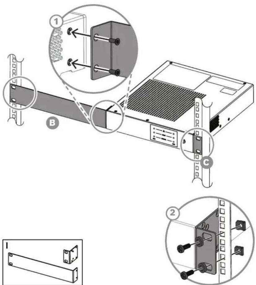
Figure 4.3: Stand-alone mounting in a 19"-rack
Side-by-side mounting in a 19"-rack
If you intend to use the full 19"-rack, you can stack two V600:2 amplifiers in one rack slot. To install both amplifiers in a side-by-side configuration:
- Mount the one short rack ear to one side of one amplifier using the existent screws (C). Unscrew the existent screws, attach the rack ear and screw them back in. Do this for both amplifiers. The two short rack ears must be in opposite sides.
- Mount the center connecting plate. Unscrew the four existent screws, attach the connecting plate and screw them back in (D) as shown in the illustration.
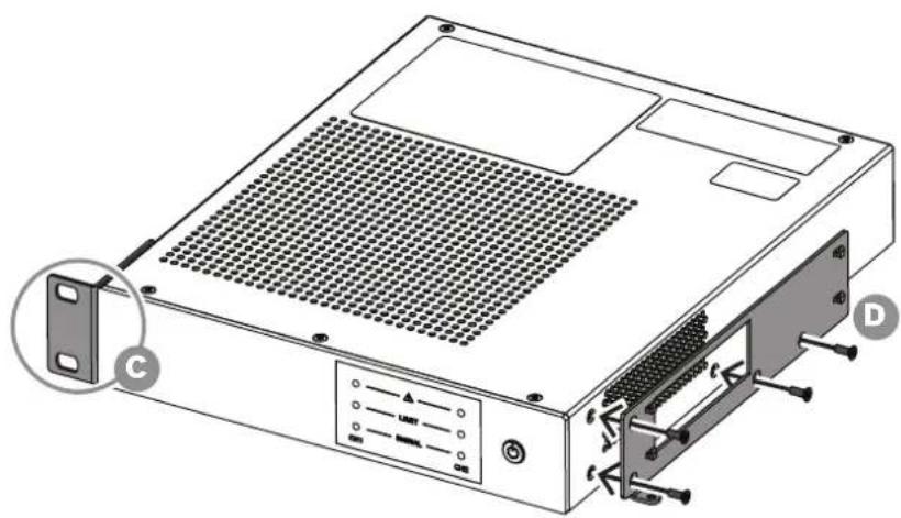
natural_image
Technical illustration of a computer drive chassis with labeled ports (no text or symbols beyond labels)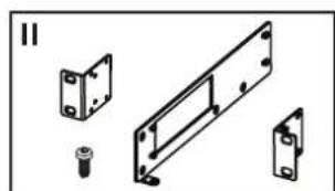
natural_image
Technical line drawing of mechanical components including a bracket, mounting base, and mounting bracket (no text or symbols)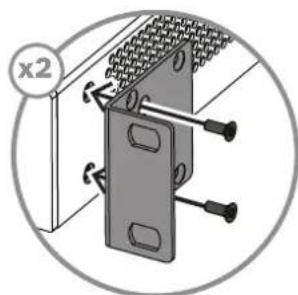
natural_image
Mechanical assembly diagram showing a bracket with bolts and a magnified view (no text or symbols)Figure 4.4: Connecting the rack ears and the connecting plate
- Once the connecting plate is attached to one amplifier, align the four holes in the side of the amplifier with the four hooks (1) and slide the other amplifier until the two amplifiers hook together (2). To prevent pushback of the amplifiers, screw in the supplied M3 bolt (3) into the screw hole on the back of the amplifier as shown in the illustration.
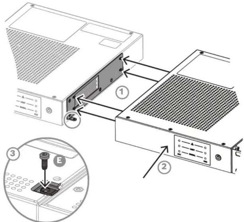
Figure 4.5: Two amplifiers hooked together with connection plate mounted and M3 bolt to prevent pushback
- Attach the power amplifier with its frontal rack mount ears using four screws and washers as shown in the illustration.
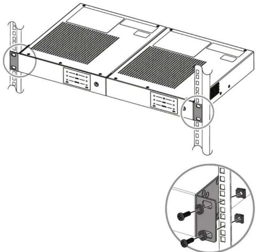
natural_image
Technical line drawing of a server rack with mounting hardware and internal components, shown in two views (no text or symbols)Figure 4.6: Side-by-side mounting in a 19"-rack
Tabletop use (over and under the table)
You can use this device outside a 19"-rack on a tabletop, mounted over or under the table. For under the table mounting:
-
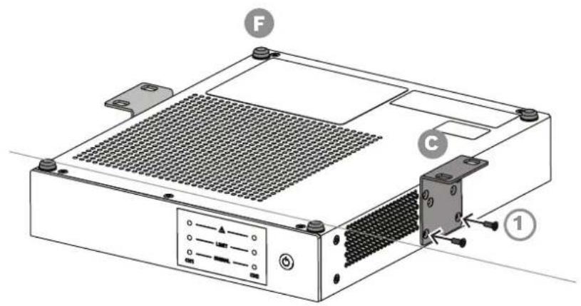
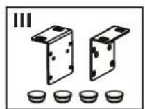
Stick the supplied rubber feet in the corners of the device top surface for more stability with this type of installation (F). Place the rubber feet in the edges of the lid so that they are not on top of the labels. For the correct position, refer to the Quick installation guide of the product.
-
Align the short rack ears with the side screws of the amplifier (C). Unscrew the existent screws, attach the rack ear and screw them back in (1).
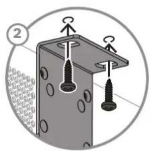
- Secure the device by screwing the rack ears to the table as shown in the illustration (2).
natural_image
Diagram of a structural joint with two screws and two hocks, enclosed in a circular frame (no text or symbols)Figure 4.7: Tabletop use - under the table
For tabletop mounting:
- Stick the supplied rubber feet in the corners of the device bottom surface for more stability with this type of installation (F).
For the correct position, refer to the Quick installation guide of the product. - Align the short rack ears with the side screws of the amplifier (C). Unscrew the existent screws, attach the rack ear and screw them back in (1).
- Secure the device by screwing the rack ears to the table as shown in the illustration (2).
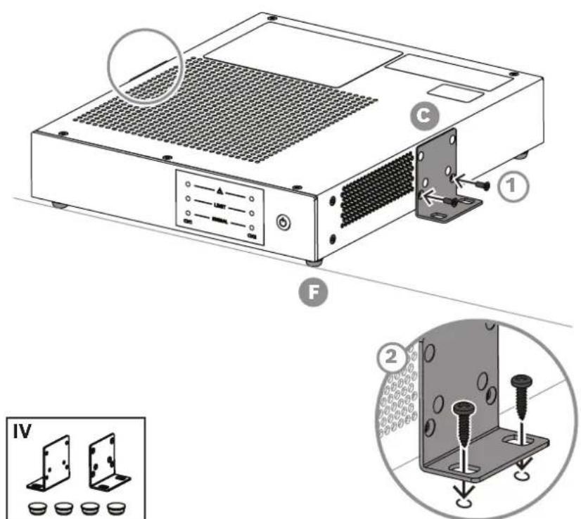
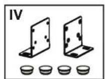
Figure 4.8: Tabletop use - over the table
Ventilation (for all models)
The airflow direction is side-to-rear. In general, setting up or mounting the power amplifier has to be done in a way that fresh air can enter unhindered at the side and exhausted air can exit at the rear. When installing the power amp in a case or rack system, attention should be paid to these details to provide sufficient ventilation.
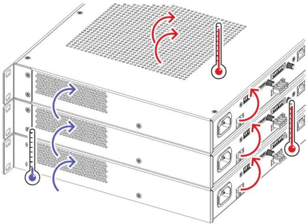
Figure 4.9: Rack mounting of several V series amplifiers. Illustration of the V600:4 model.
- Allow for an air duct of at least 60 mm between the rear panel of the power amplifier and the inner wall of the cabinet/rack case.
- Make sure that the duct reaches up to the cabinets or the rack case's top ventilation louvers.
- Leave room of at least 100 mm above the cabinet/rack case for ventilation. Since temperatures inside of the cabinet/rack case can easily rise up to 40 °C during operation of the power amp, it is mandatory to bear in mind the maximum allowable ambient temperature for all other appliances installed in the same cabinet/rack case.

Caution!
Blocking/closing the power amp's ventilation louvers is not permissible. Without sufficient cooling/ventilation, the power amplifier may enter protect mode.
Keep ventilation louvers free from dust to ensure unhindered airflow.

Notice!
Do not use the power amplifier in direct sunlight or near heat sources, like heater blowers, stoves, or any other heat radiating devices.
For fixed amplifier installations in a device control room that incorporate a central air-cooling system or air conditioners, calculating the maximum heat emission may be necessary. See also Mains operation and resulting temperature, page 23.
4.5 Fan cooling
The device is designed for desktop operation without the need to run the fan, using convection cooling. This ensures silent running in most conditions.
The temperature of the power amp's channels are supervised and monitored, as well as the power supply and control unit section. These parameters determine the fan activation to prevent output limiting from occurring.
The fan has two optimized performance levels for low and high and use the same criteria to determine the appropriate level of force cooling required.
The rotation of the fan is supervised. In case of a lock condition where the fan is not rotating, this is indicated with flashing warning LEDs on the front panel and the Fault relay. However, even in such a condition the amplifier will operate without switch-off or reduction if supervised and monitored levels are within the range of silent running parameters.
4.6 Mains operation and resulting temperature
The power drawn from the mains network is converted into output power to feed the connected loudspeaker systems and into heat. The difference between power consumption and dispensed power is called power dissipation ( P_d ). The amount of heat resulting from power dissipation might remain inside of a rack-shelf and needs to be diverted using appropriate measures.
Mains operation and resulting temperature tables allow the determination of power supply and cabling requirements. The tables are meant as auxiliary means for calculating temperatures inside of a rack-shelf system/cabinet and the ventilation efforts necessary.
The column P_d lists the leakage power in relation to different operational states. The column BTU/hr lists the dispensed heat amount per hour.
Mains voltage = 120 V
| V600:4 U | mains[V] | Imains[A] | P mains[W] | P out[W] | P_d [W](3) | BTU/hr(2) |
| Standby 120 0.07 <1.0 0 0.60 <3.4 | ||||||
| ecoRAIL mode (incl. Idle) 120 0.25 <20.0 0 19 <68 | ||||||
| 1/8 Max. Output Power Pink noise(1) | 120 2.1 | 128 4 x 19 52 | 178 | |||
| 1/3 Max. Output Power Pink noise(1) | 120 4.1 | 298 4 x 50 98 | 335 | |||
| 1/8 Max. Output Power 1 kHz 120 2.3 | 118 4 x 19 | 42 144 | ||||
| 1/3 Max. Output Power 1 kHz 120 3.8 | 283 4 x 50 | 83 283 | ||||
| V600:2 U | mains[V] | Imains[A] | P mains[W] | P out[W] | P_d [W](3) | BTU/hr(2) |
| Standby 120 0.07 <1.0 0 0.53 <3.4 | ||||||
| ecoRAIL mode (incl. Idle) 120 0.16 <12.0 0 11 <41 | ||||||
| 1/8 Max. Output Power Pink noise(1) | 120 1.9 | 112 2 x 38 36 | 123 | |||
| 1/3 Max. Output Power Pink noise(1) | 120 3.3 | 265 | 2 x 100 65 222 | |||
| 1/8 Max. Output Power 1 kHz 120 1.0 | 106 2 x 38 | 30 103 | ||||
| 1/3 Max. Output Power 1 kHz 120 3.3 | 265 | 2 x 100 65 222 |
Mains voltage = 230 V
| V600:4 U | mains[V] (4) | Imains[A] | P mains[W] | P out[W] | P_d [W] (3) | BTU/hr(2) |
| Standby 230 0.12 <1.0 0 0.97 <3.4 | ||||||
| ecoRAIL mode (incl. Idle) 230 0.23 <20.0 0 19 <68 | ||||||
| 1/8 Max. Output Power Pink noise(1) | 230 1.2 | 125 4 x 19 49 | 167 | |||
| 1/3 Max. Output Power Pink noise(1) | 230 1.7 | 280 4 x 50 80 | 273 | |||
| 1/8 Max. Output Power 1 kHz 230 0.9 | 115 4 x 19 | 39 | 133 | |||
| 1/3 Max. Output Power 1 kHz 230 2.0 | 265 4 x 50 | 65 | 222 | |||
| V600:2 U | _mains [V] (4) | I_mains [A] | P_mains [W] | P_out [W] | P_d [W] (3) | BTU/hr(2) |
| Standby 230 0.12 <1.0 0 0.77 <3.4 | ||||||
| ecoRAIL mode (incl. Idle) 230 0.16 <12 0 11 <41 | ||||||
| 1/8 Max. Output Power Pink noise(1) | 230 0.7 | 112 2 x 38 36 | 123 | |||
| 1/3 Max. Output Power Pink noise(1) | 230 1.5 | 265 | 2 x 100 65 222 | |||
| 1/8 Max. Output Power 1 kHz 230 0.7 | 112 2 x 38 | 36 | 123 | |||
| 1/3 Max. Output Power 1 kHz 230 1.6 | 267 | 2 x 100 67 2 | 28 |
- (1) Pink Noise according IEC 60268-1
- (2) 1 BTU = 1055.06 J = 1055.06 Ws
- (3) P_d = Power dissipation
- (4) The following factors can be used for easy conversion of mains current:
- 100 V = 2.3
- 240 V = 0.96
- Nominal operating condition according to IEC 62368-1 (1/8 rated output power modulated with 1 kHz)
5 Installation
- Indicators, controls and settings, page 25
- Connections, page 31
5.1 Indicators, controls and settings
Front view
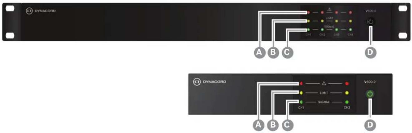
| LED Indicator description Color | |||
A Device/ | Channel fault (CH1-4) Red | ||
| B LIMIT Over driven channel (CH1-4) Yellow | |||
| C SIGNAL Input signal present (CH1-4) Green | |||
D Powe  | Diff amplifier Green is ON | Blue is ecoRAIL active, or Auto Power Down (APD) active | |
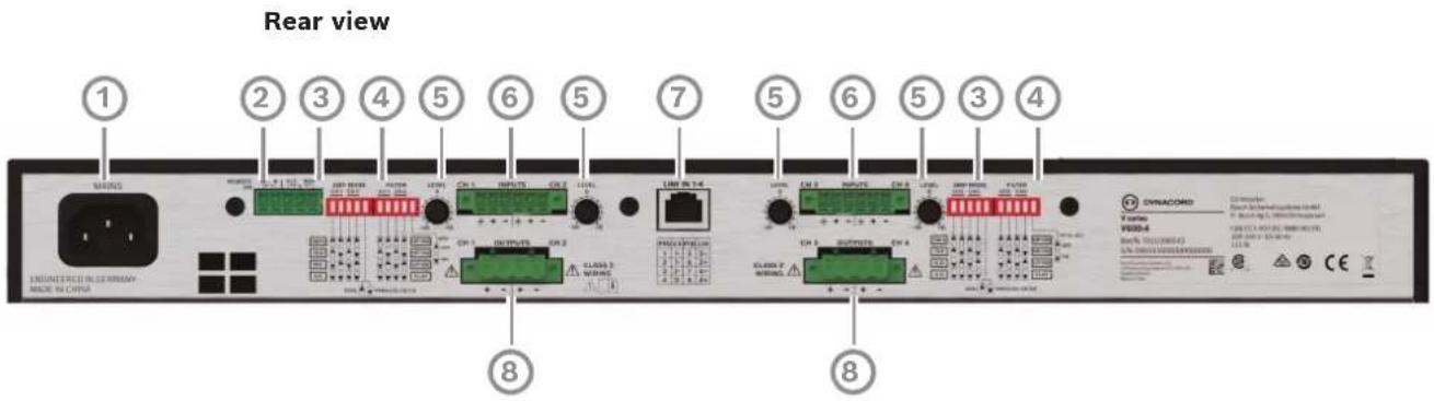
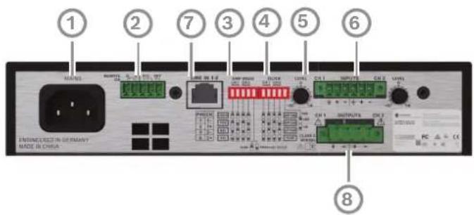
| Description | |
| 1 AC | mains input socket |
| 2 Fault relay (FLT RDY) contacts and REMOTE ON control input socket | |
| 3 AMP | MODE (CH1/CH2, CH3/CH4) and DUAL-PARALLEL DIP-switches |
| 4 FILTER (CH1/CH2, CH3/CH4), APD switches (IN1 to ALL DIP-switches in V600:4) | |
| 5 LEVEL control (CH1-4) | |
| 6 Line | level audio inputs socket (CH1/CH2, CH3/CH4) |
| 7 Line | input / through RJ45 socket (parallel to Euroblock input sockets) |
| 8 Loudspeaker OUTPUTS socket (CH1/CH2, CH3/CH4) | |
5.1.1 Set the output mode (AMP MODE)
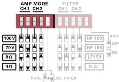
flowchart
graph TD
    A["AMP MODE"] --> B["100V"]
    A --> C["70V"]
    A --> D["8Ω"]
    A --> E["4Ω"]
    F["FILTER"] --> G["HP 100"]
    F --> H["HP 150"]
    F --> I["LP150"]
    F --> J["FLAT"]
    G --> K["APD OFF ON"]
    H --> K
    I --> K
    J --> K
    K --> L["DUAL"]
    L --> M["ALLEL CH1/2"]
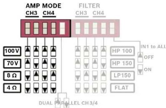
Figure 5.1: Output mode configuration (channel 3 and 4 for V600:4 only)
100 Volt and 70 Volt direct drive modes
The use of either the 70 V or 100 V modes allow connection of high impedance (HZ) loudspeaker lines without using output transformers (direct drive). In this case the maximum number of loudspeakers connected to an output channel is only limited by the amplifier channel output power.
It is recommended that this mode should be used if the distance between amplifier and speaker is larger than 50 m of cable distance (approx. 150 ft) and/or a high number of speakers with transformers are used.
When 100 V or 70 V is selected a 50 Hz High Pass filter is automatically activated to reduce the possibility of loudspeaker transformer saturation to ensure the best performance.
8 Ω mode
In 8 Ω mode the power amplifier reaches rated output power having a load of 8 Ω connected.
4 Ω mode
In 4 Ω mode the power amplifier reaches the rated output having a load of 4 Ω connected (e.g. one 4 Ω speaker or two 8 Ω speakers in parallel). These configurations can be driven by each amplifier channel. This mode usually used if multiple speakers with medium or low-power rating are driven in low impedance mode (LZ).
Refer to
- Indicators, controls and settings, page 25
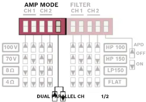
5.1.2 Set the input routing (DUAL / PARALLEL / IN1 to ALL)
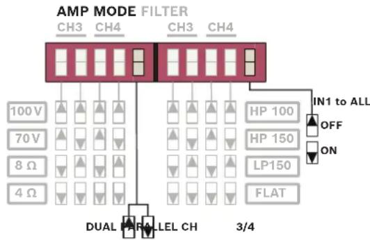
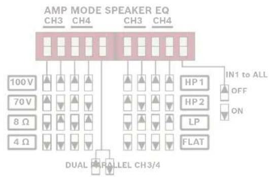
DUAL and PARALLEL modes are selected for channels 1-2 and separately for channels 3-4, using the DIP switch in the Up position for "DUAL" mode or the Down position for "PARALLEL" mode. IN1 to ALL affects all channels. If IN1 to ALL is active, it overrides the setting of DUAL/PARALLEL switch.
flowchart
graph TD
    A["AMP MODE"] --> B["100V"]
    A --> C["70V"]
    A --> D["8Ω"]
    A --> E["4Ω"]
    F["FILTER"] --> G["HP 100"]
    F --> H["HP 150"]
    F --> I["LP150"]
    F --> J["FLAT"]
    K["DUAL PARALLEL CH"] --> L["1/2"]
    M["APD OFF ON"] --> N["HLAT"]
    style A fill:#f9f,stroke:#333
    style F fill:#ccf,stroke:#333
flowchart
graph TD
    A["100V"] --> B["CH3"]
    C["70V"] --> D["CH4"]
    E["8Ω"] --> F["CH3"]
    G["4Ω"] --> H["CH4"]
    I["DUAL"] --> J["LEL CH"]
    K["HP 100"] --> L["CH3"]
    M["HP 150"] --> N["CH4"]
    O["LP150"] --> P["CH3"]
    Q["FLAT"] --> R["CH4"]
    S["IN1 to ALL"] --> T["OFF"]
    U["ON"] --> V["ON"]
    W["3/4"] --> X["3/4"]
Figure 5.2: Input routing configuration (channel 3 and 4 for V600:4 only)
DUAL mode
In DUAL mode, the two adjacent channels controlled via the DIP-switch are completely independent from each other. Using the input level controls on the power amp's rear panel allows independently adjusting the channels' amplification.
PARALLEL mode
In PARALLEL mode, the inputs of the channels CH1-2 and/or CH3-4 are directly linked. The audio signal has to be applied to the input connectors of either CH1 resp. CH3. Input level control for CH1 controls CH1 and CH2 at the same time. Respectively level control CH3 affects CH3 and CH4..
IN1 to ALL (V600:4 only)
IN1 to ALL allows the use of input 1 to be sent to all amplifier channels. IN1 to ALL is configured as either ON or OFF using the IN1 to ALL DIP switch at the rear of the device. Level control CH1 affects the volume of all output channels at the same time.
Refer to
- Indicators, controls and settings, page 25
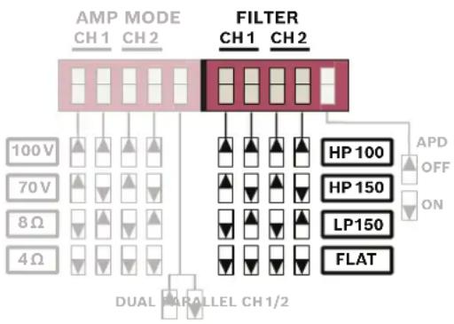
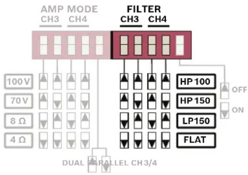
5.1.3 Set the loudspeaker parameters (FILTER)
The amplifier's FILTER settings enable the output audio to be optimized to suit particular types of speakers (e.g. subwoofers) or particular environments, allowing some optimization for voice/speech by reducing the low frequency feedback.
flowchart
graph TD
    A["AMP CH3 MODE CH4"] --> B["FILTER CH3 CH4"]
    C["100V 70V 8Ω 4Ω"] --> D["DUAL PARALLEL CH3/4"]
    E["HP 100"] --> F["OFF ON"]
    G["HP 150"] --> H["ON"]
    I["LP 150"] --> J["ON"]
    K["FLAT"] --> L["ON"]
| Mode DIP switch1 | DIP switch2 | Description |
| HP100 Up Up High Pass filter | @100 Hz, 24 dB/Oct. | |
| HP150 Up Down High Pass filter | @150 Hz, 24 dB/Oct. | |
| LP150 Down Up Low Pass filter | @150 Hz, 24 dB/Oct. | |
| FLAT | Down | Down Full range operation |
- HP100
The HP100 implements a high-pass filter with a 24 dB/Oct slope at 100 Hz within the signal path. It is particularly suited for speech and voice announcements, as it effectively attenuates undesirable low-frequency signals, such as microphone handling noise.
- HP150
The HP150 implements a high-pass filter with a 24 dB/Oct slope at 150 Hz within the signal path. Designed for implementation in a 2-way system, working in conjunction with a compatible subwoofer to further diminish low-frequency content. This configuration is especially useful for applications involving paging horns and very small ceiling speakers, where minimizing low-frequency content is desirable.
- LP150
The LP150 implements a low-pass filter with a 24 dB/Oct slope at 150 Hz within the signal path. It is intended for use in conjunction with a subwoofer, utilizing the HP150 settings to drive matching speakers.
- FLAT is suitable for full-range operation. However, for 4 and 8 Ohm operation, a 30Hz high-pass filter (with a slope of 24 dB/Oct) is applied in the signal path to attenuate extremely low-frequency noise. In the case of 70V and 100V operation, this high-pass filter is set at 50Hz to avoid transformer saturation.
Refer to
- Indicators, controls and settings, page 25
5.1.4 Set the energy safe option (APD)
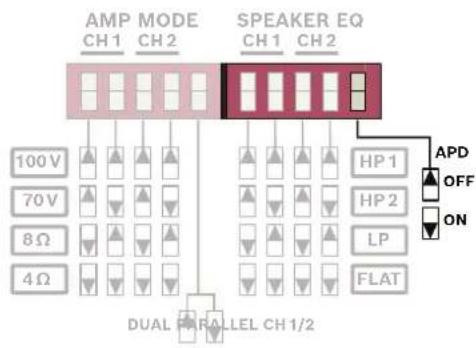
The APD (Auto Power Down) automatically places the amplifier into a low power standby mode after a period of inactivity when signal, such as a music source, is not present for an extended period.
The threshold level of the APD is -45 dBu* and will automatically activate standby if the signal is constantly below this level for 25 min across all inputs.
The amplifier is woken from APD to full activity by:
- Signal source (music) above -40 dBu threshold.
- Pressing the front panel power button.
- If configured, Remote ON wakes the amplifier from APD through a remote button.
APD is configured as either ON or OFF using the APD DIP switch at the rear of the device.
flowchart
graph TD
    A["AMP MODE CH1"] --> B["Speaker EQ CH1"]
    C["100V"] --> D["DUAL CHANNEL CH1/2"]
    E["70V"] --> D
    F["8Ω"] --> D
    G["4Ω"] --> D
    H["HP 1"] --> I["APD OFF ON FLAT"]
    J["HP 2"] --> I
    K["LP"] --> I
    L["FLAT"] --> I
flowchart
graph TD
    A["AMP MODE SPEAKER EQ"] --> B["CH3"]
    A --> C["CH4"]
    A --> D["CH3"]
    A --> E["CH4"]
    B --> F["100V"]
    C --> G["70V"]
    D --> H["8Ω"]
    E --> I["4Ω"]
    F --> J["DUAL"]
    G --> K["PARALLEL CH3/4"]
    H --> J
    I --> K
    J --> L["HP1"]
    K --> M["HP2"]
    L --> N["LP"]
    M --> O["FLAT"]
    N --> P["IN1 to ALL"]
    O --> Q["OFF"]
    O --> R["ON"]
*Activation level depends on several variables including the level controller position.
-45 dBu is an estimate based on a 0 dB position of the level control.

Notice!
For activating the device all input channels are monitored, regardless of routing switches or level setting.
Refer to
- Indicators, controls and settings, page 25
5.1.5 ecoRAIL
ecoRAIL is a dedicated low-voltage rail supply in the amplifier that significantly reduces power consumption and increases power efficiency. ecoRAIL is permanently configured, so there is no need to activate or set up this function.
5.2 Connections
- Audio inputs, page 31
- Line input RJ45, page 33
– Power outputs, page 34 - Ready/Fault relay, page 35
- Remote on, page 36
- Mains power, page 36
5.2.1 Audio inputs
Audio input connectors are either Euroblock type for 2-channels per connector, or 4-channels via the line input RJ45 connector. Both connections are in parallel, meaning they can be either used to input signal or to loop through.
Euroblock inputs
Euroblock inputs are electronically balanced. Whenever possible, using balanced audio signal feeds at the input of the power amplifier is always preferred. Unbalanced connections should only be used if the cables are very short and no interfering signals are to be expected in the vicinity of the power amplifier. In this case, bridging the screen (shielding) and the pin of the inverting input inside of the connector is mandatory. Otherwise, a 6 dB drop in level, hum and hiss noise could result. Due to their immunity against external interference sources, such as dimmers, mains connections, HF-control lines, etc., using balanced cabling and connections is always preferable.

Notice!
You must flip over the Euroblock input connector when inserting the connector to the device (screw holes of the terminal block facing downwards).
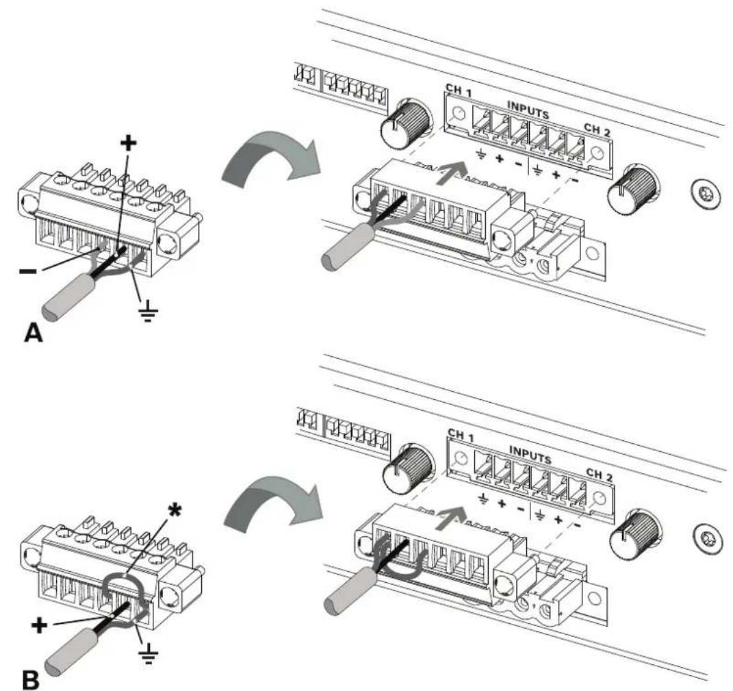
| A Balanced input connection | |
| B Unbalanced input connection | |
| + Hot | |
| - Cold | |
| 12 | Shield |
| * Jumper from cold to shield | |
- The pin out is labeled on the rear of the amplifier.
Refer to
- Indicators, controls and settings, page 25
5.2.2 Line input RJ45
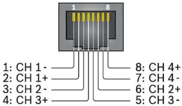
The line input RJ45 connection can be used for an input of four (V600:4) resp. two (V600:2) audio channels via a single cable, or as audio output/through when the Euroblock inputs are in use. This allows one set of inputs from the Euroblock connections to go to another amplifier. The pin out is compatible with any AES72-1E device.
- Compatible with standard CAT5e or CAT6 wiring. It is recommended to use a quality shielded STP cable for increased distances over 5 m to 25 m to reduce audio and signal degradation by maintaining balanced signal.
The wiring of AES72-1E is below.

Caution!
Do not connect the line input RJ45 with Ethernet, CAN bus, Call station, or even PoE powered ports!
Noise can occur which may damage speakers or the amplifier.
Refer to
- Indicators, controls and settings, page 25
5.2.3 Power outputs
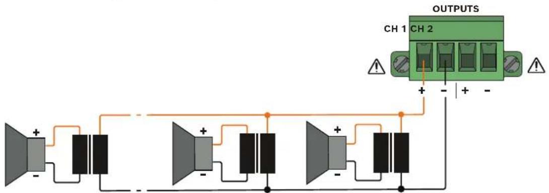
The output connectors are 2 Euroblock type for 2-channels per connector. This allows an easy pre-wiring of the cables outside the rack and a fast - one connection for multiple channels at once, without the danger of wiring errors.

Warning!
It is not allowed to interconnect terminals of different channels!

Caution!
For compliance to UL 62368-1 and CAN/CSA C22.2 No. 62368-1 all loudspeaker wiring must be Class 2 wiring (CL2); this requirement does not apply for compliance to EN/IEC 62368-1.

Caution!
Amplifier outputs may carry output voltages up to 100 V_RMS . Touching uninsulated terminals or wiring may result in an unpleasant sensation. The external wiring of these terminals requires installation by an instructed person.
LoZ 4 Ω / 8 Ω application
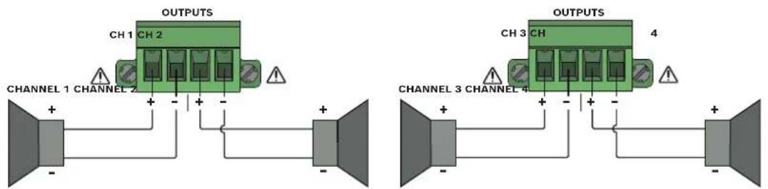
HiZ 70 V / 100 V application (Example channel 1)
Refer to
- Indicators, controls and settings, page 25
5.2.4 Ready/Fault relay
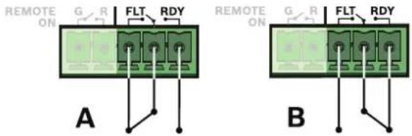
The Ready/Fault relay is a potential free relay toggle for READY or FAULT indication. This allows the amplifier to notify an external device or indicator that the amplifier status is either "RDY" (all is ok) or "FLT" (fault) and may not be functioning correctly. The next table explains the relay setting for the different operation and error modes.
| READY (RDY) / FAULT (FLT) Description | |
| RDY Amp active, all channels on | |
| FLT APD is activated or device is not on | |
| FLT One or more channels in Protect state | |
| FLT Internal error, e.g. fan blocked |
*) RDY/FLT: Indicates the closed contact.
Figure A shows the FLT (fault) condition, figure B shows the RDY (all is ok) condition.
Refer to
- Indicators, controls and settings, page 25
5.2.5 Remote on
REMOTE ON provides a simple way to remotely power-on/off the power amplifier. REMOTE ON overrides front panel power button when activated.
This can be used by an external device or a simple switch that can be located away from the amplifier for convenience.
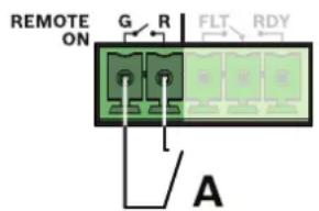
- Leaving the pins of REMOTE ON socket "open" (nothing connected) the device works with the front panel power button.
- See figure A below.
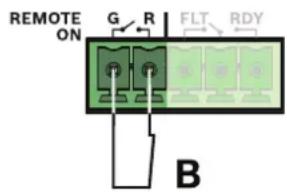
- When connecting the pins, the device is enforced to power on. This overrides the operation of the front power button.
- See figure B below.
To configure the amplifier so that users cannot turn off the device (avoiding user error), simply wire bridge the two pins together, then the front panel power button is permanently overridden.
Refer to
- Indicators, controls and settings, page 25
5.2.6 Mains power
The power amplifier receives its power supply via the MAINS IN connector. Only the provided power cord may be used. The amplifier is equipped with a wide range power supply. Relevant technical data regarding mains power consumption can be found on the product label on the rear-side of the amplifier.

Notice!
When power is restored, the device will continue in its last known mode of operation.

Caution!
During installation, always separate the power amplifier from the mains socket! Only a correctly installed and grounded wall mains outlet must be used.

Caution!
The front power button doesn't disconnect the device from mains. The only way to switch-off mains entirely is to remove the power plug.
Refer to
- Technical data, page 42
- Indicators, controls and settings, page 25
6 Operation after installation
6.1 Power on
The device can be activated by pushing the power button on the front panel. Speaker system switch-on is delayed by approximately three seconds via output relays, effectively suppressing any possible power-on noise, which otherwise might be heard through the loudspeakers.
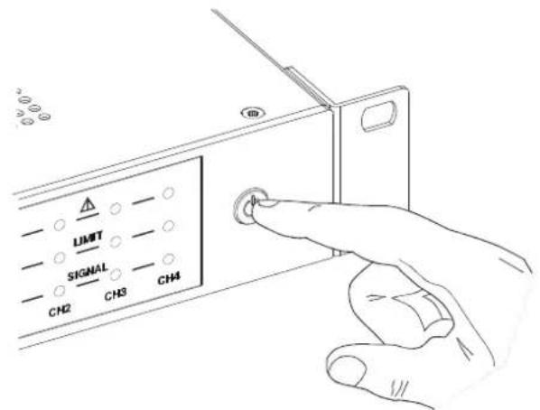
- See also Remote on, page 36.
6.2 Input level control
Adjustment of amplifier to source.
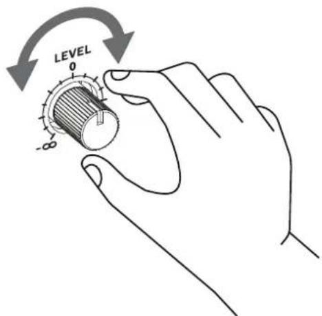
- Default is middle position. Full clockwise spends additional 6 dB to drive the amplifier even from weak sound sources.
The level control is assigned with the physical input, not the output channels. If routing PARALLEL or IN1 to ALL is used, the level control is same for all channels.

Notice!
The level control of the unused input is ineffective. If however independent level control is desired, the DUAL routing should be used instead and the inputs wired as parallel.
Refer to
- Indicators, controls and settings, page 25
7 Troubleshooting
| Problem Possible cause Solution | ||
| Amplifier does not turn on and power LED is not illuminated. | Power (plug) disconnected or the power source is giving insufficient power to the device. | Ensure power cord is securely connected to device and check the power from the mains. |
| Power button LED is continuously blinking. | Start-up fault. Contact service | agent. |
| No audio signal (no front panel LED indication). | 1) Audio input cable has come loose or has not been properly plugged in.2) Input source is not sending signal or sufficient signal.3) Input level is turned down. | 1) Check that the cables for any damage.Check that the cables are installed and wired correctly.Check that the wires are secured inside the connector, and the connector is fully plugged in and seated securely to the amplifier.2) Ensure that the input is turned up. |
| No audio is coming out of the speakers, but the input LED indication shows there is signal. | 1) Output speaker cable has come loose or has not been properly plugged in.2) Maybe there is a pilot tone present. | 1) Check that the cables for any damage.Check that the cables are installed and wired correctly.Check that the wires are secured inside the connector, and the connector is fully plugged in and seated securely to the amplifier.2) Pilot tone will usually not be audible, but the amplifier is still working correctly. |
| Audio sounds distorted. 1) Input level is too high or too low.2) Clipping of input stage.3) Music source is of poor quality.4) The amplifier is being overdriven by exceeding the max. output allowed (i.e. drained powerTANK). | 1) Ensure that the source level is not too high or too low. This could mean re-adjusting the level on the amplifier.2) Check the quality of source material.3) Turn down or consider a bigger amplifier. | |
| Audio sounds very muffled or lacks low frequencies. | Incorrect speaker settings are activated (e.g. LP used with a full range speaker). | Adjust the speaker settings on the rear of the device and ensure that the settings match they types of speakersused.See Set the loudspeaker parameters (FILTER), page 29. |
| Weak sound output, but with no fault indications. | Incorrectly wired input connectors. | Ensure that the input cables are correctly match to the polarity of the source (i.e. wired correctly).See Audio inputs, page 31. |
| Hum and hiss noise. Interference on inputs due to unbalance cables or incorrect connections. | Suggest using balanced input cable wiring.See Audio inputs, page 31. | |
| Fault LED on the amplifier channel is indicating solid red. | 1) Speaker cable has a short or the cable is damaged.2) incorrect AMP MODE selected.3) Internal amplifier channel malfunction. | 1) Check or replace speaker cables and ensure that connections are wired correctly.2) Select the appropriate AMP MODE for your speakers.See Set the output mode (AMP MODE), page 27.3) Contact service agent. |
| APD has been activated, but the amplifier is not going into standby mode. | 1) Possible unintended signal or interference on the input.2) Signal could be present on an unused channel from the desired signal routing. | Check that there are no unintended signals on any inputs (including ground loop interference). |
| Amplifier does not wake up from APD. | Input source level is too low. | Ensure that the input source is active and delivering sufficient signal to the amplifier. |
| ecoRAIL is not activating as expected. | Volume is set too high. Lower | the volume, or consider more sensitive speakers which will deliver higher volume with ecoRAIL engaged. |
| Amplifier is working, but all the red LEDs are flashing every 2 seconds and the relay is showing a fault status. | Fan error. Check blockages or | if something is caught in the fan. |
| Output power is reducing, and LIMIT LED is illuminating. | Amplifier is under extreme thermal conditions, well beyond operating specifications of 45 °C. | Consider changing the location of the amplifier and check that there is sufficient airflow around the amplifier. |
8 Maintenance
This product has been designed to operate without problems for a long period of time, with a minimum of maintenance.
In order to guarantee trouble-free operation periodically:
- Clean all units with a damp, lint-free cloth; never use water or chemicals.
– Vacuum the air vents to ensure good ventilation.
- Check all cable connections for corrosion and the screw terminals to make sure that they have not become loosened.
- Check the ground (PE) connection of the system components.
9 Technical data
V600:4
Electrical
| Output power 4 Ω 8 Ω 70 V 100 V | ||||
| Rated output power1 | 4 x 150 W | |||
| Maximum output power per channel (power sharing)1 at minimum impedance | 500 W 600 | W 500 W 600 | W | |
| Total rated output power1 | 600 W | |||
| Number of channels 4 | ||||
| Output voltage rated output power | 24.5 VRMS | 34.6 VRMS | 70.7 VRMS | 100 VRMS |
| Maximum output voltage 40.0 V | RMS | 56.0 VRMS | 70.7 VRMS | 100 VRMS |
| Rated impedance per channel 4 Ω | 8 Ω 33.3 Ω 66.7 Ω | |||
| Minimum impedance per channel | 2.6 Ω 4 Ω 10 Ω 16.7 Ω | |||
| Amplifier 4 Ω 8 Ω 70 V 100 V | ||||
| Nominal gain (+6 dBu input sensitivity, LEVEL 0 dB) | 24.0 dB | 27.0 dB | 33.2 dB | 36.2 dB |
| Maximum gain (0 dBu input sensitivity, LEVEL +6 dB) | 30.0 dB | 33.0 dB | 39.2 dB | 42.2 dB |
| THD+N(1/8 rated output power, 1 kHz) | < 0.1 % | |||
| Crosstalk(ref. 1 kHz, 12 dB below maximum) | <-70 dB | <-75 dB | <-90 dB | <-95 dB |
| Frequency response2(ref. 1 kHz, analog in to speaker out, -3 dB) | HP: 30/100/150 Hz to 20 kHzLP: 30 Hz to 150 Hz | HP: 50/100/150 Hz to 20 kHzLP: 50 Hz to 150 Hz | ||
| Damping factor(30/50 Hz to 1 kHz, ref. to rated impedance) | >80 | >160 >500 | >1000 | |
| Output stage topology | Class D, fixed frequency | |||
| Signal to noise ratio(A-weighted, ref. to rated output power, LEVEL 0 dB) | >98 dB | >100 dB | >101 dB | >103 dB |
| Output noise(A-weighted, LEVEL 0 dB) | <-68 dBu | <-67 dBu | <-62 dBu | <-61 dBu |
| Connectivity | |
| Analog audio input | |
| Type 2 x 6-pin Euroblock, 3.81 mm, male, | parallel 1x RJ45 (AES72-1E) |
| Maximum input level (LEVEL 0 dB) +18 dBu | |
| Input impedance, active balanced 20 kΩ | |
| Mains Input IEC C14 | |
| Loudspeaker output 2 x 4-pin Euroblock, 5.08 mm, | female |
| Control Port | |
| Type 1 x 5-pin Euroblock, 3.81 mm, male | |
| REMOTE ON Remote On / Standby contact | (overrides power button on front panel) |
| READY/FAULT Galvanic isolated relay, max. | 30 V_DC / 500 mA_DC |
| General | |
| Signal processing Input routing, HPF 24 dB/Oct. | selectable 100/150 Hz, LPF 24 dB/Oct. selectable 150 Hz, Flat, Peak limiter |
| Power requirements 100 V to 240 V, 50 Hz to 60 Hz AC | |
| Power consumption | |
| Consumption at 1/8 rated output power 115 W | |
| Idle mode (ecoRAIL with no input signal) < 20 W | |
| Standby mode (APD active) < 1 W | |
| Power supply topology Switching power supply with power factor correction | |
| Protections Audio limiters, high temperature, | DC, HF, short circuit, back-EMF, peak current limiters, inrush current limiters, mains over/under voltage protection |
| Front status LEDs | Signal, limit, fault LEDs per channel; power LED |
Environmental
| Climatic conditions | |
| Cooling concept Convection cooling in tabletop | application and rack application with spacing between units. Forced cooling (side to rear) in rack application without spacing between units and in extreme thermal conditions. |
| Ambient temperature limits -5 °C to +45 °C | (+23 °F to +113 °F) |
| Altitude (operating) -500 m to +5000 m | (-1614 ft to 16404 ft) |
Mechanical
| Enclosure | |
| IEC Protection class Class I (grounded) | |
| Dimensions (HxWxD)With 19" mounting brackets 44.2 x 483 x 269.5 mm | (1.74 x 19.2 x 10.6 in) |
| Weight 3.6 kg (7.9 lb) | |
1) Test signal for max. output power according IHF-A-202 (Dynamic-Headroom, burst 1 kHz / 20 ms on / 480 ms off / low level -20 dB)
^2) Selectable via Filter.
V600:2
Electrical
| Output power 4 Ω 8 Ω 70 V 100 V | ||||
| Rated output power ^1 | 2 x 300 W | |||
| Maximum output power per channel (power sharing) ^1 at minimum impedance | 500 W 600 | W 500 W 600 | W | |
| Total rated output power ^1 | 600 W | |||
| Number of channels 2 | ||||
| Output voltage rated output power | 34.6 V_RMS | 49.0 V_RMS | 70.7 V_RMS | 100 V_RMS |
| Maximum output voltage 40.0 V | _RMS | 56.0 V_RMS | 70.7 V_RMS | 100 V_RMS |
| Rated impedance per channel 4 Ω | 8 Ω 16.7 Ω 33.3 Ω | |||
| Minimum impedance per channel | 2.6 Ω 4 Ω 10 Ω 16.7 Ω | |||
| Amplifier 4 Ω 8 Ω 70 V 100 V | ||||
| Nominal gain (+6 dBu input sensitivity, LEVEL 0 dB) | 27.0 dB 30.0 dB | 33.2 dB | 36.2 dB | |
| Maximum gain (0 dBu input sensitivity, LEVEL +6 dB) | 33.0 dB 36.0 dB | 39.2 dB | 42.2 dB | |
| THD+N(1/8 rated output power, 1 kHz) | < 0.1% | |||
| Crosstalk(ref. 1 kHz, 12 dB below maximum) | <-70 dB | <-75 dB | <-90 dB | <-95 dB |
| Frequency response ^2 (ref. 1 kHz, analog in to speaker out, -3 dB) | HP: 30/100/150 Hz to 20 kHzLP: 30 Hz to 150 Hz | HP: 50/100/150 Hz to 20 kHzLP: 50 Hz to 150 Hz | ||
| Damping factor(30/50 Hz to 1 kHz, ref. to rated impedance) | >75 | >150 >250 | >500 | |
| Output stage topology | Class D, fixed frequency | |||
| Signal to noise ratio(A-weighted, ref. to rated output power, LEVEL 0 dB) | >100 dB | >102 dB | >101 dB | >103 dB |
| Output noise(A-weighted, LEVEL 0 dB) | <-68 dBu | <-67 dBu | <-62 dBu | <-61 dBu |
| Connectivity | ||||
| Analog audio input | ||||
| Connectivity | |
| Type 6-pin Euroblock, 3.81 mm, male, | parallel 1x RJ45 |
| Maximum input level (LEVEL 0 dB) +18 dBu | |
| Input impedance, active balanced 20 kΩ | |
| Mains input IEC C14 | |
| Loudspeaker output 4-pin Euroblock, 5.08 mm, female | |
| Control port | |
| Type 5-pin Euroblock, 3.81 mm, male | |
| REMOTE ON Remote On / Standby contact | (overrides power button on front panel) |
| READY/FAULT Galvanic isolated relay, max. | 30 V_DC / 500 mA_DC |
| General | |
| Signal processing Input routing, HPF 24 dB/Oct. | selectable 100/150 Hz, LPF 24 dB/Oct. selectable 150 Hz, Flat, Peak limiter |
| Power requirements 100 V to 240 V, 50 Hz to 60 Hz AC | |
| Power consumption | |
| Consumption at 1/8 rated output power 115 W | |
| Idle mode (ecoRAIL with no input signal) <12 W | |
| Standby mode (APD active) <1 W | |
| Power supply topology Switching power supply with power factor correction | |
| Protections Audio limiters, high temperature, | DC, HF, short circuit, back-EMF, peak current limiters, inrush current limiters, mains over/under voltage protection |
| Front status LEDs | Signal, limit, fault LEDs per channel; power LED |
Environmental
| Climatic conditions | |
| Cooling concept | Convection cooling in tabletop application and rack application with spacing between units. Forcedcooling (side to rear) in rack application without spacing between units and in extreme thermal conditions. |
| Ambient temperature limits -5 °C to +45 °C | (+23 °F to +113 °F) |
| Altitude (operating) -500 m to 5000 m | (-1614 ft to 16404 ft) |
Mechanical
| Enclosure | |
| IEC Protection class Class I (grounded) | |
| Dimensions (HxWxD) 44.2 x 218 x 269.5 mm | (1.74 x 8.6 x 10.6 in) |
| Weight 2.1 kg (4.6 lb) | |
^1) Test signal for max. output power according IHF-A-202 (Dynamic-Headroom, burst 1 kHz / 20 ms on / 480 ms off / low level -20 dB)
^2) Selectable via Filter.
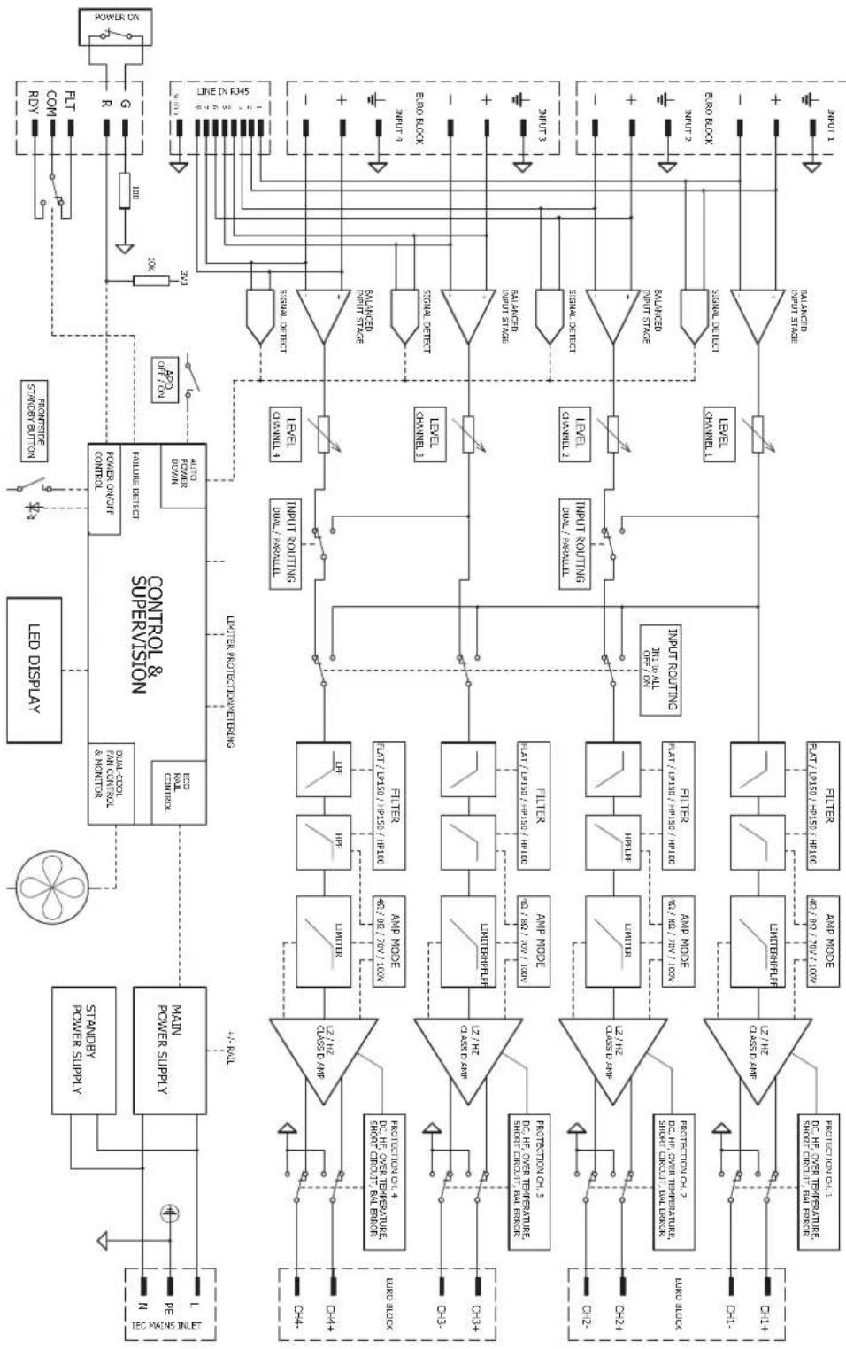
10 V600:4 Block diagram
flowchart
graph TD
    A["LED Display"] --> B["CONTROL & SUPERVISION"]
    B --> C["STANDARD POWER SUPPLY"]
    B --> D["MAX POWER SUPPLY"]
    B --> E["MODI-COUNT RAN CONTROL & MONITOR"]
    B --> F["RELTR CONTROL"]
    B --> G["RELTR POWER CONTROL"]
    B --> H["POWER ON/OFF CONTROL"]
    B --> I["POWER OFF/LOW"]
    B --> J["OUTPUT OF POWER CONTROL"]
    B --> K["OUTPUT OF OFF"]
    B --> L["POWER STRAWB SWITCH"]
    B --> M["POWER STRAWB BUTTON"]
    B --> N["POWER STRAWB INPUT"]
    B --> O["POWER STRAWB OUTPUT"]
    B --> P["POWER STRAWB CURRENT OUTPUT"]
    B --> Q["POWER STRAWB CURRENT OUTPUT"]
    B --> R["POWER STRAWB CURRENT OUTPUT"]
    B --> S["POWER STRAWB CURRENT OUTPUT"]
    B --> T["POWER STRAWB CURRENT OUTPUT"]
    B --> U["POWER STRAWB CURRENT OUTPUT"]
    B --> V["POWER STRAWB CURRENT OUTPUT"]
    B --> W["POWER STRAWB CURRENT OUTPUT"]
    B --> X["POWER STRAWB CURRENT OUTPUT"]
    B --> Y["POWER STRAWB CURRENT OUTPUT"]
    B --> Z["POWER STRAWB CURRENT OUTPUT"]
    B --> AA["POWER STRAWB CURRENT OUTPUT"]
    B --> AB["POWER STRAWB CURRENT OUTPUT"]
    B --> AC["POWER STRAWB CURRENT OUTPUT"]
    B --> AD["POWER STRAWB CURRENT OUTPUT"]
    B --> AE["POWER STRAWB CURRENT OUTPUT"]
    B --> AF["POWER STRAWB CURRENT OUTPUT"]
    B --> AG["POWER STRAWB CURRENT OUTPUT"]
    B --> AH["POWER STRAWB CURRENT OUTPUT"]
    B --> AI["POWER STRAWB CURRENT OUTPUT"]
    B --> AJ["POWER STRAWB CURRENT OUTPUT"]
    B --> AK["POWER STRAWB CURRENT OUTPUT"]
    B --> AL["POWER STRAWB CURRENT OUTPUT"]
    B --> AM["POWER STRAWB CURRENT OUTPUT"]
    B --> AN["POWER STRAWB CURRENT OUTPUT"]
    B --> AO["POWER STRAWB CURRENT OUTPUT"]
    B --> AP["POWER STRAWB CURRENT OUTPUT"]
    B --> AQ["POWER STRAWB CURRENT OUTPUT"]
    B --> AR["POWER STRAWB CURRENT OUTPUT"]
    B --> AS["POWER STRAWB CURRENT OUTPUT"]
    B --> AT["POWER STRAWB CURRENT OUTPUT"]
    B --> AU["POWER STRAWB CURRENT OUTPUT"]
    B --> AV["POWER STRAWB CURRENT OUTPUT"]
    B --> AW["POWER STRAWB CURRENT OUTPUT"]
    B --> AX["POWER STRAWB CURRENT OUTPUT"]
    B --> AY["POWER STRAWB CURRENT OUTPUT"]
    B --> AZ["POWER STRAWB CURRENT OUTPUT"]
    B --> BA["POWER STRAWB CURRENT OUTPUT"]
    B --> BB["POWER STRAWB CURRENT OUTPUT"]
    B --> BC["POWER STRAWB CURRENT OUTPUT"]
    B --> BD["POWER STRAWB CURRENT OUTPUT"]
    B --> BE["POWER STRAWB CURRENT OUTPUT"]
    B --> BF["POWER STRAWB CURRENT OUTPUT"]
    B --> BG["POWER STRAWB CURRENT OUTPUT"]
    B --> BH["POWER STRAWB CURRENT OUTPUT"]
    B --> BI["POWER STRAWB CURRENT OUTPUT"]
    B --> BJ["POWER STRAWB CURRENT OUTPUT"]
    B --> BK["POWER STRAWB CURRENT OUTPUT"]
    B --> BL["POWER STRAWB CURRENT OUTPUT"]
    B --> BM["POWER STRAWB CURRENT OUTPUT"]
    B --> BN["POWER STRAWB CURRENT OUTPUT"]
    B --> BO["POWER STRAWB CURRENT OUTPUT"]
    B --> BP["POWER STRAWB CURRENT OUTPUT"]
    B --> BQ["POWER STRAWB CURRENT OUTPUT"]
    B --> BR["POWER STRAWB CURRENT OUTPUT"]
    B --> BS["POWER STRAWB CURRENT OUTPUT"]
    B --> BT["POWER STRAWB CURRENT OUTPUT"]
    B --> BU["POWER STRAWB CURRENT OUTPUT"]
    B --> BV["POWER STRAWB CURRENT OUTPUT"]
    B --> BW["POWER STRAWB CURRENT OUTPUT"]
    B --> BX["POWER STRAWB CURRENT OUTPUT"]
    B --> BY["POWER STRAWB CURRENT OUTPUT"]
    B --> CA["POWER STRAWB CURRENT OUTPUT"]
    B --> CB["POWER STRAWB CURRENT OUTPUT"]
    B --> CC["POWER STRAWB CURRENT OUTPUT"]
    B --> CD["POWER STRAWB CURRENT OUTPUT"]
    B --> CE["POWER STRAWB CURRENT OUTPUT"]
    B --> CF["POWER STRAWB CURRENT OUTPUT"]
    B --> CG["POWER STRAWB CURRENT OUTPUT"]
    B --> CH["POWER STRAWB CURRENT OUTPUT"]
    B --> CI["POWER STRAWB CURRENT OUTPUT"]
    B --> CJ["POWER STRAWB CURRENT OUTPUT"]
    B --> CK["POWER STRAWB CURRENT OUTPUT"]
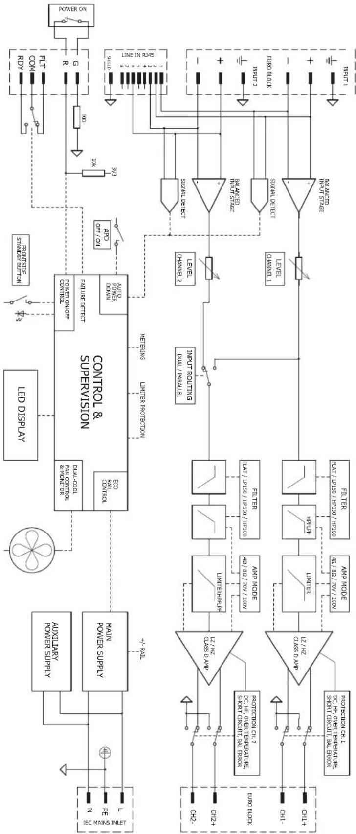
11 V600:2 Block diagram
flowchart
graph TD
    A["Input 1"] --> B["PROTECTION CH.1"]
    A --> C["PROTECTION CH.2"]
    A --> D["PROTECTION CH.3"]
    A --> E["PROTECTION CH.4"]
    A --> F["PROTECTION CH.5"]
    A --> G["PROTECTION CH.6"]
    A --> H["PROTECTION CH.7"]
    A --> I["PROTECTION CH.8"]
    A --> J["PROTECTION CH.9"]
    A --> K["PROTECTION CH.10"]
    A --> L["FILTER"]
    A --> M["HPF"]
    A --> N["Litter"]
    A --> O["UNITER"]
    A --> P["UNITER-SPRPS"]
    A --> Q["UNITER-SRPS"]
    A --> R["UNITER-SRPS"]
    A --> S["UNITER-SRPS"]
    A --> T["UNITER-SRPS"]
    A --> U["UNITER-SRPS"]
    A --> V["UNITER-SRPS"]
    A --> W["UNITER-SRPS"]
    A --> X["FILTER"]
    A --> Y["HPF"]
    A --> Z["Litter"]
    A --> AA["UNITER"]
    A --> AB["FILTER"]
    A --> AC["HPF"]
    A --> AD["Litter"]
    A --> AE["FILTER"]
    A --> AF["HPF"]
    A --> AG["Litter"]
    A --> AH["FILTER"]
    A --> AI["UNITER-SRPS"]
    A --> AJ["FILTER"]
    A --> AK["UNITER-SRPS"]
    A --> AL["FILTER"]
    A --> AM["FILTER"]
    A --> AN["FILTER"]
    A --> AO["FILTER"]
    A --> AP["FILTER"]
    A --> AQ["FILTER"]
    A --> AR["FILTER"]
    A --> AS["FILTER"]
    A --> AT["FILTER"]
    A --> AU["FILTER"]
    A --> AV["FILTER"]
    A --> AW["FILTER"]
    A --> AX["FILTER"]
    A --> AY["FILTER"]
    A --> AZ["FILTER"]
    A --> BA["FILTER"]
    A --> BB["FILTER"]
    A --> BC["FILTER"]
    A --> BD["FILTER"]
    A --> BE["FILTER"]
    A --> BF["FILTER"]
    A --> BG["FILTER"]
    A --> BH["FILTER"]
    A --> BI["FILTER"]
    A --> BJ["FILTER"]
    A --> BK["FILTER"]
    A --> BL["FILTER"]
    A --> BM["FILTER"]
    A --> BN["FILTER"]
    A --> BO["FILTER"]
    A --> BP["FILTER"]
    A --> BQ["FILTER"]
    A --> BR["FILTER"]
    A --> BS["FILTER"]
    A --> BT["FILTER"]
    A --> BU["FILTER"]
    A --> BV["FILTER"]
    A --> BW["FILTER"]
    A --> BX["FILTER"]
    A --> BY["FILTER"]
    A --> BZ["FILTER"]
    A --> CA["FILTER"]
    A --> CB["FILTER"]
    A --> CC["FILTER"]
    A --> CD["FILTER"]
    A --> CE["FILTER"]
    A --> CF["FILTER"]
    A --> CG["FILTER"]
    A --> CH["FILTER"]
    A --> CI["FILTER"]
    A --> CJ["FILTER"]
    A --> CK["FILTER"]
    A --> CL["FILTER"]
    A --> CD
    A --> CD
    B --> AD
    C --> AE
    D --> AF
    E --> AG
    F --> AH
    G --> AI
    H --> AJ
    I --> AK
    J --> AL
    K --> AM
    L --> AN
    M --> AO
    N --> AP
    P --> AQ
    Q --> AR
    R --> AS
    S --> AT
    T --> AU
    U --> AV
    V --> AW
    W --> AX
    X --> AZ
    Y --> BA
    Z --> BB
    AA --> BC
    AB --> BD
    AC --> BE
    AD --> BF
    AE --> BG
    AF --> BH
    AG --> BI
    AH --> BJ
    AI --> BK
    AJ --> BL
    AK --> BM
    AL --> BN
    AM --> BO
    AN --> BP
    AO --> OR
    AP --> AS
    AQ --> AT
    AR --> AU
    AS --> AV
    AT --> AV
    AU --> AV
    AV --> AW
    AW --> AX
    AX --> AZ
    AZ --> BA
    BA --> BB
    BB --> BC
    BC --> AD
    AD --> AE
    AE --> AF
    AF --> AG
    AG --> AH
    AH --> AI
    AI --> AJ
    AJ --> AK
    AK --> AL
    AL --> AM
    AM --> AN
    AN --> AO
    AO --> AP
    AP --> AS
    AS --> AZ
    AZ --> BA
12 Support and academy

Support
Access our support services at www.boschsecurity.com/xc/en/support/.
Bosch Security and Safety Systems offers support in these areas:
- Apps & Tools
- Building Information Modeling
- Warranty
- Troubleshooting
- Repair & Exchange
- Product Security

Bosch Building Technologies Academy
Visit the Bosch Building Technologies Academy website and have access to training courses, video tutorials and documents: www.boschsecurity.com/xc/en/support/training/
natural_image
Abstract geometric pattern composed of white semicircles on a gray background (no text or symbols)Bosch Security Systems B.V.
Torenallee 49
5617 BA Eindhoven
Netherlands
www.dynacord.com
© Bosch Security Systems B.V., 2024
- Important product information
- Safety Information
- Information
- Disposal instructions
- Old electrical and electronic appliances.
- Class B Notice for FCC and ICES 003
- About this manual
- Digital document
- Intended audience
- Copyright notice
- Trademarks
- Notice of liability
- Short information
- Document history
- Product introduction
- Features and functions
- General installation procedures
- Unpacking
- Parts included
- Dimensions
- Mounting and ventilation
- Notice!
- V600:4
- 19"-rack mounting
- Tabletop use
- V600:2
- Stand-alone mounting in a 19"-rack
- Side-by-side mounting in a 19"-rack
- Tabletop use (over and under the table)
- Ventilation (for all models)
- Caution!
- Fan cooling
- Mains operation and resulting temperature
- Installation
- Indicators, controls and settings
- Set the output mode (AMP MODE)
- Volt and 70 Volt direct drive modes
- Ω mode
- Ω mode
- Refer to
- Set the input routing (DUAL / PARALLEL / IN1 to ALL)
- DUAL mode
- PARALLEL mode
- IN1 to ALL (V600:4 only)
- Set the loudspeaker parameters (FILTER)
- - HP100
- - HP150
- - LP150
- Set the energy safe option (APD)
- ecoRAIL
- Connections
- Audio inputs
- Euroblock inputs
- Line input RJ45
- Power outputs
- Warning!
- Ready/Fault relay
- Remote on
- Mains power
- Operation after installation
- Power on
- Input level control
- Maintenance
- Technical data
- V600:4 Block diagram
- Support and academy
- Support
- Bosch Building Technologies Academy
Brand : DYNACORD
Model : V600:2
Category : Receiver