
AXM 12A - Uncategorized DYNACORD - Free user manual and instructions
Find the device manual for free AXM 12A DYNACORD in PDF.


| Product Type | Powered monitor speaker for multifunctional applications |
| Dimensions (Width x Height x Depth) | 414 x 339 x 484 mm |
| Net Weight | 14.9 kg |
| Shipping Weight | 18.4 kg |
| Maximum Amplifier Output (IHF-A) | 520 W |
| Low Amplifier Power (IHF-A / RMS) | 360 W / 260 W |
| Mid-High Amplifier Power (IHF-A / RMS) | 160 W / 75 W |
| Maximum SPL (1 m) | 128 dB (calculated) |
| Frequency Range (-10 dB) | 50 – 20000 Hz |
| Coverage Angle (Nominal) | 90° horizontal x 90° vertical |
| Crossover Frequency | 1.6 kHz |
| Transducer | 12-inch coaxial with 1.75-inch neodymium compression driver (DCX 12300) |
| Audio Inputs | 2x combo XLR/Jack (mic/line), 1x stereo RCA (aux) |
| Audio Outputs | 1x XLR THRU (parallel to input 1), 1x XLR MIX OUT |
| Phantom Power | +15 V, switchable per input 1/2 |
| Equalization | Low shelf ±10 dB @ 60 Hz, Mid peak ±10 dB (70-12000 Hz), High shelf ±10 dB @ 12 kHz |
| Filters | Low-cut (50-200 Hz, 12 dB/oct), Feedback notch (70-10000 Hz, -10 dB) |
| Master Delay | 0 – 100 ms |
| Presets | 6 factory presets, 5 user settings |
| Display | Blue backlit LC-display, dimmable |
| AC Power Input | 100-240 V AC, 50-60 Hz, 0.8-0.5 A |
| Cooling | Passive |
| Safety Class | I |
| Operating Temperature | 0 °C to 40 °C |
| Enclosure Material | 15 mm birch plywood with heavy duty structured lacquer |
| Grille | Powder coated steel with acoustic foam |
| Handles | 1 x bar carry handle, 2 x recessed grips |
| Pole Mount Adaptor | 35 mm (1-3/8 in) standard |
| Color | Black (RAL 9005, jet black) |
Frequently Asked Questions - AXM 12A DYNACORD
User questions about AXM 12A DYNACORD
0 question about this device. Answer the ones you know or ask your own.
Ask a new question about this device
Download the instructions for your Uncategorized in PDF format for free! Find your manual AXM 12A - DYNACORD and take your electronic device back in hand. On this page are published all the documents necessary for the use of your device. AXM 12A by DYNACORD.
USER MANUAL AXM 12A DYNACORD
natural_image
Black audio amplifier speaker with perforated grille and external control panel (no visible text or symbols)en | User manual

DYNACORD
GERMAN ENGINEERING EXCELLENCE
Table of contents
| 1 | Safety 4 | |
| 2 | Quick overview 6 | |
| 2.1 Shipping contents and warranty 6 | ||
| 3 | Product overview 7 | |
| 4 | Installation 8 | |
| 4.1 Floor monitor 8 | ||
| 4.2 Tripod 8 | ||
| 5 | Connection 9 | |
| 5.1 Mains input (MAINS IN) 9 | ||
| 5.2 Audio inputs 9 | ||
| 5.2.1 Microphone/line input 9 | ||
| 5.2.2 Aux input 10 | ||
| 5.3 Audio outputs 10 | ||
| 5.3.1 Thru output 10 | ||
| 5.3.2 Mix output 10 | ||
| 6 | Configuration | 11 |
| 6.1 Audio level | 11 | |
| 6.2 Display | 11 | |
| 6.2.1 Home screen | 11 | |
| 6.2.2 Menu | 12 | |
| 6.2.3 Functions | 14 | |
| 7 | Operation 15 | |
| 7.1 Quickstart | 15 | |
| 8 | Troubleshooting | 16 |
| 8.1 Avoid acoustical feedback | 16 | |
| 8.2 Replace a blown fuse | 16 | |
| 9 | Maintenance | 18 |
| 10 | Technical data | 19 |
| 10.1 | Block diagram | 21 |
| 10.2 | Frequency response | 22 |
| 10.3 | Directivity | 23 |
| 10.4 | Dimensions | 25 |
| 11 | Appendices | 26 |
| 11.1 | System examples | 26 |
1 Safety

CAUTION
RISK OF ELECTRIC SHOCK DO NOT OPEN

WARNING: TO REDUCE THE RISK OF FIRE OR ELECTRIC SHOCK, DO NOT EXPOSE THIS APPLIANCE TO RAIN OR MOISTURE.
AVIS: RISQUÉ DE CHOC ELECTRIQUE - NE PAS OUVRIR
CAUTION: TO REDUCE THE RISK OF ELECTRIC SHOCK, GROUNDING OF THE CENTRE PIN OF THIS PLUG MUST BE MAINTAINED.
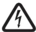
Danger!
The lightning symbol inside a triangle notifies the user of high-voltage, uninsulated lines and contacts inside the devices that could result in fatal electrocution if touched.

Warning!
An exclamation mark inside a triangle refers the user to important operating and service instructions in the documentation for the equipment.
- Read these safety notes.
- Keep these safety notes in a safe place.
- Heed all warnings.
- Observe all instructions.
- Do not operate the device in close proximity to water.
- Use only a dry cloth to clean the unit.
- Do not cover any ventilation slots. Always refer to the manufacturer's instructions when installing the device.
- Do not install the device close to heaters, ovens, or other heat sources.
- Note: The device must only be operated via the mains power supply with a safety ground connector. Do not disable the safety ground connection function of the supplied power cable. If the plug of the supplied cable does not fit your mains socket, please contact your electrician.
- Ensure that it is not possible to stand on the mains cable. Take precautions to ensure the mains cable cannot become crushed, particularly near the device connector and mains plug.
- Only use accessories/extensions for the device that have been approved by the manufacturer.
- Unplug the device if there is risk of lightning strike or in the event of long periods of inactivity. However, this does not apply if the device is to be used as part of an evacuation system!
- Have all service work and repairs performed by a trained customer service technician only. Service work must be carried out immediately following any damage such as damage to the mains cable or plug, if fluid or any object enters the device, if the device has been used in rain or become wet, or if the device has been dropped or no longer works correctly.
- Please ensure that no dripping water or spray can penetrate the inside of the device. Do not place any objects filled with fluids, such as vases or drinking vessels, on top of the device.

- To ensure the device is completely free of voltage, unplug the device from the power supply.
- When installing the device, ensure that the plug is freely accessible.
- Do not place any sources of open flame, such as lit candles, on top of the device.
- This PROTECTION CLASS I device must be connected to a MAINS socket with a safety ground connection.
Caution!
Use only manufacturer-approved carts, stands, brackets, or tables that you acquired together with the device. When using carts to move the device, make sure the transported equipment and the cart itself cannot tip over or cause injury or material damage.
IMPORTANT SERVICE INFORMATION

Caution!
This service information is for use by qualified service personnel only. To avoid the risk of electric shock, do not perform any maintenance work that is not described in the operating instructions unless you are qualified to do so. Have all service work and repairs performed by a trained customer service technician.
- Repair work on the device must comply with the safety standards specified in EN 60065 (VDE 0860).
- A mains isolating transformer must be used during any work for which the opened device is connected to and operated with mains voltage.
- The device must be free of any voltage before performing any alterations with upgrade sets, switching the mains voltage, or performing any other modifications.
- The minimum distance between voltage-carrying parts and metal parts that can be touched (such as the metal housing) or between mains poles is 3 mm, and must be observed at all times.
- The minimum distance between voltage-carrying parts and circuit parts that are not connected to the mains (secondary) is 6 mm, and must be observed at all times.
- Special components that are marked with the safety symbol in the circuit diagram (note) must only be replaced with original parts.
- Unauthorized changes to the circuitry are prohibited.
- The protective measures issued by the relevant trade organizations and applicable at the place of repair must be observed. This includes the properties and configuration of the workplace.
- Observe the guidelines with respect to handling MOS components.

Danger!
SAFETY COMPONENT (MUST BE REPLACED BY ORIGINAL PART)

Old electrical and electronic appliances
Electrical or electronic devices that are no longer serviceable must be collected separately and sent for environmentally compatible recycling (in accordance with the European Waste Electrical and Electronic Equipment Directive).
To dispose of old electrical or electronic devices, you should use the return and collection systems put in place in the country concerned.
2 Quick overview
Your AXM 12A is designed so that you can easily set it up and start using it right away. Follow the steps on the next few pages to set up your AXM 12A.

Caution!
Read all the instructions in this document and the safety notes starting on page 4 before you plug your AXM 12A into a power outlet.
2.1 Shipping contents and warranty
| Quantity Component | |
| 1 AXM 12A | |
| 1 Power cord | |
| 1 User manual | |
| 1 Important safety instructions |
Warranty
For information regarding the warranty, see www.dynacord.com
3
Product overview
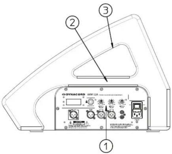
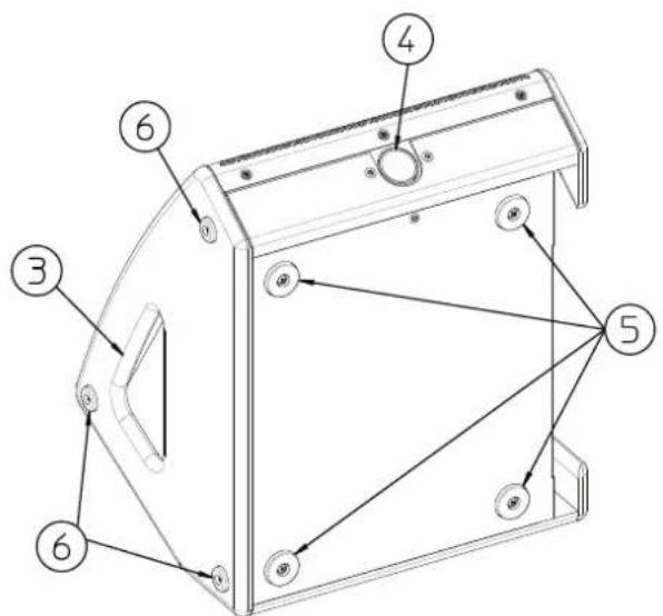
| Number | Description |
| 1 Operation and connection panel | |
| 2 Bar carry handle | |
| 3 Recessed grip | |
| 4 Pole mount adaptor | |
| 5 Bottom rubber feet | |
| 6 Protective bumper | |
4 Installation
4.1 Floor monitor
When using the DYNACORD AXM 12A as a floor monitor, make sure to:
- Place the speaker on a level, stable surface that is solid and secure.
- Route cables so that performers, production crew and audience members will not trip over the cables. Secure cables with wire ties or tape whenever possible.
4.2 Tripod
The AXM 12A loudspeaker includes a 35 mm (1-3/8 in) stand mount to allow mounting on tripod stands or above a subwoofer. Make sure to:
- Check the specifications of the speaker stand to be certain it is capable of supporting the weight of the speaker.
- Check that the speaker stand is placed on a flat, stable surface and be sure to fully extend the legs of the stand. Do not try to make the stand “taller” and compromise its structural integrity.
- Route cables and position the stand so that performers, production crew and audience members will not trip over the stand or cables and pull the speaker system over. Secure cables with wire ties or tape whenever possible.
- Do not attempt to suspend more than one speaker on a stand designed for a single speaker.
- Unless you are confident that you can safely handle lifting the weight of the speaker onto the stand, ask another person to help you place it.
5
Connection
5.1
Mains input (MAINS IN)
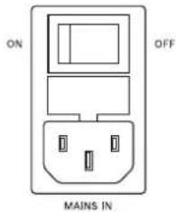
The device receives its power supply via the MAINS IN socket. Only the provided power cord may be used. Connect the device only to a mains network, which corresponds to the requirements indicated on the type plate.
The power switch allows for switching the power ON or OFF. The LCD screen lights up when the power is turned ON.
5.2
Audio inputs

Caution!
High sound level
Before making any connections or disconnections, make sure to set the corresponding level controls in the fully counterclockwise position - .
5.2.1
Microphone/line input
INPUT 1
MIC/LINE
natural_image
Simple line drawing of a circular mechanical or electrical component with two star-shaped buttons at the ends (no text or symbols)INPUT 2
MIC/LINE
natural_image
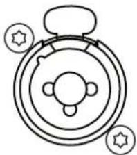
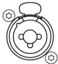
Simple line drawing of a circular mechanical or electrical component with three mounting holes and star symbols (no text or labels)Electronically balanced INPUT 1/2 MIC/LINE for the connection of a line level signal source (such as mixer etc.) or a microphone. Phantom power can be enabled (see menu item Phantom 1 or 2 in section Menu, page 12) if a condenser microphone is being used.
Establishing a connection is possible via TRS or XLR-type plugs. Whenever possible, balanced signal feed is always preferable to guard against potential noise or HF-interference.
5.2.2 Aux input
INPUT 3
AUX IN
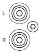
Stereo unbalanced RCA type INPUT 3 AUX IN for connecting sources such as CD players or MP3 players. See menu item MIX OUT link in section Menu, page 12 how this input can be used.
5.3 Audio outputs
5.3.1 Thru output
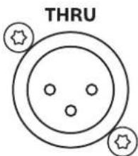
The THRU output socket is connected in parallel to INPUT 1, it is used for "carrying through" the pre-fader input signal to additional powered loudspeaker or subwoofer.
5.3.2 Mix output
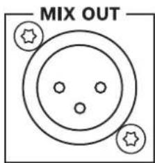
The post-fader audio signals of INPUT 1, INPUT 2 and INPUT 3 are mixed and passed to MIX OUT. The ratio of the input signals changes when the level controls INPUT 1, 2 or 3 are adjusted. This feature allows the loudspeaker to act as a basic three-channel mixer that can send the mix to another loudspeaker via the MIX OUT socket.
This output is laid out in GND-SENSING technology, a special pin assignment of the output socket, offering all advantages of the balanced signal transmission, but lets you also connect monaural plugs without a problem.
6 Configuration
6.1 Audio level
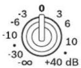
INPUT 1
MIC/LINE
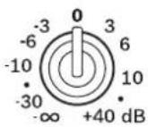
INPUT 2
MIC/LINE
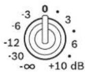
INPUT 3 AUX IN
The controls INPUT 1 and INPUT 2 allow adjusting a MIC/LINE input's sensitivity. These controls let you optimally adjust the incoming signals to the internal operation level. The INPUT 3 control is for matching the incoming line level signal of the RCA input AUX IN to the operating level of the AXM 12A.
6.2 Display
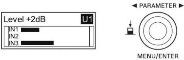
6.2.1 Home screen
The home screen appears a few seconds after switching the AXM 12A on.
Control
Turn the MENU/ENTER rotary encoder to edit the level setting or press the MENU/ENTER rotary encoder to enter the menu (see Menu, page 12).
Dimmed mode
In the menu you can set the dimmer off time of the display. After the time has elapsed without any operation of the MENU/ENTER rotary encoder, the display will enter the dimmed mode. In dimmed mode, the display brightness will be reduced to the value "Dim Bright" as set in the menu. Editing level settings by turning the MENU/ENTER rotary encoder is locked in dimmed mode, to avoid accidental volume change. Press the MENU/ENTER rotary encoder once to exit the dimmed mode.
Indications
The home screen indicates
• the current level setting (e.g. +2dB),
- the selected factory/user setting number (e.g. U1) and
- input level meters for all three audio inputs.
If the setting was edited, an "E" (Edited) is indicated next to the setting number.
Next to the current input level the level meters IN1, IN2 and IN3 indicate:
- "PK" (Peak), if the signal level of an audio input reaches 6 dB below the maximum input level, or
- "LIMIT", if the limiter of the integrated power amplifier is active.
The level meters IN1 or IN 2 indicate "P" if the corresponding input's phantom power is activated. The level meter IN3 indicates "S" (Stereo), if the menu item MIX OUT is set to R (see Menu, page 12).
6.2.2
Menu
In the menu the MENU/ENTER rotary encoder is used for navigation and for selecting and editing parameters. Turn the MENU/ENTER rotary encoder to the left or to the right to move the cursor in the menu. Press the MENU/ENTER rotary encoder to select or execute the highlighted menu item. If a menu entry was highlighted, the corresponding dialog is opened. If a parameter was highlighted, the value is shown in inverse font and can be edited by turning the MENU/ENTER rotary encoder. Press the MENU/ENTER rotary encoder again to apply the edited parameter value.
| Menu item Default Range Description | |||
| Exit - - This menu item is used to return to the home screen. | |||
| Function Monitor1 | Monitor1/2/3, GuitarCab, MAIN PA, TOP + SUB | This menu item is used to select the function the AXM 12A is used for. The type of sound the loudspeaker will deliver is adjusted accordingly. Please refer to section Functions, page 14 for details. | |
| Hi EQ 0 dB -10 - +10 dB This menu item is used to configure the high frequencies of sound. | |||
| Mid Gain 0 dB -10 - +10 dB This menu item is used to set the gain of the Mid peak filter. | |||
| Mid Freq 1000 Hz | 70-12000 Hz This menu item is used to set the center frequency of the Mid peak filter. | ||
| Lo EQ 0 dB -10 - +10 dB This menu item is used to configure the low frequencies of sound. | |||
| LoCut Off Off, 50-200 Hz This menu item is used to configure the Low-cut filter. The Low-cut filter passes high frequencies and stops low frequencies. | |||
| Feedback | Off Off, 70-10000 Hz | This menu item is used to configure the Feedback filter. The Feedback filter is a very narrow banded notch filter, which is only active in a range that is extremely susceptible for acoustical feedback. Please refer to section Avoid acoustical feedback, page 16 how to use the Feedback filter. | |
| Phantom 1 or 2 | Off | Off, On | The Phantom 1 or 2 menu is for activating phantom power (+15 V) of audio INPUT 1 or 2 whenever a suitable condenser microphone is being used. |
| MIX OUT L+R L+R, R This menu item is used to select which signal of INPUT 3 AUX IN should be output at MIX OUT and which signal should be delivered by the loudspeaker. • L+R: The left and right signals of INPUT 3 are summed. The sum is output at MIX OUT and is delivered by the loudspeaker. • R: Only the right signal of INPUT 3 is output at MIX OUT. The loudspeaker will deliver only the left signal. Please refer to section System examples, page 26 for different MIX OUT applications. | |||
| Delay | Off Off, 0.1-100.0 m | This menu item is used to delay the output signal, e.g. to compensate for differences in distance among individual loudspeakers. | |
| Dim Time 30 sec | 10-60 seconds | This menu item | is used to configure the LCD screen to dim after a certain time of inactivity. To exit dimmed mode, the encoder has to be pressed. |
| Dim Bright 50% | 0-100% This menu item is used | to set the brightness of the LCD screen in dimmed mode. | |
| Contrast 0 -10 - +10 | This menu item is used to increase or decrease the visibility of the LCD screen. | ||
| Load Settings | F1-F6, U1-U5 | Allows loading one of 6 factory or 5 user settings. | |
| Save Settings | U1-U5 | Five user memories are available to save the current settings. A name can be assigned to each user setting. | |
| Factory Reset | - | - | This menu item is used to revert the loudspeaker to the original factory default settings. All user settings will be deleted. |
| Info | - | - | This menu item provides information about the system model and the firmware version. |
| Exit | - | - | This menu item is used to return to the home screen. |
Table 6.1: LCD menu
6.2.3
Functions
This section describes the functions (factory presets) of the AXM 12A that you can select in the menu.
| Preset number | Name Description |
| F1 Monitor 1 Intended for | use as a floor monitor with a flat frequency response. |
| F2 Monitor 2 Intended for | use as a floor monitor in a very noisy environment.Certain frequencies are enhanced to help the vocals or other lead instruments to cut through the mix. |
| F3 Monitor 3 Intended for | use in a dual/twin setup. If you use two AXM 12A in front of you, acoustical coupling effects lead to a nonlinear frequency response. These coupling effects are compensated by this preset. |
| F4 GuitarCab Intended for | use as a guitar monitor. With a built in speaker simulation which emulates a 4 x 12-inch cabinet, you can connect your guitar amp/multi effects processor directly to the AXM 12A. |
| F5 MAIN PA Select this function if the AXM 12A is used as a full-range PA speaker. | |
| F6 TOP + SUB Activates a | high-pass filter when the AXM 12A is used as PA speaker together with a powered subwoofer. |
7
Operation
7.1
Quickstart

Caution!
Extremely high acoustic output
Before switching the AXM 12A's power on, make sure to set the level controls in their fully counterclockwise position - . Otherwise, this could result in extremely high acoustic output, especially when the connected audio source is already playing. It is particularly dangerous when a microphone is connected, because of the possibility of acoustic feedback.
The input section of the AXM 12A allows the connection and mixing of three individual audio signal sources:
- INPUT 1 MIC/LINE
- INPUT 2 MIC/LINE
- INPUT 3 AUX IN
Turn the MENU/ENTER rotary encoder to set the level setting indicated in the home screen to 0 dB.
MIC/LINE
- Before connecting an audio signal source, turn the INPUT 1/2 control all the way down (counterclockwise).
- Connect a microphone via XLR-type cable or a line level audio signal source (e.g. mixer, keyboard, etc.) via a 0.25-inch jack plug to a MIC/LINE input of the AXM 12A.
- Switch on the audio source or switch the microphone on and speak into the mic.
- Slowly increase the setting of the INPUT 1/2 control until the desired volume is achieved.

Caution!
Too high level setting can result in acoustic feedback. Therefore be careful when turning the INPUT 1/2 control.
- The Hi, Mid and Lo menu items let you match the sound according to acoustical conditions. Again, be sure to keep the feedback threshold in mind. Whenever you notice feedback noise after making a certain change, decrease the setting of the control that you have just used by a little bit. Alternatively, you can activate the feedback filter, please refer to sections Menu, page 12 and Avoid acoustical feedback, page 16.
AUX IN
- Before connecting an audio signal source, always turn the INPUT 3 control all the way down (counterclockwise).
- Connect an audio signal source (e.g. CD/MP-3-Player) to the AXM 12A's AUX IN using an RCA jack-type cable.
- Switch on the audio source and then slowly increase the setting of the INPUT 3 control until the desired volume is achieved.
- The Hi, Mid and Lo menu items let you match the sound according to acoustical conditions.
8 Troubleshooting
8.1 Avoid acoustical feedback
Several circumstances and conditions have an influence on how sensitive or insensitive your system is for acoustical feedback. The following notes are meant to assist you in avoiding feedback and you should take them into consideration even before you activate the feedback filter.
Best practice for avoiding feedback
- Do not position the main speaker systems behind the microphones.
- Switch off all microphones that are not in use.
- Consider the microphones' different polar patterns and characteristics, when placing the monitor speakers.
- Do not turn up the monitor system's volume higher than actually necessary.
- Try to avoid extensive equalization on channels that you want to include in your monitor mix.
- Keep in mind, that a microphone "behaves" differently when somebody stands right in front of it.
- Position the microphones as directly as possible to the sound source.
Using the feedback filter
If you still have the feeling that the monitor system's acoustic output is not sufficient, after considering the above mentioned precautions, you can use the feedback filter to mute the frequency that tends to generate feedback the most.
Therefore, you have to perform the following steps:
- Increase the INPUT 1/2 level until the limit is reached where feedback starts. The slightly "hovering" sound that you hear is generated by the system itself.
- Select the menu item Feedback, by default the feedback filter is deactivated ("Off").
- Turn the MENU/ENTER rotary encoder to activate the feedback filter and set the filter to the frequency where the "sound" disappears.
The feedback filter attenuates the level of the corresponding frequency band by about 10 dB. Since the filtered band is extremely narrow, an alteration in the sound of your monitor system is hardly audible.

Caution!
Please be extremely careful in driving the system just below the feedback limit. Careless operation, resulting in feedback noise at high SPL, can cause severe damage to your speaker systems and – even more important – the human ear.
8.2 Replace a blown fuse
First, turn off the power of the unit and pull the mains plug. Then, open the cover next to the mains socket to replace the blown fuse. Only use following fuse type: 5x20 mm, 250 V, 4 A
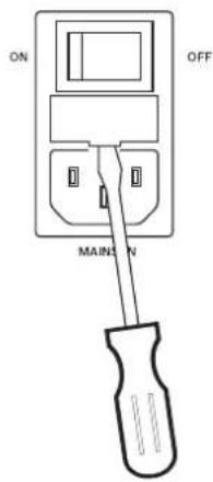
Figure 8.1: Open the fuse cover using a screw driver

Warning!
Never install a fuse larger than what the circuit was designed to be protected with.
9 Maintenance
The AXM 12A does not require any maintenance.
10
Technical data
| Description Powered monitor speaker for multifunctional applications | |
| Maximum amplifier output capability, IHF-A | 520 W |
| Low amplifier power 360 W IHF-A, 260 W RMS | |
| Mid-high amplifier power 160 W IHF-A, 75 W RMS | |
| Maximum SPL (1 meter) 128 dB (calc.) | |
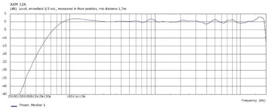
| Frequency range (-10 dB) 50-20000 Hz | |
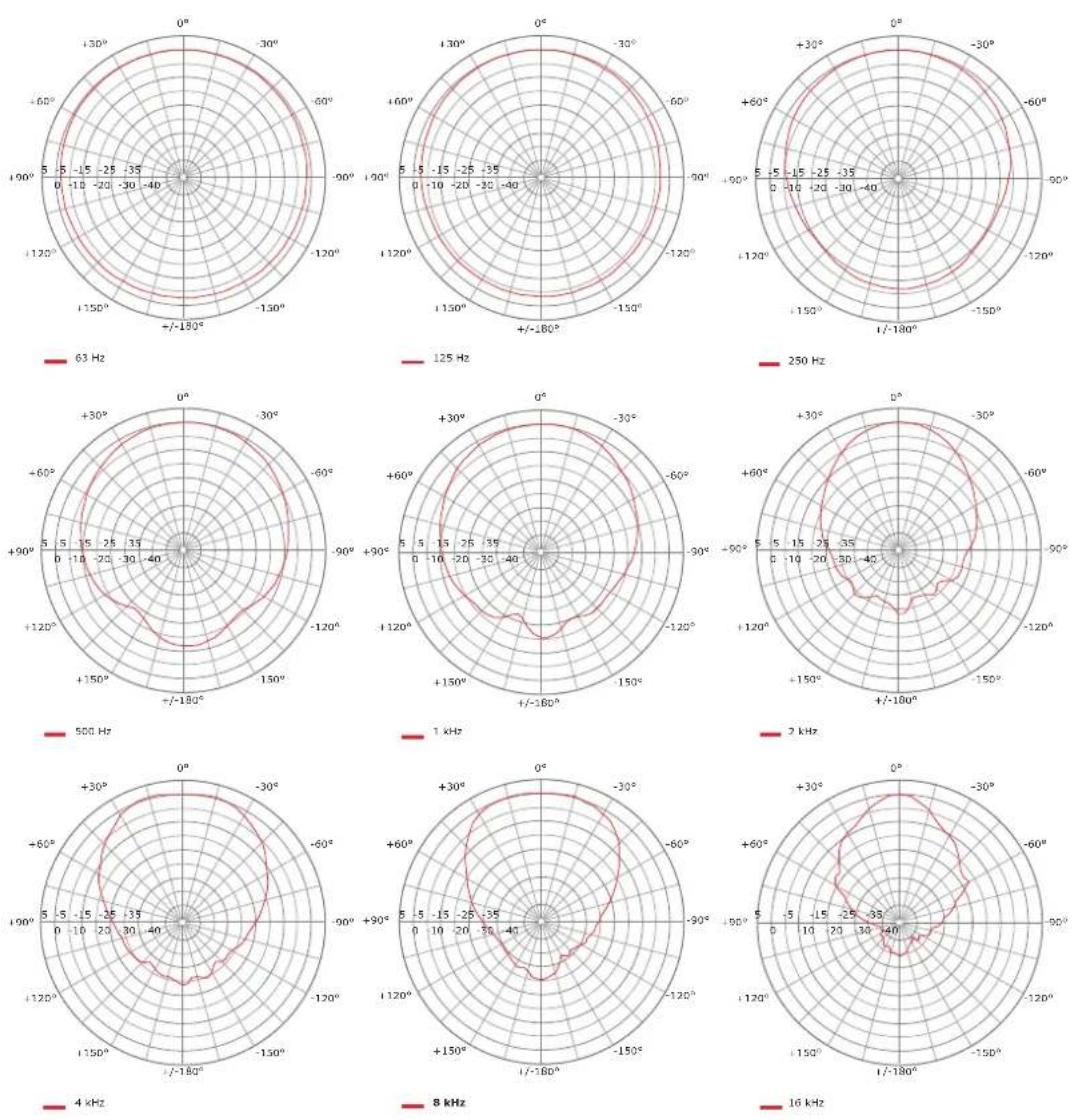
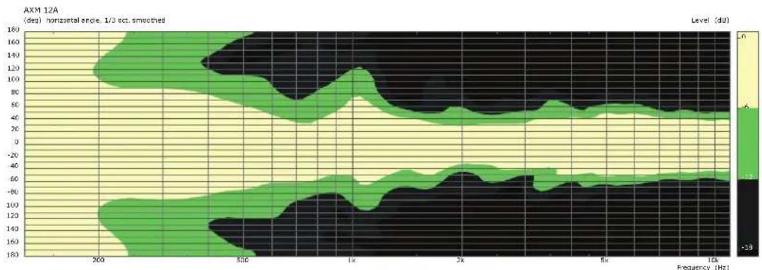
| Coverage angle nominal 90° horizontal x 90° vertical | |
| Crossover frequency 1.6 kHz | |
| Transducer DCX 12300, 12-inch/1.75-inch 2-way coaxial transducer with lightweight neodymium compression driver | |
| Audio sockets | |
| • Inputs 2 x Mono XLR/Jack socket (MIC/LINE), switchable phantom power (+15 V) 1 x Stereo RCA (AUX IN) | |
| • Outputs 1 x XLR THRU (parallel to MIC/LINE 1) 1 x XLR MIX OUT | |
| Equalization | |
| • Low shelving filter ±10 dB / 60 Hz | |
| • Mid peak filter ±10 dB / 70-12000 Hz | |
| • High shelving filter ±10 dB / 12 kHz | |
| Filter | |
| • Low-cut filter f = 50-200 Hz, 12 dB/oct. | |
| • Feedback filter 70-10000 Hz, Notch, -10 dB | |
| Master delay 0-100 m | |
| Settings | 6 factory presets, 5 user settings |
| Display | Blue backlit LC-display, dimmable |
| AC power input | 100-240 V AC, 50-60 Hz |
| AC power consumption | 0.8-0.5 A |
| Cooling | Passive |
| Safety class | I |
| Operating temperature 0 °C to 40 °C | |
| Product dimensions (Width x Height x Depth) | 414 x 339 x 484 mm |
| Net weight 14.9 kg | |
| Shipping weight 18.4 kg | |
| Enclosure material 15 mm birch plywood | |
| Enclosure finish Heavy duty structured lacquer | |
| Color Black (RAL 9005, jet black) | |
| Grille Powder coated steel, acoustic foam | |
| Pole mount adaptor 1 | |
| Handles 1 x bar carry handle, 2 x recessed grip | |
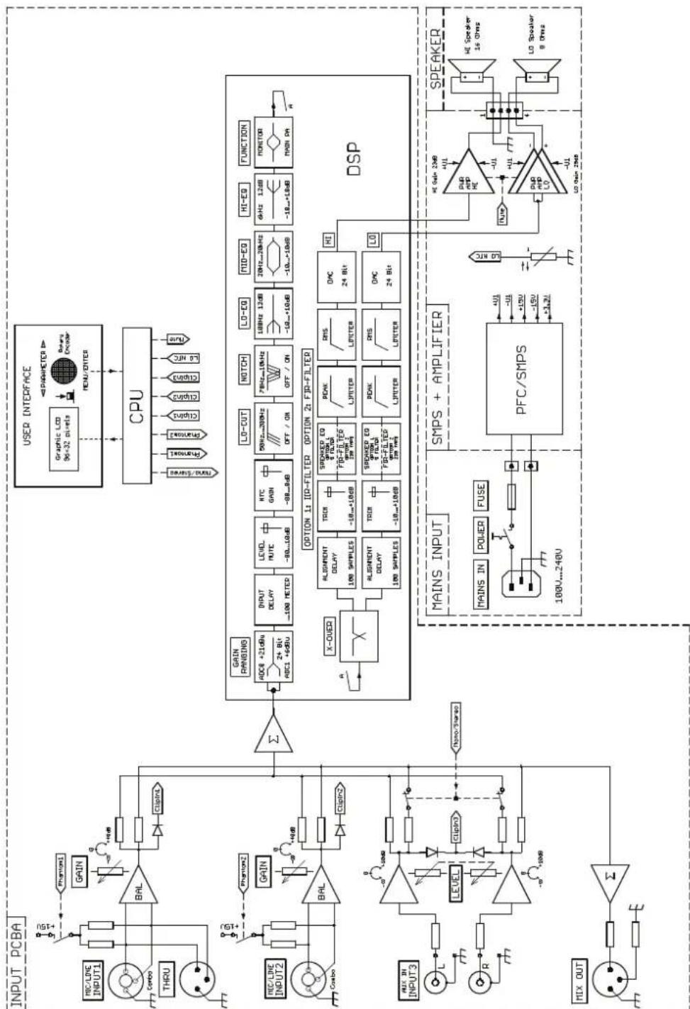
Block diagram10.1
flowchart
graph TD
    subgraph INPUT PCB
        direction TB
        A["Input PCBA"] --> B["MC/LPE INPUT1"]
        A --> C["THRU"]
        A --> D["Combo"]
        A --> E["GAIN"]
        A --> F["BAL"]
        F --> G["Circuit1"]
        G --> H["Σ"]
        H --> I["PGN2"]
        I --> J["PGN"]
        J --> K["GAIB"]
        K --> L["ACCE +21dB"]
        L --> M["INPUT DELAY -100 METER"]
        M --> N["LEVEL ROUTE -80...10dB"]
        N --> O["HTC GAIN -98...8dB"]
        O --> P["LO-CUT 50Hz-200Hz OFF / ON"]
        P --> Q["NOTCH 7MHz-10kHz OFF / ON"]
        Q --> R["LO-EQ 100Hz 12dB -10...+10dB"]
        R --> S["NHD-EQ 20Hz-20kHz -10...+10dB"]
        S --> T["HI-EQ 6kHz 12dB -18...+18dB"]
        T --> U["FUNCTION MAIN DA"]
    end

    subgraph OUTPUT
        V["Input3"] --> W["L"]
        W --> X["R"]
        X --> Y["LEVEL"]
        Y --> Z["Circuit3"]
        Z --> AA["Σ"]
        AA --> AB["GPIO/Sharp"]
    end

    subgraph DSP
        AC["X-OVER"] --> AD["ALIGNMENT DELAY 100 SAMPLES"]
        AD --> AE["TGIR -18...+10dB"]
        AE --> AF["SPEAKED EQ OPTION 1 & FILTER FBG-FILTER OPTION 2 & RMS RMS"]
        AF --> AG["PEAK LIPITER"]
        AG --> AH["RMS LIPITER"]
        AH --> AI["OPC 24 Bit"]
        AI --> AJ["HI"]
        AJ --> AK["L0"]
        AK --> AL["DSP"]
    end

    subgraph MAINS INPUT
        AM["MAINS INPUT"] --> AN["SMPS + AMPLIFIER"]
        AN --> AO["MAINS IN POWER FUSE 100V...240V"]
        AO --> AP["PFC/SMPS"]
        AP --> AQ["+U -U +15V -15V +1.2V"]
        AQ --> AR["DIJ AMP ME"]
        AR --> AS["HI Gain 23dB +UL -UL +UL"]
        AS --> AT["DND AMP LO"]
        AT --> AU["Speaker 16 GHz"]
        AU --> AV["LO Gain 24dB -UL -UL"]
        AV --> AW["L0 Speaker 8 GHz"]
    end

    subgraph SPEAKER
        AX["Speaker 16 GHz"] --> AY["HI Speaker 8 GHz"]
    end
10.2
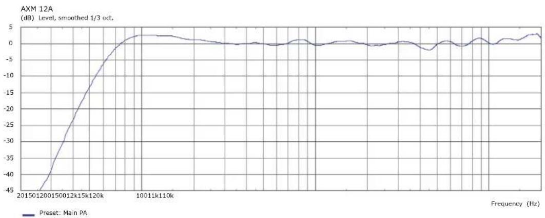
Frequency response
line
| Frequency (Hz) | Level (dB) | | -------------- | ---------- | | 20150 | -45 | | 1200 | -30 | | 1500 | -20 | | 12k | -10 | | 15k | -5 | | 120k | 0 | | 10011 | 0 | | 1k | 0 | | 110k | 0 | | 12k | 0 | | 15k | 0 | | 120k | 0 | | 15k | 0 | | 120k | 0 | | 10011 | 0 | | 1k | 0 | | 110k | 0 | | 12k | 0 | | 15k | 0 | | 120k | 0 | | 15k | 0 | | 120k (final)| 0 | | 10011 | 0 | | 1k | 0 | | 110k | 0 | | 12k | 0 | | 15k | 0 | | 120k (final)| 0 |Figure 10.1: Frequency response (preset: Main PA)
line
| Frequency (Hz) | Level (dB) | | -------------- | ---------- | | 20150 | -45 | | 1200 | -35 | | 1500 | -25 | | 12k | -15 | | 15k | -5 | | 120k | 0 | | 100k | 0 | | 11k | 0 | | 110k | 0 | | 100k | 0 | | 100k+ | 0 | | 100k+ | -5 | | 100k+ | -10 | | 100k+ | -15 | | 100k+ | -20 | | 100k+ | -25 | | 100k+ | -30 | | 100k+ | -35 | | 100k+ | -40 | | 100k+ | -45 |Figure 10.2: Frequency response (preset: Monitor 1)
10.3
Directivity
Horizontal directivity
heatmap
| Frequency (Hz) | Level (dB) | | -------------- | ---------- | | 200 | -28 | | 500 | -28 | | 1k | -28 | | 2k | -28 | | 5k | -28 | | 10k | -28 | | 150 | -28 |Figure 10.3: Horizontal directivity plot
Vertical directivity
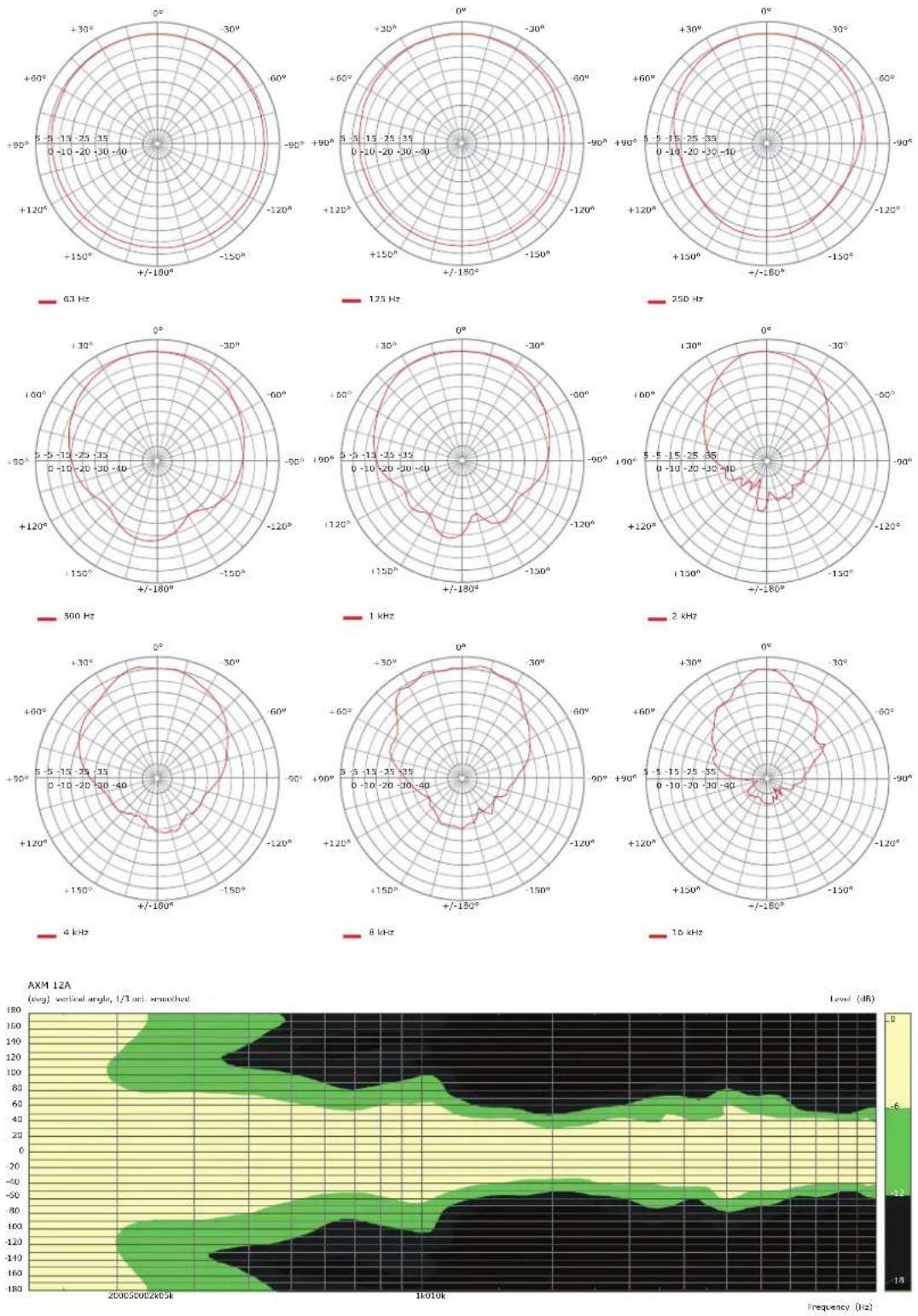
Figure 10.4: Vertical directivity plot
Dimensions10.4
![414 mm [16,3°] 409 mm [16,1°] 334 mm [13,2°] 339 mm [13,4°]](/content/2026/05/876243/images/28442c44eb831ed8ea132f13183743a96dda071713a79e5a3c9cf61ab5d36bb5.jpg)
FRONT VIEW
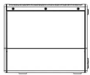
natural_image
Simple line drawing of a rectangular frame with two horizontal lines and three small dots at the top (no text or symbols)REAR VIEW
![459 mm [18.47] 33° 125 mm [4.97]](/content/2026/05/876243/images/2cb0500f9993f1173e0f91f7ee38b050f591c60432fb6122c1e907fc774367b1.jpg)
SIDE RIGHT
![484 mm [19,1°] 23° 80 mm [3,1°] 436 mm [17,2°]](/content/2026/05/876243/images/1cbd9cadf0b7916c05be128e9fcdfe0fe805203f31fc637cb0b4abbea6971343.jpg)
SIDE LEFT
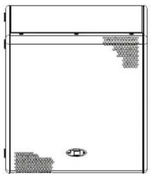
natural_image
Simple line drawing of a container with a lid, bottom, and a small inset image (no text or symbols)TOP VIEW
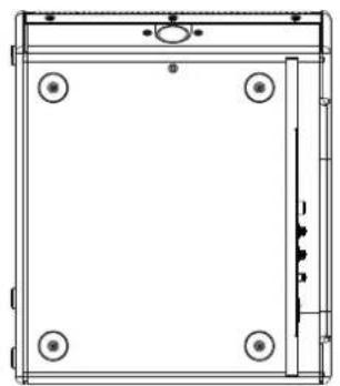
natural_image
Technical line drawing of a rectangular frame with four corner holes and mounting points (no text or symbols)BOTTOM VIEW
11
Appendices
11.1
System examples
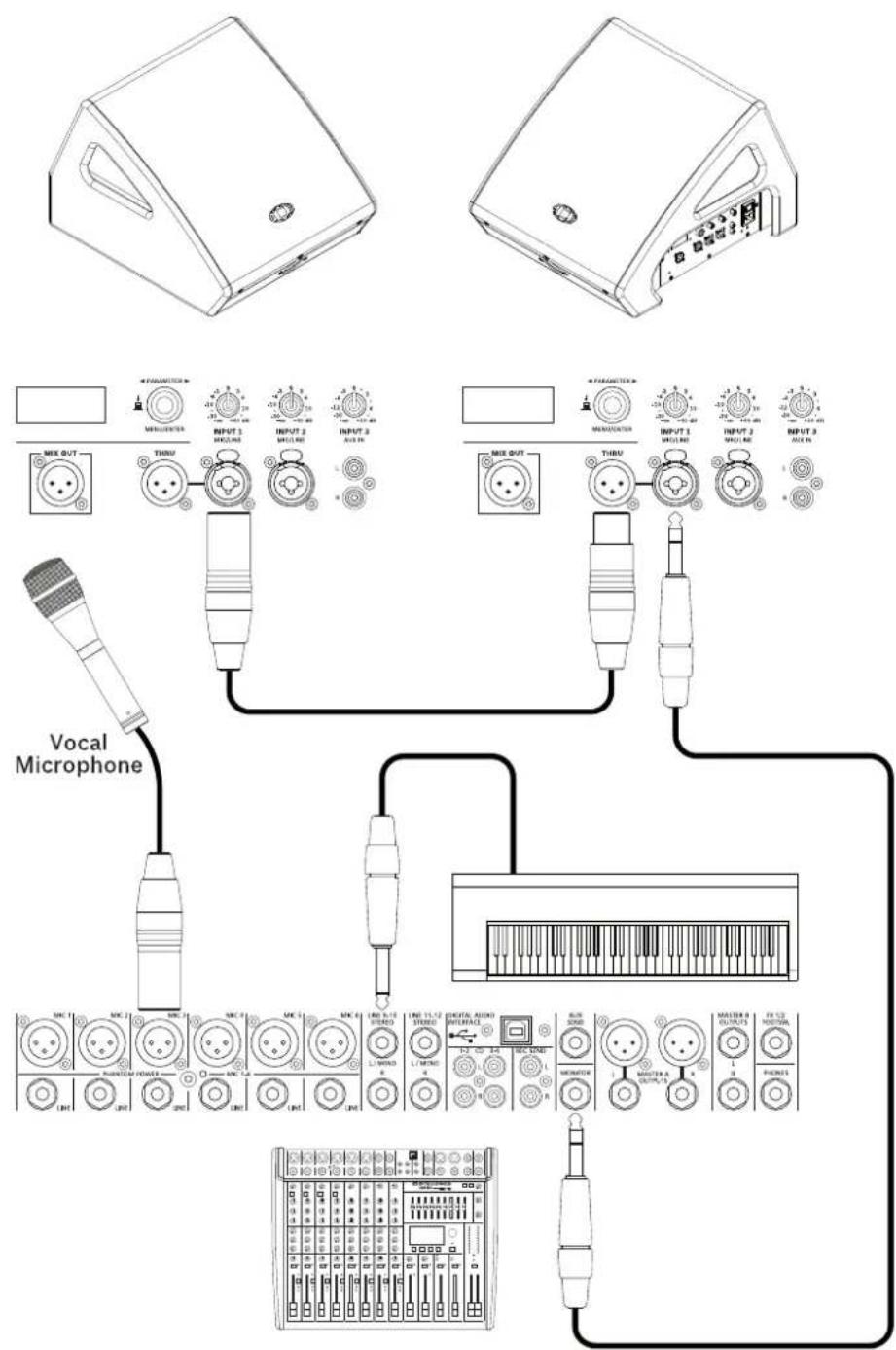
Figure 11.1: Monitor application with two AXM 12A connected to a CMS mixer
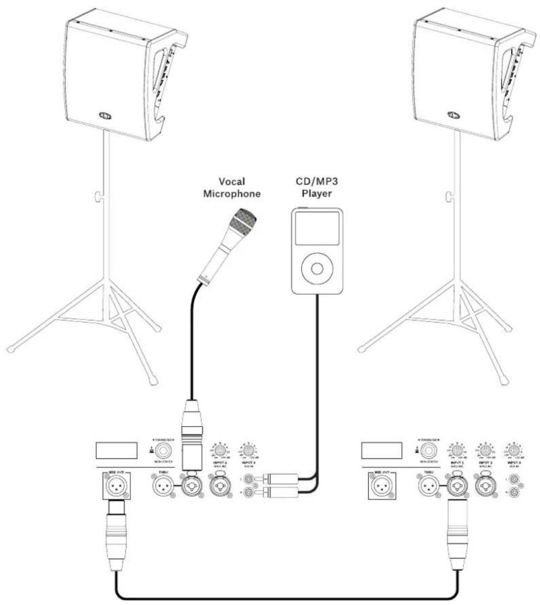
Figure 11.2: Tripod application with stereo playback plus microphone. Set the menu item MIX OUT of the left AXM 12A to R, so the left (L) signal is played only from the left AXM 12A. The right (R) signal is output via MIX OUT and is played from the right AXM 12A. The microphone signal is played by both speakers.
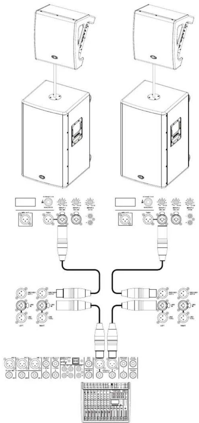
Figure 11.3: Application with two PowerSub 212 powered subwoofers. Set the menu item Function to MAIN PA, as the AXM 12As are connected to the MID/HIGH outputs of the subwoofers.
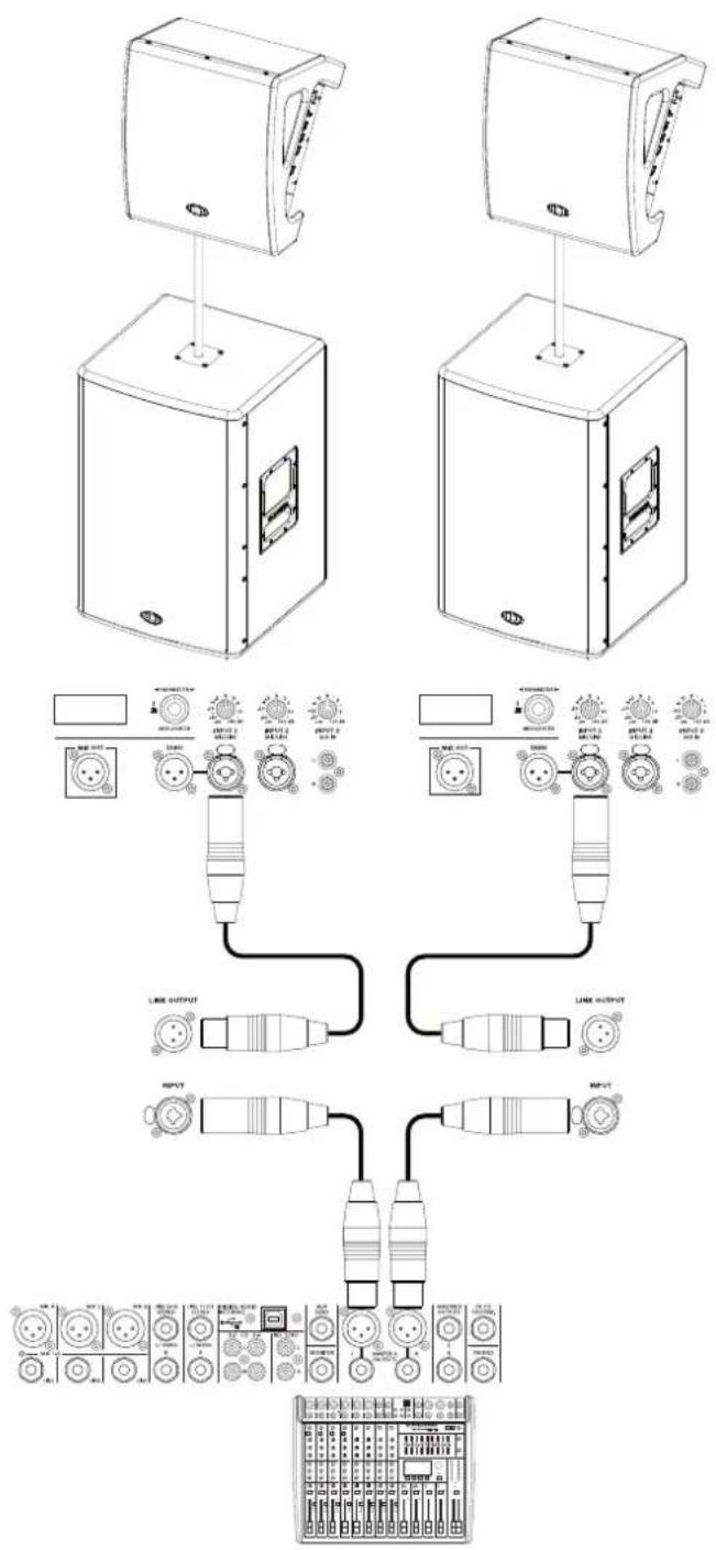
Figure 11.4: Application with two A 118A powered subwoofers. Set the menu item Function to TOP + SUB, as the AXM 12As are connected to the LINK OUTPUTs of the subwoofers.
- Safety
- CAUTION
- Danger!
- Warning!
- Caution!
- IMPORTANT SERVICE INFORMATION
- Old electrical and electronic appliances
- Quick overview
- Shipping contents and warranty
- Warranty
- 3
- Product overview
- Installation
- Floor monitor
- Tripod
- 5
- Connection
- 5.1
- Mains input (MAINS IN)
- 5.2
- Audio inputs
- 5.2.1
- Microphone/line input
- Aux input
- INPUT 3
- Audio outputs
- Thru output
- Mix output
- Configuration
- Audio level
- Display
- Home screen
- Control
- Dimmed mode
- Indications
- 6.2.2
- Menu
- 6.2.3
- Functions
- 7
- Operation
- 7.1
- Quickstart
- MIC/LINE
- AUX IN
- Troubleshooting
- Avoid acoustical feedback
- Best practice for avoiding feedback
- Using the feedback filter
- Replace a blown fuse
- Maintenance
- 10.2
- 10.3
- Directivity
- 11
- Appendices
- 11.1
- System examples
Brand : DYNACORD
Model : AXM 12A
Category : Uncategorized