
IAN 74884 - Exercise bike CRIVIT - Free user manual and instructions
Find the device manual for free IAN 74884 CRIVIT in PDF.


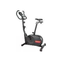
| Product Type | Exercise Bike (Ergometer) |
| Model | IAN 74884 |
| Brand | Crivit |
| Max User Weight | 150 kg (330 lbs) |
| Power Supply | 230 V ~ 50 Hz, 0.35 A |
| Resistance System | Eddy Current Brake (EMS) |
| Resistance Levels | 32 (adjustable via computer) |
| Maximum Power | 400 Watts |
| Flywheel Weight | Approx. 9.2 kg |
| Display | Color LCD with backlight |
| Training Programs | Quick Start, Manual, Hill, Interval, Individual, Watt, Target Heart Rate, Test, BMR/BMI/Fat Measurement, Cool-down |
| Heart Rate Monitoring | Capacitive hand pulse sensors and 5 kHz chest strap receiver (strap not included) |
| Seat Adjustment | Horizontal, vertical (multiple positions), and tilt adjustment |
| Handlebar | Multi-position with soft grip cover and tilt adjustment |
| Pedals | Self-righting with safety straps (left/right marked) |
| Bottle Holder | Included (bottle included) |
| Transport | Front transport rollers |
| Floor Levelling | Rear knurled screws |
| Safety Features | Freewheeling, emergency stop via computer pause, CE certified |
| Maintenance | Clean with damp cloth; avoid harsh cleaners; check screw connections regularly |
| Warranty | 3 years from date of purchase |
| Dimensions (approx.) | Not specified |
| Weight (approx.) | Not specified |
Frequently Asked Questions - IAN 74884 CRIVIT
User questions about IAN 74884 CRIVIT
0 question about this device. Answer the ones you know or ask your own.
Ask a new question about this device
Download the instructions for your Exercise bike in PDF format for free! Find your manual IAN 74884 - CRIVIT and take your electronic device back in hand. On this page are published all the documents necessary for the use of your device. IAN 74884 by CRIVIT.
USER MANUAL IAN 74884 CRIVIT
natural_image
Exterior view of a white and black exercise bike with visible sensor and front-mounted device (no text or symbols on the bike itself)ErgomEtEr
cycle Ergometer Instructions by use

30 from every job in the district paper and get a place of the customer's work
CE
D7/ST Akkassay-roti Sclerlektanovin Sodn 26 2014 in a konsal adagrakam Page 22
IAN 74884IAN 74884
② 田
①②
[13] (a) 2 D Schus abe
[17] S###
The quick brown fox jumps over the lazy dog.
20
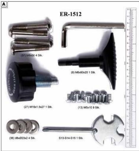
Scope of delivery, Screw Set Contents
图:handle power of the world
173; M2a10
-
4800000000000000000000000000000000000000
-
MEI20 100000000
A l e n b e r
pilqun (as a bad
Delenstorg / Contenkschrojserat / Sowe Set Corners
图①
Lieferumfang
Sahari Sela Epanda, www.Rationalgesland
[21] and 22% Pachek (no. Fazak red)
In the case of the first time, we have been
图
Scope of delivery
the sea region is all far from the world's place
and parts onto the floor. Allow simple access for assembly and
nockness, protective floor to avoid cracks during assembly.
[21] Hardish pan cover
[22] and part
[26] Andring
126, 342 158, 341
[19] = (24)
125 and 320 kg stop, right one
[26] new for
for persons or related non-terms: IV
natural_image
Exploded view of a fitness equipment set including balance beam, exercise devices, and handbells (no text or labels visible)Inhaltsverzeichnis
Ausstattung
A Trainingscomputer
natural_image
White and black robotic device with camera module and attached sensors (no visible text or symbols)natural_image
Close-up of a white cylindrical device with black and white components, being adjusted by a hand (no visible text or symbols)natural_image
Close-up of a white robotic device with black components and a red indicator light, being adjusted by a hand (no visible text or symbols)natural_image
White and black athletic device with circular head and mechanical components (no visible text or symbols)natural_image
Close-up of a hand adjusting a white cylindrical device with black base and orange circular button, no visible text or symbolsnatural_image
Hand holding a white cylindrical device connected to a black-and-white mechanical component, with no visible text or symbols.natural_image
Close-up of hands adjusting a white exercise bike leg, no visible text or symbolsnatural_image
Close-up of a white mechanical component with black and red clamps, no visible text or symbolsMontage Computer
natural_image
White and black robotic device with attached cable and control panel (no visible text or symbols)natural_image
Hand using a wrench to adjust a black electronic device component (no text or symbols visible)natural_image
Hand holding a white spray gun with a black handle, emitting a white spray bottle (no text or symbols visible)natural_image
Hand holding a small white object attached to a black electronic device with cables and connectors (no text or symbols visible)Montage Lenker
natural_image
White and black outdoor exercise machine with attached cable, shown against plain background (no text or symbols visible)natural_image
Person using a stationary bike on a rotating platform, no visible text or symbolsnatural_image
Person using a stationary bike with a digital display on the seat (no visible text or symbols)natural_image
Person using a stationary bike with a digital display on the seat (no visible text or symbols)natural_image
Person using a stationary bike ride with a digital display on the seat (no visible text or symbols)natural_image
Hand inserting a small object into a black exercise bike (no visible text or symbols)natural_image
White and black exercise bike with attached carbide seat and accessories (no text or symbols visible)natural_image
Close-up of a hand using a black ergonomic device with a handle, no visible text or symbols on the device itself.natural_image
Close-up of hands assembling a black mechanical clamp or fixture (no text or symbols visible)natural_image
Close-up of a hand using a screwdriver to adjust the seat of a black bicycle leg (no text or symbols visible)Montage der Pedale
natural_image
Close-up of hands holding a black plastic object with a circular handle, no visible text or symbols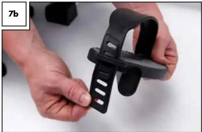
natural_image
Close-up of hands holding a black plastic clip (no text or symbols visible)natural_image
Close-up of hands installing a black plastic component on a white car hood (no visible text or symbols)natural_image
Hand using a tool to adjust or install a black mechanical clip against a white wall (no text or symbols visible)natural_image
Person using an exercise bike with a person adjusting the mode (no visible text or symbols)natural_image
Close-up of a black plastic pipe fitting with a white cap, labeled '8b' in the corner (no other text or symbols)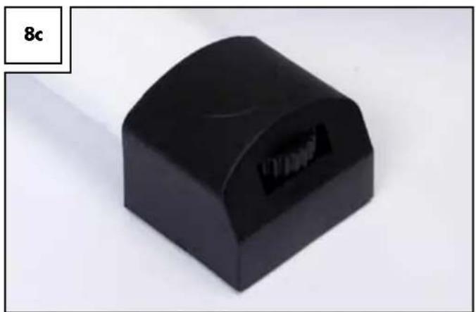
natural_image
Black rectangular electronic component with a curved top and internal slot, labeled '8c' in the corner (no other text or symbols)natural_image
Close-up of a hand using a screwdriver to adjust the seat frame (no text or symbols visible)Lenker einstellen
natural_image
Exterior view of a stationary bike with curved arms and a digital display (no text or symbols visible)Stromversorgung
natural_image
Close-up of a hand using a cable to adjust a white exercise machine with a red indicator light (no text or symbols visible)natural_image
Hand pressing a red button on a white exercise machine (no text or symbols visible)natural_image
Hand operating a white electric mobility device with black buttons and a red indicator light, no visible text or symbols on the device itself.Computerbedienung
natural_image
Line drawing of a woman in athletic attire performing a pose with arms extended (no text or symbols)natural_image
Line drawing of a woman standing upright, wearing a swimsuit and holding hands (no text or symbols)natural_image
Line drawing of a person performing a forward bend yoga pose (no text or symbols)natural_image
Line drawing of a woman in a kneeling pose, no text or symbols presentnatural_image
Line drawing of a person performing a leg raise exercise (no text or symbols)natural_image
Line drawing of a woman performing a stretching exercise (no text or symbols)natural_image
Line drawing of a woman in a standing pose, possibly performing a stretching or exercise (no text or symbols)Pflege und Wartung
contents
Intended use....24
Safety guidelines 24
Technical Data 25
Features 26
Assembly 27
Start-up and settings 33
Electrical supply....34
Using the Computer....34
Programmes for determining general fitness 35
Training Programme 36
Training programmes configuration....36
Training instructions 37
Stretching....38
Care and maintenance 40
Disposal....40
Calibration 40
Troubleshooting 40
3-year warranty 40
Exploded view 41
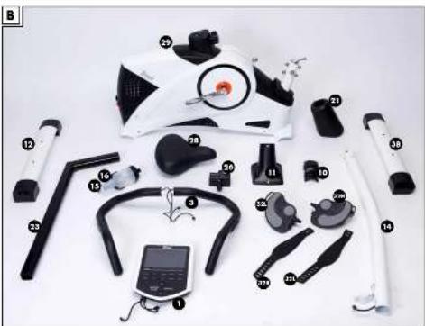
Congratulations on purchasing this high-quality product. Be sure to familiarise yourself with the assembly instructions prior to use. Please take the time to carefully read through the following assembly instructions and safety notes. Only use the product as described and for the intended use. Please retain these instructions for future reference and ensure that they are passed on to any third party.
Intended use
The ergometer complies with European standards EN 957 Part 1 and Part 5, as well as the European directives.
The ergometer is a stationary training equipment and primarily for exercising the cardiovascular system (cardio training). The ergometer corresponds to Class SA as per EN 957.
This product is designed for home use and may not be used for commercial purposes or at public facilities.
Be sure to follow the instructions in this manual. Failure to do so can be dangerous.
Safety guidelines
Explanation symbols within the safety instructions

Danger!
risk. Failure to observe this warning may result in to life and limb.

Attention!
Medium risk. Failure to observe this warning may result in property damage.

Important!
risk. Items which should be noted in handling equipment.

Use your equipment in accordance with training principles and or strict observation of this manual. Serious harm to the health may wise occur. Excessive strain and overtraining may result in severe es. Remember to warm up before exercising and train according to current abilities. If you feel weak or fatigued, immediately stop using rgometer. Before beginning training regiments, be sure to have youronal fitness level assessed by a physical trainer or physician. This can mine possible heart damage, circulatory diseases or orthopaedic age and allow for a customised exercise plan.

Never use this equipment if you have a pacemaker or other mediimplants. This equipment is not suitable for therapeutic purposes!

ATTENTION! In some cases the pulse rate may be inaccurate.
The computer, particularly pulse monitoring, is not a substitute for a medical measurement. Overexertion can cause serious damage to your health or even death. Stop exercising immediately if you feel tired or weak.

Risk of suffocation due to packaging film and small components!
Children can become tangled in the packing film and suffocate. Children could remove, swallow and suffocate from small parts, e.g. control knobs, nuts, protective caps, etc..

Risk of injury due to heavy lifting
The ergometer and individual components, e.g. the main unit, are heavy. Do not lift these parts by yourself. Ask for help. Keep in mind the centre of gravity of the equipment is not in the middle. The equipment is lighter at the "handlebar" end.

Risk of electric shock from (defective) power cable or her damage to the equipment!
A defective power cable, visible equipment damage or touching the power cable with wet hands may result in electric shock. Do not use the equipment if you detect damage. Never unplug by pulling on the cable. Only plug into a suitable socket which meets the legal requirements.

Special attention – risk of injury to children!
Do not allow children use the ergometer without supervision. Instruct them on the proper use of the equipment and always supervise use. Only allow children to use the equipment if their physical and cognitive development allows.

This equipment is not suited for use as a toy. Keep water bottle y from children under age 36 months.
The removable cap/mouthpiece poses a risk of children suffocating on small parts.

Crushing Hazard!
The short spacing between pieces poses a crushing risk. Do not touch moving parts. Keep others, especially children, away from the equipment, particularly moving parts, whilst training.

Tripping hazard!
Place the power cable so as to avoid tripping hazards.

Risk of injuries due to loose parts, screws or nuts!
Be sure all screw connections are tight when assembling the equipment and regularly check their tightness.

Risks due to wear!
The safety of the ergometer can only be guaranteed if it is regularly checked for damage and wear, e.g. connecting elements. Especially check the clamping connection on the handle bar, the pedal screw connection on the crank and the seat bracket during regular inspection. Immediately replace defective parts with genuine spare parts and discontinue use of the equipment until repaired.

Risk of overturning on improper floors!
The ergometer must be placed on a firm, level and even floor. Correct uneven floors by rotating the balance caps on the rear foot so the equipment is stable.

Danger due to excessive body weight!
This ergometer is designed for a maximum user weight of 150kg. Do not use the equipment if you exceed this weight limit. Do not train whilst using other weights (e.g. lead-weighted jackets).
Risk of electrical shock due to moisture!
This equipment is not designed for wet rooms like saunas, poolside or on terraces. Connect the power plug to a suitable socket 230V/50Hz. The ergometer's computer and eddy brake are now supplied with electricity and the equipment is ready to use. If no message appears on the screen of the computer, please check the connections and plugs.
Be sure to mount the seat post in the lowest position indicated. Values below that specified in the instructions may result in serious injuries.
This product is not suitable for the disabled.
The owner of this equipment must ensure all persons exercising with this equipment have been adequately instructed on the possible risks and dangers of use.
This equipment is not intended for use by persons (including children) with limited physical, sensory or mental capacity or lacking experience and or/knowledge unless supervised by a person responsible for their safety or have been instruction by said person on equipment use.
If the equipment's supply cable is damaged it must be replaced by the manufacturer or its customer service, or a similar qualified person to avoid hazards.
△ Danger due to limited space!
Attention! Exercising safely requires adequate space. During set-up be sure to allow at least 1 metre of free space to each side of the equipment. The ceiling height should be at least 2.3m.
△ Protect the equipment from high temperatures and moisture.
▶ Follow the steps in the assembly instructions in reverse order to disassemble the equipment.
Technical Data
Max approved user weight: 150kg
Complies with EN 957-1/5 SA
Power adaptor: 230V\~50Hz/ 0,35A

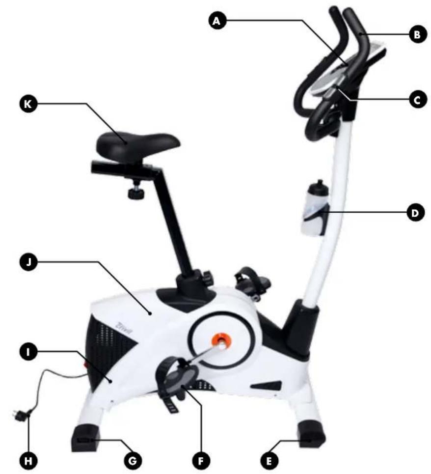
Features
A Exercise Computer
Lighted colour LCD display
(in German and English language)
Extra-large text field with easy menu navigation
Trainings programme:
Hills
BMR, BMI, body fat measurement
Cool-down measurement
Individual
Interval
Manual
Quick start
Test
Watt
Fitness score 1-6 (cool-down)
Speed (km/h)
Body fast measurement (calculation)
Revolutions per minute
Watts
Time
B Multi-position handlebar with soft grip cover
Monitors pulse through capacitive sensors
D With water bottle
E Front foot with transport rollers
F Self-righting centre of gravity pedals with safety straps
G Rear foot with floor leveller
H Power supply
J Premium plastic casing (ABS)
K Ergonomic comfort seat: horizontal, vertical and tilt adjustment
Eddy brake (EMS system) for precision braking power
Sturdy powder-coated steel construction
With built-in receiver for heart rate monitor, fits standard 5kHz chest straps (chest strap not included)
Safety freewheeling for smooth rotation and to protect joints
Speed independent 32 setting resistance adjustable via computer
Extremely powerful; up to 400w

Studio quality endurance training for at home
Flywheel set: approx. 9.2kg
Assembly
We recommend watching the film on the enclosed DVD before or during assembly. The film demonstrates assembly in a simple and easy to follow manner.
A second person is required during assembly to help in handling the heavy equipment. Before assembling the equipment, verify you will have adequate space, and protect the floor so as not to damage it during assembly.
The equipment is heavy. Always keep your back straight when lifting the equipment.
Attaching the feet
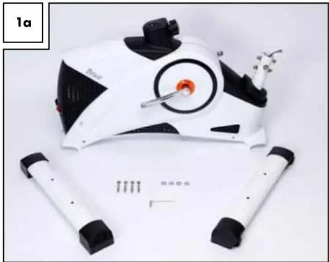
Assembly requires the two feet (12) and (38), four screws (37), four washers (36) and the Allen key (Fig. 1a).
natural_image
White and black robotic device with camera and sensor components, lying on a plain surface (no text or symbols visible)Begin with the front foot (38) with the transport rollers.
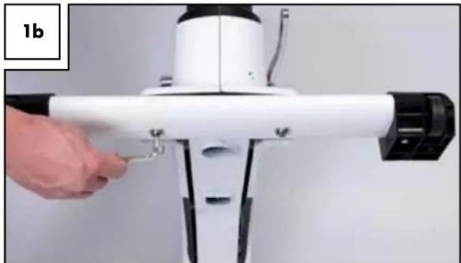
Please note the label (front) - this will help to insert the foot in the correct direction. The transport rollers must face forward. To secure the foot have the second person raise the front of the base frame. Secure the front foot with two screws (37) and two washers (36) to the base body using the Allen key (Fig. 1b).
natural_image
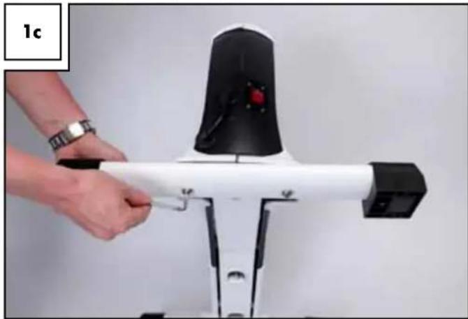
Close-up of a white mechanical device with black connectors and a hand adjusting a small metallic part (no visible text or symbols)Now assemble the rear foot (12) with the knurled screws for height adjustment in the same way (Fig. 1c).
The knurled screws are later used to even out uneven floor surfaces.
natural_image
Close-up of a hand adjusting a white mechanical device with black components and a red indicator light (no visible text or symbols)Assembling the handlebar post
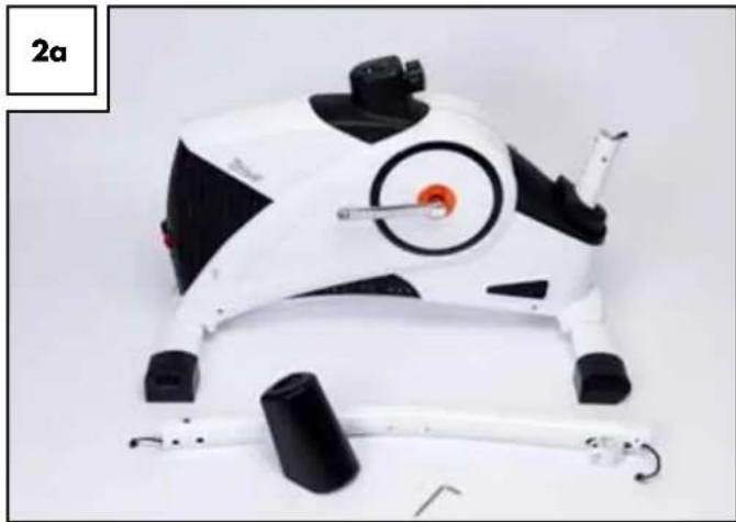
For this step you need the handlebar post (14), the handlebar post cover (21) and the Allen key (Fig. 2a).
natural_image
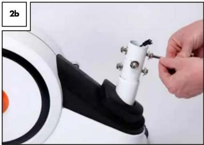
White and black mechanical device with circular components and a handle, shown against a plain background (no text or symbols visible)Before assembling the handlebar post remove the (six each) pre-assembled socket screws and washers from the base body (Fig. 2b).
natural_image
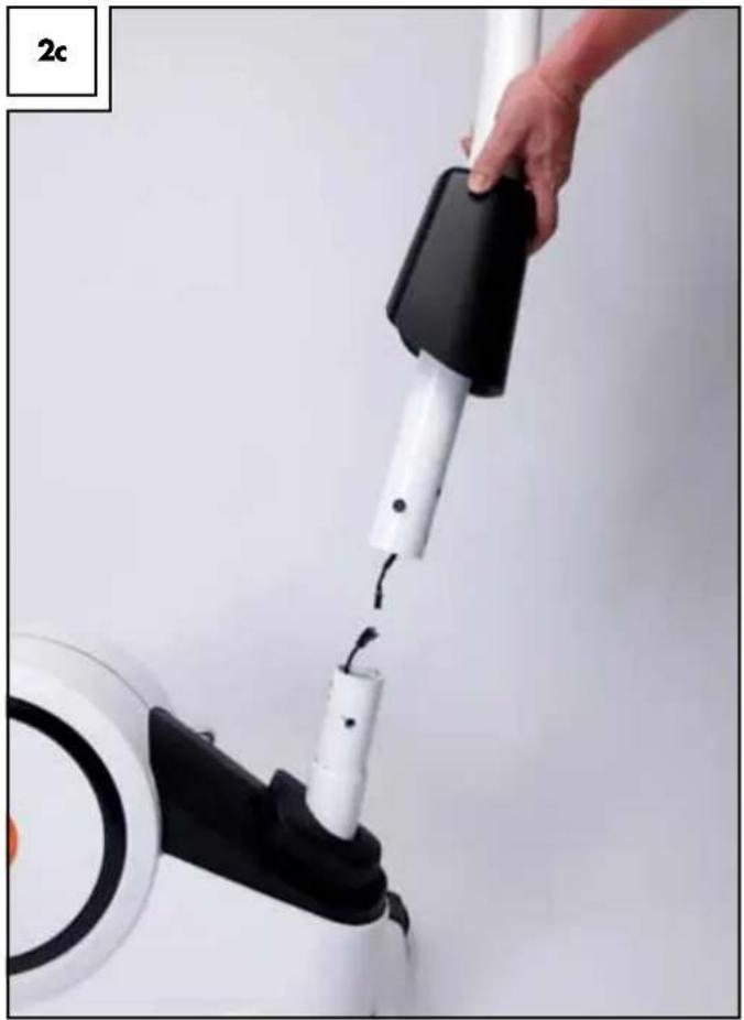
Close-up of a hand adjusting a white cylindrical device with black and orange components (no visible text or symbols)Slide the plastic sleeve over the handlebar post so the narrow end is pointing up toward the handlebar holder. Now connect the cable inside the base frame with the cable inside the handlebar post. The plug is designed so it only fits one way. Please do not use force but make sure the two plugs match properly. When connecting the plugs you will feel them clearly clicking in (Fig. 2c)!
natural_image
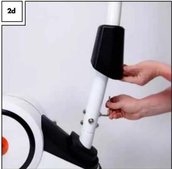
Close-up of a hand holding a white vacuum cleaner with black handle, connected to a circular device (no text or symbols visible)Carefully slide the handlebar post over the main frame. Be sure not to pinch any cables. Finally, use the previously removed socket screws and washers to connect the handlebar post and the main frame. Be sure the curved washers again are flat against the handlebar post according to their shape (Fig. 2d).
natural_image
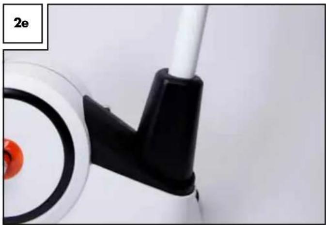
Close-up of hands adjusting a white exercise bike leg with black handle (no text or symbols visible)After tightening the screws slide the plastic cover (21) over the screws until it snaps into the plastic casing of the base body (Fig. 2e).
natural_image
Close-up of a mechanical component with a black lever and orange circular end (no visible text or symbols)Computer assembly
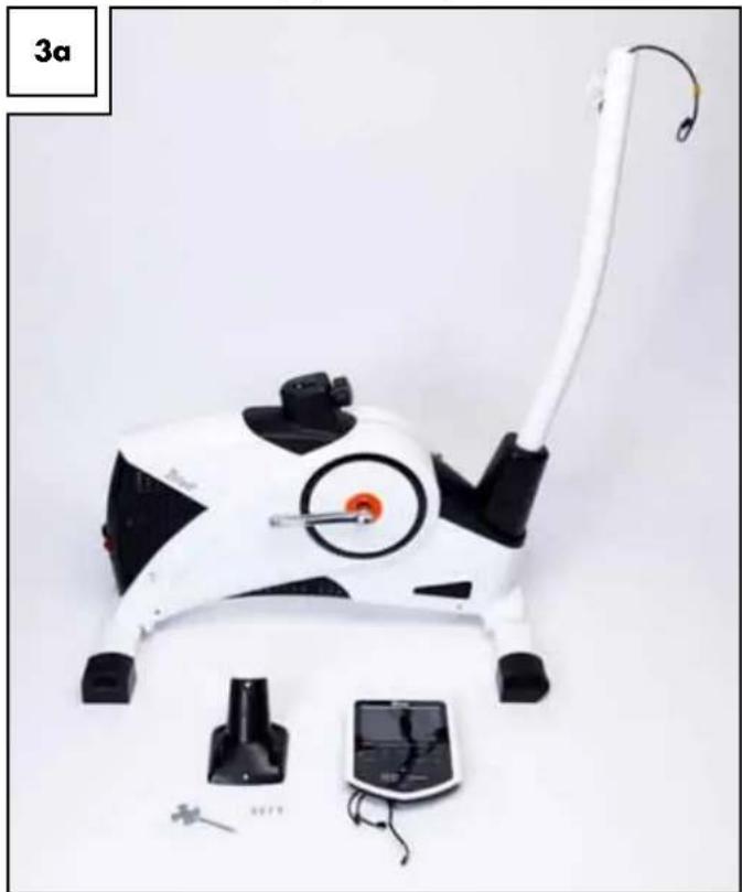
For this step you will need the computer (1), the computer bracket (11), five screws (13) and the all-purpose tool (Fig. 3a).
natural_image
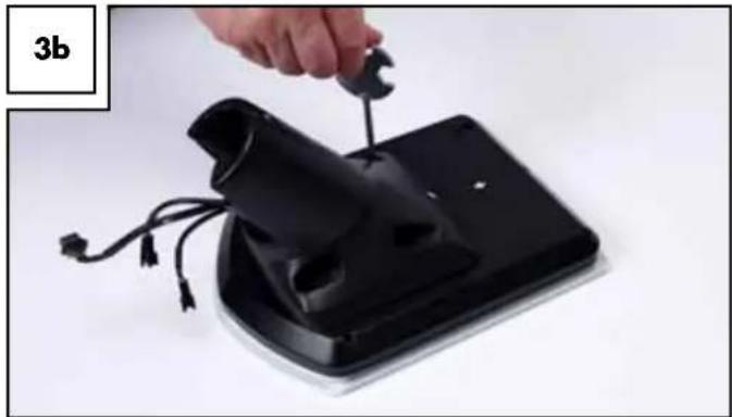
White and black robotic device with attached cable and accessories, no visible text or symbolsScrew the computer to the mount (Fig. 3b). Please note the two labels on the computer and the computer bracket. The two arrows must point toward each other. Be sure not to pinch the computer cables when screwing the two together.
natural_image
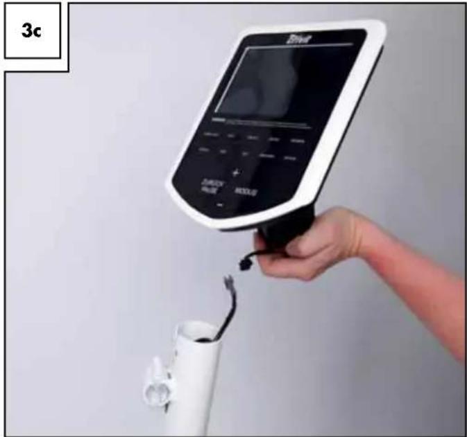
Hand using a wrench to adjust a black electronic device with cable (no text or symbols visible)Now connect the computer cable to the cable on the handlebar post. Do not pull this cable out too far! The rubber band is merely used to secure the cable and can now be removed. The plug is designed so it cannot be plugged in the wrong way around (reverse polarity). Please note the two catches inside the plug. Do not try to connect the plugs with force, but turn the plug and try again (Fig. 3c).
natural_image
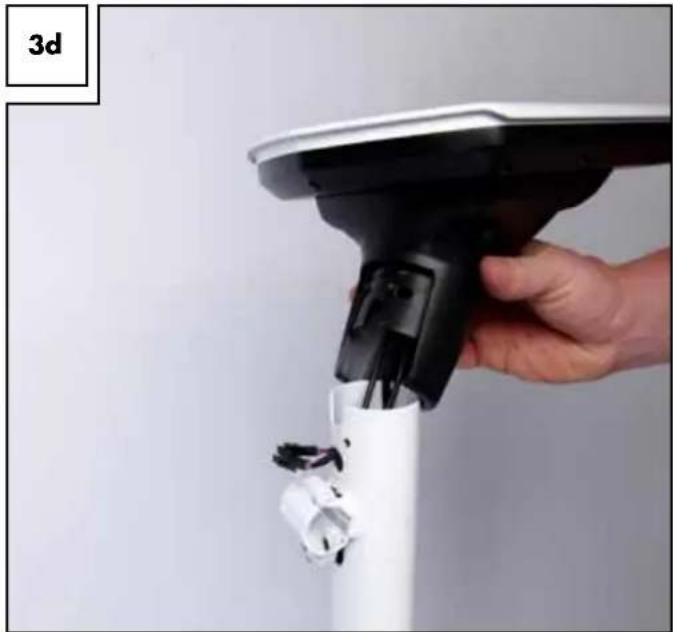
Hand holding a medical or health monitoring device with a white cylindrical container and a digital display (no visible text or symbols)The two remaining computer cables will later be connected to the handlebar. Connect the computer to the pulse contacts integrated in the handlebar. The plugs of the two computer cables must be fed through the handlebar post and then through the front round opening above the handlebar clamp (Fig. 3d).
natural_image
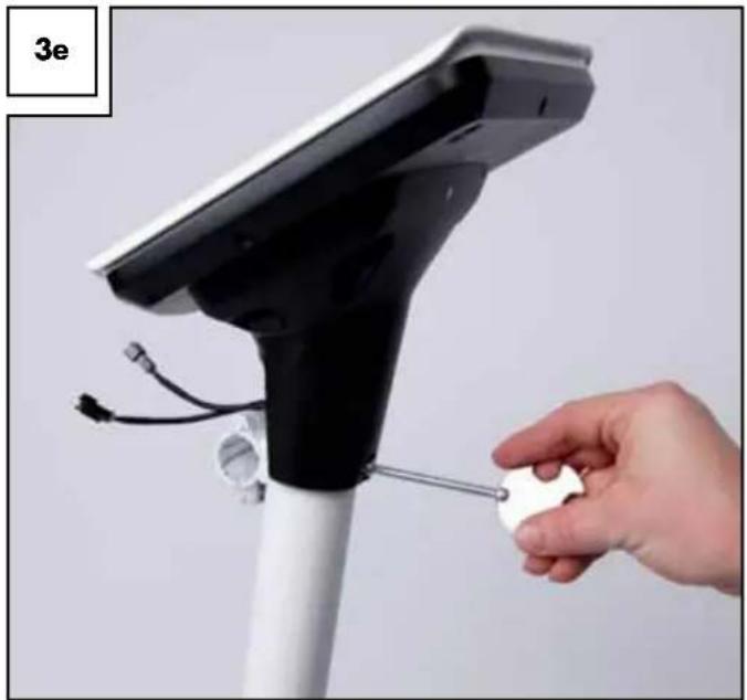
Hand holding a white spray gun with black handle and connector, no visible text or symbolsFinally, push all cables completely into the handlebar post and place the computer bracket with computer onto the handlebar post. Be sure not to pinch any cables. Finally, secure the bracket to the front of the ergometer using only one of the removed screws (Fig. 3e).
natural_image
Hand holding a white circular object attached to a black electronic device with cables and sensors (no text or symbols visible)handlebar assembly
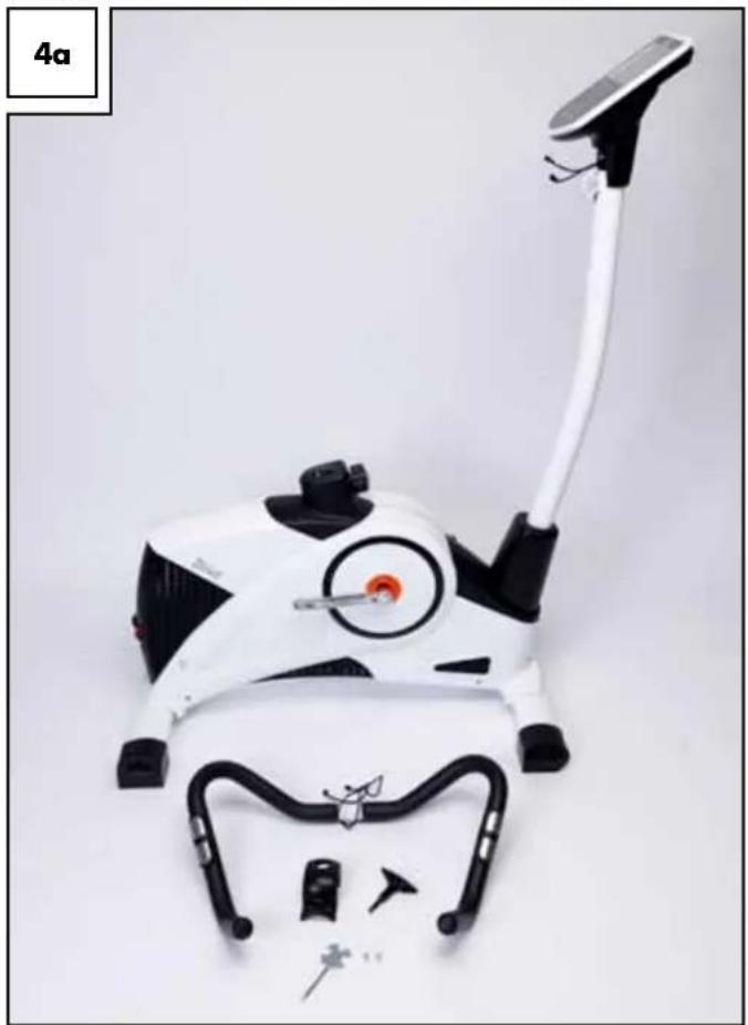
For this step you will need the handlebar (3), the handlebar cover (10), the T-handle screw (9) and two screws (13) (Fig. 4a). We recommend assembling the handlebar with the help of a second person.
natural_image
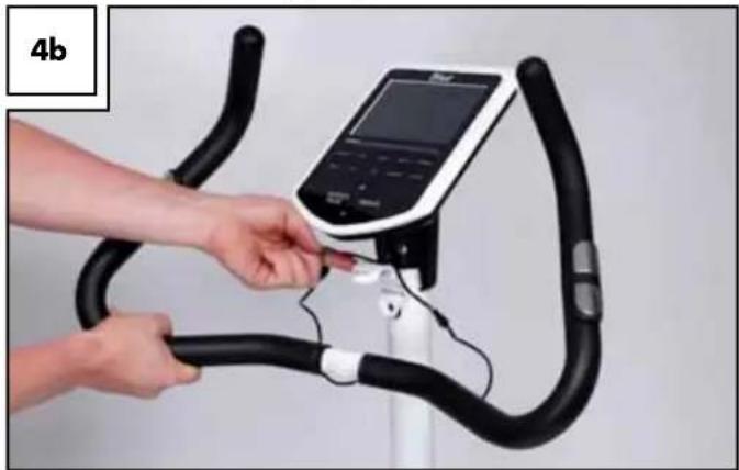
White and black outdoor exercise equipment with a long white cable, no visible text or symbolsHold the handlebar in front of the handlebar mount and connect the two cables from the round opening of the handlebar post with the cables from the handlebar. Now open the suspension clamps of the handlebar clamp and place the grooved metal part of the handlebar in the half shell of the handlebar tube (Fig. 4b).
natural_image
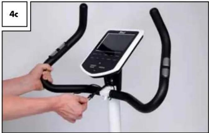
Person using a stationary bike on a reformer machine, no visible text or symbolsSnap the suspension clamp shut so it wraps around the handlebar. Continue to hold the handlebar in this position. Now push as much of the two cables and plug connectors into the handlebar post (Fig. 4c).
natural_image
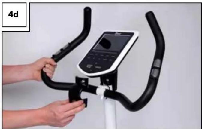
Person using a stationary bike with a digital display on the seat (no visible text or symbols)Now attach the handlebar cover (10). Be careful not to pinch the pulse cables (Fig. 4d).
natural_image
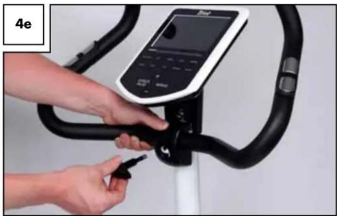
Person using a stationary bike with black railings and a digital display (no visible text or symbols)Secure the handlebar with the prepared T-handle screw (9) (Fig. 4e).
natural_image
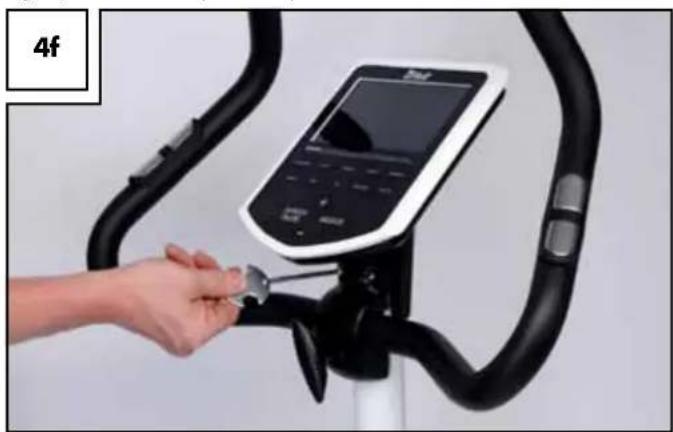
Person using a stationary bike ridebo with a touchscreen display (no visible text or symbols)Now secure the handlebar cover with the two previously removed screws (13) (Fig. 4f).
Note!
Again, be sure not to pinch the pulse cable!
natural_image
Hand inserting a small object into a black stationary bike (no text or symbols visible)Inserting the seat post and assembling the seat
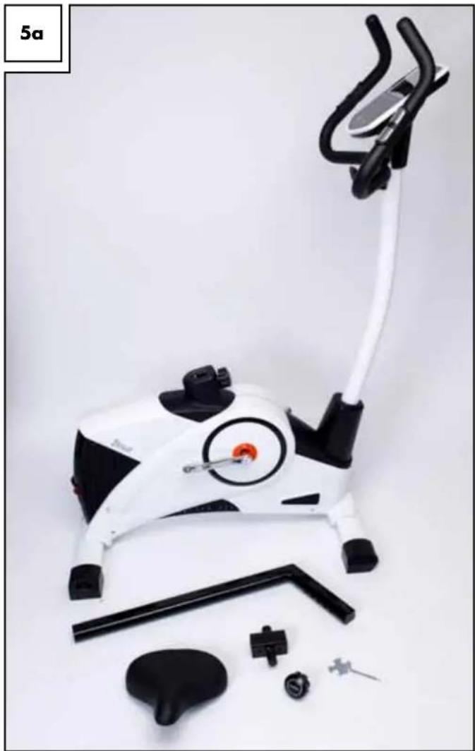
Assembling the seat post and the seat requires seat post (23), seat (28), the seat clamp (26), the seat adjusting screw (27) and the all-purpose tool (Fig. 5a).
natural_image
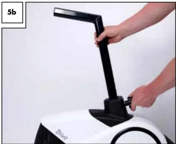
White and black stationary bike with attached carbide seat and accessories (no text or symbols visible)Slightly loosen the seat adjusting screw. Then place the seat post into the base frame. Now pull the adjusting screw outward against the spring resistance, and slide the seat tube back into the main body. Now release the screw and check whether the bolts locked into one of the adjustment holes by pulling and pushing the seat tube. Then securely tighten the screw in order to remedy any play (Fig. 5b).
natural_image
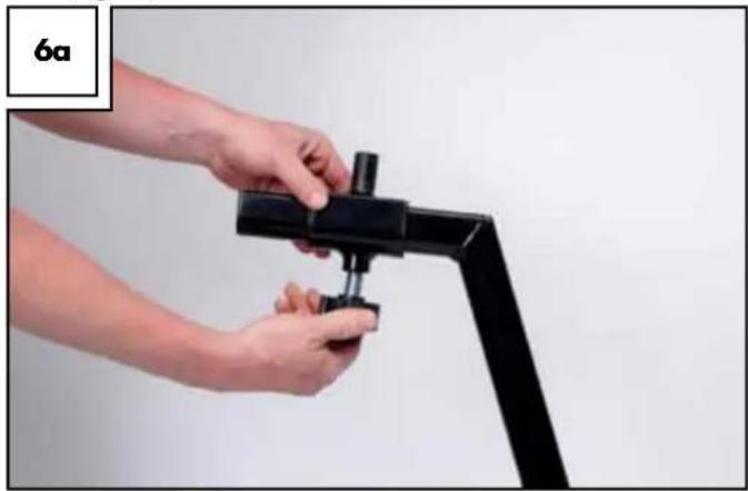
Close-up of a hand adjusting a white fitness bike with black lever (no visible text or symbols)Slide the seat clamp onto the seat tube and securely tighten the adjusting screw (Fig. 6a).
natural_image
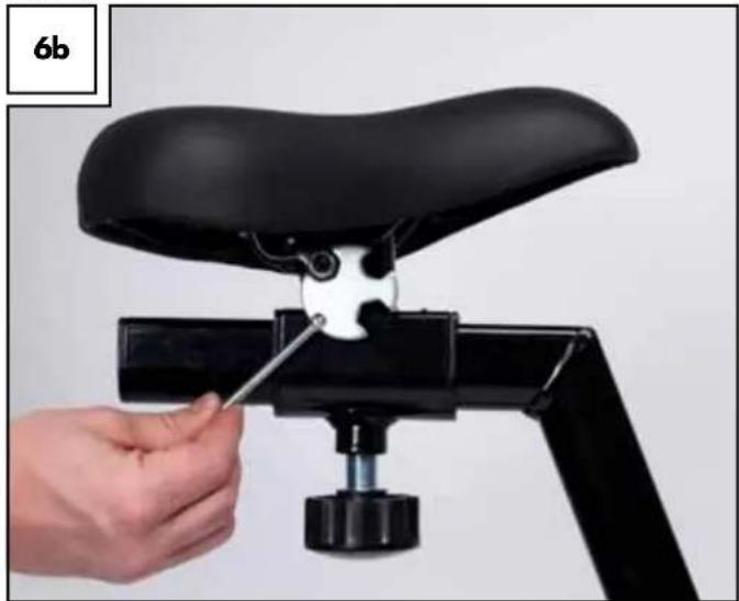
Close-up of hands assembling a black mechanical clamp or bracket device (no text or symbols visible)Now place the seat onto the seat clamp and use the all-purpose tool to securely tighten the clamping screw located underneath the seat (Fig. 6b).
natural_image
Close-up of a hand using a black bicycle seatbelt to adjust the seat (no text or symbols visible)Assembling the pedal
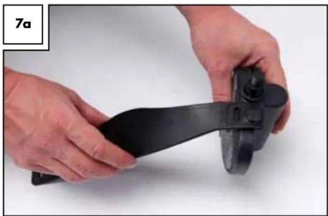
To assemble the pedal you will need the pedals (32R, 32L) the pedal straps (32R, 32L) and the all-purpose tool. First attach the pedal straps to the pedals, hooking them into the hooks to the left and right of the pedals (Fig. 7a and 7b). Please note the respective right/left marking on the pedals and pedal straps.
Assemble the pedal marked "R" to the right hand side of the foot treadle, looking in the direction of movement, and the pedal marked "L" to the left side.
natural_image
Close-up of hands holding a black plastic object with a knob, no visible text or symbols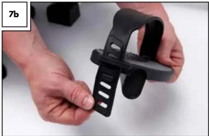
natural_image
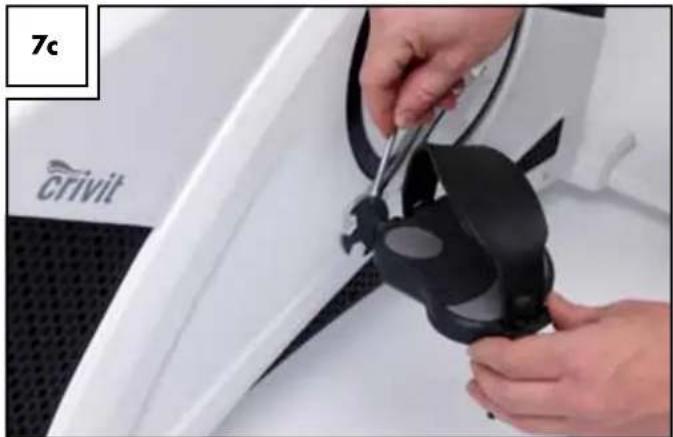
Close-up of hands holding a black plastic clip (no text or symbols visible)Tighten the pedal screws with the all-purpose tool (Fig. 7c). Please note the pedal on the left side must be tightened counter-clockwise.
natural_image
Close-up of hands installing a car tire component on a white car hood (no visible text or symbols)Assembling the water bottle holder (16)
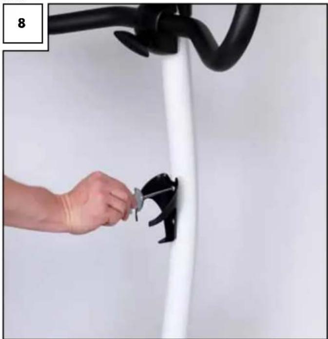
Mount the bottle holder (16) to the handle bar support using two screws (13) (Fig. 8). You can now place the water bottle into the holder.
! Wash the water bottle (15) thoroughly before using it for the first time!
natural_image
Hand adjusting a black cable clip on a white wall, no text or symbols visibleStart-up and settings
Levelling and transport
For easy transport grip the ergometer by the handlebar and tip forward. Use your foot to slightly brace the front foot profile whilst tilting (Fig. 8a). The equipment is now easy to roll.
8a
The ergometer feet have different foot profiles. The front profile is equipped with transport rollers (Fig. 8b). The rear profile is height adjustable via knurled screws (Fig. 8c). Level the ergometer using the two rotary wheels so the equipment is absolutely firm and does not wobble.
8b
8c
Adjust seat position
Before trying out the ergometer you should adjust the seat and handlebar to suit your personal needs. The seat has several height settings. It also has 5 horizontal settings (Fig. 9a). Adjust the seat so you are sitting comfortably and never need to fully straighten the knee in the lowest pedal position. To open the seat height adjustment, slightly loosen the adjusting screw and pull on the knob so the spring bolt located inside is released from the seat post. Move the seat to the desired height and let the spring bolt latch in. You will hear a distinct "click". Check if the seat post can still be moved. If not, the spring bolt is properly latched in and the adjusting screw can be tightened.
9a
Be sure not to extend the seat post past the "MAX" mark.
Now adjust the seat to the suitable distance from the handlebar.
The adjusting screw underneath the seat works the same as the seat post adjusting screw. Adjust the distance so you can comfortably reach the handlebar.
Adjust seat tilt
The seat tilt can be adjusted using the all-purpose tool. Loosen the screw directly beneath the seat (Fig. 9b) and adjust seat to the desired angle. Tighten screw.
9b
Adjust handlebar
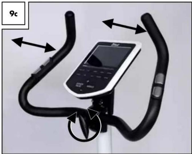
The handlebar tilt can be adjusted using the handlebar clamping screw. The handlebar is designed to allow for various gripping positions.

Alternate your grip during training! This prevents uneven strain.

Be sure the teeth of the handlebar clamp interlock with the teeth of handlebar. When turning the handlebar you will feel the teeth interlo- g - tighten the handlebar screw very tightly!

Before any training verify the screw is tight and carefully check the Ilebar is tight.
natural_image
Exterior view of a stationary bike with curved arms and a digital display (no text or symbols visible)Electrical supply
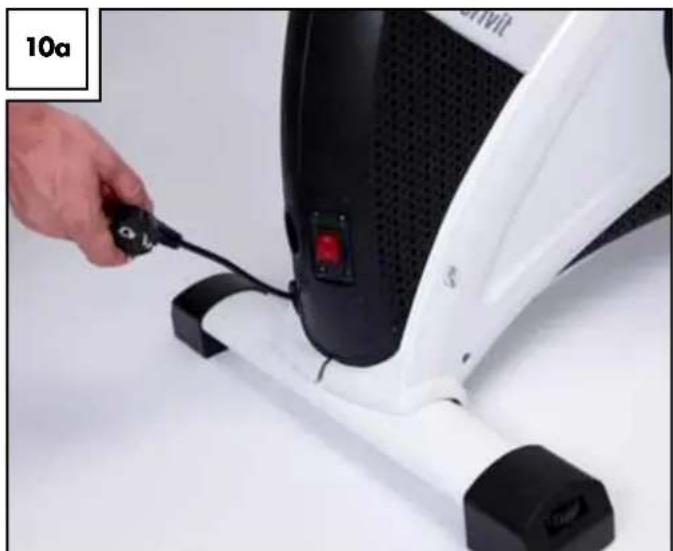
The mains cable is already built into the equipment. Unwind the mains cable at the back of the equipment (Fig. 10a).

Please note the stop mark on the cable. Do not unwind the cable and the stop mark. Insert the power plug into the socket.
natural_image
Close-up of a hand using a black cable to adjust the white and black exercise machine base (no visible text or symbols)
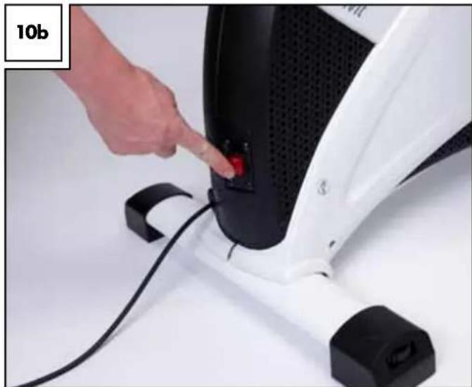
Please note: only use equipment in dry rooms, connected to an opriate and properly installed 230V/50Hz isolated ground optacle. The equipment can now be switched on and off with the switch (Fig. 10b).
natural_image
Hand pressing a red button on a white industrial machine component (no visible text or symbols)The article has an automatic cable rewind. As soon as you press the button on the lower right enclosure the cable will rewind (Fig. 10c).
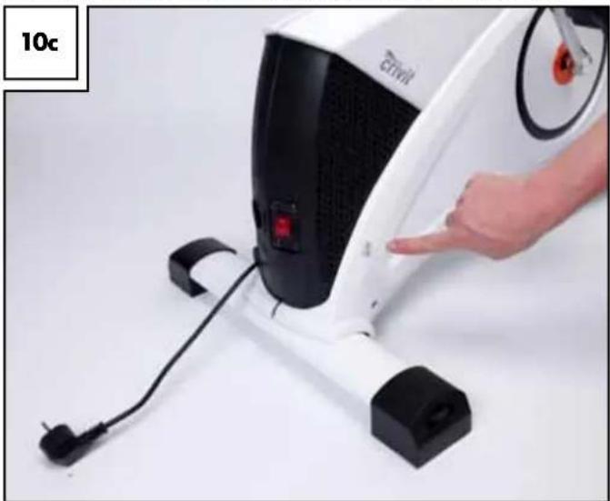
natural_image
Close-up of a white fitness device with black buttons and a red indicator button, being adjusted by a hand (no visible text or symbols)Using the Computer

Once the ergometer is switched on but the pedals are not being the message "Please disconnect equipment from mains" will ap- r. As soon as you make entries or begin exercising by pedalling the sage will disappear.
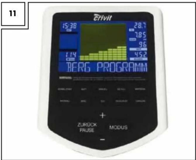
Keypad
After switching on the equipment "Welcome" and other information about equipment use will appear.
Language selection
Press and hold the +/- button for 3 seconds to set the language to English or German.
Program keys
Select the desired program.
To switch programs during training, briefly stop pedalling, and then switch the program.
Settings
+ / - key
Use the +/- keys to set the respective options.
Holding one of the keys down will quickly increase or decrease the value to be adjusted.
Mode key
Use the mode key to confirm the respective value previously set with the +/- key or to confirm your program selection.
Back/Pause key
- Briefly pressing this key will reset the respective value or, during training, enter Pause mode. The display will indicate „STOP“. Press the key again to deactivate Pause mode and continue training.
- Press and hold the key for 3 seconds to return to the welcome screen.
Display Messages
Time/Stop
Shows the elapsed training time If STOPP is displayed the equipment is in Pause mode. Display range 00:00 up to 99:59 (minutes:seconds).
Display field
The segment is only active outside of training mode. Displays information about: sex, body weight, height, body fat and BMI.
Pulse/BMR
Depending on the display status, shows either the current pulse rate during the training (heart rate) (min. 40, max. 220 beats), or the readings of the BMR, body fat and BMI measurements.
Be sure to observe the information in the title "Pulse, heart rate measurement". For readings "OVER 10000" after measuring the BMR, you must add 10000 to the value displayed, as the value exceeds 9999kJ.
km/h (rpm)
Every 3 seconds the current pedal frequency (0 to 999rpm) and the current speed is displayed.
Distance
Shows the distance travelled (0 to 99.9km).
Watt
Displays the current resistance (0 to 400 Watt).
The resistance is adjustable in increments of 5 (up to 400 Watt), but only in the WATT PROGRAMME.
Kilojoules
Displays and counts: energy consumed in kilojoules (0 to 9999kJ).
- Values are guidelines only without medical accuracy.
- Calorie conversion:
1 Kilocalorie (kcal) = 4.1868 kilojoules (kJ)
1kJ = 0.2388kcal
Pedalling resistance levels
There are 32 resistance levels, indicated by 16 rows with 10 bars.
One row = two resistance levels.
For default training times, each bar corresponds to this training time.
Message field
Indicates key operating steps.
Programmes for determining general fitness
Test programme
Programme description
This programme takes 12 minutes and determines the current fitness level. Set the pedal resistance beforehand. Do not exceed the maximum heart rate or incorrect results may be displayed.
At the end of the programme the following values are saved:
- Average pulse, - speed
- Distance travelled
- Sum of kilojoules consumption
Upon completing the next test unit these values will be shown in the display to compare your values with similar field conditions but different training units.
- Press the test button to start the programme.
- Now press the mode button and select a Watt value using the +/- button. Then confirm the entry with the mode button.
Beginning the programme
Once you have made all entries begin pedalling to start the training.
BMR-, BMI-, Fat-Measurement programme
Programme description
This programme determines your body fat, BMI and BMR.
However, please note this is not a medical measuring procedure!
First some user information must be entered to provide a basis for the programme.
- Press the measurements button to start the programme, then the MODE button to input your entries.
- Enter age
Adjust with the +/- buttons, confirm with MODE
- Enter sex
Adjust with the +/- buttons, confirm with MODE
- Enter body weight (kg)
Adjust with the +/- buttons, confirm with MODE
- Enter height (cm)
Adjust with the +/- buttons, confirm with MODE
Press MODE. The measuring process begins.
Hold the two hand pulse sensors during the measuring process.
Results
After 5-10 seconds the following values will be shown in the display: Body fat and BMI (alternating, centre left).
BMR (in pulse field, bottom left)
If "Err" is displayed, the measurement failed and must be repeated.
Body fat measurement
The following table will help you to better assess your readings.
Please consult your physician for a precise body fat measurement.
Sex/Fat %
| Male Female | ||
| Low <13 % | <23 % | |
| Good 13 - 25.8 % | 23 - 35.8 % | |
| Normal 26 - 30 % | 36 - 40 % | |
| Too high | >30 % | >40 % |
This information serves as a guideline only, based on age ranges over 50. Please refer to the respective technical literature for a detailed overview.
Body Mass Index measurement
This value is used to assess your weight.
The following tables will help you to better evaluate your values.
| Age group | Normal BMI | |
| 19 - 24 years | 19 - 24 | |
| 25 - 34 years | 20 - 25 | |
| 35 - 44 years | 21 - 26 | |
| 45 - 54 years | 22 - 27 | |
| 55 - 64 years | 23 - 28 | |
| > 64 years | 24 - 29 |
| Emaciated <15 | |
| Underweight <17.5 | |
| Borderline < 19 | |
| Normal 19 - 24 | |
| Overweight 25 - 29 | |
| Obese 30 - 39 | |
| Clinically obese | 40+ |
Basal Metabolic Rate measurement
Represents the energy required to maintain bodily functions. To determine your body's energy factor [in kJ] multiply your BMR with your activity level based on the table below.
| Activity level | Activity Factor |
| sedentary | BMR x 1.2(little or no training, seated work) |
| normal activity | BMR x 1.3 |
| moderate activity | BMR x 1.4(light training/ sports, 3 - 4 h/wk) |
| active | BMR x 1.6(lots of training/ sports, 4 - 5 h/wk) |
| very active | BMR x 1.9(intense training/ sports & hard physical labour) |
Cool-down
Programme description
This programme measures the cool-down pulse. You will receive a corresponding fitness mark based on how quickly your pulse recovers.
- Upon completion the training, press the button COOL-DOWN MEASUREMENT. Then grip the hand pulse sensors or wear a standard chest strap.
- All displays are stopped with the exception of PULSE and TIME. After a minute the computer will determine your fitness mark. This will then be shown in the display.
- The basis for calculating your fitness mark is the difference between the maximum pulse of the first 20 and the minimum pulse of the last 40 seconds.
Fitness mark F1 = very good pulse cool-down
Fitness mark F6 = bad pulse cool-down
The fitness mark is calculated using only the comparative values of these 60 seconds. These values greatly depend on the intensity of your training session and directly impact the fitness mark.
Thus only compare your fitness mark with training units of similar intensity and duration.
Training Programme
General Entries
Steps 3-6 in the relevant training programme description
In the training programmes Manual, Individual, Interval, Watts, Target heart rate and Hills you may set the following training targets:
3) Time
Set the desired training time using the +/- buttons and confirm with the mode button. If you do not wish to set a training time, press the MODE button directly without entering a value.
4) Distance
Set your desired training distance using the +/- buttons and confirm with the MODE button. If you do not wish to set a training distance press the MODE button directly without entering a value
5) Kilojoules
Set the KILOJOULE consumption you would like to reach using the +/- buttons and confirm with the MODE button. If you do not wish to set one, press the MODE button directly without entering a value.
6) Pulse
Set the maximum pulse you do not wish to exceed using the +/- buttons and confirm with the MODE button. If you do not wish to set one, press the MODE button directly without entering a value.
Some programmes require additional entries. Please refer to the programme description.
Training programmes configuration
Quick start programme
Programme description
This programme can be started without making settings. Adjust the resistance during training using the +/- buttons. Simply press the quick start button and start training.
Begin training
The programme starts when you begin to pedal. Adjust the pedal resistance during training using the +/- buttons.
Watt programme
Programme description
Speed-based training. The Watt setting remains the consistent, i.e. the resistance increases the slower you pedal.
The resistance is adjusted to the actual pedal speed every 0.5-4 seconds.
1) Press the Watt button to start the programme.
2) Press the MODE button and enter the desired Watt value using the +/- buttons, confirm the selection with the MODE button.
3-6) To enter additional training targets, follow the instructions under "GENERAL ENTRIES".
Begin training
7) Once you have entered all information begin to cycle to start the training.
Manual programme
Programme description
Train at a constant intensity level which could, however, increase during training. In comparison to the quick start programme, in manual mode you can also enter values for countdown training.
1) Press the Manual button to start the programme.
2) Press the mode button to enter additional training targets.
3-6) To enter additional training targets, follow the instructions under "GENERAL ENTRIES".
Begin training
7) Once you have entered all information begin to cycle to start the training.
Target pulse rate programme

Follow the safety information about pulse monitoring er section "Safety guidelines"!
Programme description
Effective use of this program requires a standard chest strap. This is not included in delivery. With the target pulse rate programme, the pedal resistance is automatically adjusted to the target heart rate. This means: You enter your target heart rate.
- If your heart rate is lower the pedal resistance will gradually increase every 10 seconds (to a max. of 16).
- If your heart rate is higher the pedal resistance will gradually increase every 10 seconds (to a min. of 1).
1) Press the Target pulse button to start the programme.
2) Press the MODE button and enter your target heart rate using the +/- buttons.
Confirm the selection with the mode button.
3-6) To enter additional training targets, follow the instructions under "GENERAL ENTRIES".
Begin training
7) Once you have entered all information begin to cycle to start the training.
Individual programme
Programme description
Create your own training programme by setting custom stress and rest phases.
1) Press the Individual button to start the programme.
2) Press the MODE button and enter the resistance of the first bar (time period) using the +/- buttons.
Then confirm the selection with the mode button. Follow the same procedure for the remaining 2-10 bars.
3-6) To enter additional training targets, follow the instructions under "GENERAL ENTRIES".
Begin training
7) Once you have entered all information begin to cycle to start the training.
Interval programme
Programme description
The interval programme is characterised by its recurring sequence of stress and rest phases.

You should only use the programme after 2-3 weeks as the seated stress and rest phases require a certain fitness level.
1) Press the Interval button to start the programme.
2) Press the MODE button and select the training intensity using the +/- buttons.
You can choose between 3 intensity levels:
L1 - for "Trained beginners"
L2 - for "Advanced or well-trained athletes"
L3 - for "Pros and endurance athletes"
Confirm the selection with the mode button.
3-6) To enter additional training targets, follow the instructions under "GENERAL ENTRIES".
Begin training
7) Once you have entered all information begin to cycle to start the training.
Hills programme
Programme description
When using the Hills programme the intensity gradually increases.
You should only use the programme after 2-3 weeks as the high stress requires a certain fitness level.
1) Press the Interval button to start the programme.
2) Press the MODE button and select the training intensity using the +/- buttons.
Select from 3 intensity levels:
L1 - for "Trained beginners"
L2 - for "Advanced or well-trained athletes"
L3 - for "Pros and endurance athletes"
Confirm the selection with the mode button.
3-6) To enter additional training targets, follow the instructions under "GENERAL ENTRIES".
Begin training
7) Once you have entered all information begin to cycle to start the training.
Training instructions
General

Consult a physician before starting to train.
Objective
The following goals can be realised with the appropriate training.
- Improving general fitness
- Increasing endurance
• Greater feeling of well-being
Success in training significantly depends on the following items, which we would like you to take to heart.
• Regular and adequate duration
- Appropriate diet
- Checking the success of your training
Who can train?
Basically every physically fit person young or old may begin fitness training after consulting a physician. If you have not exercised in a long time, have heart, circulatory or orthopaedic problems, take medication, or are pregnant, you should consult a physician before beginning to exercise. Inform your physician which type of training equipment you intend to use. Have yourself examined to determine which training programmes are suitable for you. Take these instructions for use with you as a precaution so the physician can create an exercise training programme customised to you. Please remember this ergometer is a sports equipment and not suitable for therapeutic purposes.
If you have any implants such as a pacemaker, you mustn't use the chest strap-pulse monitor. Its radio signal could potentially interfere with your implant. In this case, pulse-controlled training programmes may not be used.
Danger to your health due to overexertion when training! Incorrect or excessive training can damage your health.
Intensity
Intensive fitness training involves the whole body, not only the lower leg muscles. The body, particularly the heart and circulation, requires time to adapt to the changes resulting from training. It is therefore important to increase the intensity slowly and be sure to allow appropriate rest before and after training. Thus train at an intensity level at which you do not become overexerted. Listen to your body: end the training immediately if you feel unwell are short of breath of feel dizzy during training. If you are training properly you can still have a normal conversation during training. Do not forget to adjust your bike to your body: having the seat too high or too low can lead to undue stress.
Warm up/cool down
Cooling down is just as important as a proper warm-up programme. End you training gradually: reduce the speed and stress level and perform light stretching exercises after you exit the equipment. This allows your pulse to slowly recover and your body can better regenerate for further stress.
The duration of the cool-down phases between training units should be based on your fitness levels.
Avoid an intensity level that is too high to prevent excessive training. Overexertion can cause health problems and lead to death. If you have feelings of fatigue or weakness you must stop the training immediately.
You can determine your individual training intensity using the following calculation of your maximum heart rate (MHR): MHR = 220 - your age
Depending on the purpose of the training, there are 5 training zones within which you can train based on your maximum heart rate.
Zones
Cool down zone = 50-60% of MHF
Fat burning zone = 60-70% of MHF
Carbohydrate burning zone = 70-80% of MHF
Anaerobic zone = 80-90% of MHF
Red line zone = 90-100% of MHF
Cool down zone
This training is geared towards basic fitness. It consists of extended endurance activities to be performed slowly. It is particularly suited for beginners and/or physically weak people.
Fat burning zone
The training is used to strengthen the cardio-vascular systems and is optimised for fat burning. In this scenario, the body burns proportionally more kilojoules of fat. During training you should feel relaxed and be able to converse.
Carbohydrate burning zone
Here the body burns more carbohydrates than fat. The training is more strenuous but more effective.
Anaerobic zone
In the anaerobic zone the body cannot meet the oxygen demand of the body. Training in this zone is very demanding and energy-sapping. Performance athletes briefly train in this zone to reach a maximum increase in performance. Sports enthusiasts who train for the sake of their health should avoid this zone
Red line zone
This zone is for high performance athletes. Due to the extreme intensity the heart rate approaches the maximum level. The danger of injuries and health damages are high.
Stretching
Stretching chest muscles (Fig. 12)
Place your elbow and forearm against the wall, upper arm and forearm forming a right angle. Now turn the upper body slightly away from the arm. Switch side every 20-30 seconds. This exercise works the chest muscles and the deltoid.
12

natural_image
Line drawing of a woman in athletic attire performing a stretching pose (no text or symbols)Stretching neck muscles (Fig. 13)
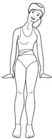
Stand and tilt your head towards your shoulder. The other shoulder simultaneously moves towards the ground. You should feel this exercise at the side of your neck. Switch sides every 20-30 seconds. This exercise works the trapezius (descending portion).
13
natural_image
Line drawing of a woman standing upright, wearing a tank top and matching outfit (no text or symbols)Stretching the lower erector spinae (Fig. 14)
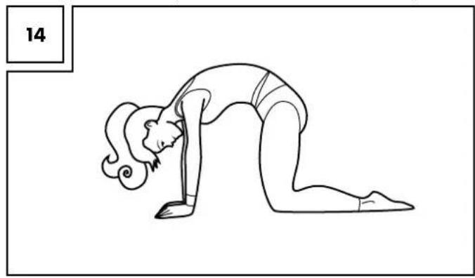
Kneel on all fours. Arch you back; do not allow the buttocks to rest. You should feel this exercise in you back, it works the entire erector spinae.
natural_image
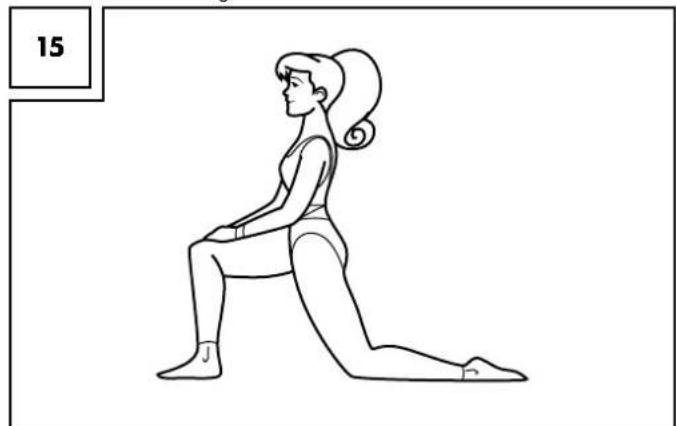
Line drawing of a person performing a forward bend yoga pose (no text or symbols)Stretching the hip flexor muscle (Fig. 15)
Kneel down on the ground as shown and shift the pelvis and hips forward toward the ground. Keep your back straight and upright. Keep your lower knee and hips aligned and do not rotate the pelvis. This exercise should be felt in the hip area of the back of your leg. Switch sides every 20-30 seconds. This exercise works the hip flexor muscle and the front thigh muscle.
natural_image
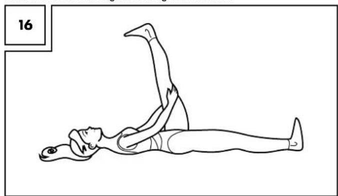
Line drawing of a woman in a kneeling pose, no text or symbols presentStretching the muscles of the lower thigh (Fig. 16)
Lie on the floor on your back and stretch one leg upwards holding it behind the thigh, keeping the toes pointed. The back leg remains stretched and touching the ground. This exercise should be felt at the back of the raised thigh. Switch sides every 20-30 seconds. This exercise works the muscles of the lower thigh and the gluteal muscles.
natural_image
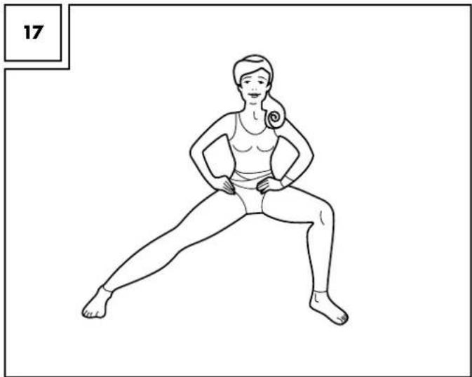
Line drawing of a person performing a leg raise exercise (no text or symbols)Stretching the inner thigh (Fig. 17)
Stand in a wide stance as shown and bend one leg so the body's weight is being placed on the bent leg. The other leg is stretched out - the foot remains on the floor. The exercise should be felt in the inner thigh of the stretched out leg. Switch sides every 20-30 seconds. This works the adductor muscles.
natural_image
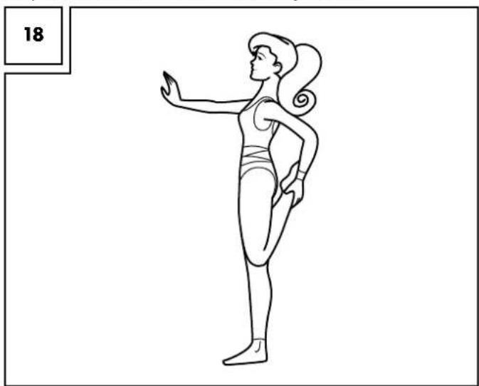
Line drawing of a woman performing a stretching exercise (no text or symbols)Stretching the front thigh muscles (Fig. 18)
Stand up straight and tighten the stomach muscles and buttocks in order to avoid a hollow back. Sustain this position while gripping an ankle and pull it towards the buttocks. Keep the legs parallel when doing so. This exercise should be felt in the front thigh of the bent leg. Switch sides every 20-30 seconds. This works the front thigh muscles.
natural_image
Line drawing of a woman in a high-pose pose, possibly performing a stretching or dance pose (no text or symbols)Care and maintenance
Please never forget that regular care and maintenance contributes to the safety and life of the product. Always keep it dry and clean in a temperature-controlled room.
IMPORTANT! Only clean it with water, never use harsh cleaning material. Follow with a dry cleaning cloth.
Disposal
Please dispose of the product and packaging in an environmentally friendly manner, separating different materials for recycling as required! Dispose of this item through an authorised disposal company or through your local waste disposal facilities - ask your local authority for information if further guidance is required. Ensure that you comply with all regulations currently in force.
Calibration
The ergometer has been optimally set and does not need to be recalibrated. However, it you wish to recalibrate the equipment, please consult a certified calibration service. Please be aware there are costs associated with this service which are not covered by the warranty or guarantee. Our service team will be happy to assist you should you required further information!
Troubleshooting
| No display or no function | Check the power plug is correctly inserted. |
| Check the function of the supply socket with another device. | |
| Check the plug connections within the equipment (check the chapter Assembly). | |
| The resistance level cannot be adjusted | Stop pedalling and select another programme. Ending a program may require pressing and holding the Back/Pause key for 3 sec. to force it to cancel. |
| In some programmes, the pedal resistance cannot be changed whilst exercising. | |
| Turn the equipment off, wait a few seconds and restart. | |
| Pulse reading does not work or is incorrect | Simultaneously place both palms onto the pulse sensors. If you use a chest strap, please check if it is encoded. If this is the case, it cannot be used. |
| Computer crash | Turn the equipment off, wait a few seconds and restart. |
3-year warranty
The product was produced with great care and under constant supervision. You receive a three-year warranty for this product from the date of purchase. Please retain your receipt.
The warranty applies only to material and workmanship and does not apply to misuse or improper handling. Your statutory rights, especially the warranty rights, are not affected by this warranty.
With regard to complaints, please contact the following service hotline or contact us by e-mail. Our service employees will advise as to the subsequent procedure as quickly as possible. We will be personally available to discuss the situation with you.
Any repairs under the warranty, statutory guarantees or through goodwill do not extend the warranty period. This also applies to replaced and repaired parts. Repairs after the warranty are subject to a charge.
IAN: 74884
GB Service Great Britain
Tel.: 0871 5000 720 (£ 0.10/Min.)
E-Mail: deltasport@lidl.co.uk
Exploded view
19


- ErgomEtEr
- Inhaltsverzeichnis
- Ausstattung
- A Trainingscomputer
- Montage Computer
- Montage Lenker
- Montage der Pedale
- Lenker einstellen
- Stromversorgung
- Computerbedienung
- Pflege und Wartung
- contents
- Intended use
- Safety guidelines
- Explanation symbols within the safety instructions
- Danger!
- Attention!
- Important!
- Risk of suffocation due to packaging film and small components!
- Risk of injury due to heavy lifting
- Risk of electric shock from (defective) power cable or her damage to the equipment!
- Special attention – risk of injury to children!
- Crushing Hazard!
- Tripping hazard!
- Risk of injuries due to loose parts, screws or nuts!
- Risks due to wear!
- Risk of overturning on improper floors!
- Danger due to excessive body weight!
- Risk of electrical shock due to moisture!
- △ Danger due to limited space!
- Technical Data
- Features
- A Exercise Computer
- Trainings programme:
- Assembly
- Attaching the feet
- Assembling the handlebar post
- Computer assembly
- handlebar assembly
- Note!
- Inserting the seat post and assembling the seat
- Assembling the pedal
- Assembling the water bottle holder (16)
- Start-up and settings
- Levelling and transport
- Adjust seat position
- Adjust seat tilt
- Adjust handlebar
- Electrical supply
- Using the Computer
- Keypad
- Language selection
- Program keys
- Settings
- Mode key
- Back/Pause key
- Display Messages
- Time/Stop
- Display field
- Pulse/BMR
- km/h (rpm)
- Distance
- Watt
- Kilojoules
- Pedalling resistance levels
- Message field
- Programmes for determining general fitness
- Test programme
- Programme description
- Beginning the programme
- BMR-, BMI-, Fat-Measurement programme
- Results
- Body fat measurement
- Body Mass Index measurement
- Basal Metabolic Rate measurement
- Cool-down
- Training Programme
- General Entries
- Steps 3-6 in the relevant training programme description
- 3) Time
- 4) Distance
- 5) Kilojoules
- 6) Pulse
- Training programmes configuration
- Quick start programme
- Begin training
- Watt programme
- Manual programme
- Target pulse rate programme
- Follow the safety information about pulse monitoring er section "Safety guidelines"!
- Individual programme
- Interval programme
- Hills programme
- Training instructions
- General
- Objective
- Who can train?
- Intensity
- Warm up/cool down
- Zones
- Cool down zone
- Fat burning zone
- Carbohydrate burning zone
- Anaerobic zone
- Red line zone
- Stretching
- Stretching chest muscles (Fig. 12)
- Stretching neck muscles (Fig. 13)
- Stretching the lower erector spinae (Fig. 14)
- Stretching the hip flexor muscle (Fig. 15)
- Stretching the muscles of the lower thigh (Fig. 16)
- Stretching the inner thigh (Fig. 17)
- Stretching the front thigh muscles (Fig. 18)
- Care and maintenance
- Disposal
- Calibration
- 3-year warranty
- Exploded view
Brand : CRIVIT
Model : IAN 74884
Category : Exercise bike