
PPR 4 A1 - Déboucheur de tuyaux POWERFIX - Free user manual and instructions
Find the device manual for free PPR 4 A1 POWERFIX in PDF.


User questions about PPR 4 A1 POWERFIX
0 question about this device. Answer the ones you know or ask your own.
Ask a new question about this device
Download the instructions for your Déboucheur de tuyaux in PDF format for free! Find your manual PPR 4 A1 - POWERFIX and take your electronic device back in hand. On this page are published all the documents necessary for the use of your device. PPR 4 A1 by POWERFIX.
USER MANUAL PPR 4 A1 POWERFIX
PRESSLUFT-ROHRREINIGER PPR 4 A1
DE AT CH
PRESSLUFT-ROHRREINIGER
Bedienungsanleitung
IT CH
STURA TUBI AD ARIA COMPRESSA
Operating instructions
FR CH
DÉBOUCHEUR DE TUYAUX
Mode d'emploi
NL
PERSLUCHT ONTSTOPPER
Gebruiksaanwijzing
IAN 73777


DE AT CH
Before reading, unfold the page containing the illustrations and familiarise yourself with all functions of the device.
natural_image
Diagram of a mechanical device with rotating components and directional arrows (no text or symbols)Abb. 1
natural_image
Diagram of a mechanical device with a circular component and threaded spring, showing motion direction (no text or symbols)Abb. 2
natural_image
Technical line drawing of a mechanical clamp or fastener assembly (no text or symbols)natural_image
Diagram of a mechanical or electrical component with a lever and screw, no text or symbols presentAbb. 4
natural_image
Diagram of a medical or surgical tool with a metallic connector and arrow indicating rotation (no text or symbols)Abb. 5
natural_image
Diagram of a shower pump system with a sink and pipe connection (no text or labels)Abb. 6
natural_image
Illustration of a hand tool and a syringe pouring liquid from a silicon oil container (no text or symbols)Abb. 7
natural_image
Diagram of a mechanical device with rotating components and directional arrows indicating motion (no text or symbols)Fig. 1
natural_image
Diagram of a mechanical clamp or spring device with a circular component and directional arrow (no text or symbols)Fig. 2
natural_image
Technical line drawing of a mechanical clamp or fastener assembly (no text or symbols)natural_image
Diagram of a mechanical or electrical component with a coil and rectangular block, no text or symbols presentFig. 4
natural_image
Illustration of a medical device with a stethoscope and arrow indicating rotation (no text or symbols)Fig. 5
natural_image
Diagram of a shower pump system with a sink and pipe connection (no text or labels)Fig. 6
natural_image
Illustration of a hand tool and a water dropper pouring liquid into a cylindrical container (no text or symbols)Fig. 7
natural_image
Diagram of a mechanical device with rotating components and directional arrows indicating motion (no text or symbols)III. 1
natural_image
Diagram of a mechanical device with a circular component and a spring-loaded screw (no text or symbols)III. 2
natural_image
Technical line drawing of a mechanical fastener or clamp assembly (no text or symbols)natural_image
Diagram of a mechanical or electrical component with arrows indicating direction, no text or symbols presentIII. 4
natural_image
Diagram of a medical or surgical device with a metallic screw and clamped cable, showing motion direction (no text or symbols)III. 5
natural_image
Diagram of a shower pump system with tubing and valve, mounted on a sink (no text or labels)III. 6
natural_image
Illustration of a tool being injected from a silicon oil lamp onto a cylindrical device (no text or symbols present)III. 7
natural_image
Diagram of a mechanical device with rotating components and directional arrows indicating motion (no text or symbols)Afb. 1
natural_image
Diagram of a mechanical device with a circular component and threaded spring, showing motion lines (no text or symbols)Afb. 2
natural_image
Technical line drawing of a mechanical fastener assembly (no text or symbols)natural_image
Diagram of a mechanical device with a lever and screw, showing directional arrows (no text or symbols)Afb. 4
• Voer hem in de overloop.
natural_image
Diagram of a medical or surgical device with a curved tool and arrow indicating rotation (no text or symbols)Afb. 5
natural_image
Diagram of a shower pump system with a U-shaped tube inserted into a sink, mounted on a stand (no text or labels)Afb. 6
natural_image
Illustration of a tool being inserted into a cylindrical device with a water dropper pouring liquid (no text or symbols)Afb. 7
- Draai de sluitdop ② er stevig op.
Milieurichtlijnen
Safety instructions 26
Items supplied 26
Description of the appliance 26
Technical Data 27
Utilisation 27
Cleaning and care 28
Disposal 29
Service 29
Importer 29
Read the operating instructions carefully before using the device for the first time and preserve this booklet for later reference. Pass this manual on to whoever might acquire the device at a future date.
Drain Cleaner
Congratulations!
With your purchase you have decided in favour of a quality product. Familiarise yourself with the product before taking it into use. To do this, read the following operating instructions attentively. Use the product only as described and only for the specified areas of application. Retain these instructions for future reference. In addition, pass these documents on, together with the product, to any future owner.
Intended Usage
This Drain cleaner is intended for the environmentally friendly and chemical-free cleaning of drainpipes, pipes and other difficult to reach places, using air pressure.
This appliance is intended for domestic use only, do not use it for commercial or industrial applications.
Safety instructions

Risk of personal injury!
- Never direct the appliance at people or other living creatures.
- This appliance is not intended for use by individuals (including children) with restricted physical, physiological or intellectual abilities or deficiencies in experience and/or knowledge unless they are supervised by a person responsible for their safety or receive from this person instruction in how the appliance is to be used.
• Children should be supervised to ensure that they do not play with the appliance. - To avoid potentially noxious fumes, do not use solvents, alcohols, carbon-based detergents or similar agents. This appliance works exclusively with compressed air and without the addition of chemicals.

Warning in regard to property damage!
- Remove all loose parts, for example particle sieves, from the bowl and seal all openings on the same pipe, for example overflows, with a wet cloth or something similar. This will avoid soiling from the sprays which may be generated by the compressive splice.
- Use this appliance only on drains able to withstand pressure. Screwed pipes are able to bear more pressure than inserted pipes. Support poorly seated pipes against the floor! If you do not, the compressive splice could damage the pipe.
Items supplied
Drain Cleaner
WC attachment
Shower attachment
Attachments ∅ 6 cm and ∅ 5 cm
Overflow seal
Operating instructions
Description of the appliance
Fig. A:
① Air release valve
② Sealing cap
3 Pump
4 Compressive splice actuator
⑤ Air exit opening
Fig. B:
6 WC attachment
⑦ Shower attachment
⑧ Attachment ∅ 6 cm
⑨ Attachment ∅ 5 cm
10 Overflow seal
Technical Data
Max. operating pressure: 4 bar
Attachments: Attachment ∅ 6 cm
Attachment ∅ 5 cm
WC Attachment
Shower attachment
Utilisation
-
Select the most suitable attachment 6/7/8/9 for the blocked pipe and place it on the air exit opening 5. Ensure that it is firmly secured.
-
Remove the sieve or any other inserts from the pipe.
-
Close and seal all openings, for example overflows, on the pipe to be cleared. Use the overflow seal for the overflows ⑩:
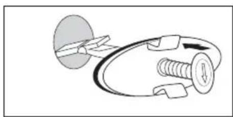
- With round overflows, press and hold the roll pin so that the locking lever can be flapped in such a way that it stands in extension with the roll pin (Fig. 1).

natural_image
Diagram of a mechanical device with rotating components and directional arrows indicating motion (no text or symbols)Fig. 1
- Guide it into the overflow. As soon as the locking lever hits against the rear wall, it opens itself out (Fig. 2).
natural_image
Diagram of a mechanical device with a circular component and threaded spring, showing motion direction (no text or symbols)Fig. 2
- Slowly release the roll pin and check to ensure that the overflow is completely closed. The edges of the overflow seal 10 must close as uniformly as possible around the overflow, otherwise residual soiling could be pressed out.

natural_image
Technical line drawing of a mechanical fastener assembly (no text or symbols)Fig. 3: Correctly inserted overflow seal 10
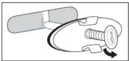
- For elongated overflows, press the roll pin and tip the locking lever so that it stands at right angles to the roll pin (Fig. 4).

natural_image
Diagram of a mechanical or electrical component with a lever and screw, no text or symbols presentFig. 4
- Guide it into the overflow. - Turn the roll pin through 90^ and slowly release it (Fig. 5).
natural_image
Diagram of a medical or surgical device with a curved tool and arrow indicating rotation (no text or symbols)Fig. 5
- Check to ensure that the overflow is completely closed. The edges of the overflow seal 10 must close as uniformly as possible around the overflow, otherwise residual soiling could be pressed out.
(i) Note:
The overflow seal ⑩ does not fit in all overflows. If the overflow seal ⑩ cannot close the overflow, use a cloth or something similar to seal it.

Warning in regard to property damage!
Use this appliance only on drains and pipeworks able to withstand pressure. Support poorly seated pipes against the floor! If you do not, the pressure surge could damage the pipe.
-
Close the plughole with a stopper and and pour some warm water into the bowl (up to about 7 cm above the plughole). The best possible pressure effect is achieved only when the blocked pipe is completely filled with water. Without water in the pipe the pressure effect is strongly reduced.
-
Build up a little pressure, in that you activate the pump ③ quickly about 3 - 4 times. If you pump too slowly, the air could escape from the appliance.
-
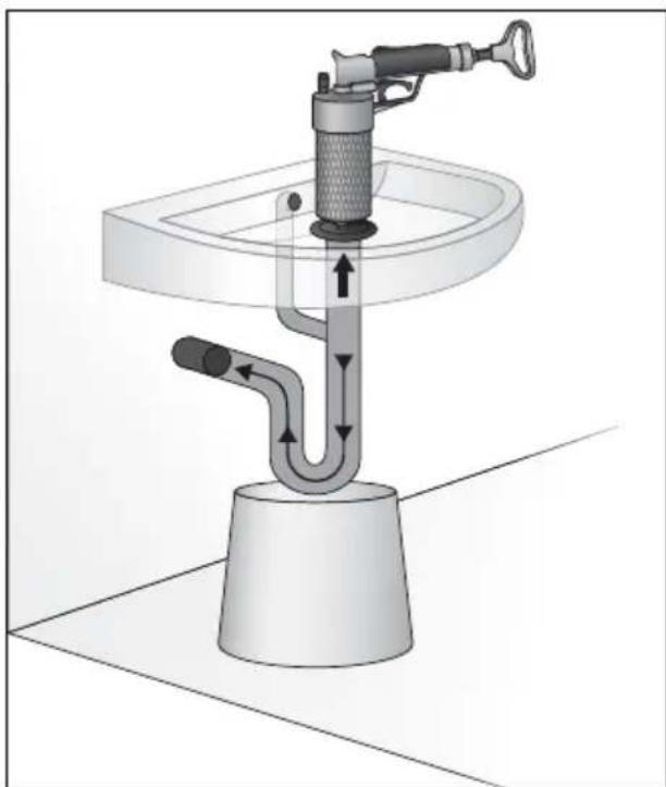
Remove the stopper and place the appliance, as shown in Fig. 6, on the plughole.
natural_image
Diagram of a shower pump system with tubing and valve, mounted on a sink (no text or labels)Fig. 6
-
Then release the pressure surge. When doing this, press the appliance firmly against the plug-hole.
-
If the blockage is not released, and you are sure that the pipe can withstand the pressure, increase the pressure for the next pressure surge.
-
Take the appliance out of the water and activate the pump ③ rapidly about 10 times.
-
Should you wish to release some pressure from the appliance, unscrew the air release valve ①. Afterwards, screw it back down firmly.
-
Place the appliance back onto the plughole and activate the pressure surge.
i Important:
Repeat these pressure surges only for as long as the water level is above the plughole. If necessary, refill with water.
- Repeat the pressure surge until the blockage is cleared.
(i) Note:
Should you not be able to build up pressure, check the air release valve ①. Ensure that it is firmly screwed onto the appliance.
Cleaning and care
- Clean the attachments 6/7/8/9 and the housing with a moist cloth. For stubborn soiling use a mild detergent on the cloth.
Attention! Appliance Damage!
Do not use aggressive, abrasive or chemical cleaning agents to clean the appliance or its attachments
6/7/8/9. These could damage the upper surfaces.
(i) Note:
The white powder on the pump ③ is not soiling. It is a talcum powder that was used in the factory for the first pump lubrication.
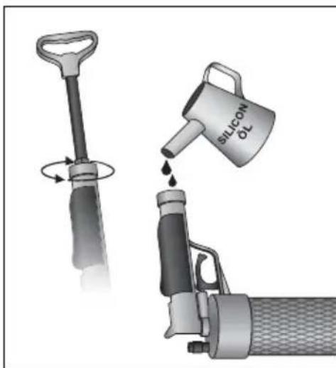
After frequent usage it could happen that the pump ③ may require lubrication:
- Unscrew the sealing cap ②.
- Insert a few drops of silicon oil into the handgrip. Other oils could damage the seals or the plastic.
natural_image
Illustration of a hand tool being inserted into a cylindrical device with a water droplet being poured into it (no text or symbols)Fig. 7
- Screw the sealing cap ② back on hand-tight.
Disposal
Dispose of the appliance in an environmentally-friendly manner. Observe the currently applicable regulations. In case of doubt, please contact your waste disposal centre.

Dispose of all packaging materials in an environmentally friendly manner.
Service
GB Service Great Britain
Tel.: 0871 5000 720 (£ 0.10/Min.)
E-Mail: kompernass@lidl.co.uk
IAN 73777
Importer
KOMPERNASS GMBH
BURGSTRASSE 21
44867 BOCHUM, GERMANY
www.kompernass.com
KOMPERNASS GMBH
Burgstraße 21
D-44867 Bochum
www.kompernass.com
- PRESSLUFT-ROHRREINIGER PPR 4 A1
- PRESSLUFT-ROHRREINIGER
- STURA TUBI AD ARIA COMPRESSA
- DÉBOUCHEUR DE TUYAUX
- PERSLUCHT ONTSTOPPER
- DE AT CH
- Milieurichtlijnen
- Drain Cleaner
- Congratulations!
- Intended Usage
- Safety instructions
- Risk of personal injury!
- Warning in regard to property damage!
- Items supplied
- Description of the appliance
- Technical Data
- Utilisation
- Note:
- i Important:
- Cleaning and care
- Attention! Appliance Damage!
- Disposal
- Service
- GB Service Great Britain
- Importer
Brand : POWERFIX
Model : PPR 4 A1
Category : Déboucheur de tuyaux