
BSK1065RVS - Range hood Pelgrim - Free user manual and instructions
Find the device manual for free BSK1065RVS Pelgrim in PDF.


| Brand | Pelgrim |
| Model | BSK1065RVS |
| Product type | Chimney hood |
| Overall dimensions | Width 60 cm, depth 50 cm, adjustable height |
| Weight | Approximately 12 kg |
| Power supply | 220-240 V, 50 Hz |
| Maximum power | 250 W (ventilation + lighting) |
| Number of speeds | 3 speeds + intensive position |
| Lighting | Integrated LED |
| Timer | Yes, 15 minutes |
| Clean air function | Yes, runs 10 min every hour |
| Filtration type | Washable metal grease filters + activated carbon filter (optional) |
| Extraction mode | External extraction (duct Ø 120/150 mm) or recirculation |
| Minimum distance from cooking surface | 65 cm (electric/ceramic/induction: 55 cm) |
| Filter saturation indicator | Yes (flashing of key A) |
| Cleaning of grease filters | At least once a month, in dishwasher or by hand |
| Carbon filter replacement | Every 4 months, not washable |
| Protection class | Class II (double insulation, without earth) |
| Spare parts available | Grease filters, carbon filters, LED bulbs |
| Warranty | 2 years (parts and labour) |
Frequently Asked Questions - BSK1065RVS Pelgrim
User questions about BSK1065RVS Pelgrim
0 question about this device. Answer the ones you know or ask your own.
Ask a new question about this device
Download the instructions for your Range hood in PDF format for free! Find your manual BSK1065RVS - Pelgrim and take your electronic device back in hand. On this page are published all the documents necessary for the use of your device. BSK1065RVS by Pelgrim.
USER MANUAL BSK1065RVS Pelgrim
natural_image
Exterior view of a stainless steel kitchen range hood (no text or symbols visible)BSK661
BSK765
BSK961
BSK965
BSK1065
Pelgrim
Instructions for use cooker hood
Pelgrim
NL

Bediening
natural_image
Illustration of a hand holding a rectangular object with a curved arrow inside, no text or symbols presentKoolstofffilter
natural_image
Mechanical assembly diagram showing a 90-degree angle with no visible text or symbolsMontage
Commande
natural_image
Illustration of a hand inserting a card into a rectangular device (no text or symbols visible)Filtres à charbon
natural_image
Mechanical component diagram showing a 90-degree angle with a directional arrow (no text or symbols on the component itself)Montage
natural_image
Diagram of a vertical structure with brick wall and support frame, showing airflow direction (no text or symbols)Bedienung
natural_image
Illustration of a hand inserting a device into an open notebook or folder (no text or symbols visible)Kohlefilter
natural_image
Mechanical component diagram showing a 90-degree angle with a highlighted section (no text or symbols present)natural_image
Diagram of a mechanical or electrical setup with a box, wires, and three labeled components (no text or symbols present)Montage
natural_image
Symbol of a trash bin with crossed lines indicating no waste or discharge (no text or numbers present)| Description | 4 | ||
| Introduction | 4 | ||
| Safety | |||
| Precautions you must take 5 | |||
| Extraction systems | 5 | ||
| Use | |||
| Controls | 6 | ||
| Maintenance | |||
| Cleaning | 8 | ||
| Removing the grease filters 9 | |||
| Replacing the carbon filter 9 | |||
| Lighting | 9 | ||
| Installation | |||
| General | 10 | ||
| Electrical connection | |||
| Mounting the canopy hood 12 | |||
| Appendice | |||
| Disposal of appliance and packaging 13 | |||
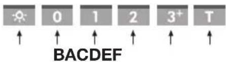
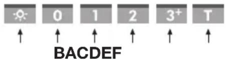
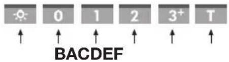
Description
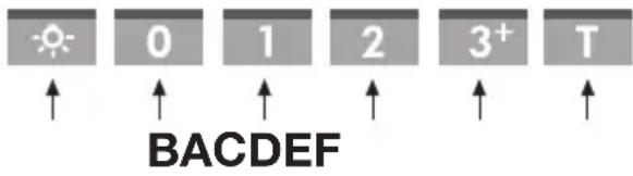
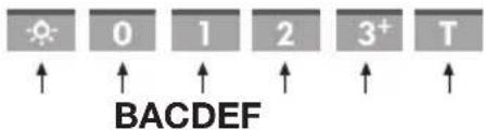
A Lighting
B Switch off
C Fan position 1
D Fan position 2
E Fan position 3/ Intensive setting
F Timer
Introduction
This user manual gives you a quick overview of all the possibilities offered by the appliance. You will find information on safety measures and maintaining the appliance.

Please retain this user manual and the installation guide. They may be of use to future users of the appliance.
Declaration of conformity
We declare that our products meet the applicable European Directives, Decisions and Regulations and the requirements listed in the standards referenced.

Please read the separate safety instructions prior to use.
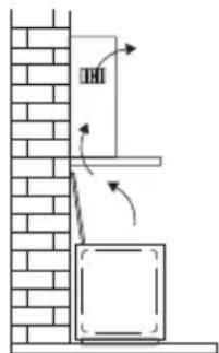
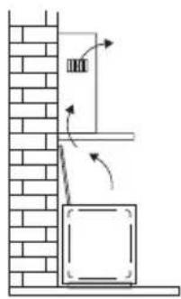
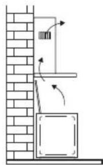
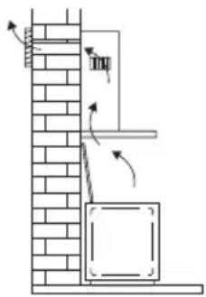
Extraction systems
Depending on the type, the cooker hoods can be connected in one of two ways:
- To a duct. To a duct, the cooking vapours extracted by suction are carried outside, once the grease particles have been filtered. This is the best method.
- Recirculation hood. As a recirculation hood, the grease particles and the smell in the extracted vapours are filtered. The air that has been sucked in is not carried outside but recirculates in the kitchen. In this case you must have a carbon filter fitted.
Attention! The carbon filter needs to be ordered separately.
natural_image
Diagram of a brick wall with directional arrows indicating movement or force, showing structural components and airflow (no text or symbols)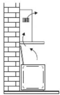

Controls
Switching fan on and off
Press the speed button C, D or E
The extractor hood switches on in the corresponding position.
Press the off button B.
The fan will switch off.
Intensive setting
You can temporarily switch the extractor hood to the highest setting – in order, for example, to remove the odour quickly if something has burned.
Press for 2 seconds switch E to switch to the intensive setting.
The extractor hood switches to its highest setting for 10 minutes, and then switches back to the original setting.
Switching lighting on and off
Press the lighting button A.
The lighting switches on.
Press the lighting button A again.
The lighting switches off.
Timer
(In the off position) press and hold the F button for 2 seconds.
This activates the Clean air function.
The cooker hood is switched on for 10 minutes every hour. When the extractor is working, the C and F buttons start flashing. After 10 minutes the extractor switches off and the F button remains on.
Changing the filters
If button A is flashing slowly, then the filters need to be cleaned. If button A is flashing rapidly, then the carbon filters need to be changed.
Reset the controls after changing or cleaning the filters.
Press and hold light button A for 5 seconds.
Button A will stop flashing.
Cleaning

Attention! Before performing any maintenance operation, isolate the hood from the electrical supply by switching off at the connector and removing the connector fuse. Or if the appliance has been connected through a plug and socket, then the plug must be removed from the socket.
The cooker hood should be cleaned regularly (at least with the same frequency with which you carry out maintenance of the fat filters) internally and externally. Do not use abrasive products. Do not use alcohol!
Attention! Failure to carry out the basic cleaning recommendations of the cooker hood and replacement of the filters may cause fire risks. Therefore, we recommend oserving these instructions.
The manufacturer declines all responsibility for any damage to the motor or any fire damage linked to inappropriate maintenance or failure to observe the above safety recommendations.
Cooker hood
Clean the cooker hood with soapy water and a soft cloth. Then wipe with clean water to rinse. Do not use aggressive cleaning agents such as soda. The cooker hood paintwork will stay looking nice if you wax it occasionally.

Stainless steel canopy hoods
Do not use any sort of scourer. Treat with a stainless steel care product and polish with the structure of the stainless steel.
Metal grease filters
These must be cleaned once a month (or when the filter saturation indication system – if envisaged on the model in possession – indicates this necessity) using non aggressive detergents, either by hand or in the dishwasher, which must be set to a low temperature and a short cycle. The openings must be placed downwards to let the water run out of the filters. The cleaning agents will make the aluminium filter turn dull, this is normal.
Grease filters
natural_image
Illustration of a hand holding a clipboard with a curved arrow indicating motion (no text or symbols)Removing the grease filters
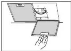
Switch off the electricity! Remove the plug from the socket or switch the electricity off at the mains. Pull the grease filter towards you and tilt it downwards at the front.
natural_image
Mechanical component diagram showing a 90-degree angle with directional arrow (no text or symbols)Replacing the carbon filter
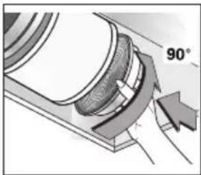
The carbon filter must always be used if the cooker hood is not ducted.
- Remove the grease filters.
- Attach the carbon filters to the motor.
- Replace the filter grids in the extractor hood.
Note:
- Saturation of the activated charcoal will eventually occur after more or less prolonged use, depending on the type of cooking and how frequently the grease filter is cleaned.
- In all cases it is necessary to replace the cartridge at least every four months.
- DO NOT wash or reuse the carbon filter. Saturated carbon is not environmentally friendly, change the filter regularly.
Lighting

Faulty LEDs must be replaced by a professional installer.
General
This appliance should be connected to the power supply by a recognized fitter who is familiar with, and works according to the correct safety regulations. This appliance meets the European requirements.
Important that you know:
- The minimum distance between the supporting surface for the cooking vessels on the gashob and the lowest part of the range hood must be not less than 65 cm. For use with an electric, ceramic or induction hob, this distance must be at least 55 cm.
- If the cooker hood is to be fitted to an existing duct no other appliances, such as a geyser or heater, may be connected to that same duct.
- Consider local regulations with respect to the ventilation of gas appliances.
- The shorter the duct, and the fewer the bends in it, the better the cooker hood will work.
- Before you start drilling check that there are no installation cables present.
- The connecting pipe for the cooker hood has a diameter of 120 or 150 mm. It is best also to use a flue pipe of the same diameter.
- The installation material supplied with this range hood is designed for fixing to reinforced concrete or masonry walls. For some types of walls you may need special plugs and screws.
Connection
Electric connection
The appliance has been manufactured as a class II, therefore no earth cable is necessary.
Make sure the supply voltage ratings correspond with those stated on the appliance data plate. The connection to the mains is carried out as follows:
BROWN = phase L
BLUE = phase N
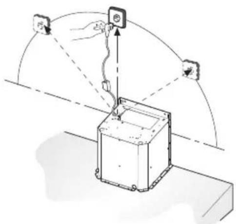
This canopy hood has been provided with a power plug. When installing the hood, make sure that this plug remains accessible. We recommend installing the wall socket out of view, behind the chimney cover.

Attention:
If you want to make a fixed connection, ensure that a multi-pole switch with a distance between contacts of 3 mm is installed in the supply cable.
max 90 cm
Mounting
- Mount the hood on the wall using the plugs and screws provided bracket (A). Check size specifications.
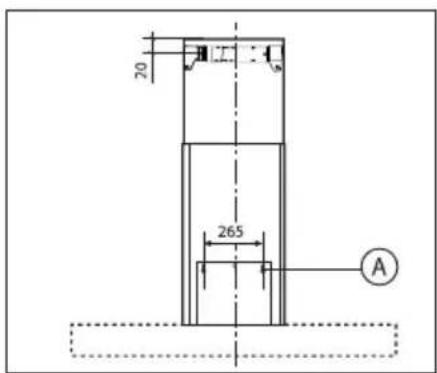
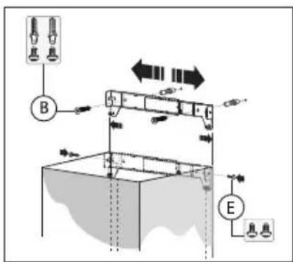
- Adjust the width of the brackets to the width of the upper chimney. Next, mount the bracket on the wall using the plugs and the screws (B). Take into account the distance between the brackets bracket and the ceiling (Check size specifications).
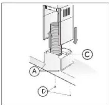
• Install the vent duct on the flange (C) and then onto the connecting surface of the exhaust grid.
• Put the plug in the wall socket.
- Slide the upper chimney into the lower chimney.
- Attach the lower chimney to the hood using the screws provided (D).
- Slide the upper chimney around the bracket and attach with the screws provided (E).
Disposal
Disposal of appliance and packaging
By ensuring this product is disposed of correctly, you will help prevent potential negative consequences for the environment and human health, which could otherwise be caused by inappropriate waste handling of this product. The local authorities can provide you with the relevant information.
The packaging of this appliance is recyclable. It could have been made from:
- cardboard;
- polythene foil (PE);
• CFK-free polystyrene (PS-hard foam).
You need to dispose of these materials responsibly in accordance with official regulations.

natural_image
Symbol of a trash bin with crossed lines indicating no waste or discharge (no text or numbers present)To draw attention to the fact that the segregated processing of electric household appliances is compulsory, this appliance carries the symbol of a crossed-out dustbin. This means that at the end of its working life, you may not dispose of the appliance as household refuse. Instead, you should hand it in at a special refuse collection centre run by the local authority or at a dealer's providing this service.
Segregated processing of household appliances avoids any negative effects on the environment and public health that might otherwise occur.
It enables the recovery of the materials used in the production of this appliance, thus realising considerable savings in terms of raw materials and energy.



- Pelgrim
- Bediening
- Koolstofffilter
- Montage
- Commande
- Filtres à charbon
- Bedienung
- Kohlefilter
- Description
- Introduction
- Declaration of conformity
- Please read the separate safety instructions prior to use.
- Extraction systems
- Depending on the type, the cooker hoods can be connected in one of two ways:
- Controls
- Switching fan on and off
- Intensive setting
- Switching lighting on and off
- Timer
- Changing the filters
- Cleaning
- Cooker hood
- Stainless steel canopy hoods
- Metal grease filters
- Grease filters
- Removing the grease filters
- Replacing the carbon filter
- Note:
- Lighting
- General
- Important that you know:
- Connection
- Electric connection
- Attention:
- Mounting
- Disposal
- Disposal of appliance and packaging
Brand : Pelgrim
Model : BSK1065RVS
Category : Range hood