
10033709 - Range hood Klarstein - Free user manual and instructions
Find the device manual for free 10033709 Klarstein in PDF.


User questions about 10033709 Klarstein
0 question about this device. Answer the ones you know or ask your own.
Ask a new question about this device
Download the instructions for your Range hood in PDF format for free! Find your manual 10033709 - Klarstein and take your electronic device back in hand. On this page are published all the documents necessary for the use of your device. 10033709 by Klarstein.
USER MANUAL 10033709 Klarstein
KLARSTEIN NIEIJSRYATK TEIN NIEIJSRYATK KLAR KLARSTEIN NIEIJSRYATK TEIN NIEIJSRYATK KLAR KLARSTEIN NIEIJSRYATK TEIN NIEIJSRYATK KLAR KLARSTEIN NIEIJSRYATK
KLARSTEIN
Dunstabzugshaube
Cooker Hood
Campana extractora
Hotte aspirante
Cappa aspirante

bar
| Category | Value | |---|---| | Bar 1 | 100 | | Bar 2 | 100 |INSTALLATIONSZUBEHÖR
text_image
20 12 11 21 13 10natural_image
Technical line drawing of a conical structure with a vertical dimension labeled 313 (no text or symbols present)Maße
text_image
170 172 226 229 A B 301 40 500 596natural_image
Technical line drawings of a mechanical bracket with multiple bolt holes and mounting points (no text or symbols)| Option Abzug X | |
| 1 400+0 / | |
| 2 400+300 390-620 | |
| 3 400+390 390-710 |
Markierungslinien
natural_image
Technical line drawing of a mechanical assembly with a magnified inset showing a component detail (no text or symbols)BEDIENFELD UND TASTENFUNKTIONEN
Bedienfeld
text_image
Five circular icons with Chinese characters and symbols: power plug, butterfly, bird, bird, sunTastenfunktionen
natural_image
Illustration of a hand holding a smartphone with a finger pointing at it, showing a download arrow (no text or symbols present)Aktivkohlefilter (Umluftversion)
natural_image
Line drawings of three different household appliances: a front panel, hands holding a tool, and a wall-mounted appliance (no text or symbols present)Ersatzlicht
natural_image
Symbol of a trash bin crossed with a diagonal line, representing no waste or discharge (no text or labels)supplier's trade mark: Klarstein
supplier's model identifier: 1003 /100337103709
| Description | Symbol | Value | Unit |
| Annual Energy Consumption | AEC hood | 90,6 | kWh/a |
| Energy Efficiency class | C | ||
| Fluid Dynamic Efficiency | FDE hood | 19,6 | |
| Fluid Dynamic Efficiency class | C | ||
| Lighting Efficiency | LE hood | 4 | lx/W |
| Lighting Efficiency class | A | ||
| Grease Filtering Efficiency | GFE hood | 7 , | % |
| Grease Filtering Efficiency class | C | ||
| air flow at minimum and maximum speed in normal use, intensive or boost excluded | 644, | m^3/h | |
| air flow at intensive or boost setting | - | m^3/h | |
| airborne acoustical A-weighted sound power emissions at minimum and maximum speed available in normal use | 67 | dB | |
| airborne acoustical A-weighted sound power emissions at intensive or boost setting | - | dB | |
| power consumption in off mode | P_o | 0 | W |
| power consumption in standby mode | P_s | 0,41 | W |
Angaben / Information 66/2014
| Symbol | Value | Unit | |
| Model identification | 10033709/0033710 | ||
| Annual Energy Consumption | AEChood | 90,6 | kWh/a |
| Time increase factor | f | 1,3 | |
| Fluid Dynamic Efficiency | FDE hood | 19,6 | |
| Energy Efficiency Index | EEIhood | 75,8 | |
| Measured air flow rate at best efficiency point | Q BEP | 357,0 | m^3/h |
| Measured air pressure at best efficiency point | P BEP | 368 | Pa |
| Maximum air flow | Q MAX | 644,5 | m^3/h |
| Measured electric power input at best efficiency point | W BEP | 186,4 | W |
| Nominal power of the lighting system | WL | 1,5x2,0 | W |
| Average illumination of the lighting system on the cooking surface | E middle | 163 | Lux |
| Measured power consumption in standby mode | Ps | 0,41 | W |
| Measured power consumption off mode | Po | 0 | W |
| Sound power level | LWA | 67 | dB |
Dear Customer,
Congratulations on purchasing this equipment. Please read this manual carefully and take care of the following hints to avoid damages. Any failure caused by ignoring the mentioned items and cautions mentioned in the instruction manual are not covered by our warranty and any liability.
CONTENT
Safety Instructions 26
Product Description 29
Installation Components 30
Dimensions 31
Installation 33
Chimney Assembly 36
Control Panel and Key Functions 37
Care and Cleaning 38
Troubleshooting 40
Hints on Disposal 42
TECHNICAL DATA
| Item number 1003370 | 9, 10033710 |
| Power supply 220-240 V ~ 50 Hz |
DECLARATION OF CONFORMITY

text_image
C€Producer:
Chal-Tec GmbH, Wallstraße 16, 10179 Berlin, Germany.
This product is conform to the following European Directives:
2014/30/EU (EMC)
2014/35/EU (LVD)
2011/65/EU (RoHS)
2009/125/EC (ErP)
SAFETY INSTRUCTIONS
Read the user manual carefully before installing and operating the unit, and keep it for future reference.
Note: The instructions for Use apply to several versions of this appliance. Accordingly, you may find descriptions of individual features that do not apply to your specific appliance.
Installation
- The manufacturer will not be held liable for any damages resulting from incorrect or improper installation.
- The minimum distance between the supporting surface for the cooking vessels on the hob and the lowest part of the range hood. (When the range hood is located above a gas appliance, this distance shall be at least 65 cm. If the instructions for installation for the gas hob specify a greater distance, this has to be taken into account. The distance of 65 cm can be reduced for:non-combustible parts of range hoods, and parts operating at safety extra low voltage, Provided these parts do not give access to live parts if deformed.
- Check that the mains voltage corresponds to that indicated on the rating plate fixed to the hood.
- For Class I appliances, check that the domestic power supply guarantees adequate earthing.
- Connect the extractor to the exhaust flue through a pipe of minimum diameter 120mm. The route of the flue must be as short as possible.
- The air must not be discharged into a flue that is used for exhausting fumes from appliances burning gas or other fuels.
- If the extractor is used in conjunction with non-electrical appliances (e.g. gas burning appliances), a sufficient degree of aeration must be guaranteed in the room in order to prevent the backflow of exhaust gas. The kitchen must have an opening communicating directly with the open air in order to guarantee the entry of clean air. When the cooker hood is used in conjunction with appliances supplied with energy other than electric, the negative pressure in the room must not exceed 0,04 mbar to prevent fumes being drawn back into the room by the cooker hood.
- If the supply cord is damaged, it must be replaced by the manufacturer, its service agent or similarly qualified persons in order to avoid a hazard.
• Regulations concerning the discharge of air have to be fulfilled.
Use
- The cooker hood is only for home use, not suitable for barbecue, roast shop and other commercial purposes.
- Never use the hood for purposes other than for which it has been designed.
- Never leave high naked flames under the hood when it is in operation.
- Adjust the flame intensity to direct it onto the bottom of the pan only, making sure that it does not engulf the sides.
- Deep fat fryers must be continuously monitored during use: overheated oil can burst into flames.
- Do not flame under the range hood; risk of fire.
- This appliance can be used by children aged from 8 years and above and persons with reduced physical, sensory or mental capabilities or lack of experience and knowledge if they have been given supervision or instruction concerning use of the appliance in a safe way and understand the hazards involved.
• Children should be supervised to ensure that they do not play with the appliance. - Cleaning and user maintenance shall not be made by children without supervision.
CAUTION
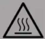
Risk of burns! Accessible parts may become hot when used with cooking appliances. Take care that you do not burn yourself.
Maintenance
- The cooker hood and its filter should be cleaned regularly according to the instruction.
- Switch off or unplug the appliance from the mains supply before carrying out any maintenance work.
- Clean and/or replace the Filters after the specified period (Fire hazard).
- Clean the hood using a damp cloth and a neutral liquid detergent.
• The appliance uses 4 hob elements at most.
Important notes about the extraction mode

Risk of poisoning from exhaust gases sucked back. Never operate the device in extraction mode simultaneously with an open flue appliance when there is not adequate airflow guaranteed.
Open fl ue combustion equipment (for example, gas, oil, wood or coal-fi red heaters, tankless water heaters, water heaters) pulls combustion air from the room and runs it through an exhaust pipe or chimney to the outside. In the extraction mode, indoor air is removed from the kitchen and the adjacent rooms - without sufficient air intake this creates a vacuum. Toxic gases from the chimney or extraction fl ue can thereby be sucked back into the living spaces.
- Always ensure that a sufficient supply of fresh air is guaranteed and that the air can circulate.
- An air supply / extractor box alone does not ensure compliance with the limit value.
Safe operation is only possible when the negative pressure in the room where the appliance is located does not exceed 4 Pa (0.04 mbar). This can be achieved when the air required for combustion can flow through openings that are not closable, for example in doors, windows, in conjunction with an air supply / extractor box or through other technical measures. In any case, consult a qualified chimney sweep who can assess the entire ventilation of your house and propose appropriate measures for adequate ventilation.
If the hood is used exclusively in the recirculation mode, unrestricted operation is possible.

Fire hazard from flying sparks. Only install equipment on a fi replace for solid fuels (for example, wood or coal), if a closed, non-removable cover is available.
PRODUCT DESCRIPTION
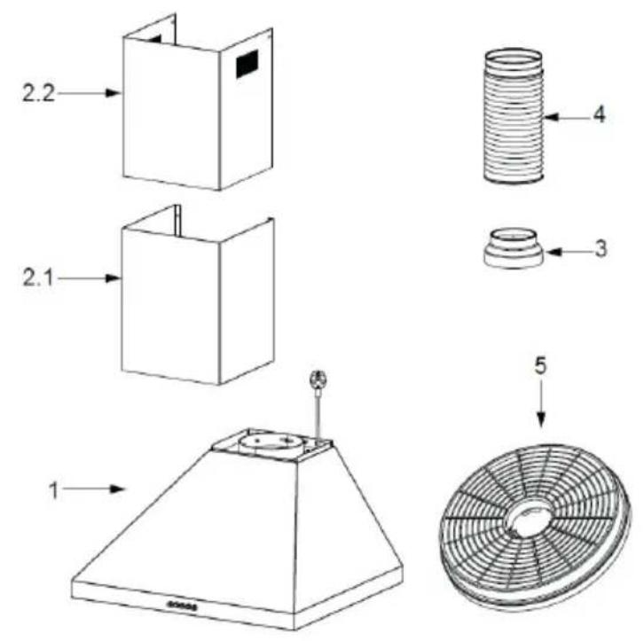
| Ref. Qty. | Product Components |
| 1 1 Hood | Body, complete with:Controls, Light, Blower, Filter. |
| 2.1 1 Lower Decorative Chimney | |
| 2.2 1 Upper Decorative Chimney (optional) | |
| 3 1 Flange (optional) | |
| 4 1 Exhaust Pipe | |
| 5 2 The Activated Charcoal filter (optional) | |
Note: The optional accessory is not included in the delivery.
INSTALLATION COMPONENTS
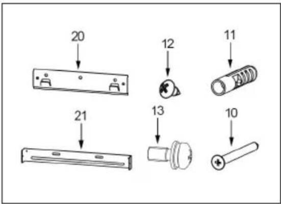
text_image
20 12 11 21 13 10Standard Installation Components
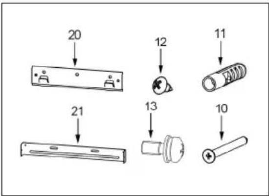
| Ref. Qty. | Component | |
| 10 5 Screws | 5 × 50 | |
| 11 5 Wall Plugs | ||
| 12 4 Screws | 4,2 × 9,5 | |
| 13 2 Screws | 5 × 12 | |
| 20 1 Hood fixing bracket | ||
| 21 1 Chimney fixing bracket (optional) | ||
Optional Installation Components (not included in the delivery)
| Ref. Qty. | Component | |
| 10 7 Screws | 5 x 50 | |
| 11 7 Wall Plugs | ||
| 12 6 Screws | 4,2 x 9,5 | |
| 20 1 Hood fixing bracket | ||
| 21 1 Chimney fixing bracket (optional) | ||
Note: If choose these installation components, refer to „Solution 2“ in the installation diagram.
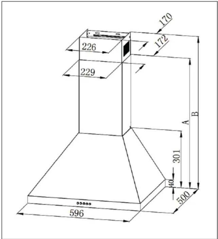
DIMENSIONS
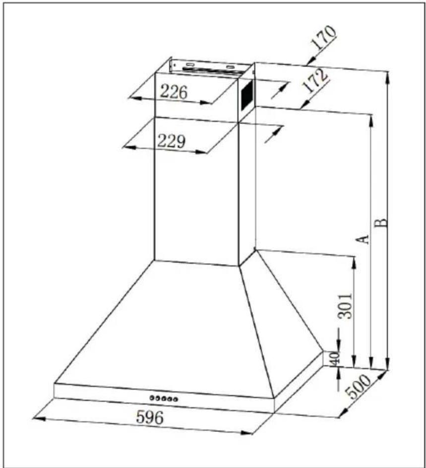
Note: The specified values are [mm].
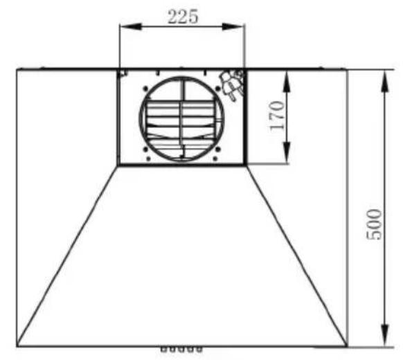
text_image
225 170 500 600mm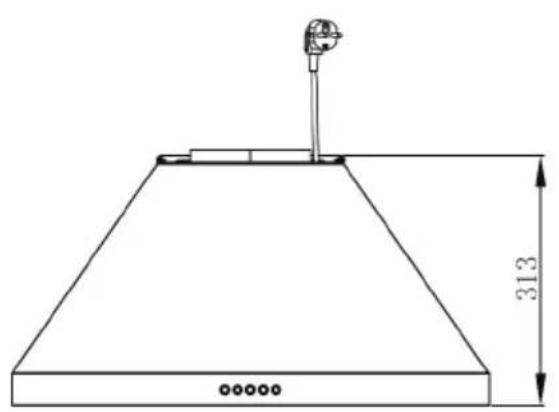
natural_image
Technical line drawing of a conical structure with a vertical dimension labeled 313 (no text or symbols beyond the dimension)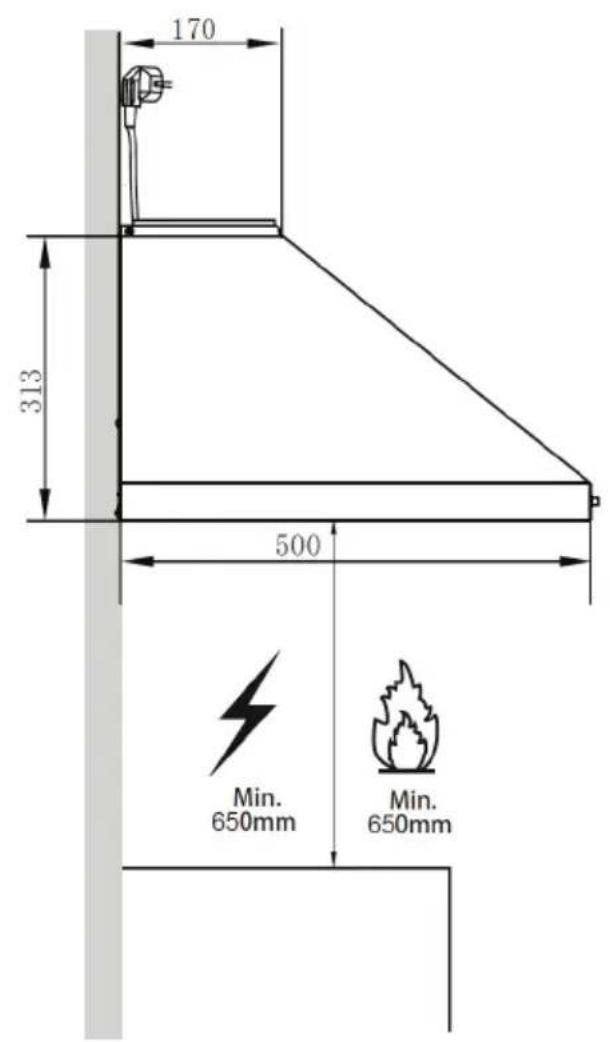
text_image
170 313 500 Min. 650mm Min. 650mmMaße
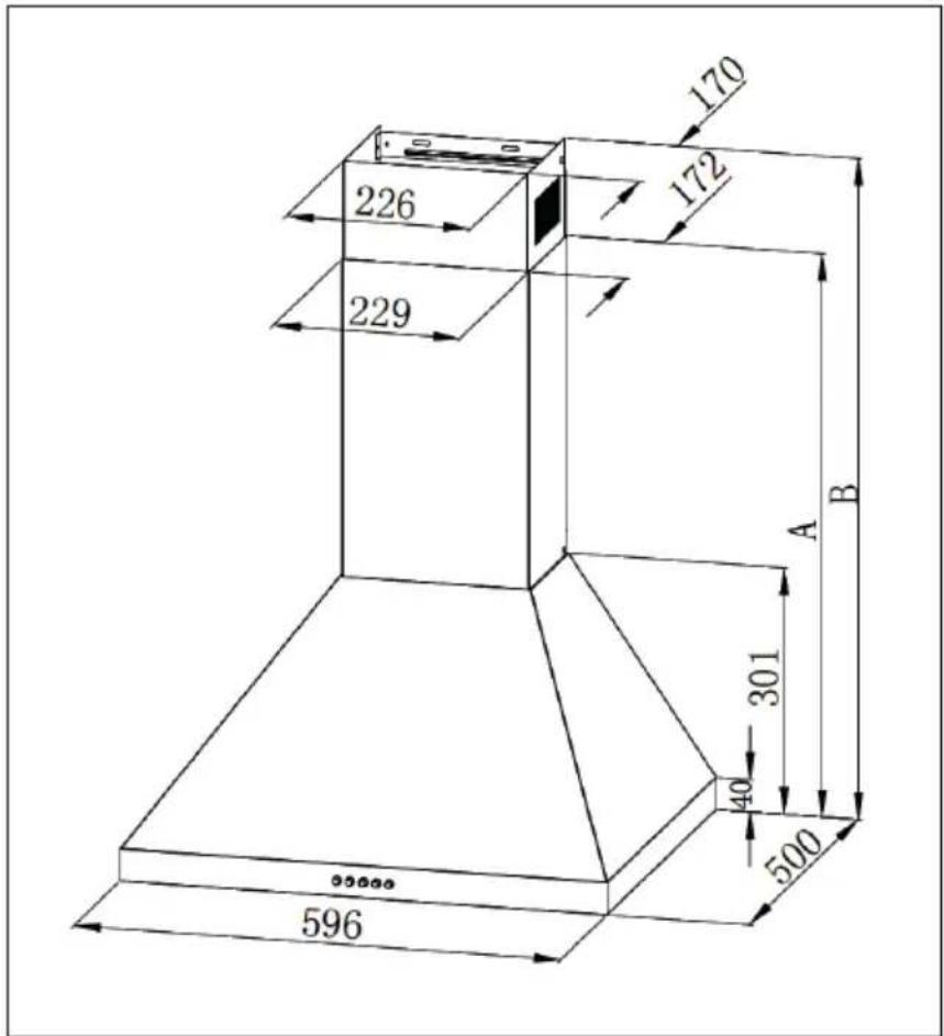
text_image
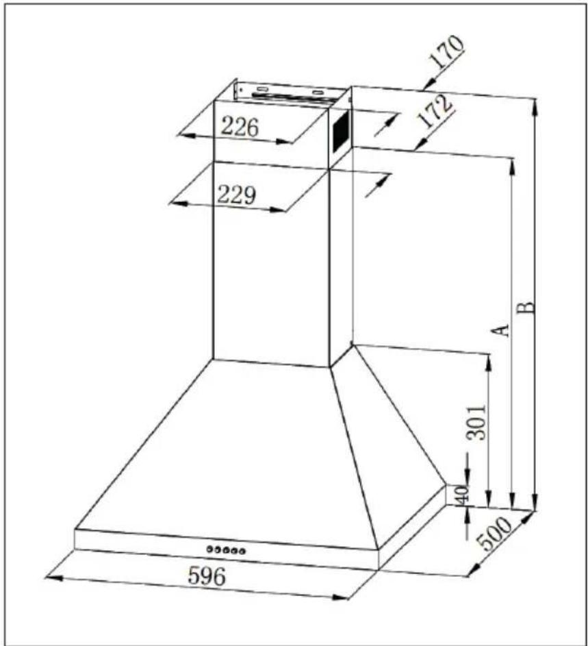
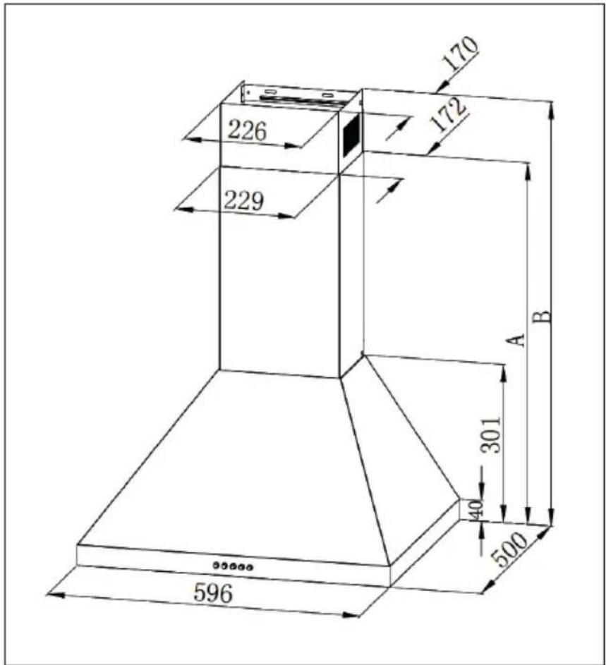
170 172 226 229 A B 301 40 500 596| Option Chimney A B | |||
| 1 400+0 690 / | |||
| 2 400+300 690 730-970 | |||
| 3 400+390 690 730-1060 | |||
| Note: The specified values are [mm]. | |||
INSTALLATION
Note: The specified values are [mm].
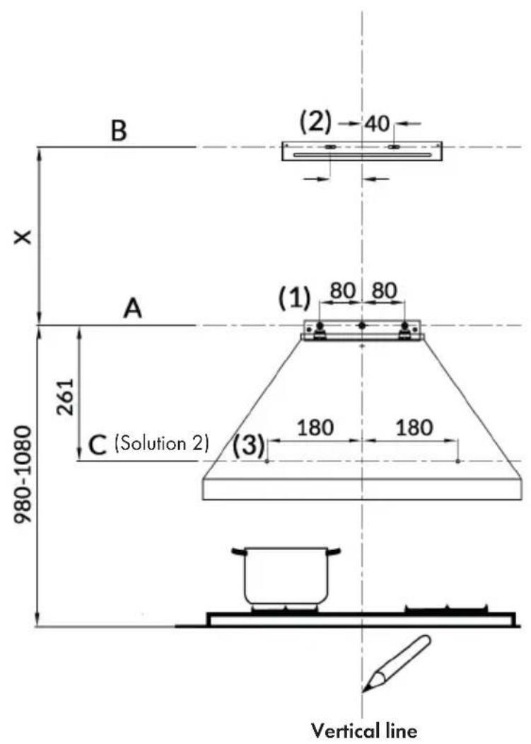
text_image
B (2) 40 X A (1) 80 80 261 C (Solution 2) 980-1080 (3) 180 180 Vertical line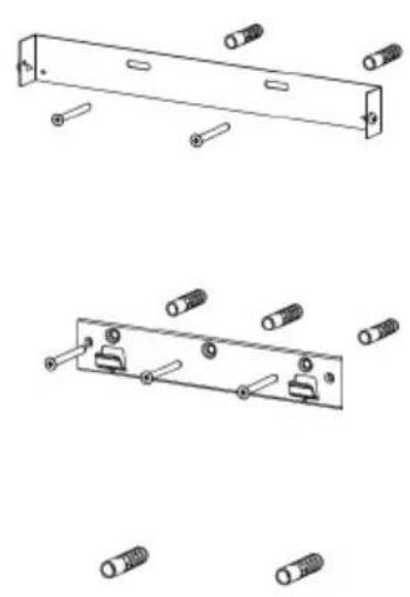
natural_image
Technical line drawings of a mechanical bracket with multiple bolt holes and mounting points (no text or symbols)| Option Chimney X | |
| 1 400+0 / | |
| 2 400+300 390-620 | |
| 3 400+390 390-710 |
Wall Drilling and Bracket Fixing
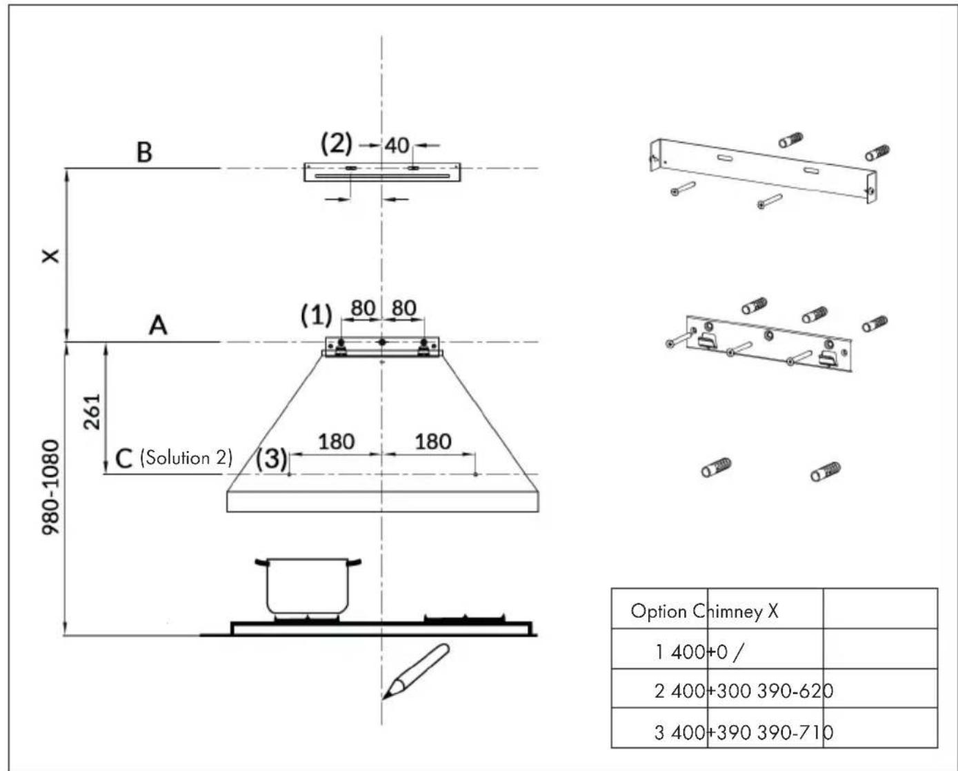
As a first step, proceed with the following drawings:
- A vertical line up to the ceiling or up to the upper limit, at the center of the area in which the hood is to be fitted.
(A) A horizontal line A at 980 - 1080 mm above the cooker top.
(B) A horizontal line B at a X mm above the horizontal line A.
(C) A horizontal line C at a 261 mm below the horizontal line A (only valid for „Solution 2“).
Mark Points
Note: The specified values are [mm].
text_image
B (2) 40 X A (1) 80 80 261 C (Solution 2) (3) 180 180 980-1080 Option Chimney X 1 400+0 / 2 400+300 390-620 3 400+390 390-710(1) Mark a point (1) on the horizontal line A, 80 mm to the right of the vertical reference line. Repeat this operation on the other side and on the vertical reference line, checking that the three marks are leveled.
(2) Mark a point (2) on the horizontal line B, 40 mm to the right of the vertical reference line. Repeat this operation on the other side, checking that the two marks are leveled.
(3) Mark a point (3) on the horizontal line C, 180 mm to the right of the vertical reference line (Solution 2). Repeat this operation on the other side, checking that the two marks are leveled.
Fix the brackets (optional)
- Drill at the marked points (1), (2), (3) (Solution 2), using a 10 mm drill bit.
- Insert the Wall Plugs into the holes (1), (2), (3) (Solution2).
• Fix the hood fixing bracket with 3 screws (5 x 50) at the horizontal line A.
• Fix the Chimney fixing bracket with 2 screws (5 x 50) at the horizontal line B.
Hook the hood body
- Hook the hood body to the bracket.
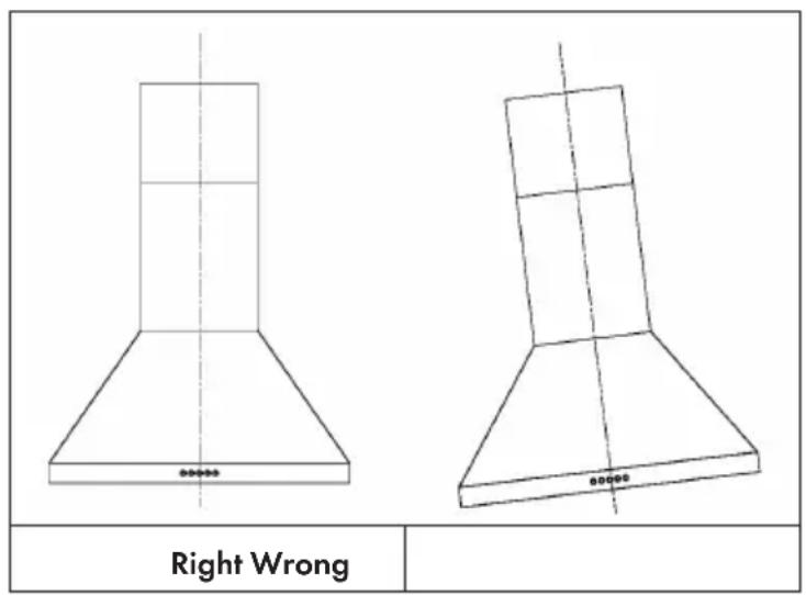
• Level the hood body itself. - Lock screws (M5 x 12) on the hood fixing bracket to prevent the hood body from accidentally sliding off. Remove the filter from the inside of the hood body, fix the screws to Wall Plugs at the points (3) (Solution 2).
text_image
Right WrongConnections to ducted version air exhaust system
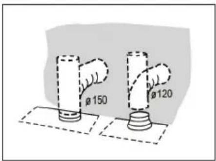
When installing the ducted version, connect the hood to the chimney using either a flexible or rigid pipe 150 mm or 120 mm, the choice of which is left to the installer.
- If to install a 120 mm air exhaust connection, insert the reducer flange on the hood body outlet.
• Fix the pipe in position using sufficient pipe clamps (not supplied). - Remove possible charcoal filters.
text_image
Ø 150 Ø 120CHIMNEY ASSEMBLY
The chimney can only be installed with exhausting hood.
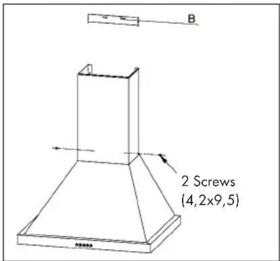
Lower Decorative Chimney
- Fix the Lower Decorative Chimney to the hood body with 2 screws (4.2x9.5) supplied with the hood.
text_image
2 Screws (4,2x9,5)Upper Decorative Chimney
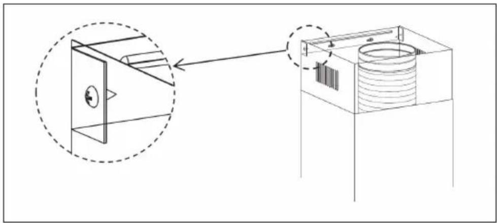
- Fix the upper chimney onto the bracket with 2 screws 12 (4.2x 9.5) supplied with the hood.
natural_image
Technical diagram showing a mechanical assembly with a dashed circular inset view of a component (no text or symbols present)CONTROL PANEL AND KEY FUNCTIONS
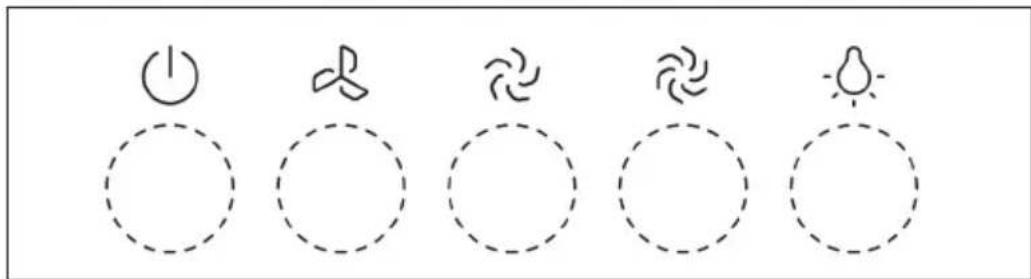
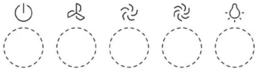
Control Panel
text_image
Five circular icons with Chinese characters and symbols: power plug, butterfly, bird, bird, sunKey Functions
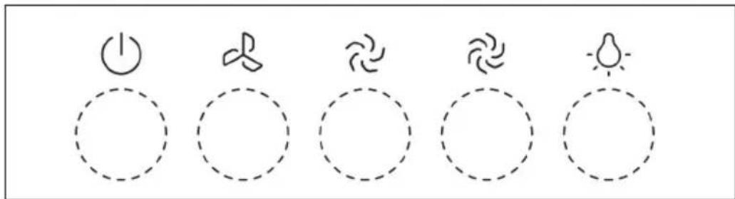
 | Off motor switch: press on this switch to stop the motor operation. |
 | Speed switch: press on this switch, the motor runs at low speed. |
 | Speed switch: press on this switch, the motor runs at medium speed. |
 | Speed switch: press on this switch, the motor runs at high speed. |
 | On/Off lighting switch: press on this switch to turn on the lights, and press again to turn them off. |
CARE AND CLEANING
Grease Filters
- The filters must be cleaned every 2 months of operation, or more frequently for particularly heavy usage, and can be washed in a dishwasher.
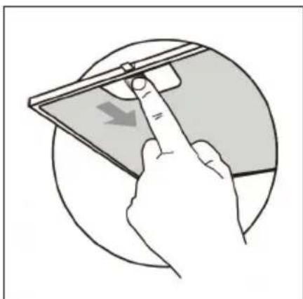
- Remove the filters one by one pushing them towards the back side of the hood unit and simultaneously pulling downwards.
- Any kind of bending of the filters has to be avoided when washing them. Before fitting them again into the hood make sure that they are completely dry. (The color of the filter surface may change throughout the time but this has no influence to the filter efficiency).
- When fitting the filters into the hood pay attention that they are mounted in correct position the handle facing outwards.
natural_image
Illustration of a hand holding a smartphone with a finger pointing at it, showing a download arrow (no text or symbols present)Activated Charcoal Filter (recirculation version)
These filters are not washable and cannot be regenerated, and must be replaced approximately every 4 months of operation, or more frequently with heavy usage.
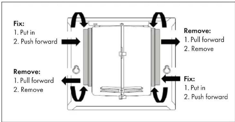
Replacing the activated charcoal filter:
1 Remove the metal grease filters
2 Remove the saturated activated charcoal filter.
3 Fit the new filters.
4 Replace the metal grease filters.
flowchart
graph TD
    A["Fix"] --> B["1. Put in"]
    A --> C["2. Push forward"]
    D["Remove"] --> E["1. Pull forward"]
    D --> F["2. Remove"]
    G["Fix"] --> H["1. Put in"]
    G --> I["2. Push forward"]
    J["Remove"] --> K["1. Pull forward"]
    J --> L["2. Remove"]
Light Replacement
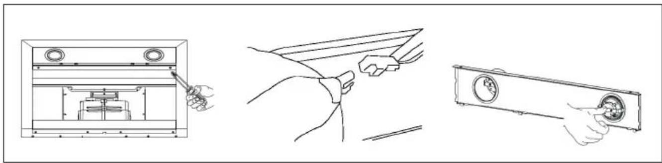
1 Remove the grease filter and carefully remove the 2 screws from the front plate (a cross headed screwdriver will be needed to remove the screws).
2 Disconnect the terminal of LED light.
3 Press LED light on the back of the front plate, take the LED light out.
4 Replace the lamp(commercially available LED lamp (max.1.5W).
natural_image
Line drawings of three different household appliances: a front panel, hands holding a tool, and a wall-mounted appliance (no text or symbols present)Replacement Light
| ∅ Max Power Voltage Picture | ILCOS D code | |||
| 70 mm 1,5 W DC 12 V | 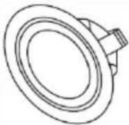 | DSR-1.5-S-70 | ||
Reinstall LED Light Module
1 Press LED light on the front of front plate, install the LED light on the front plate.
2 Connect the terminal of LED light and light leads.
3 Carefully fasten the 2 screws on the front plate, reinstall the grease filter.
TROUBLESHOOTING
| Problem Cause Solution | ||
| Light on, but motor does not work | The blades are blocked. Check the blades. | |
| The capacitor is damaged. Replace capacitor. | ||
| The motor is damaged. Replace motor. | ||
| The internal wiring f motor is cut off/disconnected.An unpleasant smell may be produced. | ||
| Both light and motor do not work | Apart from the above mentioned, check the following: | |
| Light damaged. Replace lights. | ||
| Power cord loose. Connect the wires as the electric diagram. | ||
| Oil leakage Outlet and the air ventilation entrance are not tightly sealed. | Take down the outlet and seal with glue. | |
| Vibration The blade, if damaged, can cause vibrating. | Replace the blade. | |
| The motor is not tightly fastened. | ||
| The cooker hood is not tightly fixed. | ||
| Insufficient suction The distance between the cooker hood and the cooker top is too large. | Readjust the distance. | |
| Too much ventilation from open doors or windows. | ||
| The machine inclines The fixing screws are not tight enough. | Tighten the fixing screw and make it horizontal. | |
| The hanging screws are not tight enough | ||
HINTS ON DISPOSAL
natural_image
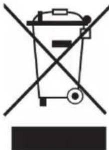
Symbol of a trash bin crossed with a diagonal line, representing no waste or discharge (no text or labels)According to the European waste regulation 2012/19/EU this symbol on the product or on its packaging indicates that this product may not be treated as household waste. Instead it should be taken to the appropriate collection point for the recycling of electrical and electronic equipment. By ensuring this product is disposed of correctly, you will help prevent potential negative consequences for the environment and human health, which could otherwise be caused by inappropriate waste handling of this product. For more detailed information about recycling of this product, please contact your local council or your household waste disposal service.
Estimado cliente:
natural_image
Technical line drawing of a conical structure with a vertical dimension labeled 313 (no text or symbols beyond the dimension)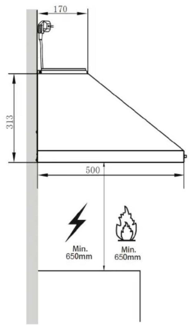
text_image
170 313 500 Min. 650mm Min. 650mmDimensiones
text_image
170 172 226 229 A B 301 40 500 596natural_image
Technical line drawings of a mechanical bracket with multiple bolt holes and mounting points (no text or symbols)| Opción Tiro X | |
| 1 400+0 / | |
| 2 400+300 390-620 | |
| 3 400+390 390-710 |
Líneas de marca
natural_image
Technical line drawing of a mechanical assembly with a magnified inset showing internal components (no text or symbols)text_image
Hand-drawn icons showing power, sun, wind, and light symbols with dashed outlinesnatural_image
Illustration of a hand holding a tablet device with a scroll, showing a curved arrow (no text or symbols)natural_image
Line drawings of three different household appliances: a front-mounted appliance, hands holding a tool, and a wall-mounted appliance (no text or symbols present)Luz de repuesto
| ∅ Potencia Potencia Imagen | ILCOS D code | |||
| 70 mm 1,5 W DC 12 V | | DSR-1.5-S-70 | ||
natural_image
Symbol of a trash bin crossed with a diagonal line, representing no waste or discharge (no text or labels)DÉCLARATION DE CONFORMITÉ

text_image
C€Fabricant :
Chal-Tec GmbH, Wallstraße 16, 10179 Berlin, Allemagne.
natural_image
Technical line drawing of a conical structure with a vertical dimension labeled 313 (no text or symbols present)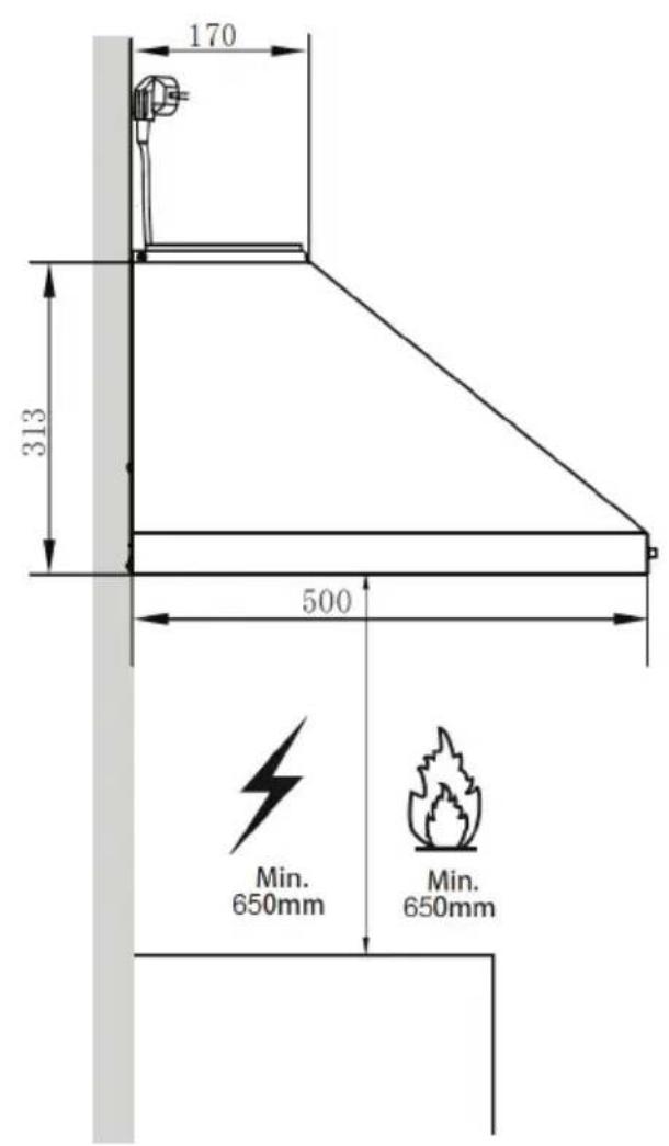
text_image
170 313 500 Min. 650mm Min. 650mmDimensions
text_image
170 172 226 229 A B 301 40 500 596natural_image
Technical line drawings of a mechanical bracket with multiple bolt holes and mounting points (no text or symbols)| Option Extraction X | |
| 1 400+0 / | |
| 2 400+300 390-620 | |
| 3 400+390 390-710 |
Lignes repères
text_image
Correct Incorrectnatural_image
Technical line drawing of a mechanical assembly with a magnified inset showing internal components (no text or symbols)PANNEAU DE COMMANDE ET FONCTIONS DES TOUCHES
Panneau de commande
text_image
Hand-drawn icons showing power, sun, wind, and light symbols with dashed outlinesnatural_image
Illustration of a hand pressing down on a device with a finger, showing a curved arrow (no text or symbols)natural_image
Pure mechanical diagram showing a rectangular frame with internal components and directional arrows, no text or symbols present.Démontage :
natural_image
Technical line drawing of a mechanical assembly with a hand holding a tool (no text or symbols present)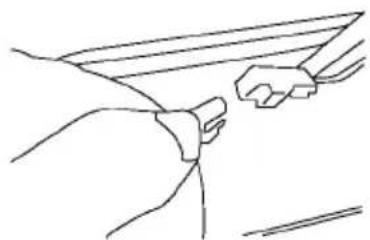
natural_image
Line drawing of a person's arm and hand holding a tool, no text or symbols present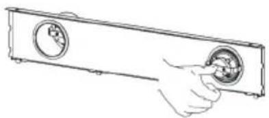
natural_image
Line drawing of a hand inserting a circular component into a rectangular device (no text or symbols)Lampe de rechange
| ∅ Puissance Tension Illustration | ILCOS D code | |||
| 70 mm 1,5 | W DC 12 V | 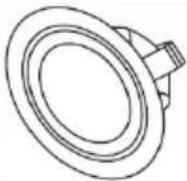 | DSR-1.5-S-70 | |
natural_image
Symbol of a trash bin crossed with a diagonal line, representing no waste or discharge (no text or labels)natural_image
Technical line drawing of a conical structure with a vertical dimension labeled 313 (no text or symbols beyond the dimension)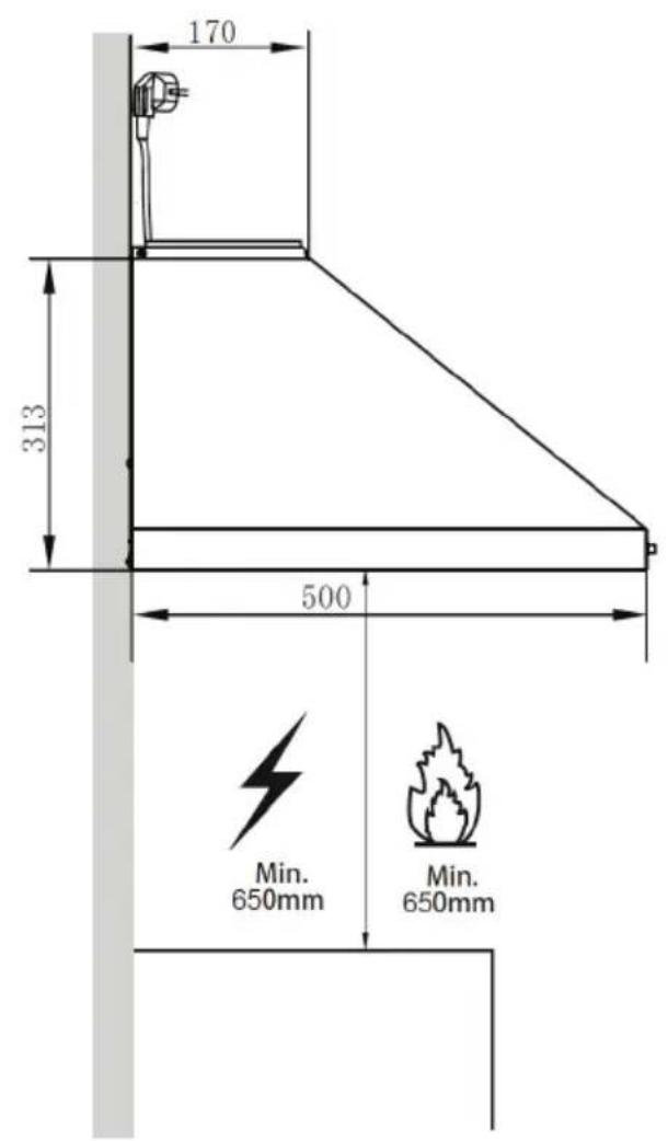
text_image
170 313 500 Min. 650mm Min. 650mmDimensioni
text_image
170 172 226 229 A B 301 40 500 596natural_image
Technical line drawings of a mechanical bracket with multiple bolt holes and mounting points (no text or symbols)| Opzione Camino X | |
| 1 400+0 / | |
| 2 400+300 390-620 | |
| 3 400+390 390-710 |