
TM-CAGE80 - Accessoires pour vidéoprojecteur VISION - Free user manual and instructions
Find the device manual for free TM-CAGE80 VISION in PDF.


User questions about TM-CAGE80 VISION
0 question about this device. Answer the ones you know or ask your own.
Ask a new question about this device
Download the instructions for your Accessoires pour vidéoprojecteur in PDF format for free! Find your manual TM-CAGE80 - VISION and take your electronic device back in hand. On this page are published all the documents necessary for the use of your device. TM-CAGE80 by VISION.
USER MANUAL TM-CAGE80 VISION
Congratulations on your choice of the Vision TM-CAGE TECHMOUNT. In order to obtain the best performance please be sure to read this owner's manual and use your product only in accordance with the instructions. An electronic version of this manual and further information can be found on www.visionaudiovisual.com
WARNINGS
During installation take care to adhere to workplace health and safety laws:
- Attach the bracket to a rated load-bearing structure. NEVER MOUNT CAGE OR BRACKET DIRECTLY TO A FALSE CEILING!
- Do not cut or drill any parts above head height. This should all be done using the correct safety equipment at floor level.
- Avoid overstretching which might result in the ladder tipping over.
- SWL (safe working load): 7kg
If you are unsure about the load-bearing capacity of the structure you are attaching the bracket to, we recommend testing it with your body weight by hanging off it gently. If you are uncomfortable doing this, it is probably not safe.
This product is a theft deterrent and does not guarantee the security of your projector. Alarm batteries should be tested at time of installation and annually. Vision's liability is limited to the terms set out in the warranty.
Vision is a partner in the TÜV SÜD product certification system. All applicable certification is provided by TÜV. All products are designed and imported into the EU by 'Vision' who is wholly owned by Azlan Logistics Ltd, Registered in England Nr. 04625566 at 'Lion House, Pioneer Business Park, Clifton Moor, York, YO30 4GH'
text_image
ReHS WEE/ABD047SY TUV SUD CECONTENTS
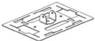
natural_image
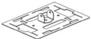
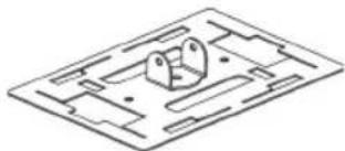
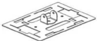
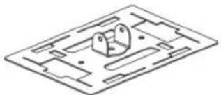
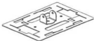
Isometric line drawing of a mechanical part with cutouts and mounting holes (no text or symbols)1 x Top Plate
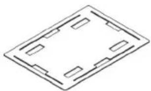
natural_image
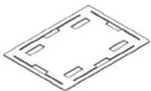
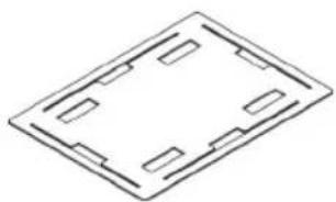
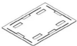
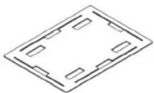
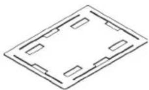
Isometric line drawing of a rectangular frame with four rectangular cutouts (no text or symbols)1 x Bottom Plate
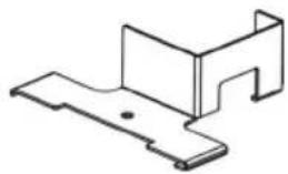
natural_image
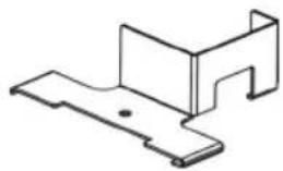
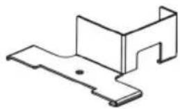
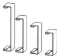
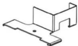
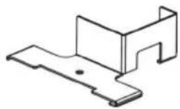
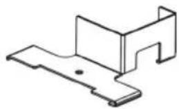
Isometric line drawing of a metal bracket or bracket (no text or symbols)2 x Access Prevention Collars
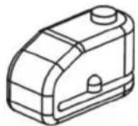
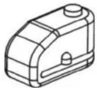
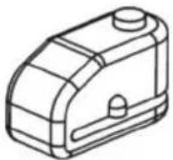
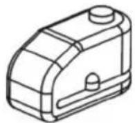
2 x Disc Locks
2 x Keys
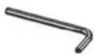
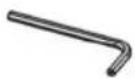
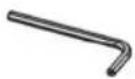
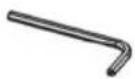
1 x Lock Hex Key
natural_image
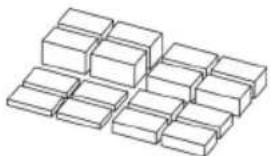
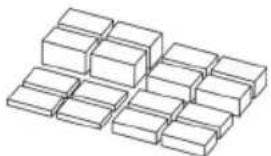
Isometric view of a grid of 12 rectangular blocks arranged in rows (no text or symbols)16 x Foam Blocks
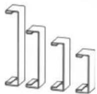
8 x Side Panels (Sold separately)
INSTALLATION INSTRUCTIONS
Note: For the most secure fit the cage should conform as closely as possible to the size of projector.
- Set bottom plate on level, non-scratch surface. It doesn't matter which way up it is.
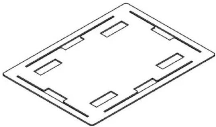
natural_image
Isometric line drawing of a rectangular frame with four internal slots and rectangular cutouts (no text or symbols)- Set four foam blocks on each corner of the bottom plate.
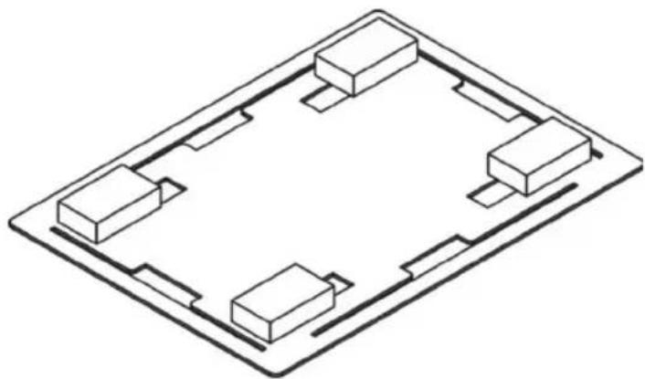
natural_image
Isometric line drawing of a rectangular electronic or architectural component with four internal compartments (no text or symbols)- Carefully put projector onto the foam blocks upside-down.
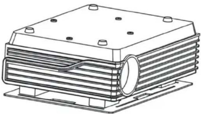
natural_image
Technical line drawing of a heat exchanger or cooling unit with multiple cooling fins and mounting base (no text or symbols)Note 1: Locate the foam blocks so they ARE NOT pushing function buttons on the top surface of the projector.
Note 2: The foam blocks come in four thicknesses to allow for projectors which do not have a flat top surface. Adjust to ensure the projector is level.
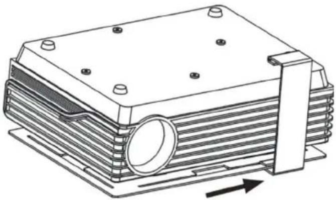
- Add side panels to LONG SIDES of bottom plate.
Step 1:
Lift bottom plate and hook the side panel in the notch at the centre.
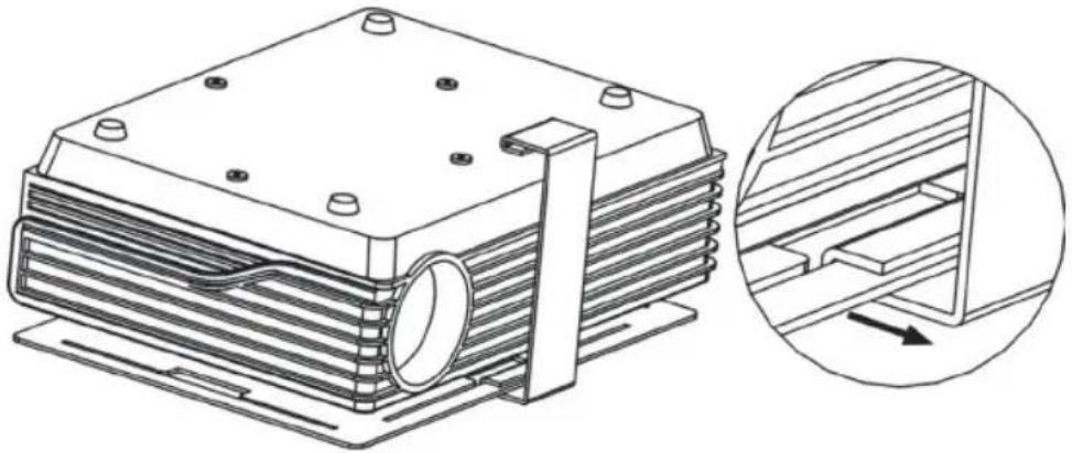
natural_image
Technical line drawing of a heat exchanger or cooling unit with a magnified inset showing internal structure (no text or symbols)Step 2:
Slide panel towards a corner until it stops.
natural_image
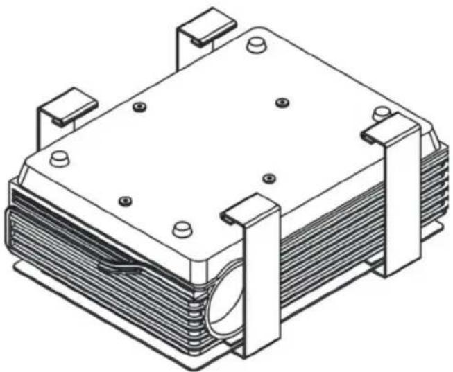
Technical line drawing of a mechanical component with layered structure and mounting holes (no text or symbols)Step 3:
Repeat until two side panels are installed on each long side.
natural_image
Isometric line drawing of a mechanical or electrical component with multiple mounting brackets and a central cylindrical component (no text or symbols)Note: If the projector lens prevents all eight from being installed then provided the cage is a close fit it should still be secure even if only seven side panels are installed. This is only true if the projector cannot be manoeuvred inside the cage.
- Fit top plate.
Step 1:
Locate the top plate over the projector and hook to the side panels already in place one side at a time. No force should be required.
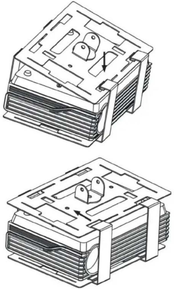
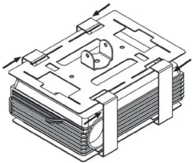
Step 2:
Slide the side panels towards the centre until they stop.
natural_image
Technical line drawing of a mechanical or electronic component with layered structure and directional arrows indicating movement (no text or symbols)- Add side panels to SHORT SIDES of bottom plate.
Step 1:
Lift bottom plate and hook the side panel in the notch at the centre.
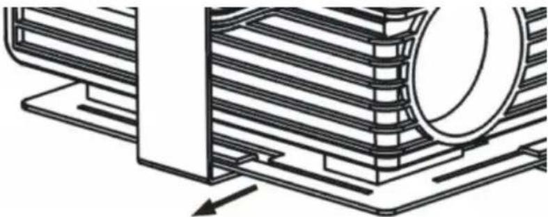
natural_image
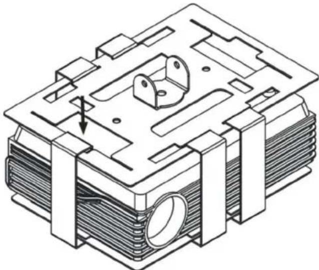
Technical line drawing of a mechanical component with layered structure and directional arrow (no text or symbols)Step 2:
Push the top plate down gently and hook the top of the side panel to the top plate.
natural_image
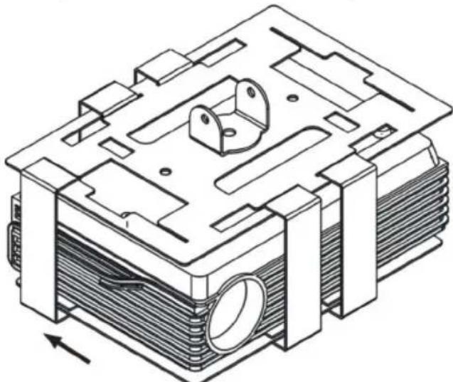
Technical line drawing of a mechanical housing or enclosure with internal components and mounting brackets (no text or symbols)Step 3:
Slide panel towards corner until it stops.
natural_image
Technical line drawing of a mechanical component with internal parts and mounting brackets (no text or symbols)Step 4:
Repeat until two side panels are installed on each short side.
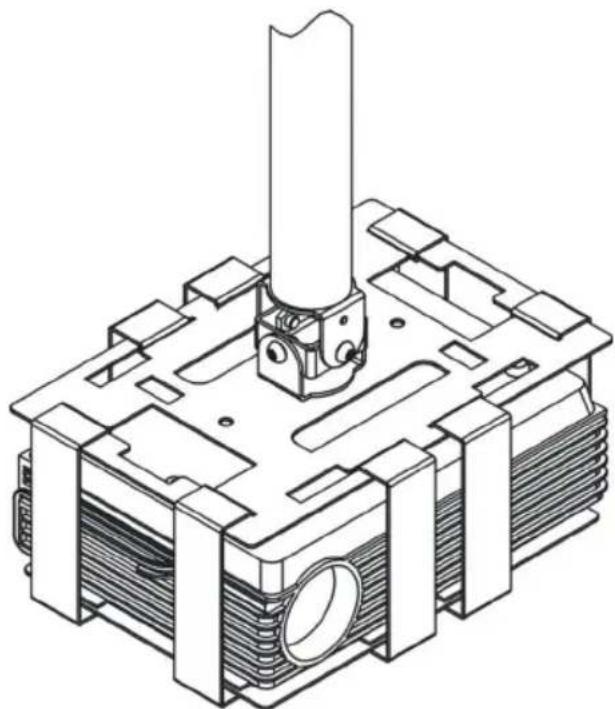
- Attach projector ceiling or wall mount.
natural_image
Technical line drawing of a mechanical component with no visible text or symbolsNote: This step is done with the projector bracket already in place in the ceiling.
Vision brackets attach to the TM-CAGE top plate with the pin-hex security bolts which come with Vision brackets.
- Route cables down the projector bracket and plug in to projector.
- Turn the projector on. Adjust the pitch and roll of the projector and tighten adjustment bolts.
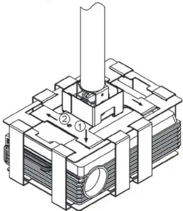
- Fit access prevention collars
text_image
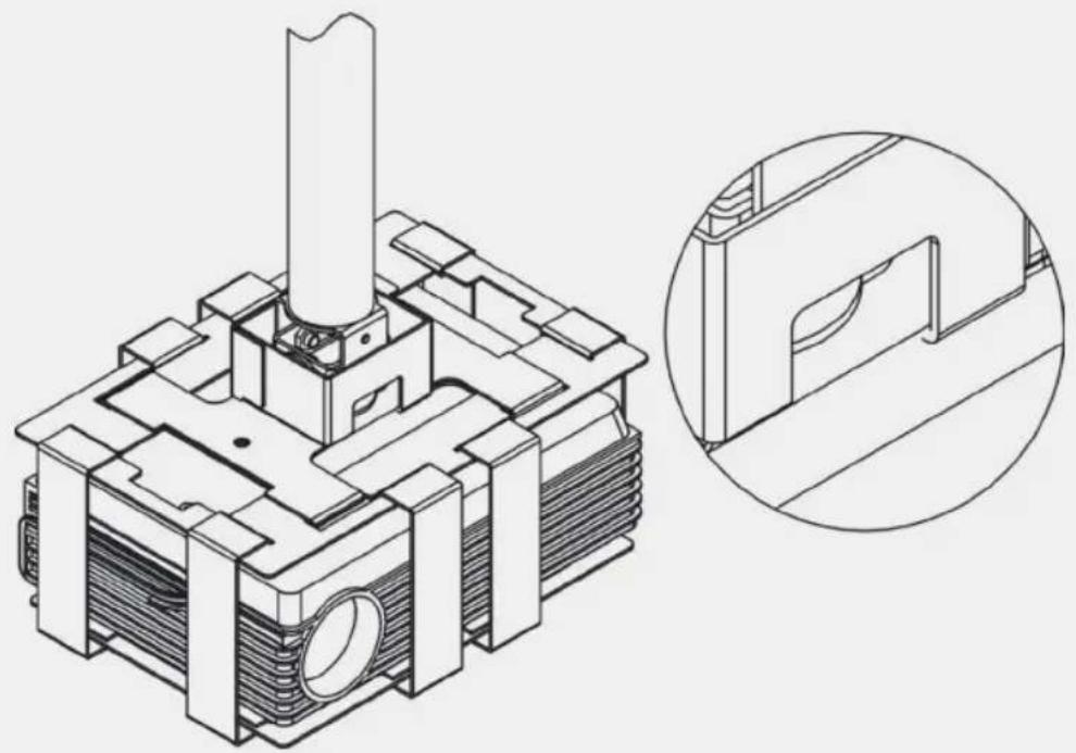
Technical diagram of a mechanical assembly with numbered components and directional arrows indicating flow or movement.Gently locate in the notch at each end of the long side, then slide into place. The 8mm hole on the top surface should be directly over the 8mm hole in the top plate.
Note: a notch at the bottom of the collar upright allows cables to be routed up the projector bracket pole into the ceiling.
natural_image
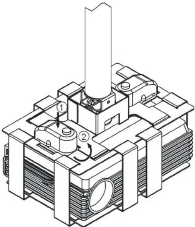
Technical line drawing of a mechanical component with cross-sectional view (no text or symbols)- Fit locks
Step 1:
Locate lock along the notch on the short side of the top plate.
text_image
Technical diagram of a mechanical or electrical component with numbered parts and directional arrows indicating flow or movement.Step 2:
Turn lock 90°. Locate locking pin over the 8mm hole on the top surface of the access prevention collar.
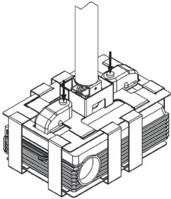
Step 3:
Push the lock to close it.
natural_image
Technical line drawing of a mechanical assembly with no visible text or symbolsLOCK INSTRUCTIONS
The lock comes with 6 x LR44 (AG13) batteries pre-installed in each lock.
- When locked, the lock will beep once to confirm it is armed. Then after 15 seconds it will become active.
- When the lock is moved it will give 3 warning beeps. After 5 seconds of continued movement the alarm will sound.
- When the alarm is sounding, if movement ceases for 35 seconds the alarm will stop sounding and return to active mode.
WARRANTY
This product comes with a 2-year return to base warranty, effective from the date of purchase. This warranty applies only to the original purchaser and is not transferable. For the avoidance of doubt, this will be taken from the information held by the appointed national distributor at the point of sale. The liability of the manufacturer and its appointed service company is limited to the cost of repair and or replacement of the faulty unit under warranty, except for death or injury (EU85/374/EEC). This warranty protects you against the following:
- Faulty wields resulting in the product not safely performing its task within the recommended SWL (safe working load).
- Poor finishing resulting in the product not being able to be assembled.
- External corrosion if identified within 24 hours of purchase. The inside of the pipe is not powder-coated, so light corrosion may develop over time. This is normal and does not adversely affect the load-bearing capability of the product, therefore it is not covered in this warranty.
If you find you do have a problem with this product, you should contact the AV reseller you purchased this product from. The original purchaser is responsible for shipment of the product to the manufacturer's appointed service centre for repair. We will endeavour to return repaired units within 5 working days, however this may not always be possible in which case it will be returned as soon as practically possible. This warranty does not protect this product against faults caused by abuse, misuse, or incorrect installation which might be caused by ignoring the guidelines set out in this manual. If failure is not covered by this warranty, the owner will be given the option to pay for labour and parts to repair the unit at the service company's standard rate.
ENGLISH


CAGE À PROJECTEUR TM TECHMOUNT GUIDE DE L'UTILISATEUR
text_image
ReHS WEE/AB0047SY TUV SUD CECONTENU
natural_image
Isometric technical drawing of a mechanical part with cutouts and mounting holes (no text or symbols)natural_image
Isometric line drawing of a rectangular frame with four rectangular cutouts (no text or symbols)natural_image
Isometric line drawing of a mechanical bracket or bracket (no text or symbols)natural_image
Isometric view of a grid of 12 rectangular blocks arranged in two rows (no text or symbols)natural_image
Isometric line drawing of a rectangular frame with internal slots and rectangular cutouts (no text or symbols)natural_image
Isometric line drawing of a rectangular electronic or architectural component with four internal compartments (no text or symbols)natural_image
Technical line drawing of a heat exchanger or cooling unit with multiple cooling fins and mounting base (no text or symbols)natural_image
Technical line drawing of a heat exchanger or cooling unit with a magnified inset showing internal structure (no text or symbols)Étape 2 :
natural_image
Technical line drawing of a multi-layered industrial or mechanical component with mounting holes and a central circular feature (no text or symbols)Étape 3 :
natural_image
Isometric technical drawing of a heat exchanger or cooling unit with mounting flanges and bolt holes (no text or symbols)natural_image
Technical line drawing of a mechanical or electronic component with layered structure and directional arrows indicating movement (no text or symbols)natural_image
Technical line drawing of a mechanical component with layered structure and directional arrow (no text or symbols)Étape 2 :
natural_image
Technical line drawing of a mechanical housing or enclosure with internal components and mounting brackets (no text or symbols)Étape 3 :
natural_image
Technical line drawing of a mechanical housing or enclosure with internal components and mounting brackets (no text or symbols)Étape 4 :
natural_image
Technical line drawing of a mechanical component with no visible text or symbolstext_image
Technical diagram of a mechanical assembly with numbered components and directional arrows indicating flow or movement.natural_image
Technical line drawing of a mechanical component with cross-sectional view (no text or symbols)natural_image
Technical line drawing of a mechanical assembly with no visible text or symbolsINSTRUCTIONS DE VERROUILLAGE
text_image
ReHS WEE/AB00475Y TUV SUD CECONTENIDOS
natural_image
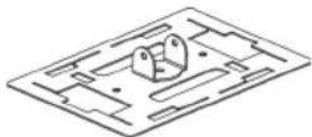
Isometric technical drawing of a mechanical part with cutouts and mounting holes (no text or symbols)1 x placa superior
natural_image
Isometric line drawing of a rectangular frame with four rectangular cutouts (no text or symbols)1 x placa inferior
natural_image
Isometric line drawing of a mechanical bracket or bracket (no text or symbols)natural_image
Isometric view of a grid of 12 rectangular blocks arranged in rows (no text or symbols)natural_image
Isometric line drawing of a rectangular electronic or architectural component with four internal compartments (no text or symbols)natural_image
Technical line drawing of a heat exchanger or cooling unit with multiple cooling fins and mounting base (no text or symbols)natural_image
Technical line drawing of a heat exchanger or cooling unit with a magnified inset showing internal structure (no text or symbols)Paso 2:
natural_image
Technical line drawing of a mechanical component with layered structure and mounting holes (no text or symbols)Paso 3:
natural_image
Isometric line drawing of a heat exchanger or cooling unit with mounting flanges and cooling fins (no text or symbols)natural_image
Technical line drawing of a mechanical or electronic component with layered structure and directional arrows indicating movement (no text or symbols)natural_image
Technical line drawing of a mechanical component with layered structure and directional arrow (no text or symbols)Paso 2:
natural_image
Technical line drawing of a mechanical housing or enclosure with internal components and mounting brackets (no text or symbols)Paso 3:
natural_image
Technical line drawing of a mechanical housing or enclosure with internal components and mounting brackets (no text or symbols)Paso 4:
natural_image
Technical line drawing of a mechanical component with no visible text or symbolstext_image
Technical diagram of a mechanical assembly with numbered components and directional arrows indicating flow or movement.natural_image
Technical line drawing of a mechanical component with cross-sectional view (no text or symbols)- Coloque los cierres
Paso 1:
natural_image
Technical line drawing of a mechanical assembly with no visible text or symbolstext_image
ReHS WEE/ABD0475Y TUV SUD CEINHOUD
natural_image
Isometric technical drawing of a mechanical part with cutouts and mounting holes (no text or symbols)1 x bovenplaat
natural_image
Isometric line drawing of a rectangular frame with four rectangular cutouts (no text or symbols)1 x onderplaat
natural_image
Isometric line drawing of a mechanical bracket or bracket (no text or symbols)2 x toegangsblokkerende kragen
2 x discussloten
2 x sleutels
1 x inbussleutel
natural_image
Isometric view of a grid of 12 rectangular blocks arranged in rows (no text or symbols)16 x schuimblokken
natural_image
Isometric line drawing of a rectangular electronic component with four internal blocks (no text or symbols)natural_image
Technical line drawing of a heat exchanger or cooling unit with layered insulation and mounting base (no text or symbols)natural_image
Technical line drawing of a heat exchanger or cooling unit with a magnified inset showing internal structure (no text or symbols)Stap 2:
natural_image
Technical line drawing of a mechanical component with mounting holes and a central circular feature (no text or symbols)Stap 3:
natural_image
Isometric line drawing of a heat exchanger or cooling unit with mounting brackets and internal coil (no text or symbols)natural_image
Technical line drawing of a mechanical or electronic component with layered structure and directional arrows indicating movement (no text or symbols)natural_image
Technical line drawing of a mechanical component with layered structure and directional arrow (no text or symbols)Stap 2:
natural_image
Technical line drawing of a mechanical housing or enclosure with internal components and mounting brackets (no text or symbols)Stap 3:
natural_image
Technical line drawing of a mechanical component with internal parts and mounting brackets (no text or symbols)Stap 4:
natural_image
Technical line drawing of a mechanical component with no visible text or symbolsLet op: Deze stap
text_image
Technical diagram of a mechanical assembly with numbered components and directional arrows indicating flow or movement.natural_image
Technical line drawing of a mechanical component with cross-sectional view (no text or symbols)- Sloten plaatsen
Stap 1:
text_image
Technical diagram of a mechanical assembly with numbered components and directional arrows indicating motion or flow.Stap 2:
natural_image
Technical line drawing of a mechanical assembly with no visible text or symbolsSLUITINGSVOORSCHRIFTEN
natural_image
Isometric technical drawing of a mechanical part with cutouts and mounting holes (no text or symbols)1 x Deckplatte
natural_image
Isometric line drawing of a rectangular frame with four rectangular cutouts (no text or symbols)1 x Grundplatte
natural_image
Isometric line drawing of a mechanical bracket or bracket (no text or symbols)2 x Abdeckbleche
2 x Sperrbügel
2 x Schlüssel
natural_image
Isometric view of a grid of 12 rectangular blocks arranged in rows (no text or symbols)natural_image
Isometric line drawing of a rectangular frame with internal slots and cutouts (no text or symbols)natural_image
Isometric line drawing of a rectangular electronic or architectural component with four internal compartments (no text or symbols)natural_image
Technical line drawing of a heat exchanger or cooling unit with multiple cooling fins and mounting base (no text or symbols)natural_image
Technical line drawing of a heat exchanger or cooling unit with a magnified inset showing internal structure (no text or symbols)Schritt 2:
natural_image
Technical line drawing of a multi-layered industrial or mechanical component with mounting holes and a central circular feature (no text or symbols)Schritt 3:
natural_image
Isometric line drawing of a heat exchanger or cooling unit with mounting brackets and internal cooling fins (no text or symbols)natural_image
Technical line drawing of a mechanical or electronic component with layered structure and mounting brackets (no text or symbols)natural_image
Technical line drawing of a mechanical component with layered structure and directional arrow (no text or symbols)Schritt 2:
natural_image
Isometric technical drawing of a mechanical housing or enclosure with internal components and mounting brackets (no text or symbols)Schritt 3:
natural_image
Technical line drawing of a mechanical housing or enclosure with internal components and mounting brackets (no text or symbols)Schritt 4:
natural_image
Technical line drawing of a mechanical component with no visible text or symbolstext_image
Technical diagram of a mechanical assembly with numbered components and directional arrows indicating flow or movement.natural_image
Technical line drawing of a mechanical component with cross-sectional view (no text or symbols)text_image
Technical diagram of a mechanical assembly with numbered components and directional arrows indicating motion or flow.Schritt 2:
natural_image
Technical line drawing of a mechanical assembly with no visible text or symbolstext_image
ReHS WEE/ABD0475Y TUV SUD CECONTENUTO
natural_image
Isometric line drawing of a mechanical part with cutouts and mounting holes (no text or symbols)natural_image
Isometric line drawing of a rectangular frame with four rectangular cutouts (no text or symbols)natural_image
Isometric line drawing of a mechanical bracket or bracket (no text or symbols)2 x collari antintrusione
2 x blocchi a disco
2 x chiavi
natural_image
Isometric view of a grid of 12 rectangular blocks arranged in rows (no text or symbols)natural_image
Isometric line drawing of a rectangular frame with four internal slots and rectangular cutouts (no text or symbols)natural_image
Isometric line drawing of a rectangular electronic component with four internal blocks (no text or symbols)natural_image
Technical line drawing of a heat exchanger or cooling unit with multiple cooling fins and mounting base (no text or symbols)natural_image
Technical line drawing of a multi-layered industrial cooling unit with a magnified inset showing internal structure (no text or symbols)Passo 2:
natural_image
Technical line drawing of a mechanical component with layered structure and mounting holes (no text or symbols)Passo 3:
natural_image
Isometric line drawing of a heat exchanger or cooling unit with mounting brackets and internal coil (no text or symbols)natural_image
Technical line drawing of a mechanical or electronic component with layered structure and directional arrows indicating movement (no text or symbols)natural_image
Technical line drawing of a mechanical component with layered structure and directional arrow (no text or symbols)Passo 2:
natural_image
Technical line drawing of a mechanical housing or enclosure with internal components and mounting brackets (no text or symbols)Passo 3:
natural_image
Technical line drawing of a mechanical housing or enclosure with internal components and mounting brackets (no text or symbols)Passo 4:
natural_image
Technical line drawing of a mechanical component with no visible text or symbolstext_image
Technical diagram of a mechanical assembly with numbered components and directional arrows indicating flow or movement.natural_image
Technical line drawing of a mechanical component with cross-sectional view (no text or symbols)- Montare i blocchi
Passo 1:
text_image
Technical diagram of a mechanical assembly with numbered components and directional arrows indicating motion or flow.Passo 2:
natural_image
Technical line drawing of a mechanical assembly with no visible text or symbolsISTRUZIONI RELATIVE AI BLOCCHI
text_image
ReHS WEE/AB00475Y TUV SUD CEZAWARTOŚĆ OPAKOWANIA
natural_image
Isometric line drawing of a mechanical component with no visible text or symbols1 x płyta górna
natural_image
Isometric line drawing of a rectangular frame with four rectangular cutouts (no text or symbols)1 x płyta dolna
natural_image
Isometric line drawing of a mechanical bracket or bracket (no text or symbols)natural_image
Isometric view of a grid of 12 rectangular blocks arranged in rows (no text or symbols)natural_image
Isometric line drawing of a rectangular frame with four rectangular cutouts (no text or symbols)natural_image
Isometric line drawing of a rectangular electronic or mechanical component with four internal blocks (no text or symbols)natural_image
Technical line drawing of a heat exchanger or cooling unit with multiple cooling fins and mounting holes (no text or symbols)natural_image
Technical line drawing of a heat exchanger or cooling unit with a magnified inset showing internal structure (no text or symbols)Krok 2:
natural_image
Technical line drawing of a mechanical component with layered structure and mounting holes (no text or symbols)Krok 3:
natural_image
Isometric line drawing of a heat exchanger or cooling unit with mounting flanges and cooling fins (no text or symbols)natural_image
Technical line drawing of a mechanical or electronic component with layered structure and mounting brackets (no text or symbols)natural_image
Technical line drawing of a mechanical component with layered structure and directional arrow (no text or symbols)Krok 2:
natural_image
Isometric technical drawing of a mechanical housing or enclosure with internal components and mounting brackets (no text or symbols)Krok 3:
natural_image
Technical line drawing of a mechanical housing or enclosure with internal components and mounting brackets (no text or symbols)Krok 4:
natural_image
Technical line drawing of a mechanical component with no visible text or symbolstext_image
Technical diagram of a mechanical assembly with numbered components and directional arrows indicating flow or movement.natural_image
Technical line drawing of a mechanical component with a magnified inset showing internal structure (no text or symbols)natural_image
Technical line drawing of a mechanical assembly with no visible text or symbolsINSTRUKCJE DOTYCZĄCE ELEMENTÓW BLOKUJĄCYCH
text_image
RoHS WEE/AB0047SY TUV SUD CEÍNDICE
natural_image
Isometric technical drawing of a mechanical part with cutouts and mounting holes (no text or symbols)1 Placa de topo
natural_image
Isometric line drawing of a rectangular frame with four rectangular cutouts (no text or symbols)1 Placa de base
natural_image
Isometric line drawing of a metal bracket or bracket (no text or symbols)natural_image
Isometric view of a grid of 12 rectangular blocks arranged in rows (no text or symbols)natural_image
Isometric line drawing of a rectangular frame with four rectangular cutouts and a central rectangular space (no text or symbols)natural_image
Isometric line drawing of a rectangular electronic component with four internal blocks (no text or symbols)natural_image
Technical line drawing of a heat exchanger or cooling unit with multiple cooling fins and mounting tabs (no text or symbols)natural_image
Technical line drawing of a heat exchanger or cooling unit with a magnified inset showing internal structure (no text or symbols)Passo 2:
natural_image
Technical line drawing of a mechanical component with layered structure and mounting holes (no text or symbols)Passo 3:
natural_image
Isometric technical drawing of a heat exchanger or cooling unit with mounting brackets and internal components (no text or symbols)natural_image
Technical line drawing of a mechanical or electronic component with layered structure and directional arrows indicating movement (no text or symbols)- Monte painéis laterais nos LADOS MENORES da placa de base.
Passo 1:
natural_image
Technical line drawing of a mechanical component with layered structure and directional arrow (no text or symbols)Passo 2:
natural_image
Isometric technical drawing of a mechanical housing or enclosure with internal components and mounting brackets (no text or symbols)Passo 3:
natural_image
Technical line drawing of a mechanical component with internal channels and mounting brackets (no text or symbols)Passo 4:
natural_image
Technical line drawing of a mechanical component with no visible text or symbolstext_image
Technical diagram of a mechanical assembly with numbered components and directional arrows indicating flow or movement.natural_image
Technical line drawing of a mechanical component with cross-sectional view (no text or symbols)- Instale os bloqueadores.