
ROYAL 50 S BBC - Motorcycle HUSQVARNA - Free user manual and instructions
Find the device manual for free ROYAL 50 S BBC HUSQVARNA in PDF.
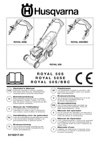


| Product type | Self-propelled lawn mower |
| Brand | Husqvarna |
| Model | Royal 50 S BBC |
| Power source | Unleaded gasoline |
| Engine type | 4-stroke |
| Starting type | Automatic recoil starter |
| Cutting system | Rotary blade with blade brake clutch (BBC) |
| Grass catcher | Yes, with fill indicator |
| Mulching insert | Yes (optional, included) |
| Cutting height adjustment | By lever, multiple positions |
| Drive speed adjustment | By variable speed control (model with BBC) |
| Maintenance - Oil change | Every 25 hours of use |
| Maintenance - Blade replacement | Every 50 hours or every 2 years |
| Maintenance - Cleaning | Using a brush, no water |
| Safety - Engine brake | Yes, with safety bar |
| Safety - Emergency stop | Release the traction bar or BBC |
| Recommended engine oil | Good quality SAE 30 |
| Engine warranty | By the manufacturer (Briggs & Stratton) |
Frequently Asked Questions - ROYAL 50 S BBC HUSQVARNA
User questions about ROYAL 50 S BBC HUSQVARNA
0 question about this device. Answer the ones you know or ask your own.
Ask a new question about this device
Download the instructions for your Motorcycle in PDF format for free! Find your manual ROYAL 50 S BBC - HUSQVARNA and take your electronic device back in hand. On this page are published all the documents necessary for the use of your device. ROYAL 50 S BBC by HUSQVARNA.
USER MANUAL ROYAL 50 S BBC HUSQVARNA
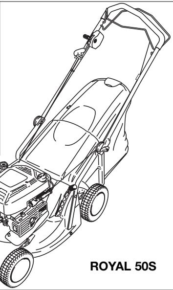
ROYAL 50SE
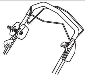
ROYAL 50S/BBC

ROYAL 50S
ROYAL 50SE
ROYAL 50S/BBC
CE
GB
Operator's Manual
Read the operator's manual carefully and make sure that you understand the contents before using the lawnmower.
D
Betriebsanleitung
- Handle Assembly
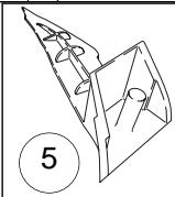
- Grassbox
- Bottle of oil
- Instruction Manual
- Mulching Plug
- Key Start (Royal 50SE)
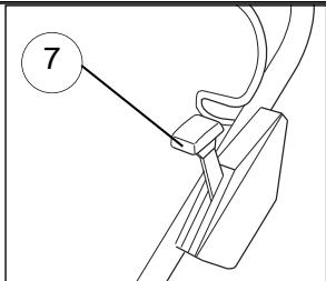
- BBC Lever (Royal 50S/BBC)
- Warning Label
- Rating Label
- Battery Charger (Royal 50SE)
D - CONTENTS
(A) ROYAL 50SE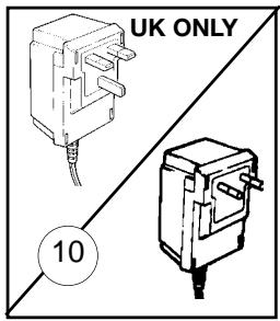
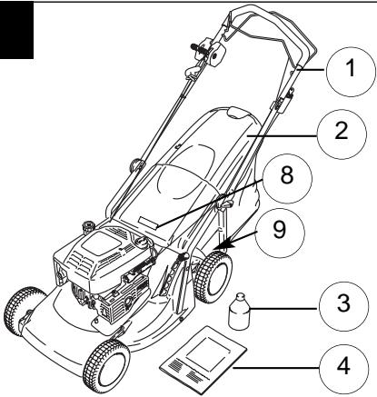
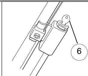
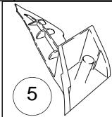
(A) ROYAL 50S/BBC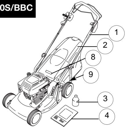
SAFETY PRECAUTIONS

If not used properly this lawnmower can be dangerous! This lawnmower can cause serious injury to the operator and others, the warnings and safety instructions must be followed to ensure reasonable safety and efficiency in using this lawnmower. The operator is responsible for following the warning and safety instructions in this manual and on the lawnmower.
Never use the mower unless the grassbox or guards provided by the manufacturer are in position.
Explanation of Symbols on your Husqvarna Royal 50S, 50SE & 50SBBC

Warning

Read the user instructions carefully to make sure you understand all the controls and what they do.
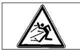
Always keep the lawnmower on the ground when mowing. Tilting or lifting the lawnmower may cause stones to be thrown out.
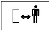
Keep bystanders away. Do not mow whilst people, especially children or pets, are in the mowing area.
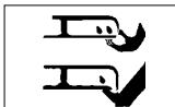
Beware of severing toes or hands. Do not put hands or feet near a rotating blade.
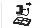
Disconnect the spark plug before attempting any maintenance, cleaning, or adjustment, or if you are going to leave the lawnmower unattended for any period.

Blade continues to rotate after the machine is switched off. Wait until all machine components have completely stopped before touching them.
General
- Never allow children or people unfamiliar with these instructions to use the mower. Local regulations may restrict the age of the operator.
- Only use the lawnmower in the manner and for the functions described in these instructions.
- Never operate the lawnmower when you are tired, ill, or under the influence of alcohol, drugs, or medicine.
- The operator or user is responsible for accidents or hazards occurring to other people or their property.
Fuel Safety WARNING - Petrol is highly flammable.
- Store fuel in a cool place in a container specifically designed for the purpose. In general, plastic containers are unsuitable.
- Refuel outdoors only and do not smoke while refuelling.
- Add fuel BEFORE starting the engine. Never remove the cap of the fuel tank or add fuel while the engine is running or when the engine is hot.
- If petrol is spilled, do not attempt to start the engine but move the machine away from the area of spillage and avoid creating any source of ignition until petrol vapours have dissipated.
- Replace all fuel tanks and container caps securely.
- Move the product away from the fuelling area before starting.
Safety Procedures when Charging the Battery (ROYAL 50SE)
- Check the charger cable regularly for damage or deterioration due to age.
- Do not use the lawnmower if the charging cable is not in good condition.
- Do not attempt to charge other products with the charger from this unit.
- Do not attempt to use this battery with any other charger.
- Charging should only be carried out in a safe location where neither battery nor cord cable can be trodden on or tripped over.
- Location should be well-ventilated.
- During charging, the battery charger becomes warm. This is normal and means the charger is operating properly.
- Do not cover the battery charger with anything during charging.
- Ensure that neither the charger nor the battery are exposed to moisture.
- Avoid extreme temperatures.
- The charger will not operate below freezing point nor above 40°C.
- Do not short circuit the battery terminals.
SAFETY PRECAUTIONS
Preparation
- Do not mow barefoot or in open sandals. Always wear suitable clothing, gloves, and stout shoes.
- The use of ear protection is recommended.
- Make sure the lawn is clear of sticks, stones, bones, wire and debris; they could be thrown by the blade.
- Before using always visually inspect to see that blades, blade bolts and cutter assembly are not worn or damaged. Replace worn or damaged blades together with their fixings in sets to preserve balance.
- Have faulty silencers replaced.
Use
- Do not operate the engine in a confined space where exhaust fumes (carbon monoxide) can collect.
- Use the lawnmower only in daylight or good artificial light.
- Avoid operating your lawnmower in wet grass, where feasible.
- Take care in wet grass, you may lose your footing.
- On slopes, be extra careful of your footing and wear non-slip footwear.
- Mow across the face of slopes, never up and down.
- Exercise extreme caution when changing direction on slopes.
- Mowing on banks and slopes can be dangerous. Do not mow on banks or steep slopes.
- Do not walk backwards when mowing, you could trip. Walk never run.
- Never cut grass by pulling the mower towards you.
- Stop the engine before pushing the mower across surfaces other than grass and when transporting the lawnmower to and from the area to be mowed.
- Never operate the lawnmower with damaged guards or without guards in place.
- Do not overspeed the engine or alter governor settings. Excessive speed is dangerous and shortens lawnmower life.
- Disengage all blade and drive clutches before starting.
- Always start the lawnmower carefully with feet well away from the blades.
- Do not tilt lawnmower when starting the engine.
- Do not put hands near the grass discharge chute whilst engine is running.
- Never pick up or carry a lawnmower while the engine is running.
- Spark plug wire may be hot - handle with care.
- Do not attempt any maintenance on your lawnmower when the engine is hot.
- Stop the engine, and wait until the blade has stopped:-
- before leaving the mower unattended for any period;
- Stop the engine, wait until the blade has stopped and disconnect the spark plug lead:-
- before refuelling
- before clearing a blockage;
- before checking, cleaning or working on the appliance;
- if you hit an object. Do not use your lawnmower until you are sure that the entire lawnmower is in a safe operating condition.;
- if the lawnmower starts to vibrate abnormally. Check immediately. Excessive vibration can cause injury.
- Reduce the throttle setting during engine shut down and, if the engine is provided with a shut-off valve, turn the fuel off at the conclusion of mowing.
Maintenance and storage
- Keep all nuts, bolts and screws tight to be sure the lawnmower is in safe working condition.
- Check the grassbox/grassbag frequently for wear or deterioration. Replace worn or damaged parts for safety.
- Only use the replacement blade, blade bolt, spacer and impeller specified for this product.
- Never store the lawnmower with fuel in the tank inside a building where fumes can reach an open flame or spark.
- Allow the engine to cool before storing in any enclosure.
- To reduce fire hazard, keep the engine, silencer, battery compartment and fuel storage area free of grass, leaves or excessive grease.
- If the fuel tank has to be drained, this should be done outdoors.
- Be careful during adjustment of the machine to prevent entrapment of the fingers between moving blades and fixed parts of the machine.
PRODUCT RATING LABEL
B
Product Number ....
Model Number ....
Serial Number.....
Date of Purchase ....
Place of Purchase....
- PLEASE KEEP PROOF OF PURCHASE-
Your product is uniquely identified by a silver and black product rating label. To ensure you have full product information when obtaining spares or advice from one of our approved service centres or if you need to contact our customer service department you should make a note in the space provided of the information shown in Fig B
ASSEMBLY INSTRUCTIONS
Handle Assembly
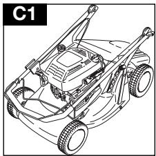
- Your product is supplied with the handles folded over the product. (C1)
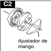
- Loosen handle adjusters (C2) on both sides of the product and lift handle assembly up.
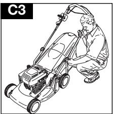
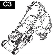
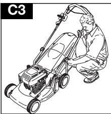
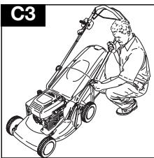
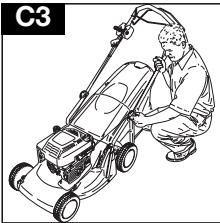
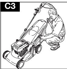
- Adjust handle assembly to the most comfortable operating position (C3) and tighten handle adjusters (C2) on both sides of the product.
Recoil Starter
- Disconnect the spark plug lead.
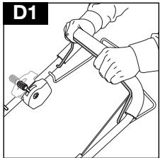
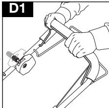
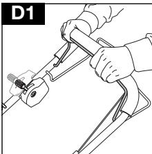
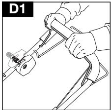
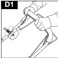
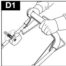
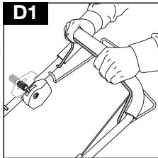
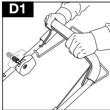
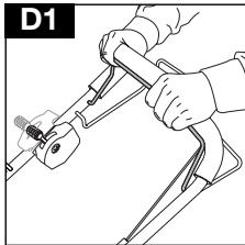
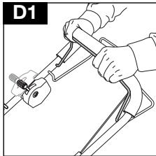
- Pull the Operator Presence Control (D1) to release the brake on the engine. ROYAL 50S AND ROYAL 50SE ONLY
You must release the brake by pulling the OPC lever to the handle before pulling out the cord.
C2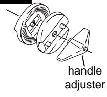
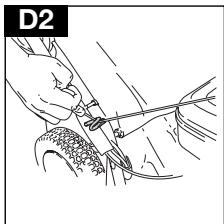
- Locate cord in the pull cord guide on the lower handle. (D2)
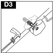
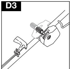
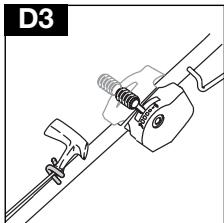
- Locate cord in the pull cord guide on the upper handle. (D3)
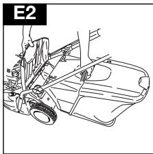
Fitting the Grassbox
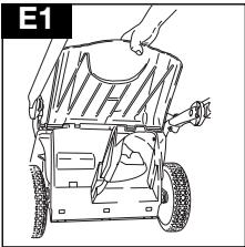
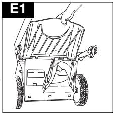
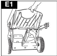
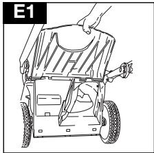
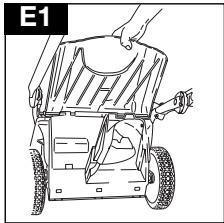
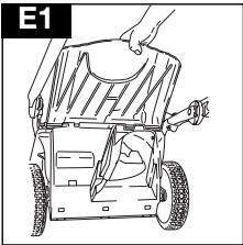
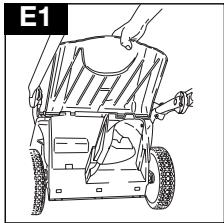
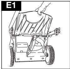
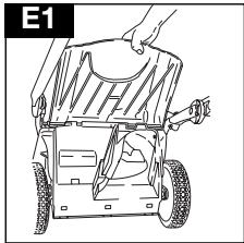
- Lift safety flap. (E1)
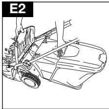
- Locate grassbox to machine. (E2)
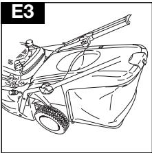
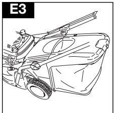
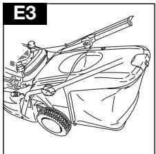
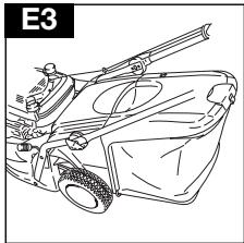
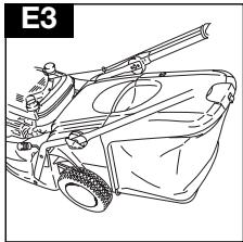
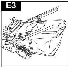
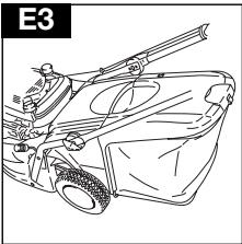
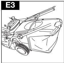
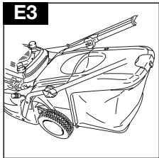
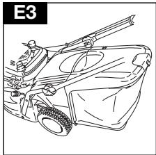
- Locate safety flap onto the top of the grassbox. (E3). Ensure the grassbox is securely located.
E2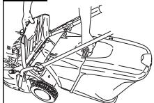
D2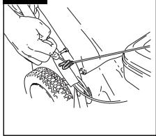
D3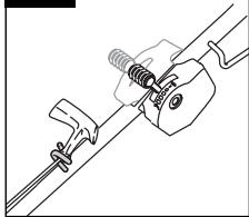
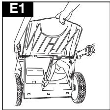
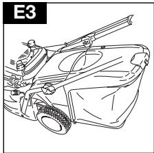
Please Note: Ensure no gap remains between the safety flap and the grassbox.
Where grass collection is not required you can use the lawnmower without the grassbox. Ensure the safety flap is fully closed.
ENGINE NOTES
Oil
- Check oil level periodically and after every five hours of operation.
- Add oil as necessary to keep the level to the FULL mark on the dipstick.
- Use a good quality SAE 30 four stroke oil.
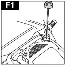
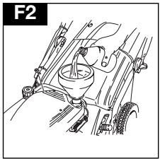
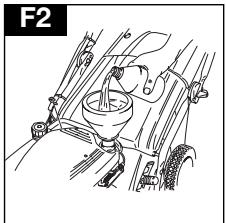
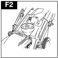
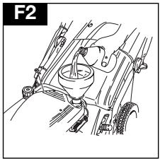
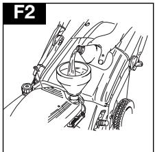
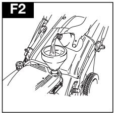
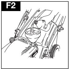
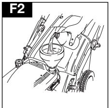
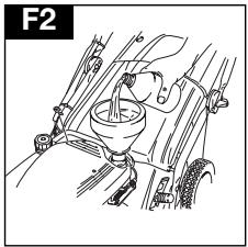
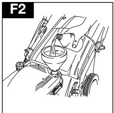
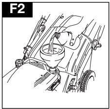
- To fill with oil:- a) Remove oil filler cap. (F1) b) Fill to the FULL mark on the dipstick. (F2)
- Change the oil after the first five hours of operation and thereafter every 25 working hours.
- Always change the oil while the engine is warm - but not hot - never attempt any maintenance on a hot engine.
Petrol
- Use fresh regular grade lead-free petrol.
- Do not fill the fuel tank when the engine is hot.
- Do not fill the fuel tank while smoking.
- Do not fill the fuel tank while the engine is
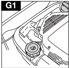
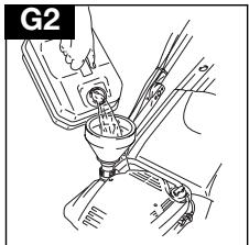
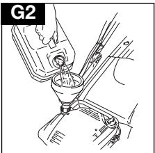
running. 5. To avoid introducing dirt into the fuel system, wipe all grass and dirt from the petrol filler cap before unscrewing it. (G1)
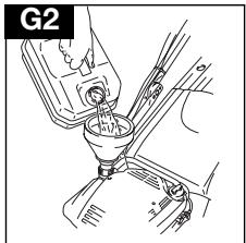
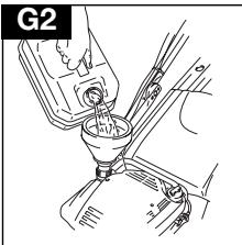
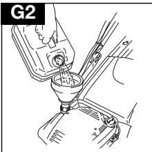
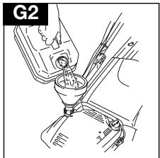
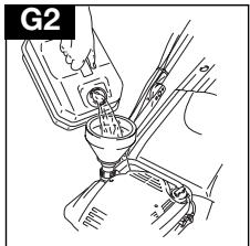
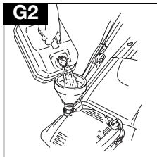
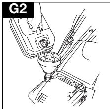
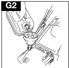
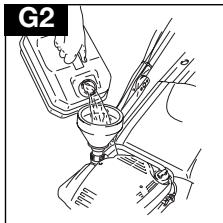
- It is recommended that you fill the tank through a funnel with a filter. (G2)
- Wipe away spillages before starting.
Please Note: move the product away from the fuelling area before starting.
STARTING - PRIMING THE ENGINE
Please Note: When starting the engine for the first time, fill with oil and petrol as described above in the Oil and Petrol section.
Priming is usually unnecessary when restarting a warm engine. However, cool weather may require priming to be repeated.
Starting the engine for the first time
- Advance engine speed control to FAST '+' as illustrated in the Use - starting and stopping section.
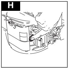
- Push primer bulb (H) firmly five times.
- Follow instructions in the Use - starting and stopping section.
- If engine fails to start after three pulls of the pull cord, push primer bulb three times and repeat step 3.
Starting engine thereafter
- Move engine speed control to FAST '+' position and push primer bulb firmly three times before starting engine. (If engine stopped because it ran out of fuel, refuel engine - push primer bulb three times.)
USE - STARTING AND STOPPING
Starting & Stopping Royal 50S
Starting
- Connect the spark plug lead.
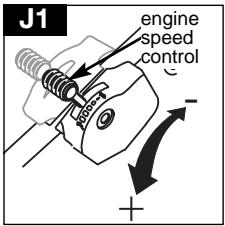
- Move the Engine Speed Control to the FAST '+' position before starting. (J1)
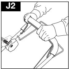
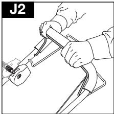
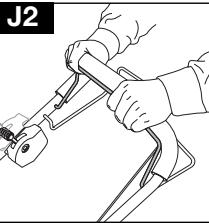
- Pull the operator presence control (OPC) to release the brake on the engine and the blade. (J2)
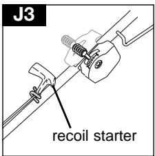
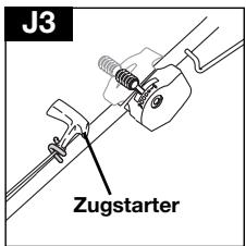
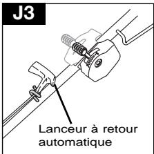
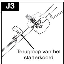
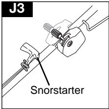
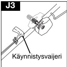
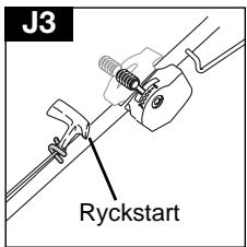
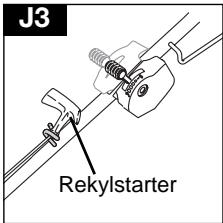
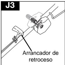
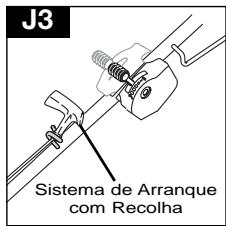
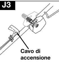
- Pull the recoil starter fully towards you until you feel the full resistance, return the handle slowly then pull the handle firmly towards you to its full extent. (J3)
- After the engine has started, allow to run for 30 seconds before commencing to use.
Engaging the Drive
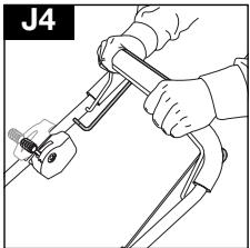
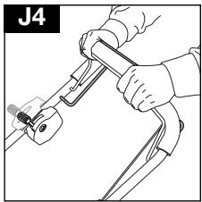
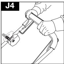
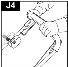
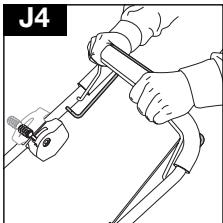
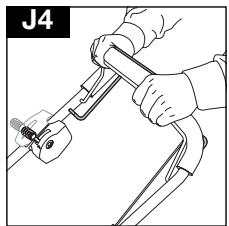
- Forward drive is engaged and disengaged with the Powerdrive lever at the top of the handle (J4).
- Releasing the Powerdrive Lever stops the forward drive automatically.
Stopping
- Release the powerdrive lever.
- Release the OPC lever.
Starting & Stopping Royal 50SE
Starting
- Follow steps 1-3 for the Royal 50S
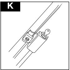
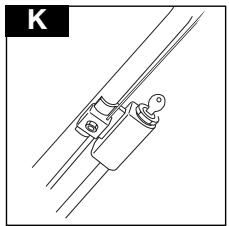
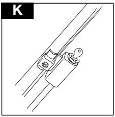
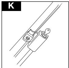
- Turn the key and hold until the engine starts (K). The key will return to the original position when released.
- If the engine fails to start when you turn the key, your battery may not be charged.
Engaging the Drive - See Royal 50S
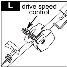
Drive speed can be altered with the drive speed control. (L)
Stopping - See Royal 50S
Please note: Your Royal 50SE can be started manually by following steps 1-5 in Starting & Stopping Royal 50S
Key Start Only - During mowing, your engine will recharge the battery
Starting & Stopping Royal 50S/BBC (BBC - Blade, Brake, Clutch)
- Follow steps 1 - 2 - 4 and 5 for the Royal 50S.
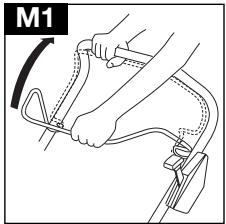
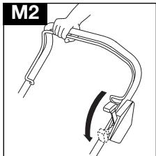
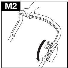
- Pull the BBC arm to the handle (M1).
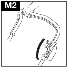
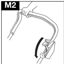
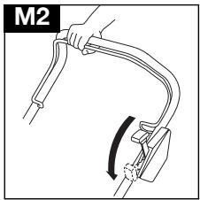
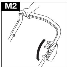
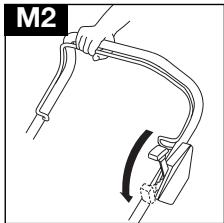
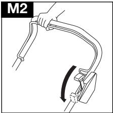
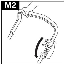
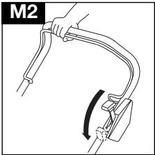
- While holding the BBC arm, push forward the BBC control lever until a click is heard (M2).
- Release the BBC control lever, which will return to its original position.
- Releasing the BBC arm will stop the blade from rotating.
Please Note:
Leaving the engine running without the blade rotating for an extended length of time could lead to the engine overheating.
Engaging the Drive - See Royal 50S
Drive speed can be altered with the drive speed control. (L)
Stopping
- Release the powerdrive lever.
- Release the BBC arm.
- Move Engine Speed Control to the '-' position.
How to Mow
- Always use the correct mowing position (N1).
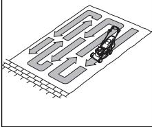
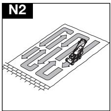
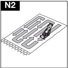
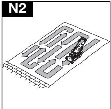
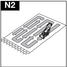
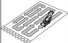
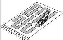
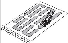
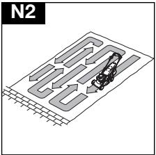
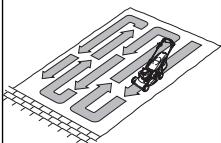
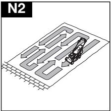
- Start mowing from the outside edge of the lawn, mowing in strips in alternate directions (N2).
- Mow twice a week in the growing season, your lawn will suffer if more that one third of its length is cut at one time and this may also result in poor collection.
N1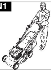
N2
Please Note:-
Do not overload your lawnmower.
When mowing in long thick grass, a first cut with the cutting height adjusted to its highest setting (see Cutting Height) will help reduce engine overload and will help prevent damage to your lawnmower.
Cutting Height
Adjustment
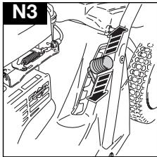
- The height of cut is altered by pulling the adjustment lever away from the location slots and moving to the selected position (N3).
Grass Collection Indicator
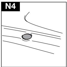
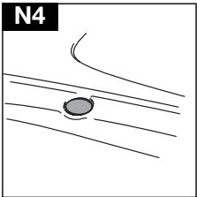
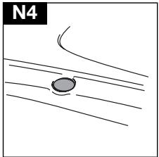
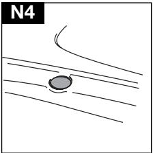
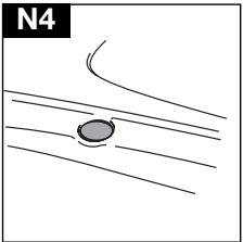
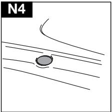
- Your lawnmower has a grass collection indicator which tells you when the grassbox needs emptying. (N4)
- When the indicator is at the top of the tube, grass is being collected.
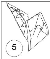
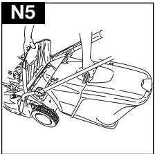
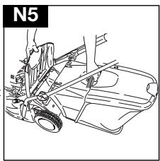
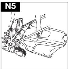
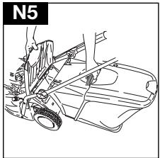
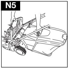
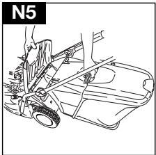
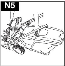
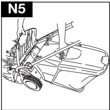
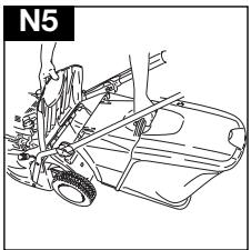
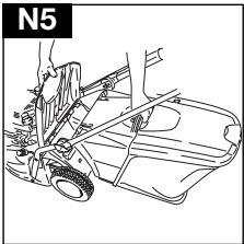
- When the indicator starts to drop, it's time to empty the grassbox. Adopt a stationary position, keeping the lawnmower running for 10 seconds. Release the OPC lever or BBC arm and remove the grassbox for emptying. (N5)
N4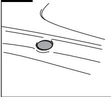
Emptying the Grassbox
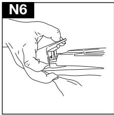
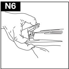
- Release the latch on the grassbox. (N6)
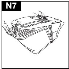
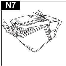
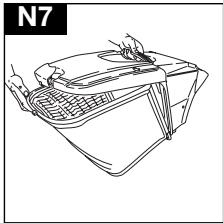
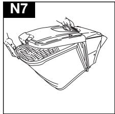
- Release collection bag from grassbox frame. (N7)
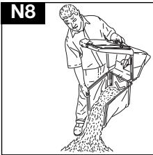
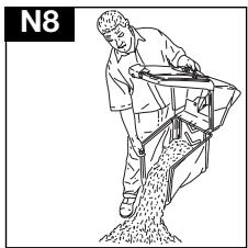
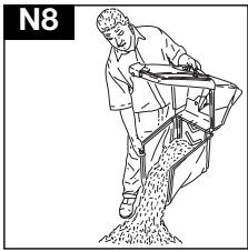
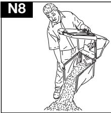
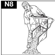
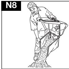
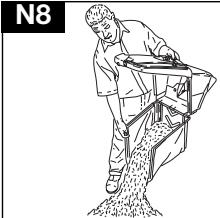
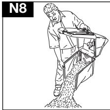
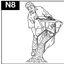
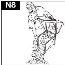
- Empty grassbox. (N8)
N7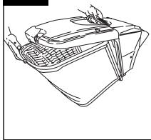
Using as a mulcher
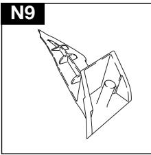
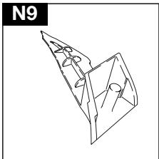
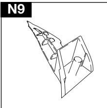
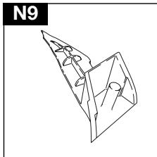
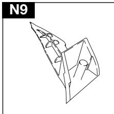
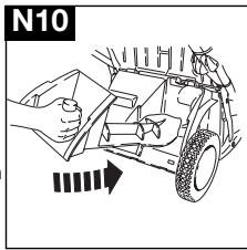
- Your lawnmower is supplied with a mulching plug. (N9)
- Stop your lawnmower as described in Use - starting and stopping, and disconnect the spark plug.
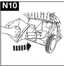
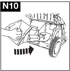
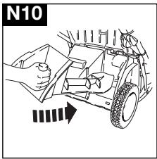
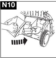
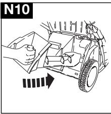
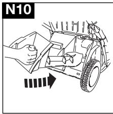
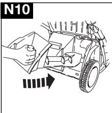
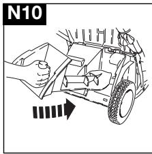
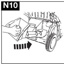
- Lift safety flap. Twist and slide mulching plug into rear discharge chute. (N10)
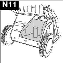
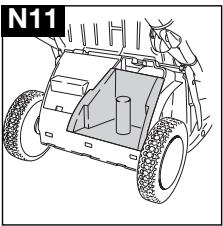
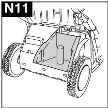
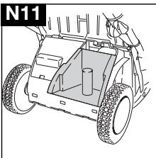
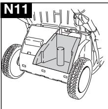
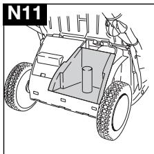
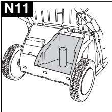
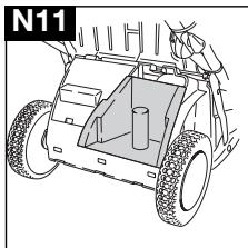
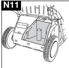
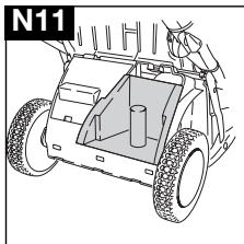
- Ensure mulching plug is securely fitted. (N11)
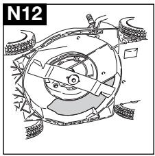
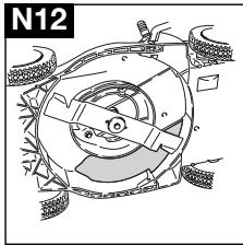
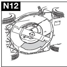
- The mulching plug prevents grass from being collected by blocking the collection chute on the underside of the deck. (N12)
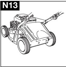
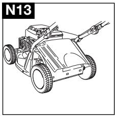
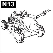
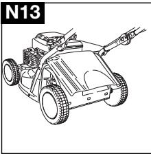
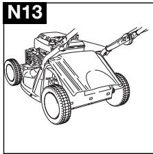
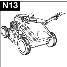
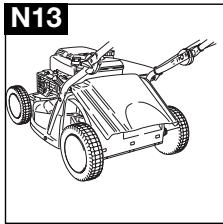
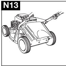
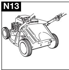
- Ensure the safety flap is positioned correctly. (N13)
N12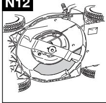
N6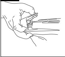
MAINTENANCE
IMPORTANT
Do not attempt any maintenance on your lawnmower when the engine is hot.
Cleaning
IMPORTANT
Never use water for cleaning your lawnmower. Do not clean with chemical, including petrol, or solvents - some can destroy critical plastic parts.
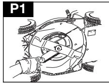
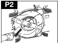
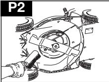
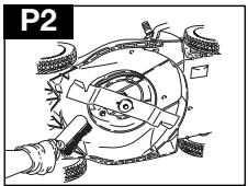
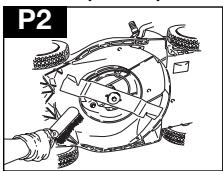
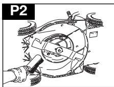
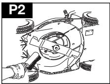
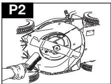
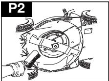
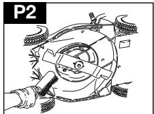
- Remove grass from under the deck with a brush (P1 and P2).
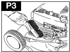
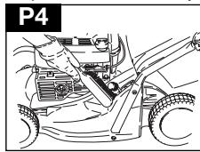
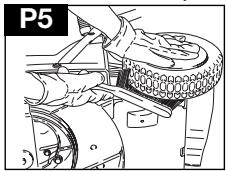
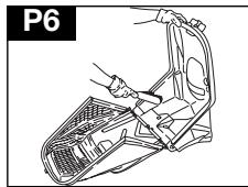
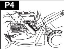
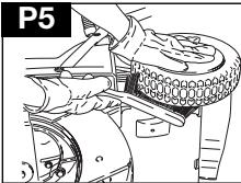
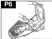
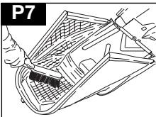
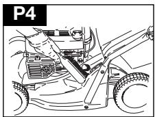
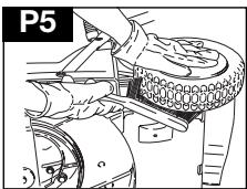
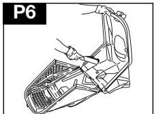
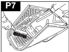
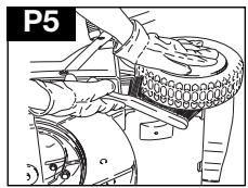
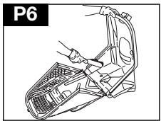
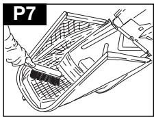
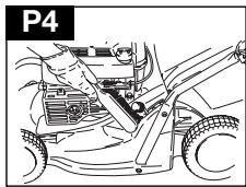
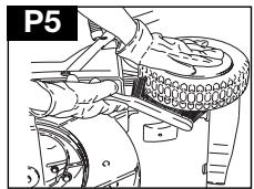
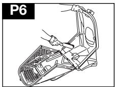
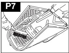
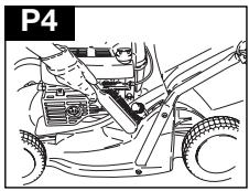
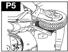
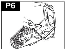
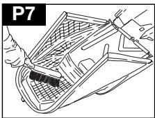
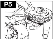
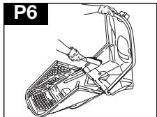
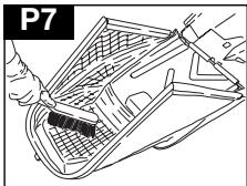
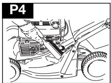
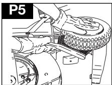
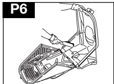
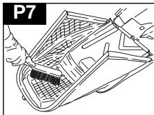
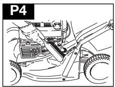
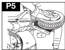
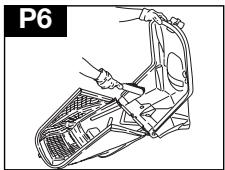
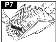
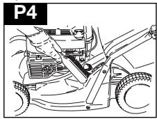
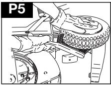
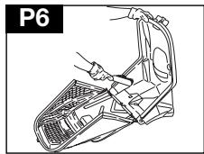
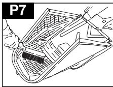
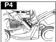
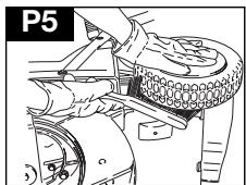
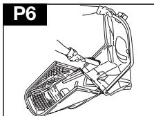
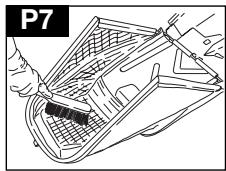
- Using a soft brush, remove grass clippings from the engine air intakes and exhaust (P3), cutting height adjustment area (P4), around the wheels (P5), and the grassbox (P6 & P7).
- Wipe over the surface of your lawnmower with a dry cloth.
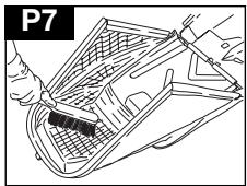
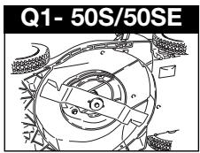
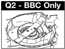
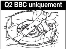
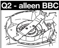
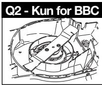
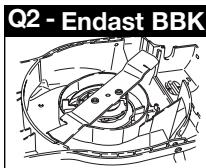
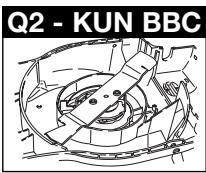
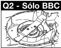
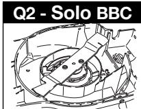
Cutting System: Removing the Blade (Q1 or Q2 BBC Only)
- Disconnect the spark plug lead.
- Use a spanner to loosen the blade bolt by turning anti-clockwise.
- Remove the blade bolt, blade, and spacer washer.
- Inspect for damage and clean as necessary.
Fitting the Blade
(Q1 or Q2 BBC Only)
- Fit the blade to the machine with the sharp edges pointing away from the machine.
- Re-assemble the blade bolt through the blade and spacer washer.
- Hold firmly and tighten the blade bolt firmly with a spanner. Do not over-tighten.
Please note:
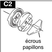
If you have a machine fitted with BBC, you must remove both blade bolts with a hexagonal drive key.
Always handle the blade with care - sharp edges could cause injury.
USE GLOVES
Renew your metal blade after 50 hours mowing or 2 years whichever is the sooner - regardless of condition. If the blade is cracked or damaged replace it with a new one.
How to Charge the Battery (50SE ONLY)
- Stop your lawnmower.
- Disconnect the spark plug.
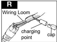
- Remove the cap from the charging point at the bottom of the wiring loom (R).
- Plug charger lead into connection on battery loom
- Plug the battery charger into a domestic electric socket.
- Charging will then commence.
- Charge for 24 hours.
- After charging, disconnect the charger from the socket and charging point.
- Replace the cap on the charging point.
- The unit is now ready for use.
- Stop your lawnmower.
- Disconnect the spark plug.
- Remove the cap from the charging point at the bottom of the wiring loom (R).
- Plug the charger lead into the connection on the battery loom.
- Plug the battery charger into a domestic electric socket.
- Charging will then commence.
- After charging, disconnect the charger from the socket and the charging point.
- Replace the cap on the charging point.
- The unit is now ready for use.
ENVIRONMENTAL INFORMATION
Electrolux Outdoor Products are manufactured under an Environmental Management System (ISO 14001) using, where practical, components manufactured in the most environmentally responsible manner, according to company procedures, and with the potential for recycling at the end of the products' life.
- Packaging is recyclable and plastic components have been labelled (where practical) for categorised recycling.
- Awareness of the environment must be considered when disposing of 'end-of-life' product.
- If necessary, contact your local authority for disposal information.
BATTERY DISPOSAL
- The battery should be taken to an Approved Service Centre or your local Recycling Station.
- Do NOT dispose of used battery with household waste
- Lead/Acid batteries can be harmful and should be disposed of through the recognised recycling facility in accordance with European Regulation
- Do NOT dispose of battery to water.
- Do NOT incinerate
DISPOSAL OF FUELS AND LUBRICATING OILS
- Wear protective clothing when handling any fuels and lubricants.
- Avoid contact with skin.
- Remove petrol and engine oil before transporting the product.
- Contact your local authority for information of your nearest Recycling/Disposal Station.
- Do NOT dispose of used fuels/oils with household waste
- Waste fuels/oils are harmful, but can be recycled and should be disposed of through the recognised facilities.
- Do NOT dispose of used fuels/oils to water.
- Do NOT incinerate
ENVIRONMENTAL INFORMATION
MAINTENANCE
Battery Replacement
- The battery is located underneath a cover behind the engine.
- Stop the lawnmower and disconnect the spark plug.
- Remove the screws from the cover.
- Remove cover to gain access to the battery.
IMPORTANT: Replacement batteries will need to be charged before use.
Ensure that neither the charger nor the battery are exposed to moisture.
The battery pack can be replaced by unclipping the battery from its housing and disconnecting the battery pack from the battery leads.
General Guidance on Rechargeable Battery
- Charging time is 24 hours.
- Under normal usage the battery will be charged during the running of the engine.
- To keep in prime condition the battery should be charged at least once every six months.
- Exceeding the charging period may shorten the battery life.
- Protect electric cable. Never carry the battery charger by the electric cable only.
- If after an extended usage period the battery quickly runs down after a full 24 hour charging period, a replacement battery is probably needed.
- Do not attempt to open the main body casing.
- Clean only with a dry soft cloth.
- Never use a damp cloth or flammable liquids such as petrol, white spirits, thinners etc.
- Dispose of old batteries safely.
The engine brake cable should always be adjusted to stop the engine within 3 sec. CAUTION! For adjustment contact your authorized service dealer.
At the End of the Mowing Season
- Replace blade, bolts, nuts or screws, if necessary.
- Clean your lawnmower thoroughly.
- Ask your local Service Centre to clean the air filter thoroughly and carry out any service or repairs required.
- Drain engine of oil and petrol.
Storing your Lawnmower
- Do not store your lawnmower immediately after use.
- Wait until the engine has cooled to avoid a potential fire hazard.
- Clean your lawnmower
- Store in a cool, dry place where your lawnmower is protected from damage.
Service Recommendations
We strongly recommend that your product is serviced at least every twelve months, more often in a professional application.
Engine Maintenance Schedule
Follow the hourly or calendar intervals, whichever occur first. More frequent service is required when operating in adverse conditions.
First 5 hours - Change oil.
Every 5 hours or daily - Check oil level. Clean finger guard. Clean around muffler.
Every 25 hours or every season - Change oil if operating under heavy load or high ambient temperature. Service air cleaner.
Every 50 hours or every season - Change oil. Inspect spark arrester, if equipped.
Every 100 hours or every season - Clean cooling system*. Replace spark plug.
* Clean more often under dusty conditions, or when airborne debris is present or after prolonged operation cutting tall, dry grass.
Engine Servicing & Guarantee
The engine fitted to your lawnmower is guaranteed by the Engine Manufacturer. To obtain further information contact your dealer.
Fault Finding
Engine Will Not Start
- Ensure OPC Lever /BBC arm is in the start position.
- Check that the control lever is in the '+' position
- Check that there is sufficient fuel in the tank and the cap air vent is clear.
- Remove and dry the spark plug.
- Petrol may be stale, replace. Once petrol has been replaced, it may take a little time for fresh petrol to filter through.
- Check that the blade bolt is tight. A loose bolt could cause difficult starting.
- If the engine will still not start, immediately disconnect the spark plug lead.
- CONSULT YOUR LOCAL APPROVED SERVICE CENTRE.
Engine Will Not Turn Over (50SE only)
- Ensure OPC Lever /BBC arm is in the start position.
- Battery flat - start your lawnmower manually.
- If the engine will still not turn over, immediately disconnect the spark plug lead.
- CONSULT YOUR LOCAL APPROVED SERVICE CENTRE.
Lack of Engine Power and/or Overheating
- Check that the control lever is in the 'normal' position.
- Disconnect the spark plug lead and allow the engine to cool down.
- Clean grass clippings and debris from around the engine and air inlets and the underside of the deck including the chute.
- Clean the engine air filter (ask your local Approved Service Centre to clean the engine air filter thoroughly).
- Petrol may be stale, replace. Once petrol has been replaced, it may take a little time for fresh petrol to filter through.
- If the engine still lacks power and/or is overheating, immediately disconnect the spark plug lead.
- CONSULT YOUR LOCAL APPROVED SERVICE CENTRE.
Excessive Vibration
- Disconnect the spark plug lead.
- Check that the blade is correctly fitted see page 7.
- If the blade is damaged or worn replace it with a new one.
- If vibration persists, immediately disconnect the spark plug lead.
- CONSULT YOUR LOCAL APPROVED SERVICE CENTRE.
C2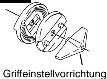
D2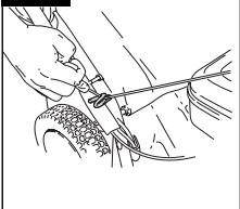
D3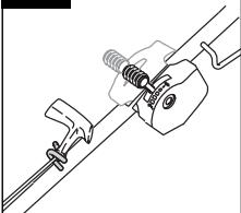
Benzin
Note:
MAINTENANCE
IMPORTANT
Cutting unit
Removing the blade
Q1 or Q2, only BBC
Q2 - Only BBC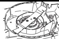
Note

Fuel
Shredding
MAINTENANCE
IMPORTANT
C2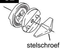
D2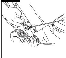
Fuel
Note:
Empty the grass catcher
MAINTENANCE
IMPORTANT
Cutting mechanism
Note
C2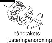
D2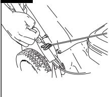
D3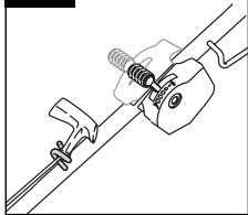
Gasoline
Brand:
Use of BioClip
MAINTENANCE
IMPORTANT
Cutting system
Removing the blade
Only Q1 or Q2 BBC
Note
Starter cord
- Disconnect the spark plug wire.
Gasoline
Note!
N2
N4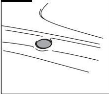
N6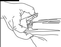
N8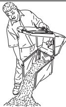
N9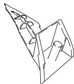
N11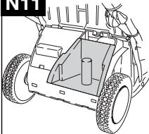
N12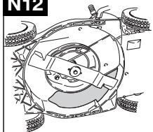
N13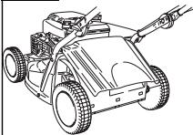
MAINTENANCE
Q2 - BBC MODELS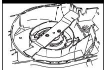
C2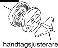
D2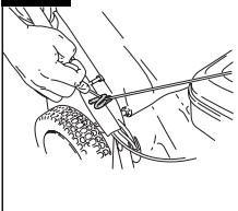
D3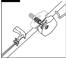
Petrol
Subsequent starts
Connection of
the drive - see
Royal 50S
Connection of the drive - see Royal 50S
N2
Note:
N4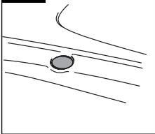
Draining of
grass collector
N6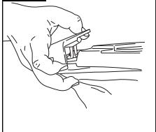
N13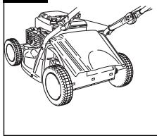
MAINTENANCE
IMPORTANT
Cutting system
Removal of the blade
Note
C2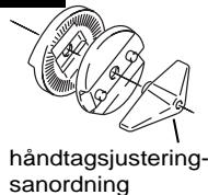
D2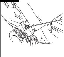
D3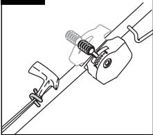
Gasoline
Starting and stopping the Royal 50SE Start
N2
N4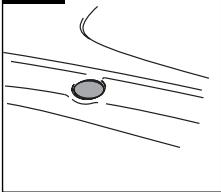
N7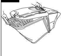
Use of bioprop
N12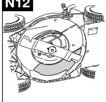
MAINTENANCE
IMPORTANT
Cutting system
Removing the blade
Only Q1 or Q2 BBC
Please note
D2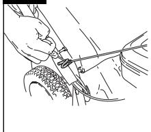
D3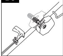
Gasoline
Starting and stopping the Royal 50SE
Starting

MAINTENANCE
IMPORTANT
C2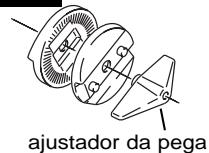
- Position the rope in the starter rope guide located on the lower handle. (D2)
- Position the rope in the starter rope guide located on the upper handle. (D3)
D2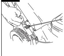
D3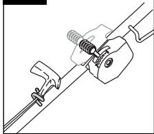
Gasoline
Rear Engine Start
Stop
- Release the engagement lever.
- Release the CPO lever.
Engagement -
See Royal 50S
N2
Note that:-
N4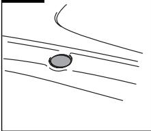
N6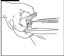
MAINTENANCE
IMPORTANT
Cutting System
Blade Removal
Q1 or Q2, BBC Only
Q2 - BBC Only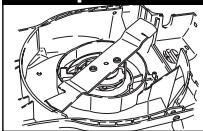
Note that:
C2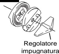
Gasoline
Note:
MAINTENANCE
IMPORTANT
- Wipe the surface of the lawn mower with a dry cloth.
Note:
Electrolux Outdoor Products
Aycliffe Industrial Park
NEWTON AYCLIFFE
Co. Durham DL5 6UP
ENGLAND
Telephone - (00) 44 1325 300303 Fax - (00) 44 1325 310339
UK Customer Helpline - 01325 300303 Fax - 01325 310339
Our policy of continuous improvement means that the specification of products may be altered from time to time without prior notice. Electrolux Outdoor Products manufacture products for a number of well known brands under various registered patents, designs and trademarks in several countries.
© Electrolux Outdoor Products Ltd. Registered Office, Electrolux Works, Oakley Road, Luton LU4 9QQ
Registered number 974979 England

From the Electrolux Group. The world's No.1 choice.
The Electrolux Group is the world's largest producer of powered appliances for kitchen, cleaning and outdoor use. More than 55 million Electrolux Group products (such as refrigerators, cookers, washing machines, vacuum cleaners, chain saws and lawn mowers) are sold each year to a value of approx. USD 14 billion in more than 150 countries around the world.

- ROYAL 50S
- ROYAL 50SE
- ROYAL 50S/BBC
- CE
- GB
- OPERATOR'S MANUAL
- D
- BETRIEBSANLEITUNG
- D - CONTENTS
- SAFETY PRECAUTIONS
- EXPLANATION OF SYMBOLS ON YOUR HUSQVARNA ROYAL 50S, 50SE & 50SBBC
- GENERAL
- FUEL SAFETY WARNING - PETROL IS HIGHLY FLAMMABLE
- SAFETY PROCEDURES WHEN CHARGING THE BATTERY (ROYAL 50SE)
- PREPARATION
- USE
- MAINTENANCE AND STORAGE
- PRODUCT RATING LABEL
- B
- ASSEMBLY INSTRUCTIONS
- HANDLE ASSEMBLY
- RECOIL STARTER
- FITTING THE GRASSBOX
- ENGINE NOTES
- OIL
- PETROL
- STARTING - PRIMING THE ENGINE
- STARTING THE ENGINE FOR THE FIRST TIME
- STARTING ENGINE THEREAFTER
- USE - STARTING AND STOPPING
- STARTING & STOPPING ROYAL 50S
- STARTING
- ENGAGING THE DRIVE
- STOPPING
- STARTING & STOPPING ROYAL 50SE
- ENGAGING THE DRIVE - SEE ROYAL 50S
- STARTING & STOPPING ROYAL 50S/BBC (BBC - BLADE, BRAKE, CLUTCH)
- PLEASE NOTE
- HOW TO MOW
- DO NOT OVERLOAD YOUR LAWNMOWER
- CUTTING HEIGHT
- ADJUSTMENT
- GRASS COLLECTION INDICATOR
- EMPTYING THE GRASSBOX
- USING AS A MULCHER
- MAINTENANCE
- IMPORTANT
- CLEANING
- CUTTING SYSTEM: REMOVING THE BLADE (Q1 OR Q2 BBC ONLY)
- FITTING THE BLADE
- (Q1 OR Q2 BBC ONLY)
- ALWAYS HANDLE THE BLADE WITH CARE - SHARP EDGES COULD CAUSE INJURY
- USE GLOVES
- HOW TO CHARGE THE BATTERY (50SE ONLY)
- ENVIRONMENTAL INFORMATION
- BATTERY DISPOSAL
- DISPOSAL OF FUELS AND LUBRICATING OILS
- BATTERY REPLACEMENT
- IMPORTANT: REPLACEMENT BATTERIES WILL NEED TO BE CHARGED BEFORE USE
- ENSURE THAT NEITHER THE CHARGER NOR THE BATTERY ARE EXPOSED TO MOISTURE
- THE BATTERY PACK CAN BE REPLACED BY UNCLIPPING THE BATTERY FROM ITS HOUSING AND DISCONNECTING THE BATTERY PACK FROM THE BATTERY LEADS
- GENERAL GUIDANCE ON RECHARGEABLE BATTERY
- THE ENGINE BRAKE CABLE SHOULD ALWAYS BE ADJUSTED TO STOP THE ENGINE WITHIN 3 SEC. CAUTION! FOR ADJUSTMENT CONTACT YOUR AUTHORIZED SERVICE DEALER
- AT THE END OF THE MOWING SEASON
- STORING YOUR LAWNMOWER
- SERVICE RECOMMENDATIONS
- ENGINE MAINTENANCE SCHEDULE
- ENGINE SERVICING & GUARANTEE
- FAULT FINDING
- ENGINE WILL NOT START
- ENGINE WILL NOT TURN OVER (50SE ONLY)
- LACK OF ENGINE POWER AND/OR OVERHEATING
- EXCESSIVE VIBRATION
- BENZIN
- NOTE
- CUTTING UNIT
- REMOVING THE BLADE
- FUEL
- SHREDDING
- EMPTY THE GRASS CATCHER
- CUTTING MECHANISM
- GASOLINE
- BRAND
- USE OF BIOCLIP
- CUTTING SYSTEM
- ONLY Q1 OR Q2 BBC
- STARTER CORD
- SUBSEQUENT STARTS
- CONNECTION OF
- THE DRIVE - SEE
- CONNECTION OF THE DRIVE - SEE ROYAL 50S
- DRAINING OF
- GRASS COLLECTOR
- REMOVAL OF THE BLADE
- STARTING AND STOPPING THE ROYAL 50SE START
- USE OF BIOPROP
- STARTING AND STOPPING THE ROYAL 50SE
- REAR ENGINE START
- STOP
- ENGAGEMENT
- SEE ROYAL 50S
- NOTE THAT
- BLADE REMOVAL
- Q1 OR Q2, BBC ONLY
- FROM THE ELECTROLUX GROUP. THE WORLD'S NO.1 CHOICE
Brand : HUSQVARNA
Model : ROYAL 50 S BBC
Category : Motorcycle