
FS 6600 D - Concrete saw HUSQVARNA - Free user manual and instructions
Find the device manual for free FS 6600 D HUSQVARNA in PDF.

User questions about FS 6600 D HUSQVARNA
0 question about this device. Answer the ones you know or ask your own.
Ask a new question about this device
Download the instructions for your Concrete saw in PDF format for free! Find your manual FS 6600 D - HUSQVARNA and take your electronic device back in hand. On this page are published all the documents necessary for the use of your device. FS 6600 D by HUSQVARNA.
USER MANUAL FS 6600 D HUSQVARNA
Please read the operator's manual carefully and make sure you understand the instructions before using the machine.

GB - EC DECLARATION OF CONFORMITY
Husqvarna AB, SE-433 81 Göteborg, Sweden, tel: +46-31-949000, declares under sole responsibility that the Husqvarna FS 6600 D, FS 8400 D dating from 2010 serial numbers and onwards (the year is clearly stated on the rating plate, followed by the serial number), complies with the requirements of the COUNCILIIS DIRECTIVE:
of May 17, 2006 "relating to machinery" 2006/42/EC
- of December 15, 2004 "relating to electromagnetic compatibility" 2004/108/EC.
- of May 8, 2000 "relating to the noise emissions in the environment" 2000/14/EC.
The following standards have been applied: EN ISO 12100:2003, EN 55014-1:2006, EN 55014-2/A1:2001, EN 61000-3-2:2006, EN 61000-3-3/A1/A2:2005, EN 13862/A1:2009.
Huskvarna December 29, 2009

Henric Andersson
Vice President, Head of Power Cutters and Construction Equipment
(Authorized representative for Husqvarna AB and responsible for technical documentation.)
FR - ASSURANCE DE CONFORMITE UE
Declaration of Conformity With The "Machines" Directive 2
Warnings, Do's and Do Not's. 8-9
Symbol Definitions 14-21
Warning, Poison Exhaust Gas, Hearing Hazard 22
Warning, Dust 23
Technical Data - Sound Level, EMC, and HAV. 24
Decals. 31-35
FS6600 Diesel Specifications Standard & CE 36
FS8400 Diesel Specifications Standard & CE 37
Special Instructions For Changing Blade Speed On Concrete / Asphalt Saws 42
Engine Speed / Blade Size 42 - 43
Engine Information / John Deere Warranty Registration 44
Pre Operation Checklist 45
Scheduled Maintenance Quick Reference 45
REFERENCE FIGURES
Figure 1 46
Figure 2 47
Figure 3-1 47
Figure 3-2 48
Figure 4 49
Figure 5 49
Figure 6 50
INSTRUCTIONS
- Uses 51
- Moving The Machine 51
- Transport (Blade Removed) 52
- Check Before Starting 52
- Fitting The Blade 52
- Starting The Saw 53
- Stopping The Saw 54
- Incidents During Sawing 54
- Adjustments: Straight Line Sawing 55
- Maintenance 55
- Blade Shaft V-Belt Tension 56
- Hydraulic System 56
- Important Advice 56
- Engine Speed Adjustment 57
- Accessories 58
- Large Diameter Models 58
- Repairs 59
- Spare Parts 59
FS6600 DIESEL BLADE SIZE CONVERSION CHART 92 - 93
FS8400 DIESEL BLADE SIZE CONVERSION CHART 94-95
BLADE SIZE CONVERSION: HUSQVARNA FS 6600 D / FS 8400 D, 3 SPEED GEARBOX MODELS.96 - 97
INDICE
Specifications FS6600 diesel standard & CE 40
Spécifications FS8400 diesel standard & CE 41
DO Read this entire operator's manual before operating this machine. Understand all warnings, instructions, and controls.
DO Read OM, FS6600D, FS6800D, FS9900D, LCD Display, Electronic Controls, Husqvarna, EN, 2009-12 available at http://us.husqvarnacp.com under service literature.
DO keep all guards in place and in good condition.
DO wear safety approved hearing, eye, head and respiratory protection.
DO read and understand all warnings and instructions on the machine.
DO read and understand the symbol definitions contained in this manual.
DO keep all parts of your body away from the blade and all other moving parts.
DO know how to stop the machine quickly in case of emergency.
DO shut off the engine and allow it to cool before refueling or doing maintenance.
DO inspect the blade, flanges and shafts for damage before installing the blade.
DO use the blade flange size shown for each blade size.
DO use only steel center diamond blades manufactured for use on concrete saws.
DO use only the blade flanges supplied with the saw. Never use damaged or worn blade flanges.
DO use only blades marked with a maximum operating speed greater than the blade shaft speed. Verify speed by checking blade shaft rpm and pulley diameters and blade flange diameters.
DO verify saw drive configuration by checking blade shaft RPM, pulley diameters, and blade flange diameter.
DO read all safety materials and instructions that accompany any blade used with this machine.
DO inspect each blade carefully before using it. If there are any signs of damage or unusual wear, DO NOT USE THE BLADE.
DO mount the blade solidly and firmly, Wrench tighten the arbor nut.
DO make sure the blade and flanges are clean and free of dirt and debris before mounting the blade on the saw.
DO use the correct blade for the type of work being done. Check with blade manufacturer if you do not know if blade is correct.
DO use caution and follow the instructions when loading and unloading the machine.
DO operate this machine only in well ventilated areas. Breathing Poison Exhaust Gas could result in death.
DO instruct bystanders on where to stand while the machine is in operation.
DO establish a training program for all operators of this machine.
DO clear the work area of unnecessary people. Never allow anyone to stand in front of or behind the blade while the engine is running.
DO make sure the blade is not contacting anything before starting the engine.
DO use caution when lifting and transporting this machine.
DO always tie down the machine when transporting.
DO use caution and follow instructions when setting up or transporting the machine.
DO have all service performed by competent service personnel
DO verify the blade arbor hole matches the machine spindle before mounting the blade.
DO always check for buried electrical cables before sawing. If unsure, contact the local utilities.
DO move the machine at least 10 feet (3 meters) from the fueling point before starting the engine and make sure the fuel cap is on the machine and properly tightened.
DO lift only from the lift bail.
DO clean the machine after each day's use.
DO use the proper blade flange size for each blade size. Never use damaged or worn blade flanges.
DO use caution when handling fuel.
DO only cut in a straight line.
DO only saw as deep as the job specifications require.
DO always give a copy of this manual to the equipment user. If you need extra copies, call TOLL FREE 1-800-288-5040 in USA, or for International, call +1-913-928-1300.
SAFETY FIRST!

WARNING DO'S AND DO NOT'S

WARNING: FAILURE TO COMPLY WITH THESE WARNINGS AND OPERATING INSTRUCTIONS COULD RESULT IN DEATH OR SERIOUS BODILY INJURY.
DO NOT
DO NOT operate this machine unless you have read and understood this operator's manual.
DO NOT operate this machine without the blade guard, or other protective guards in place.
DO NOT stand behind or in front of the blade path while the engine is running.
DO NOT leave this machine unattended while the engine is running.
DO NOT work on this machine while the engine is running.
DO NOT operate this machine when you are tired or fatigued.
DO NOT use a wet blade without adequate water supply to the blade.
DO NOT exceed maximum blade speed shown for each blade size. Excessive speed could result in blade breakage.
DO NOT operate the machine if you are uncertain of how to run the machine.
DO NOT use damaged equipment or blades.
DO NOT touch or try to stop a moving blade with your hand.
DO NOT cock, jam, wedge or twist the blade in a cut.
DO NOT transport a cutting machine with the blade mounted on the machine.
DO NOT use a blade that has been dropped or damaged
DO NOT use carbide tipped blades.
DO NOT touch a dry cutting diamond blade immediately after use. These blades require several minutes to cool after each cut.
DO NOT use damaged or worn blade flanges.
DO NOT allow other persons to be near the machine when starting, refueling, or when the machine is in operation.
DO NOT operate this machine in an enclosed area. Breathing Poison Exhaust Gas could result in death.
DO NOT operate this machine in the vicinity of anything that is flammable. Sparks could cause a fire or an explosion.
DO NOT allow blade exposure from the guard to be more than 180 degrees.
DO NOT operate this machine with the belt guards or blade guard removed.
DO NOT operate this machine unless you are specifically trained to do so.
DO NOT use a blade that has been over heated (Core has a bluish color).
DO NOT jam material into the blade.
DO NOT grind on the side of the blade.
DO NOT tow this machine behind a vehicle.
DO NOT use the tie down brackets for lifting this machine.
DO NOT operate this machine with the any guards or shields removed.
DO NOT cut deeper than 1" per pass with a dry blade. Step cut to achieve deeper cuts.
DO NOT operate this machine while using drugs or alcohol.
DO NOT engage bladeclutch with the engine RPM higher than 1200
This saw was designed for certain applications only. DO NOT modify this saw or use for any application other than for which it was designed. If you have any questions relative to its application, DO NOT use the saw until you have written Husqvarna Construction Products and we have advised you.
Husqvarna Construction Products North America
17400 West 119th Street
Olathe, Kansas 66061
USA

ADVERTENCIAS
Husqvarna Construction Products North America
17400 West 119th Street
Olathe, Kansas 66061
USA

CONSIGNES DE SECURITÉ
Husqvarna Construction Products North America
17400 West 119th Street
Olathe, Kansas 66061
USA

- This symbol indicates that the machine is in conformance with the applicable European directive.
- Este*simbolo indica que laquina es de conformidad con la directiva europea aplicable.
- Ce symbole indique que la machine est conforme à la directive européen applicable.

- Please read the instructions for use prior to operating the machine for the first time.
- Por favor lea las instrucciones de uso antes de manejar laquina por primera vez.
- Ne pas oublier de dire les instructions d'utilisation avant d'utiliser la machine pour la première fois.

- Mandatory
- Obligatorio
Obligatoire

- Indication
- Indicación
- Indication

Prohibition
- Prohibación
- Interdiction

-
Warning Triangle
Triángulo de advertencia
Triangle d'avertissement -
Wear Eye Protection
- Use proteccion para los ojos
- Porter une protection des yeux

Carbon monoxide (CO) has the distinction of being one of the few commonly encountered industrial gasses that is both highly toxic (poison) and odorless. When inhaled, CO acts as a chemical asphyxiant by preferentially combining with hemoglobin in the blood stream. As a result, the hemoglobin is not able to transport its normal amount of oxygen, which results in under-oxygenation of tissues. Symptoms of low-level CO exposure include headaches, dizziness, confusion, and nausea. However, loss of consciousness, permanent injury and death may result from continued or more intense exposure. Because of the health hazards associated with CO inhalation, the Occupational Safety and Health Administration (OSHA) have imposed personal exposure limits. The OSHA exposure limits, which are specified in the 29 CFR 1910.1000 (1998 Revision), allow for a 200 PPM Ceiling Limit and a TWA of 35 PPM per 8-hour shift/40-hr workweek. It is strongly recommended that the OSHA 29 CFR 1910.1000 (Code of Federal Regulations) be consulted for more information on exposure limits for various hazardous materials. If CO Poisoning is suspected immediately remove the victim to fresh air and obtain emergency medical attention.
Proper Ventilation:
THIS SAW IS SHIPPED FROM THE FACTORY WITHOUT A CATALYTIC CONVERTER. It is important to be aware that saws with catalytic converters reduce CO and hydrocarbon (HC) emissions. The exhaust still contains CO. If the workspace is too confined or under-ventilated, CO may accumulate until it eventually exceeds OSHA limits. When this happens, action must be taken to remove workers from areas of high concentration. Operators and work area supervisors should take precautions to insure adequate ventilation of the workspace at all times. Carbon monoxide detection monitors should be used to determine that adequate ventilation exists.

WARNING HEARING HAZARD
DURING NORMAL USE OF THIS MACHINE, OPERATOR MAY BE EXPOSED TO A NOISE LEVEL EQUAL TO 85 dB (A) OR GREATER. TEMPORARY AND/OR PERMANENT DAMAGE TO HEARING MAY RESULT. HEARING PROTECTION REQUIRED.

DUST WARNING

Cutting, especially when DRY cutting, generates dust that comes from the material being cut, which frequently contains silica. Silica is a basic component of sand, quartz, brick clay, granite and numerous other minerals and rocks. Exposure to excessive amount of such dust can cause:
- Respiratory diseases (affecting your ability to breath), including chronic bronchitis, silicosis and pulmonary fibrosis from exposure to silica. These diseases may be fatal;
Skin irritation and rash; and -
Cancer according to NTP and IARC
-
National Toxicology Program, International Agency for Research on Cancer
Take precautionary steps
- Avoid inhalation of and skin contact with dust, mist and fumes;
- Wet cut when feasible, to minimize dust;
- Wear and ensure that all bystanders wear appropriate respiratory protection such as dust masks designed to filter out microscopic particles. (See OSHA 29 CFR Part 1910.1200)
California Prop 65 Warning:
Use of this product can cause exposure to materials known to the State of California to cause cancer and/or birth defects or other reproductive harm.
CAUTION
DIESEL FUEL
Use Low Sulfur Diesel (0.05% or 500 ppm) or Ultra Low Sulfur Diesel (0.0015% or 15ppm)
Biodiesel While ≤ 5% blends (B5) are preferred, biodiesel concentrations up to a 20% blend (B20) in petroleum diesel fuel can be used in all John Deere engines. Biodiesel blends up to B20 can be used ONLY if the biodiesel (100% biodiesel or B100) meets ASTM D6751 (US), EN 14214 (EU), or equivalent specification. Expect a 2% reduction in power and a 3% reduction in fuel economy when using B20.
For additional information on Diesel Fuel and Bio Diesel, see http://us.husqvarnacp.com
Navigate to Service, then Service Literature, search for Diesel Fuel.
TECHNICAL DATA - Sound Level and HAV
FS 8400 D
| Noise emissions (see note 1) | |
| Sound power level, measured dB(A) | 116 |
| Sound power level, guaranteed dB(A) | 117 |
| Sound levels (see note 2) | |
| Sound pressure level at the operators ear, dB(A) | 96 |
| Vibration levels, a HV (see note 3) | |
| Handle right, m/s2 | 2,1 |
| Handle left, m/s2 | 2,0 |
Note 1: Noise emissions in the environment measured as sound power (L_WA) in conformity with EC directive 2000/14/EC.
Note 2: Noise pressure level according to EN 13862. Reported data for noise pressure level has a typical statistical dispersion (standard deviation) of 1.0dB(A)
Note 3: Vibration level according to EN 13862. Reported data for vibration level has a typical statistical dispersion (standard deviation) of 1m / s^2
FS 6600 D
| Noise emissions (see note 1) | |
| Sound power level, measured dB(A) | 114 |
| Sound power level, guaranteed dB(A) | 115 |
| Sound levels (see note 2) | |
| Sound pressure level at the operators ear, dB(A) | 96 |
| Vibration levels, ahv (see note 3) | |
| Handle right, m/s2 | 2,1 |
| Handle left, m/s2 | 2,0 |
Note 1: Noise emissions in the environment measured as sound power (L_WA) in conformity with EC directive 2000/14/EC.
Note 2: Noise pressure level according to EN 13862. Reported data for noise pressure level has a typical statistical dispersion (standard deviation) of 1.0dB(A)
Note 3: Vibration level according to EN 13862. Reported data for vibration level has a typical statistical dispersion (standard deviation) of 1m / s^2

ADVERTENCIA GASES DE ESCAPE VENENOSOS

3 Speed Gearbox Models With
4.5" (114mm) Diameter Flanges
522627702

GEARBOX RANGE / BLADE RPM (18-30)
TOP OF INSTRUMENT PANEL,
3 Speed Gearbox Models With
5.0" (127mm) Diameter Flanges
522627703
GEARBOX RANGE / BLADE RPM (20-36)
TOP OF INSTRUMENT PANEL,
3 Speed Gearbox Models With
6.0" (152mm) Diameter Flanges
522627704
3 Speed Gearbox Models With
7.0" (178mm) Diameter Flanges
522627705
3 Speed Gearbox Models With
8.0" (203mm) Diameter Flanges
522627706
3 Speed Gearbox Models With
8.0" (203mm) Diameter Flanges
522627707

DECALS & LOCATIONS ETIQUETAS Y SU UBICACION AUTOCOLLANTS ET LEURS EMPLACEMENTS
OPERATING INSTRUCTIONS
TOP OF COWL
521970301 Standard
521970302 CE version
OPERATING INSTRUCTIONS
INSTRUMENT PANEL
521921501

BLADE ROTATION DIRECTION
TOP OF BLADE GUARD
542 16 72-89*
WARNING:
1) Rear of Cowl above opening to transmission, Top of Frame
2) Both Sides of Engine by Lift Bail Mount
3) Front top of Frame, Below Right Angle Gear Box 542 17 62-23* (x4)

DIESEL FUEL DECAL
TOP LEFT OF COWL
525606001
DEPTH INDICATOR, TOP
542 19 97-13 Standard
504 63 01-01 CE Version
DEPTH INDICATOR
542 19 97-14 Standard
504 62 84-01 CE Version

Husqvarna
HUSQVARNA DECAL, 250mm Long
REAR OF COWL
542 19 07-33*

Husqvarna
FS6600D
HUSQVARNA FS 8400 D DECAL
SIDES OF COWL (FS 6600 D ONLY)
542 19 07-02 (2X)

Husqvarna
FS 8400D
HUSQVARNA FS 8400 D DECAL
SIDES OF COWL (FS 8400 D ONLY)
542 19 07-01 (2X)
EASY TRACK
TOP OF INSTRUMENT PANEL
542 19 94-33

TRANSMISSION BYPASS VALVE
FRAME - NEAR VALVE
542 19 06-28
- NOTE: Part No's. in the manual that have an
ASTERISK (*) suffix may not be active 9-digit numbers.
The '542' prefix has been added temporarily to current
6-digit part numbers and '0' to 8-digit part numbers.

HUSQVARNA CROWN “H” DECAL
FRONT OF HOOD (LATER FS 6600 D MODELS)
542 19 07-35
DECALS & LOCATIONS
MANUAL AXLE ADJUSTMENT
REAR OF COWL
542 19 94-35
WARNING
DO NOT CHANGE TO A LARGER BLADE GUARD SIZE WITHOUT CHANGING TO PROPER BELT DRIVE, ENGINE SPEED AND BLADE FLANGES. FAILURE TO COMPLY COULD RESULT IN DEATH OR SERIOUS BODILY INJURY. SEE OPERATOR'S MANUAL FOR INSTRUCTIONS. IF YOU DO NOT HAVE AN OPERATOR'S MANUAL CALL TOLL FREE 1-800-288-5040
BLADE GUARD WARNING, TOP OF BLADE GUARD
542 04 61-28*
WARNING

DO NOT Use A Larger Size Blade
Guard Without Changing To The Correct Belt Drive!
Benutzen Sie keinen
abweichenden
May Cause Burns And / Or
Ignition Of Material.
Avoid Contact!
MUFFLER HOT,
Front Side of Muffler Brace
Right Side Top of Fan Shield
542 16 90-65* (x2)
DECALS & LOCATIONS ETIQUETAS Y SU UBICACION AUTOCOLLANTS ET LEURS EMPLACEMENTS
| ENGINE SPEED / BLADE SIZE | |||||
| BLADE SIZE | FLANGE SIZE | BLADE SHAFT | JD ENGINE SPEED | ||
| LOADED RPM | PULLEY SIZE | RATED RPM | PULLEY SIZE | ||
| 18" | 5" | 2400 | 4.12" | 2800 | 4.75" |
| 26" | 5" | 1800 | 4.75" | 2800 | 4.12" |
| 30" | 5" | 1600 | 4.75" | 2800 | 3.65" |
| 36" | 6" | 1350 | 5.60" | 2800 | 3.65" |
| 48" | 8" | 1080 | 6.9" | 2800 | 3.65" |
| 60" | 10" | 810 | 9.3" | 2800 | 3.65" |
FS 8400 BLADESPEED CHART (1 SPEED MODELS)
TOP OF INSTRUMENT PANEL
525606002 Standard
542 19 95-86 CE version
| n min | n min | |||||
| 450 mm | 127 mm | 105 mm | 2400 | 600 - 850 mm | 121 mm | 2800 |
| 650 mm | 127 mm | 120 mm | 1800 | 600 - 650 mm | 105 mm | 2800 |
| 750 mm | 127 mm | 120 mm | 1600 | 700 - 750 mm | 93 mm | 2800 |
| 900 mm | 152 mm | 142 mm | 1350 | 750 - 900 mm | 93 mm | 2800 |
| 1200 mm | 203 mm | 175 mm | 1080 | 1000 - 1200 mm | 93 mm | 2800 |
| 1500 mm | 250 mm | 235 mm | 810 | 1250 - 1500 mm | 93 mm | 2800 |

PATENTS 542 18 04-27*

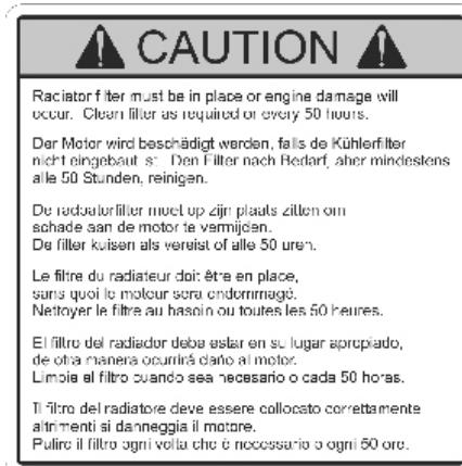
RADIATOR FILTER REAR COWLING
542 16 68-53 Standard 542 18 10-26 CE version

SOUND LEVEL - CE TOP OF BLADE GUARD 542 19 60-29*
- NOTE: Part No's. in the manual that have an ASTERISK (*) suffix may not be active 9-digit numbers. The '542' prefix has been added temporarily to current 6-digit part numbers and '0' to 8-digit part numbers.
FS6600 DIESEL SPECIFICATIONS
Standard & CE Models
| FS6600 Diesel Model | FS6600 20" | FS6600 26" | FS6600 30" | FS6600 36" | FS6600 42" | |
| FS6600 Diesel Model - CE | FS6600 450mm | FS6600 650mm | FS6600 750mm | FS6600 900mm | FS6600 1000mm | |
| ALL SAWS FEATURE: | ||||||
| Blade Guard Capacity - in. (mm) | 18 (457) | 26 (660) | 30 (762) | 36 (914) | 42 (1,067) | |
| Max. Depth of Cut - in. (mm) | 6,50 (165) | 10,50 (267) | 12,50 (318) | 15 (381) | 20,50 (508) | |
| Blade Shaft RPM | 2,400 | 1,800 | 1,600 | 1,350 | 1,180 | |
| Approximate Blade Shaft HP | 60 Horsepower | |||||
| Arbor Size in. (mm) | 1" (25.4) with single drive pin | |||||
| Quick Disconnect Blade Flange | 5 | 5 | 5 | 6 | 7 | |
| Diameter - in. (mm) | (127) | (127) | (127) | (152) | (178) | |
| Blade Shaft Diameter - in. (mm) | 2" (51) | |||||
| Blade Shaft Bearings | Cast Sealed blade shaft with 4 maintenance-free ball bearings | |||||
| Blade Shaft Drive | Dual 8-groove banded 3VX V-belts (16 grooves total) | |||||
| Blade Coolant | Zinc plated dual multiple-jet water spray tubes | |||||
| Blade Guard Attachment | Slip-on through 36" (900mm); Bolt-On for 42" (1000mm), auto-latch | |||||
| Blade Control | Electro-hydraulic pump raises blade; switch controlled raise/lower on speed control handle; switch controlled positive depth stop; dial type cutting depth indicator; blade drive disengagement system (clutch); quick disconnect blade flanges | |||||
| Axle | Front | 1.25" (31.75 mm) diameter | ||||
| Rear | Easy Adjust Center Pivot w/2 Hydraulic Powered Wheel Motors | |||||
| Wheels | Front | 8" x 3" x 1" (203mm x 76mm x 25.4mm) | ||||
| Rear | Thick polyurethane tread; sealed ball bearing requiring less maintenance | |||||
| 10" x 3" x 1.25" (254mm x 76mm x 32mm) | ||||||
| Solid rubber, Quick disconnect | ||||||
| Transmission | Hydrostatic Pump, w/2 Hydraulic Wheel Motors connected with hoses, neutral start switch, single handle speed control, Hydraulic bypass valve for pushing. | |||||
| Max. Ground Speed | Infinitely variable: 0 - 300 FPM forward & reverse. (25 M/min maximum reverse speed on CE models) | |||||
| Chassis | Heavy-duty, rigid, box and channel section construction | |||||
| Weight - lb. (Kg) - Uncrated | 1,789 (812) | 1,811 (822) | 1,832 (831) | 1,863 (845) | 1,888 (857) | |
| POWER SOURCE: | ||||||
| Engine | John Deere Turbocharged Charge Air Cooled Electronic Diesel | |||||
| Specifications | 4024HF295 EPA Tier 3/ Interim Tier 4, Euro Stage 3A Compliant | |||||
| Max. Horsepower | 66 @ 2,800 RPM DIN. (49.2 kW) | |||||
| Displacement cu. in. (l) | 149 cu. in. (2.44 liter) | |||||
| Bore - in. (mm) | 3.39 (86) | |||||
| Stroke - in. (mm) | 4.13 (105) | |||||
| Cylinders | 4 | |||||
| Fuel Capacity - gal. (l) | 10 (37.8) | |||||
| Oil Capacity - qt. (l) | 8.5 (8) with filter OR 7.6 (7.2) without filter | |||||
| Air Filter | Radial Seal with pre-cleaner and restriction indicator | |||||
| Starter | Electric | |||||
| Engine Coolant | 50/50 Water/Ethyl Glycol Mix | |||||
| SAW DIMENSIONS w/ 36" (900mm) guard: | Metric (mm) Inches | |||||
| A | Saw Width | 37-3/8 | 949 | |||
| B | Center to Center Wheel Width (track) - FRONT | 24-5/8 | 625 | |||
| Center to Center Wheel Width (track) - REAR | 25-1/4 | 642 | ||||
| C | Outside to Outside Wheel Width - FRONT | 27-5/8 | 702 | |||
| Outside to Outside Wheel Width - REAR | 28-1/4 | 717 | ||||
| D | Frame Width | 29-1/2 | 749 | |||
| E | Inner Flange to Inner Flange Width | 32-1/2 | 825 | |||
| F | Handle Extension | 30 | 762 | |||
| G | Minimum Saw Length (handles in, pointer up, guard up) | 61 | 1,550 | |||
| H | Saw Length (pointer up, handles extended) | 84 | 2,133 | |||
| I | Maximum Overall Height (pointer up) | 53 | 1,346 | |||
| Maximum Overall Height (top of pre-cleaner, pointer down) | 56 | 1,422 | ||||
| K | Minimum Overall Height (no muffler, rotate pre-cleaner) | 49-1/2 | 1,255 | |||
| L | Wheel Base | 24 | 610 | |||
| M | Guard to Handle Length (handles in) | 75 | 1,905 | |||
| N | Maximum Overall Length (handles in) | 106 1/2 | 2,705 | |||
| O | Maximum Overall Length (handles extended) | 129 | 3,276 | |||
FS8400 DIESEL SPECIFICATIONS
Standard & CE Models
| FS8400 Diesel Model | FS8400 20" | FS8400 26" | FS8400 30" | FS8400 36" | FS8400 42" | FS8400 48" | FS8400 60" | |
| FS8400 Diesel Model CE | FS8400 450mm | FS8400 600mm | FS8400 750mm | FS8400 900mm | FS8400 1050mm | FS8400 1200mm | FS8400 1500mm | |
| ALL SAWS FEATURE: | ||||||||
| Blade Guard Capacity - in. (mm) | 18 (457) | 26 (660) | 30 (762) | 36 (914) | 42 (1,067) | 48 (1,219) | 60 (1,524) | |
| Max. Depth of Cut - in. (mm) | 6.50 (165) | 10.50 (267) | 12.50 (318) | 15 (381) | 17.50 (508) | 20.50 (508) | 25 (635) | |
| Blade Shaft RPM | 2,400 | 1,800 | 1,600 | 1,350 | 1,180 | 1,080 | 815 | |
| Approximate Blade Shaft HP | 72 Horsepower | |||||||
| Arbor Size - in. (mm) | 1" (25.4) with single drive pin up to 48" blade; 1" (25.4) with 6 bolt BHP on 60" blade | |||||||
| Quick Disconnect Blade Flange | 5 | 5 | 5 | 6 | 7 | 8 | 10 | |
| Diameter - in. (mm) | (127) | (127) | (127) | (152) | (178) | (205) | (254) | |
| Blade Shaft Diameter - in. (mm) | 2" (51) | |||||||
| Blade Shaft Bearings | Cast Sealed blade shaft with 4 maintenance-free ball bearings | |||||||
| Blade Shaft Drive | Dual 10-groove banded 3VX V-belts (20 grooves total) | |||||||
| Blade Coolant | Zinc plated dual multiple-jet water spray tubes | |||||||
| Blade Guard Attachment | Slip-on through 36"; Bolt-on for 42" - 60", auto-latch | |||||||
| Blade Control | Electro-hydraulic pump raises blade; switch controlled raise/lower on speed control handle; switch controlled positive depth stop; dial type cutting depth indicator; blade drive disengagement system (clutch); quick disconnect blade flanges | |||||||
| Axle | Front | 1.25" (31.75 mm) diameter | ||||||
| Rear | Easy Adjust Center Pivot w/2 Hydraulic Powered Wheel Motors | |||||||
| Wheels | Front | 8" x 3" x 1" (203mm x 76mm x 25.4mm) Thick polyurethane tread; sealed ball bearing requiring less maintenance | ||||||
| Rear | 10" x 3" x 1.25" (254mm x 76mm x 32mm) Solid rubber, Quick disconnect | |||||||
| Transmission | Hydrostatic Pump, w/2 Hydraulic Wheel Motors connected with hoses, neutral start switch, single handle speed control, Hydraulic bypass valve for pushing. | |||||||
| Max. Ground Speed | Infinitely variable: 0 - 300 FPM forward & reverse. (25 M/min maximum Reverse Speed on CE models) | |||||||
| Chassis | Heavy-duty, rigid, box and channel section construction | |||||||
| Weight - lb. (Kg) - Uncrated | 1,890 (858) | 1,910 (867) | 1,930 (876) | 1,960 (890) | 1,990 (903) | 2,050 (930) | 2,300 (1044) | |
| POWER SOURCE: | ||||||||
| Engine | John Deere Turbocharged Charge Air Cooled Electronic Diesel | |||||||
| Specifications | 5030HF285 EPA Tier 3 Euro Stage 3A Compliant | |||||||
| Max. Horsepower | 82.5 @ 2,800 RPM DIN. (61.5 kW) | |||||||
| Displacement cu. in. (l) | 183 cu. in. (3 liter) | |||||||
| Bore / Stroke- in. (mm) | 3.39 (86) / 4.13 (105) | |||||||
| Cylinders / Stroke | 5 / 4 | |||||||
| Fuel Capacity - gal. (l.) | 9.75 (37) | |||||||
| Oil Capacity - qt. (l) | 11.8 (11.2) with filter OR 10.9 (10.6) without filter | |||||||
| Air Filter | Radial Seal with pre-cleaner and restriction indicator | |||||||
| Starter | Electric | |||||||
| Engine Coolant | 50/50 Water / Ethyl Glycol Mix | |||||||
| SAW DIMENSIONS w/ 36" guard: | ||||||||
| *Add about 8" (200mm) to Length for 60" (1500mm) | Metric | |||||||
| model. | Inches | mm | ||||||
| A | Saw Width | 37-3/8 | 949 | |||||
| B | Center to Center Wheel Width (track) - FRONT | 24-5/8 | 625 | |||||
| Center to Center Wheel Width (track) - REAR | 25-1/4 | 642 | ||||||
| C | Outside to Outside Wheel Width - FRONT | 27-1/4 | 692 | |||||
| Outside to Outside Wheel Width - REAR | 28-3/8 | 699 | ||||||
| D | Frame Width | 29-1/2 | 749 | |||||
| E | Inner Flange to Inner Flange Width | 32-1/2 | 826 | |||||
| F | Handle Extension | 28-1/2 | 724 | |||||
| G | Min. Saw *Length (handles in, pointer & guard up) | 71-1/2 | 1,816 | |||||
| H | Saw *Length (pointer down, handles out) | 141-1/2 | 3,594 | |||||
| I | Maximum Overall Height (pointer up) | 53 | 1,346 | |||||
| Max Overall Height (top of pre-cleaner, pointer down) | 64-1/2 | 1,632 | ||||||
| K | Min. Overall Height (no muffler, rotate pre-cleaner) | 49-1/2 | 1,255 | |||||
| L | Wheel Base Length | 27-3/4 | 705 | |||||
| M | Guard to Handle Length (handles in) | 75 | 1,905 | |||||
| N | Maximum Overall *Length (handles in) | 106 1/2 | 2,705 | |||||
| O | Maximum Overall *Length (handles extended) | 129 | 3,276 | |||||
Do not exceed blade shaft speed shown for each blade size. Excessive blade speed could result in blade breakage and serious personal injury.
As shown on the chart, some blade guards accept more than one size blade.
The FS 6600 saw is equipped with a John Deere 4024HF295 4-cylinder Tier 3/Interim Tier 4 EPA Compliant Diesel Engine.
The FS 8400 saw is equipped with a John Deere 5030HF285 5-cylinder Tier 3 EPA compliant Diesel Engine.
Upon receipt of your Saw, it is vitally important to register your engine with John Deere in order to receive a full warranty. Upon registering your engine, you will be ensuring that your John Deere servicing dealer network will be better prepared to meet all of your needs. Please take a few minutes to complete the online warranty registration.
The best way to register is to go online to www.JOHNDEERE.COM/ENGINEWARRANTY
The link to the online warranty registration opens in a second browser window (.]oup window). If you have installed a popup filter, you may not have access to the warranty registration. To view the warranty registration, please disable the popup filter.
INFORMACION DEL MOTOR
Engine Serial Number from Engine Serial Number Plate
(Recuired number is made up of two letters then four digits than one letter then six digits.
All 13 characters required.)
Date Engine Delivered
(Day) (Month) (Year)
Engine is
Original
Replacement
Equipment Manufacturer
Equipment Description & Model
(The equipment, not the engine.)
(What is? What does the manufacturer call it?)
Does the engine provide the power to move the equipment from place to place?
Yes
No
How will the equipment be used?
The John Deere Operation and Maintenance Manual for the above engine was received. The warranty, safe operation, and proper servicing of the engine were explained to me. I have received and have read the Engine Owner's Warranty.
leephore (
E-mail Address
Purchaser's Signature
Date
Note: Reglster via Internet at www.johndeere.com/enginewarranty or this form may be faxed to John Deere at 1-319-292-5644.
For information on your rights to privacy, please see page 2 of the John Deere Engine Owner's Warranty - Worldwide.
Before leaving our factory, every machine is thoroughly tested. Follow our instructions strictly and your machine will give you long service in normal operating conditions.

Before starting up the machine, make sure you read these entire Operating Instructions and are familiar with the operation of the machine. Read also Electronic Display Control Manual P/N 115159727. Manual can be found online at www.US.Husqvarna.com . Navigate to service. Check
box for Operators Manuals. Enter FS6600 in the Search Box Enter and select the correct manual.

MACHINE SET-UP:
ALWAYS park machine on a level surface with the engine "OFF" and the ignition switch set in the "0" (OFF) position before performing any maintenance. Let the machine cool down!!
- Check engine oil. Fill to the full mark on dip stick with 15W40 class CE or CD oil.
- Connect battery cables.
ALWAYS park machine on a level surface with the engine "OFF" and the ignition switch set in the "0" (OFF) position before performing any maintenance. Let the machine cool down!!
- Check the engine air cleaner hose clamps. Tighten as required.
- Tension the blade drive V-belts. DO NOT over tension!!
SCHEDULED MAINTENANCE QUICK REFERENCE

Before performing any maintenance, ALWAYS park the machine on a level surface with the engine "OFF" and the ignition switch set in the "OFF" position. Let the machine cool down!!
SERVICE DAILY:
- Check engine oil level.
- Check blade guard for damage.
- Check hoses and clamps for damage or looseness. Tighten or replace as necessary.
- Check air cleaner restriction indicator. Replace primary air filter if indicator is red.
- Make sure all safety guards are in place and in good condition.
- Check drive V-Belts Tension as Needed.
SERVICE EVERY 50 HOURS:
- Clean Rear shield Air filter.
- Inspect Radiator Air Filter and clean as necessary.
- Check blade drive V-belt tension. Tension both sides evenly. DO NOT over tension!!!
- Lubricate front wheel bearings.
- Replace Hydraulic System Filter. (First 50 hours only.)
SERVICE EVERY 100 HOURS:
- Replace engine oil and filter.
- Lubricate front axle pivot bearings.
- Check wheels for wear or damage.
- Check rear wheel hubs and wheels for looseness.
- Check engine air cleaner hose and clamps.
- Check hydraulic system fluid level.
SERVICE EVERY 250 HOURS:
- Replace Hydraulic System Filter
- Grease Blade Shaft 2 pumps each end.
SERVICE EVERY 500 HOURS:
- Replace Engine gearbox fluid.
- Replace hydraulic system fluid.
- Replace engine fuel filter (spin-on type).
SERVICE YEARLY:
- Replace air filter primary and safety element.
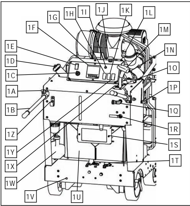
FIGURE 1
1A. KNOB: Use to tighten operators grip handles.
1B. HANDLE BARS: For operator gripping.
1C. ENGINE START SWITCH: Start and stop the engine with this switch.
1D. FUEL TANK FILL: Fill the fuel tank at this location.
1E. ENGINE THROTTLE: Controls engine RPM.
1F. CONSOLE DISPLAY: Displays engine rpm, water temperature, engine hours, oil pressure, oil temperature, voltage, fault codes.
WARNING: Take Notice of BLADE RPM Tachometer Top RH gauge Blade Tachometer indicate Blade Speed. Serious injury can occur to the operator or people in the work area if the rotational speed (n/min) of the DIAMOND BLADE (2E) exceeds the maximum speed (n/min) marked on the DIAMOND BLADE (2E).
1G. AXLE ADJUSTMENT SWITCH: Toggle switch to adjust rear drive axle. Push switch right to make saw drive to the right. Left to make saw drive to the left.
1H. WATER SAFETY SWITCH: Stops the engine if the water supply to the blade is interrupted. Set to activate switch.
11. LOW FUEL LEVEL: Lights up when fuel level is low. Add Low Sulfur #2 Diesel Fuel only.
1J. RED PALM SWITCH: For EMERGENCY STOP of saw. Stops all systems except lights, pull OUT to reset. Do not use for routine stopping.
1K. BLADE DEPTH STOP: Activates or overrides the depth stop for repetitive cuts at the same depth.
1L. AIR RESTRICTION INDICATOR: Service air filter elements when indicator shows a red mark. Reset before starting engine.
1M. SPEED CONTROL LEVER: Controls forward and reverse directions, stop, and the speed of the saw.
1N. RAISE/LOWER SWITCH: Located on speed control lever. Use to raise and lower the saw. Push up to raise saw upward. Push down to lower the saw.
10. BLADE DEPTH INDICATOR: Displays cutting depth. Sets cutting depth for BLADE DEPTH STOP.
1P. HANDLE ADJUSTMENT LOCK: Turn Clockwise to lock handle bar in position. Turn Counterclockwise to unlock and reposition handlebar.
1Q. WATER INLET: Connects to 3 14 ” garden hose for fresh water supply.
1R. WATER VALVE: Controls water flow rate to cool the blade.
1S. FUEL COOLER: Cools returned fuel.
1T. SAW LOWERING SPEED CONTROL KNOB: Turn knob clockwise to slow lowering speed. Turn knob counterclockwise to increase lowering speed.\n\n
1U. RADIATOR AIR FILTER ELEMENT
1V. MANUAL AXLE ADJUSTMENT: Turn bolt to adjust rear drive axle. Rotating it to the right (CW) makes saw drive to the right. Left (CCW) makes saw drive to the left.
1W. RADIATOR COOLANT OVERFLOW BOTTLE: Recovers radiator coolant when engine is hot. Should be 14 full when engine is off and cool.
1X. STOP POSITION: The saw will stop travel movement when the speed control lever (1M) is in this position. The engine will not start unless the Speed Control Lever (1M) is in the STOP position.
1Y. BLADE CLUTCH SWITCH: Engages Blades Drive Light indicates Clutch Engaged. Engage only with engine RPM at 1200 RPM or less.
1Z. HOSE HANGER: Supports water supply hose.
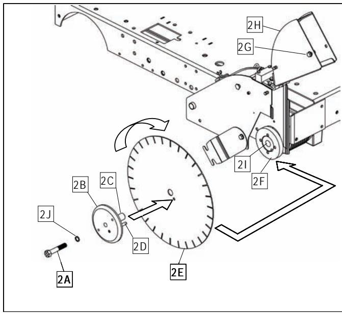
FIGURE 2
2A. BLADE SHAFT BOLT: Use to clamp the diamond blade between the inner and outer flange. Right side of saw has left hand threads. Left side of saw has right hand threads.
2B. OUTER FLANGE: Use to hold the diamond blade in position.
2C. OUTER FLANGE ARBOR: Use to support the diamond blade.
2D. LOCKING PIN: Use to prevent the diamond blade from rotating on the shaft during operation.
2E. DIAMOND BLADE: Use as the cutting tool for concrete and asphalt surfaces.
2F. INNER FLANGE: Inside support used to hold the diamond blade in position.
2G. BLADE GUARD NOSE LATCH: Use to latch the front part of blade guard down.
2H. BLADE GUARD FRONT: The front part of the blade guard.
21. BLADESHAFT: Supports Blade Flanges and blade.
2J. LOCK WASHER: Prevents Bladeshaft Bolt from loosening.
FIGURE 3-1
3-1A. ENGINE GEARBOX: Single Speed Model.
3-1B. WATER CONNECTION: Circulates freshwater through gearbox to cool it. Water then flows to the bladeguard.
3-1C. WATER DRAIN VALVE: To drain water from gearbox: Turn Counterclockwise to open, Clockwise to close. Drain daily to prevent corrosion or damage due to freezing temperatures.
3-1D. HOOD LATCH: One latch secures hood in lowered position. US Model Operation: 1. Press HOOD LATCH (3-1D3/3-2D3) inward. 2. Raise hood until HOOD SUPPORT (6H) is engaged & supports hood. CE Model Operation: 1. Use tool to loosen Capscrew (3-1D1/3-2D1). 2. Pivot tube latch (3-1D2/3-2D2) downward. 3. Press HOOD LATCH (3-1D3/3-2D3) inward. 4. Raise hood until HOOD SUPPORT (6H) is engaged & supports hood.
3-1E. FLANGE COVER: Guards against FLANGE contact during operation. Always keep in place!
3-1F. BELT PROTECTOR SHIELD: Keep in place.
3-1G. BLADESHAFT TUBE ASSY: Sealed unit contains bladeshaft, bearings and shaft seals.
3-1H. TIEDOWN LUGS: Used to tie the saw down while transporting by vehicle. Not to be used to lift the saw.
3-11. ENGINE OIL DRAIN VALVE: Drains engine oil without use of tools.
3-1J. BELT TENSIONING BOLTS:
3-1K. HORIZONTAL CLAMPING BOLTS:
3-1L. BLADE SHAFT PULSEY:
3-1M.V-BELTS:Set of 4.
3-1N. GEARBOX PULLEY:
FIGURE 3-2
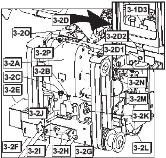
3-2A. ENGINE GEARBOX: Three Speed Model.
3-2B. WATER CONNECTION: Circulates freshwater through gearbox to cool it. Water then flows to the bladeguard.
3-2C. WATER DRAIN VALVE: To drain water from gearbox: Turn Counterclockwise to open, Clockwise to close. Drain daily to prevent corrosion or damage due to freezing temperatures.
3-2D. HOOD LATCH: One latch secures hood in lowered position. US Model Operation: 1. Press HOOD LATCH (3-1D3/3-2D3) inward. 2. Raise hood until HOOD SUPPORT (6H) is engaged & supports hood. CE Model Operation: 1. Use tool to loosen Capscrew (3-1D1/3-2D1). 2. Pivot tube latch (3-1D2/3-2D2) downward. 3. Press HOOD LATCH (3-1D3/3-2D3) inward. 4. Raise hood until HOOD SUPPORT (6H) is engaged & supports hood.
3-2E. FLANGE COVER: Guards against FLANGE contact during operation. Always keep in place!
3-2F. BELT PROTECTOR SHIELD: Keep in place.
3-2G. BLADESHAFT TUBE ASSY: Sealed unit contains bladeshaft, bearings and shaft seals.
3-2H. TIEDOWN LUGS: Used to tie the saw down while transporting by vehicle. Not to be used to lift the saw.
3-2I. ENGINE OIL DRAIN VALVE: Drains engine oil without use of tools.
3-2J. BELT TENSIONING BOLTS:
3-2K. HORIZONTAL CLAMPING BOLTS:
3-2L. BLADE SHAFT PULSEY:
3-2M.V-BELTS:Set of 4.
3-20. GEARBOX SHIFT LEVER: Use to change output speed of the ENGINE GEARBOX (3-2A). Three-Speeds and two Neutral positions are available. GEARBOX SHIFT LEVER positions (1, 2, and 3) are color coded to match, among others, Gearbox Range / Blade RPM decal. GEARBOX SHIFT LEVER Operation:
1) Turn ENGINE START SWITCH (1H) to OFF ("0") position. Always turn Engine OFF before shifting gearbox!
2) Verify that pulley size, flange size, and blade shaft speed are correct for the blade size being mounted.

WARNING: Serious injury can occur to the operator or people in the work area if the rotational speed (n/min) of the DIAMOND BLADE (2E) exceeds the maximum speed (n/min) marked on the DIAMOND BLADE (2E).
3) Lift GEARBOX DETENT KNOB (3-2P) and twist to hold in "OPEN" position.
4) Move GEARBOX SHIFT LEVER (3-2O) to required gear. A slight "rocking motion" of the gearbox output shaft (or BLADE SHAFT) may improve shifting.
5) Twist and lower GEARBOX DETENT KNOB (3-2P) back to original "LOCKED" position.
3-2P. GEARBOX DETENT KNOB: Locks GEARBOX SHIFT LEVER (3-2O) in position. See GEARBOX SHIFT LEVER (3-2O) for operation.
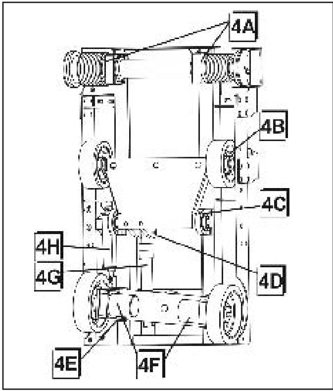
FIGURE 4
4A. BLADESHAFT BEARING SEALS
4B. FRONT WHEEL BEARINGS
4C. FRONT AXLE PIVOT BEARINGS
4D. HYDRAULIC CYLINDER PIVOT PIN
4E. REAR AXLE
4F. HYDRAULIC WHEEL MOTOR
4G. RAISE LOWER CYLINDER
4H. LINEAR ACTUATOR
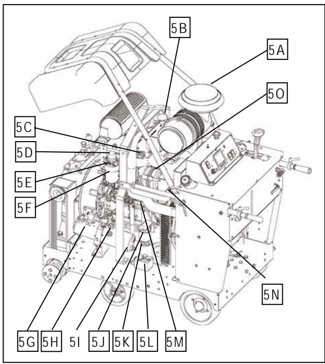
FIGURE 5
5A. AIR FILTER ASSEMBLY: Includes
a) Housing
b) Cover
c) Primary Outer Element: Clean or replace when restriction indicator shows the RED warning.
d) Inner Safety Element: DO NOT CLEAN this filter element. Replace 1 time per year or if it becomes damaged.
5B. RADIATOR COOLANT FILL: Fill radiator from this point. Replace cap if damaged.
5C. ENGINE OIL FILL: One of two fill points.
5D. FUEL HAND PRIMER PUMP: Push to prime fuel lines to help initial startup or as needed.
5E. FUEL BLEED VALVE: Open to bleed air from fuel lines.
5F. FUEL FILTER WATER SEPARATOR: See John Deere engine manual.
5G. D.C. (direct current) LIFT PUMP: Raises and lowers the saw.
5H. HYDRAULIC RESERVOIR FILL: Fill and check hydraulic system fluid here.
5I. HYDRAULIC RESERVOIR: 1.5 Quarts
5J. HYDRAULIC FILTER: Filters hydraulic system fluid.
5K. ENGINE OIL DRAIN HOSE: Connects to oil drain valve 3l. Use to drain engine oil.
5L. TRANSMISSION BYPASS VALVE: Turn counter clockwise to open. Turn clockwise to close. Open to push concrete saw.
5M. HYDROSTATIC TRANSMISSION PUMP.
5N. ALTERNATOR/WATERPUMP BELT: Self tensioning. See John Deere for replacements.
50. ALTERNATOR: See John Deere for replacements.
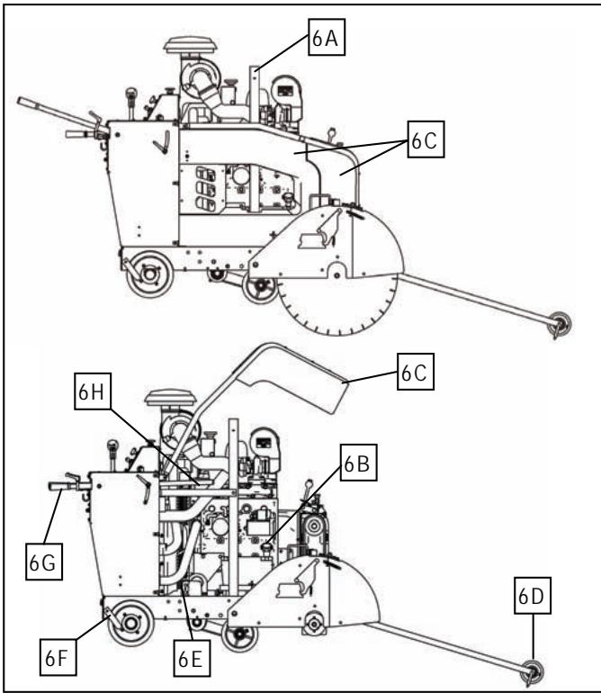
FIGURE 6
6A. LIFTING BALE: The saw can be lifted from this point.
6B. OIL LEVEL CHECK: Dipstick indicates oil level. Also an oil fill location.
6C. BELT GUARDS AND SHIELDS: Protects engine, guards, drives, and cooling fan.
6D. FRONT GUIDE: Use to locate the path of the diamond blade on the cutting line.

DO NOT OPERATE ENGINE WITH SHIELDS REMOVED!
6E. FAN SHIELDS: Protects engine, cooling fan, beltdrives and pulleys.
6F. REAR GUIDE: Use to locate the path of the diamond blade on the cutting line.
6G. HANDLEBARS: Used to maneuver the saw. Not to be used to lift the saw.
6H. ENGINE OIL FILTER: The Oil filter element needs to be changed when changing oil. (100 hr)
These signs will give advice for your safety
Before leaving our factory every machine is thoroughly tested.

Follow our instructions strictly and your machine will give you long service in normal operating conditions.
1. Uses
Use: Wet sawing of old and new concrete and asphalt. Dry sawing only with blade manufacturers approval of specific application.
Tools: Diamond blades — water cooled, Ø: 14", 18", 20", 24", 26", 30", 36", 42", 48" and 60" with Arbor Ø - 1". (For information, contact your Husqvarna supplier.)
Depths of Cut (Maximum):
| Blade | Depth | Blade | Depth |
| 14" | 4.5" | 350mm | 110mm |
| 18" | 6.5" | 450mm | 160mm |
| 20" | 7.5" | 500mm | 175mm |
| 24" | 9.5" | 600mm | 225mm |
| 26" | 10.5" | 650mm | 260mm |
| 30" | 12.5" | 750mm | 310mm |
| 36" | 15.0" | 900mm | 375mm |
| 42" | 17.5" | 1000mm | 410mm |
| 48" | 20.0" | 1200mm | 500mm |
| 60" | 25.0" | 1500mm | 620mm |

Before starting up the machine, make sure you read this entire manual and are familiar with the operation of this machine.

The working area must be completely clear, well lit and all safety hazards removed.


The operator must wear protective clothing appropriate to the work he is doing.


2. Moving The Machine
(See Figures 1, 2 and 5)
Set The Handles To The Desired Length:
- Loosen Knob (1A), pull the Handle Bar (1B) in or out to desired length, then tighten the Knob (1A). to adjust Handle Bar length, Turn Handle Bar Adjustment Lock (1P) counterclockwise to unlock. Adjust Handle Bar (1B) to the desired height. Turn Handle Adjustment Lock (1P), clockwise to lock in place.
Moving The Saw With The Engine Off:
- Turn Engine Start Switch (1C) to the “1” (RUN) position.
- Raise the saw by pressing up on the Toggle Switch (1N) on the Speed Control Lever (1M) until the Diamond Blade (2E) (if installed) clears the pavement surface.
- Put the Speed Control Lever (1M) into the STOP (1X) position.
- Set the Transmission Bypass valve (5L) counterclockwise to the up (NEUTRAL) position.
- The saw can now be moved by standing behind it and pushing [while holding the Handle Bars (1B)].

DO NOT attempt to push the saw while it is in NEUTRAL on a grade (or hill). The saw operator could lose control of the saw and cause injury to himself or other person(s) in the area.
Moving The Saw With Engine On:
- Raise the saw by pressing up on the toggle switch (1N). on Speed Control Lever (1M) until Diamond Blade (2E) (if installed) clears the pavement surface.
- Set the Water Safety Switch (1H) button to the "0" (OFF) position.
- Speed Control Lever (1M) must be in the STOP (1X) position to start the saw. The engine WILL NOT start unless the Speed Control Lever (1M) is in the STOP (1X) position.
- Check that the Transmission bypass valve (5L) is turned clockwise (DOWN) to the closed position. Do NOT start the engine if the valve (5L) is in the Neutral (OPEN) position.
- The Engine Throttle (1E) is at low idle speed setting.
- Set the Blade Clutch Switch (if installed) (1Y) to “0” (OFF).
-
·Turn the Engine Start Switch (1C) to the “1” (RUN) position. In COOL conditions the LCD Display (1F) will show the Message “ENGINE PREHEATING WAIT TO START” for 15 TO 30 seconds. The glow plugs warm the engine for smoke freecold weather starting.
-
When message clears, Turn the Engine Start Switch (1C) to the "2" (START) position until the engine starts, then release the switch. It will return to RUN position. If the engine does not start, turn keyswitch to "OFF" Position and repeat these steps.


- Push the Speed Control Lever (1M) forward for FORWARD saw movement, or to the rear for REVERSE saw movement. The further you push the lever the faster the speed.

DO NOT OPEN the bypass valve (5L) to neutral while the saw is parked on a grade (or hill), The Operator will lose control and injury or damage could occur.
3 Transport (Blade Removed)
(See Figures 1, 2, and 5)

Turn engine off. Set Speed Control Lever (1M) to STOP (1X) position. Remove diamond blade (2E) before transport.
When moving the saw up and down ramps, with engine on, use extreme caution.
- To go DOWN a ramp drive the saw FORWARD slowly.
- To go UP a ramp, back the saw in REVERSE slowly.

For steep ramps, always use a winch. Never stand below the machine.
Lifting The Saw. The saw can only be lifted by the factory installed Lifting Bail (6A).
To Transport By Vehicle:
- Set the Engine Start Switch (1C) in the OFF position.
- Set Speed Control Lever (1M) in the STOP (1X) position.
- Push Handle Bars (1B) inward and tighten Knobs (1A).

Block the saw in place or secure it into place using the factory installed TIE DOWN LUGS (3H), front and rear to prevent movement during transport.
4 Check Before Starting


Take into account the working conditions from health and safety point of view.
-
Fuel (Check the engine maintenance manual.) Use No. 2 Diesel Low Sulfur Fuel for normal conditions.
-
Check that the engine oil level is correct. Because the engine often operates at an angle, check the oil level (with engine horizontal) frequently to ensure that the oil level never falls below the lower mark on the dipstick. 15W40 CD or CE engine oil is recommended. (6B)
- For start up, refer to the engine manual. See John Deere Manual OMRG37673
5 Fitting The Blade
(See Figures 1 and 2)
- Set engine Start Switch (1C) to "1" position.
- Raise Machine to a high position using the raise/ lower switch (1N) on the Speed Control Lever (1M)
- Set the Engine Start Switch (1C) to the "0" (OFF) position.
- Loosen Bolt on Blade Guard Latch (2G).
- Raise Front Half of Blade Guard (2H)
- Loosen Bladeshaft Bolt (2A) Remove Outer Flange (2B) and Lock washer (2J).
- Fit Diamond Blade (2E) to Outer Flange Arbor (2C).
- Install Outer Flange (2B) into the Blade Shaft (2I) making sure that the Locking Pin (2D) passes through the Diamond Blade (2E) and into the Inner Flange (2F).
Note the direction of rotation of the blade. The direction of rotation is shown by an arrow on both the DIAMOND BLADE (2E) and the BLADE GUARD (2H). Make sure that the contact surfaces on the DIAMOND BLADE (2E), INNER & OUTER FLANGES (2B & 2F) and BLADE ARBOR (2C) are clean. Always use lockwasher(2J) with bladeshaft bolt (2A)
-
Rotate Outer Flange (2B) and Diamond Blade (2E) in the opposite direction of blade rotation to remove backlash.
-
Install and tighten Blade Shaft Bolt (2A) and Lock washer (2J) using the Blade Shaft Wrench while firmly holding the Diamond Blade (2E).
- Lower front half of Blade Guard (2H) and tighten the Bolt (2G) on the Blade Guard Latch (2G).
The Blade Shaft Bolt (2A) on the Right Hand side has Left Hand threads. The Blade Shaft Bolt (2A) on the Left Hand side has Right Hand threads. Always use Lockwasher (2J) with bladeshaft Bolt (2A) Replace Bolt (2A) and Lockwasher (2J) when worn or damaged.

Slip on blade guards are provided with a safety latch which engages the support spade and a bolt to retain the rear of the guard.

Do not operate this saw without the latch engaged and the bolt installed. Inspect blade guards and latches frequently. Do not use aged.
To Remove A SLIP-ON GUARD:
- Using the Blade Shaft Wrench remove the rear retaining bolt.
- Slip the Blade Shaft Wrench between the guard and the belt guard onto the latch lever. Raise the lever to unlatch and lift guard off spade.
To Install A SLIP-ON GUARD:
- Lower guard onto spade until latch engages.
- Install Bolt in rear of guard using the Blade Shaft Wrench.
6 Starting The Saw
(See Figures 1, 2 and 5)
Read and Understand Manual on Tier 3 Electronic Controls and Display Available online at http://us.husqvarnacp.com/. Navigate to service. Search for FS6600 FS8400 Display and Electronics Manual

Always pay extreme care and attention to the preparation of the machine before starting.

Remove all wrenches and tools from the floor and the machine.

Always keep blade guard, belt guards and fan guards in place.
- Follow all operating instructions and warnings in this manual and on the machine.
- Close the Water Valve (1R).
- Mark the surface to be cut by drawing a line where the cut is to be made.
- Pull out Handle Bars (1B) to desired length and tighten Knobs (1A).
- Lower the Front Guide (6D) and align the Front Guide (6D), Rear Guide (6F) and Diamond Blade (2E) with the line on the surface.
- To start the saw when no water pressure is present, set the Water Safety Switch (1G) to "0" (OFF).
- Set Speed Control Lever (1M) to the STOP (1X) position. Saw will not start unless the Speed Control Lever (1M) is in the STOP (1X) position. Check to be certain the Transmission Bypass Valve (5L) is closed in the down position.
- Set the Blade Clutch Switch (1Y) to "0" (OFF) (if equipped).
- Start the engine using the Engine Start Switch (1C). Follow the procedure in the engine manual. When message "Engine Preheating Wait To Start", is displayed, wait for the engine glow plugs to warm the engine. When message dissappears, Turn Switch (1C) to position 2 to start the engine.
-
Let the engine warm up for several minutes with Engine Throttle (1E) at the low speed setting.
-
When ready open the Water Valve (1R).
- Set Water Safety Switch (1H) to "1"(ON).
Test for adequate water supply. (2.5 - 5.0 GPM) (10 - 20 Liters per Min.) Low water flow will cause damage to diamond blades.
- Push Top of Throttle Swith (1E) in to set engine RPM at 2870.
See chart for the appropriate blade shaft and engine speeds for specific blade sizes.
- Move the saw forward or reverse slowly by pushing or pulling on the Speed Control Lever (1M). Move the saw slowly to prevent stalling the blade. Make sure the Front Guide (6D), Rear Guide (6F) and Diamond Blade (2E) stay on the line.
- Set the Blade Clutch Switch (1Y) to "1" (ON) to engage the Blade Drive (if equipped) ONLY AT IDLE SPEED OF ENGINE!

- Lower the saw by pressing the Raise/ Lower Switch (1N) on the Speed Control Lever (1M) downward until the Diamond Blade (2E) is at the desired cutting depth (See "Blade Cutting h Information").
Be certain that water flow is abundant for wet sawing.
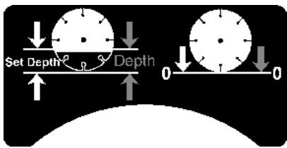
Blade Cutting Depth Information:
The saw is equipped with a BLADE DEPTH INDICATOR (1O) which has two number ranges. The Orange and White number ranges are used for two different purposes:
1) The "Depth" number range, indicated by the Orange color, shows the current Cutting Depth of the DIAMOND BLADE (2E). As the saw is lowered, the BLADE DEPTH INDICATOR (1O) needle travels through these numbers in increasing order. Or
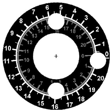
2) The "SMD" or "Set Maximum Depth" number range, indicated by the White color, is the uncut depth of the DIAMOND BLADE (2E). The desired maximum cutting depth is pre-set using the BLADE DEPTH INDICATOR (1O). It can be used with or without the BLADE DEPTH STOP SWITCH (1K) feature. As the saw is lowered, the BLADE DEPTH INDICATOR (1O) needle travels through the White color number range in decreasing order, indicating the unfinished depth of cut. When the BLADE DEPTH INDICATOR (1O) needle reaches "0" position, the desired maximum cutting depth is reached. If the BLADE DEPTH STOP SWITCH (1K) feature is used ("1" or "ON" position), the lowering process stops automatically.
Using the BLADE DEPTH INDICATOR (10):
"Depth" Mode (Orange colored numbers show current cutting depth):
- Turn ENGINE START SWITCH (1C) to "0" (OFF) position to STOP engine (If running).
- Turn ENGINE START SWITCH (1C) to "1" (RUN) position to power electrical system.
- Turn BLADE DEPTH STOP SWITCH (1K) to "0" (OFF) position.
- Lower DIAMOND BLADE (2E) by pushing the TOGGLE SWITCH (1N) on the SPEED CONTROL LEVER (1M)
downward until the DIAMOND BLADE (2E) touches the surface to be cut.
- Rotate the BLADE DEPTH INDICATOR (1O) needle to align to the "0" depth.
- As DIAMOND BLADE (2E) is lowered into the cutting surface, the current cutting depth will now be indicated by the Orange text number range on BLADE DEPTH INDICATOR (1O) needle.
SMD or "Set Maximum Depth" Mode without BLADE DEPTH STOP (White colored numbers show uncut depth):
- Turn ENGINE START SWITCH (1C) to "0" (OFF) position to STOP engine (If running).
- Turn ENGINE START SWITCH (1C) to “1” (RUN) position to power electrical system.
- Lower DIAMOND BLADE (2E) by pushing TOGGLE SWITCH (1N) on the SPEED CONTROL LEVER (1M) downward until DIAMOND BLADE (2E) touches the surface to be cut.
- Rotate the BLADE DEPTH INDICATOR (1O) needle to align with the desired maximum cutting depth on White colored number range. The uncut depth will now be indicated on the White colored number range. When the BLADE DEPTH INDICATOR (1O) needle gets to the "0" position, the saw is cutting at the desired maximum cutting depth.
- Raise the blade by pushing the TOGGLE SWITCH (1N) on the SPEED CONTROL LEVER (1M) upward until the DIAMOND BLADE (2E) is off of the cutting surface.
- Turn the ENGINE START SWITCH (1C) to the "0" (OFF) position to turn off power to electrical system.
SMD or "Set Maximum Depth" Mode using BLADE DEPTH STOP SWITCH (1O) (White colored numbers show uncut depth):
- Turn ENGINE START SWITCH (1C) to "0" (OFF) position to STOP engine (If running).
- Set the BLADE DEPTH STOP SWITCH (1K) to the "0" (OFF) position to override the depth stop setting. Saw will raise and lower over its full range without stopping.
- Turn ENGINE START SWITCH (1C) to “1” (RUN) position to power electrical system.
- Lower DIAMOND BLADE (2E) by pushing TOGGLE SWITCH (1N) on the SPEED CONTROL LEVER (1M) downward until DIAMOND BLADE (2E) touches the surface to be cut.
- Rotate the BLADE DEPTH INDICATOR (1O) needle to align with the desired maximum cutting depth on White colored number range.
- Set the BLADE DEPTH STOP SWITCH (1K) to "1" (ON) position.
- Raise the blade by pushing the TOGGLE SWITCH (1N) on the SPEED CONTROLLEVER (1M) upward until the DIAMOND BLADE (2E) is off of the cutting surface.
- Turn the ENGINE START SWITCH (1C) to the "0" (OFF) position to turn off power to electrical system.
- Now the maximum cutting depth is set. If the saw is raised out of the cut surface for any reason it can now be lowered to "Set Max. Depth" by lowering the blade until the saw lowering movement stops.

The saw WILL NOT lower to any depth greater than the position set on the BLADE DEPTH STOP SWITCH (1Q). If a deeper cut is required, the BLADE DEPTH INDICATOR (1Q) MUST be turned to the new depth position. Or push the BLADE DEPTH STOP SWITCH (1M) to "0" (OFF) position to override the Depth Stop Feature.
7 Stopping The Saw
(See Figures 1-2)

For EMERGENCY STOP, press down the RED PALM SWITCH (1J) on the cowl. This will stop the engine and disconnect power to all electrical items except lights. Reset the RED PALM SWITCH (1J) by pulling out until it pops up, then restart engine.
- Move the Control Lever (1M) to the STOP (1X) position.
- Raise the Diamond Blade (2E) out of the cut by pressing the Raise/Lower Switch (1N) on the Control Lever (1M) upward until the Diamond Blade (2E) clears the surface.
- Disengage the Blade Clutch Switch (1Y) if equipped with clutch.
- Press the Engine Throttle Switch (1E) to the LOW IDLE position.
- Turn off the Water Valve (1R).
- Let the Engine run at idle for a few minutes before shutting off.
- STOP the engine by turning the Engine Start Switch (1C) to the "0" (OFF) position.
8 Incidents During Sawing
(See Figures 1-2)
If ENGINE STOPS during sawing, check the following:
- Engine out of fuel—LCD Display (1F) Aux Shutdown SPN 970 FMI 31 Check Fuel Gauge (1AA).
- Lack of water signals the Water Safety Switch (1H) to stop the engine. LCD Display reads Active Fault Blade Coolant Flow Too Low SPN 111 FMI 16 Set Switch (1H) to “0” (OFF) and check water supply, then restart the engine.
- Excessively fast cutting speed will stall engine.
- Red Palm Emergency Switch (1J) has been pressed down. Reset by pulling toggle switch until it pops upward.
- Circuit Breaker Fuse is blown. Inspect and replace fuses in control box or harness.
If the Diamond Blade (2E) STOPS during sawing, check:
- Drive belt tension is inadequate.
- The clutch switch (1Y) has been pushed to "0" OFF
- The clutch has an electrical failure or blown fuse.
SAW LOWERS TOO FAST:
- The lowering rate of the saw can be adjusted using the Flow Control Valve (1T) at the rear or the saw. If the saw falls too quickly, turn the knob on the Flow Control Valve (1T) CLOCKWISE until an adequate lowering rate is set.
If the ENGINE or BLADE STALLS for any reason, raise
the blade completely from the cut, inspect the machine thoroughly before restarting the engine. When lowering the blade into a partial cut, align the blade exactly with the cut to prevent damage
to the blade.
Entrust all repairs to your authorized dealer only.
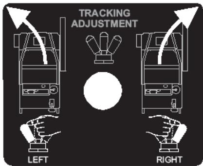
9 Adjustments: Straight Line Sawing
(See Figures 1 and 4)
While cutting, the saw may steer to the right from the required straight line marked on the cutting surface (if the Diamond Blade (2E) is installed on the right hand side). If this occurs, the Rear Axle (4E) of the saw can be pivoted to compensate for this situation.
Saw with EASYTRACK option.
- Push Axle Adjustment Switch (1G) to the LEFT. Small short adjustments make large changes.
Adjustments can be made while sawing or not sawing. - Visually confirm the axle movement and direction.
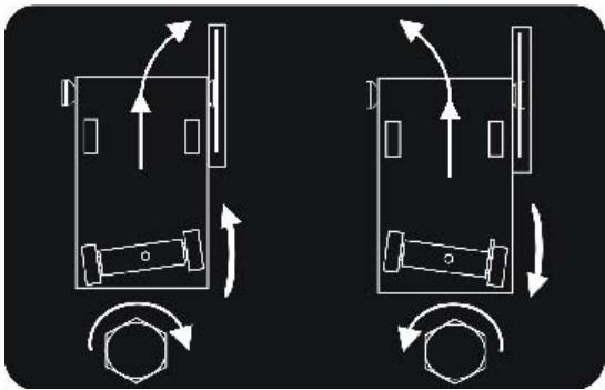
Saws with Manual Axle Adjustment
- The axle (4E) is adjusted by turning the M12 Adjustment Bolt (1V) located at the rear lower left of saw frame.
- If the saw steers to the RIGHT while sawing, Turn the Adjustment Bolt COUNTERCLOCKWISE.
- If the saw steers to the LEFT while sawing, Turn the Adjustment Bolt (1CC) CLOCKWISE.
10 Maintenance
(See Figures 1-6)

Before performing any maintenance, ALWAYS park the machine on a level surface with the Engine OFF and the Engine Start Switch (1C) in the “0” (OFF) position.

CP600 LCD Display (1F) will Alert operators to certain service requirements. See Electronics Service section
After each use CLEAN the machine.
LUBRICATION:
ENGINE OIL: Check daily (6B). Change Engine Oil and Oil Filter (6H) after every 100 HOURS of operation. See engine manual for oil type to use. 15W40 CD, CE is generally recommended. (6B) Capacity is 8.5 quarts (8.0 liters) with filter (6H). Align oil level with upper mark on dipstick (6B).
LUBRICATE EVERY 100 HOURS:
- Front Axle Pivot Bearings (4C)
LUBRICATE EVERY 250 HOURS:
- Bladeshaft Seals and Bearings (4A) 2 Pumps only
HYDRAULIC SYSTEM:
Refer to Section 12 - "Hydraulic System"
ENGINE GEARBOX (3-1A, 3-2A):
- Change oil after every 500 hours of operation. Use SAE 75W90 synthetic gear lubricant.
DO NOT OVERFILL! Fill only to "Check Port" or excess will overflow.
Single Speed ENGINE GEARBOX (3-1A): Oil Capacity is 32 oz. (USA) (0.946 Liter)
Three Speed ENGINE GEARBOX (3-2A): Oil Capacity is 60 oz. (USA) (1.77 Liter)
- Drain cooling water from Water Drain Valve (3-1C, 3-2C) to prevent rust and freeze damage (Every Day).
COOLING SYSTEM:
The engine cooling fluid is 50/50 anti freeze/water mixture.
- Clean the Radiator Air Filter Element (1U) every 50 hours or when required, replace if damaged. Always keep Radiator Air Filter Element (1U) in place. CLEAN Fuel cooler filter (1S) Clean CAC filter
- Check hoses and hose clamps for damage and looseness. Tighten or replace as required.
- Check Coolant Freeze Protection yearly.
- Flush and Clean radiator and cooling system every 500 hours.
- Maintain at least 1/4 full coolant level in Radiator Coolant Recovery bottle (1W) when engine is cool.
- Maintain Coolant level to within 1 inch of the top of the Surge Tank Cap (5B).
AIR FILTER :
- Clean the Air Filter Outer Element (5A) when the Restriction Indicator (1L) Red Signal appears. DO NOT clean the Inner Safety Element (5A)!
To change or clean the air filter element:
-
Remove the Air Filter Housing (5A) by opening the three (3) Air Filter Housing Clamps, and pulling the housing off.
-
Pull the Air Filter Outer Element out of the filter housing and replace, or clean by using low pressure compressed air [2.75 bars (40 psi - MAX)] from the inside out. DO NOT clean the filter element by tapping it on the ground or other objects, this will damage the

filter element!
Install Air Filter Outer Element by pushing it into the housing.
Install the Air Filter Housing (5A) and the three (3) Air Filter Housing Clamps (5A).
The three (3) Air Filter Housing Clamps (5A) can NOT be closed unless the Air Filter Outer Element is properly installed.
- Replace the Inner Safety Element once per year or if it becomes damaged.
- Replace any damaged filters or gaskets.
- Check air hose and clamps for damage or looseness. Tighten or replace as required.
Wheels and Hubs:
- Check for excess wear and looseness. Tighten or replace as required.
FUEL FILTER :
- Replace Spin-On Fuel Filter (5F) every 500 hours.
11 Blade Shaft V-Belt Tension
(See Figures 1-3)
This saw is equipped with high tension banded V-belts. The belts are properly tensioned at the factory but after a few hours of operation they will stretch and become loose. Re-tension belts as described below.
To Tension V-Belts:
- Turn ENGINE START SWITCH (1C) to the "0" (OFF) position.
- Open ENGINE HOOD (6E): See Figure(s) 3-1/3-2, Item 3-1D/3-2D for procedure.
- Using the BLADE SHAFT WRENCH (2J), loosen the horizontal clamping bolts (3K) at the front of the machine.
- Turn each of the two (2) vertical BELT TENSIONING BOLTS (3-1J, 3-2J) [at the front of machine, below the ENGINE GEARBOX (3-1A, 3-2A)] CLOCKWISE until the V-BELTS (3-1M, 3-2M) are tight.
- Replace V-BELTS (3-1M, 3-2M) in complete sets only.
- For optimum V-Belt tension use Goodyear TensionRite™ Strips, P/N 542 19 13-68. TensionRite™ strips are supplied with belts purchased from your dealer.
- Never tension V-BELTS (3-1M, 3-2M) beyond the original factory tension. Loose V-Belts result in poor saw performance and short belt life.

Replace all shields and guards. Never run Saw with out all shields and guards in place.
12 Hydraulic System
(See Figures 1-6)
The hydraulic system on this saw is used to RAISE/ LOWER the Diamond Blade (2E), and to propel the saw FORWARD and REVERSE. The hydraulic system consists of a Hydrostatic Pump (5M), (2) Hydraulic Wheel Motors (4F), Hydraulic Filter (5K), DC Lift Pump (5H), Hydraulic Oil Reservoir (5J), Flow Control Valve (1U), and Hydraulic Lift Cylinder (4G).
- Hydraulic Filter (5J) should be changed after the first 50 hours of operation, then every 250 hours of operation.
- Check Hydraulic Reservoir (5l) fluid level periodically. Maintain oil level with SAE 15W40 API Class SE, CC, CD motor oil. DO NOT OVERFILL, check oil level when saw is level.
- Change hydraulic fluid every 500 hours of operation. Fill Hydraulic Reservoir (51,5G) with approximately 2.5 quarters of SAE 15W40 API Class SE, CC, CD motor oil. DO NOT OVERFILL! Check oil level when saw is level.
- The lowering rate of the saw can be adjusted using the Flow Control Valve (1T) at the rear of the saw. If the saw falls too quickly, turn the knob on the Flow Control Valve (1T) CLOCKWISE until an adequate lowering rate is set.
13 Important Advice
(See Figures 2-3)
- Tighten loose nuts and bolts regularly, particularly after several hours of operation.
- Check V-Belt (3-1M, 3-2M) tension regularly. Re-tighten V-Belts (3-1M, 3-2M) as necessary.
- Remove the Diamond Blade (2E) for storage. Store it carefully.
- Check the water spray over the Diamond Blade (2E) periodically.
- Tighten the Diamond Blade (2E) firmly on the Blade Arbor (2C). Always use Lockwasher (2J) with bladeshaft Bolt (2A)Replace when worn or damaged.
- Make sure the contact faces of Flanges (2B & 2F), Diamond Blade (2E), and Blade Shaft (2I) are clean.
Store in a safe place out of reach of children.
Remove all adjustment tools and wrenches. Store diamond tool in a safe place so it cannot be damaged.
14 Engine / Blade Shaft / Gearbox Speed Adjustment
(See Figures 1-6)

WARNING: Serious injury can occur to the operator or people in the work area if the rotational speed (n/min) of the DIAMOND BLADE (2E) exceeds the maximum speed (n/min) marked on the DIAMOND BLADE (2E).
ENGINE SPEED:
The engine speed on this machine does not need to be changed from the factory set speed. The maximum engine RPM should be 2870, no load.
BLADE SHAFT SPEED:
The blade shaft speed on this machine should be checked before fitting the DIAMOND BLADE (2E) to the machine. Never install a DIAMOND BLADE (2E) if the blade shaft rotational speed (n/min) of the machine is greater than the maximum speed (n/min) marked on the DIAMOND BLADE (2E)! The BLADE SHAFT PULLEY (3-1N, 3-2N) and BLADE SHAFT FLANGE (2B & 2F) may need to be changed if the diameter of the Diamond Blade is changed!
Each saw model, as delivered from the factory, is designed to operate with a specified range of blade sizes inside the blade guard installed on the machine. If a blade size outside the specified range of sizes for your model must be used, then the saw drive configuration must be changed.
If changing from a small to a very large DIAMOND BLADE (2E) on a machine with a single speed gearbox, the Blade Shaft Pulleys (3-1L), Gearbox Pulleys (3-1N), the BLADE SHAFT FLANGES (2B & 2F), and the Blade Guard must be changed.
For example, to change a single speed gearbox model from a 18" (450mm) drive to a 36" (900mm) drive:
- Change Engine Gearbox Pulley from 4.75" (121mm) diameter to 3.65" (93mm) diameter.
- Change Blade Shaft Pulley from 4.12" (105mm) diameter to 5.60" (142.2mm) diameter.
- Change Blade Flanges from 5.00" (127mm) diameter to 6" (152mm) diameter.
- Change BLADE GUARD (2H) from 18" (450mm) to 36" (900mm).
- Engine Speed does not change.
See Blade Size Conversion charts for specific information.
THREE SPEED GEARBOX MODEL (14-26, 18-30, 20-36, 26-42, 30-48, 36-60):

CAUTION: Never shift the Gearbox (3-2A) with engine running! Only shift the Gearbox (3-2A) with engine OFF! Gearbox damage could occur.
See "GEARBOX SHIFT LEVER (3-2O)" for details about operating shift lever.
A machine factory equipped with a Three Speed ENGINE GEARBOX (3-2A), while designed to minimize adjustments required for blade size changes, will require some adjustments. The machine is designed to operate with a specified range of blade sizes inside the factory installed blade guard. Color coded information on machine, and information in operation manual, shows allowable blade sizes for current machine drive configuration. There are six (6) machine drive configurations: a) 14-26 for 14^ to 26^ (350 to 650~mm ) blades, b) 18-30, for 18^ to 30^ (450 to 750~mm ) blades, c) 20-36, for 20^ to 36^ (500 to 900~mm ) blades, d) 26-42 for 26^ to 42^ (650-1000 mm) blades, e) 30-48 for 30^ to 48^ (760-1219 mm) blades f) 36^ - 60^ (900-1500mm)(FS 8400 D). For example, to change the blade size on a machine drive configuration 18-30 within these range, 18^ to 30^ (450 to 750~mm ), requires only that GEARBOX SHIFT LEVER (3-2O) be moved into the correct position (1, 2, or 3). If the required blade size is outside of the machine drive configuration range [below 18^ (450mm) or above 30^ (750 mm) for this example], then the machine drive configuration must be changed. This may require shifting the GEARBOX SHIFT LEVER (3-2O), changing BLADE SHAFT PULLEYS (3-2L), GEARBOX PULLEYS (3-2N) and BLADE SHAFT FLANGES (2B & 2F).
Example: To change a three-speed gearbox model from a 20" (500mm) drive to a 36" (900mm) drive, first determine the machine drive configuration (14-26, 18-30, 20-36, 26-42, or 30-48). This should correspond to the BLADE SHAFT FLANGE (2B & 2F) diameter installed on the saw.
If the machine drive configuration is a 20-36, the FLANGE (2B & 2F) diameter is should be 6.00'' (152mm):
a) Verify proper pulley diameters are installed (See Blade Size Conversion charts for specific information).
b) Shift the GEARBOX SHIFT LEVER (3-2O) from 3 to 1.
c) Verify that machine drive configuration and blade shaft speed corresponds with information in operation manual, and gearbox range decal (522627702).
If the machine drive configuration is an 18-30, the FLANGE (2B & 2F) diameter should be 5.00'' (127mm):
a) Change the BLADE SHAFT PULLEY from 4.12" (105 mm) diameter to 4.75" (121mm).
b) Change the BLADE SHAFT FLANGE from 5.00" (127mm) diameter to 6.00" (152mm).
c) Shift the GEARBOX SHIFT LEVER (3-2O) from 2 to 1.
d) Verify that machine drive configuration and blade shaft speed corresponds with 20-36 drive configuration information in operation manual.
e) Install the 20-36 drive configuration decals (Decal 522627704 is required). See the "Decals and Locations" page of this manual for more information.
If the machine drive configuration is a 14-26, the FLANGE (2B & 2F) diameter should be 4.50'' (114.3mm):
a) Change the BLADE SHAFT PULLEY from 4.12" (105mm) diameter to 4.75" (121mm).
b) Change the BLADE SHAFT FLANGE from 4.50"
(114.3mm) diameter to 6.00" (152mm).
c) Change the ENGINE GEARBOX PULLEY from 4.75" (121mm) diameter to 4.12" (105mm).
d) Shift the GEARBOX SHIFT LEVER (3-2O) from 2 to 1.
e) Verify that machine drive configuration and blade shaft speed corresponds with 20-36 drive configuration information in operation manual.
f) Install the 20-36 drive configuration decals (Decal 522627702 is required). See the "Decals and Locations" page of this manual for more information.
See Blade Size Conversion charts for specific information.

WARNING: Serious injury can occur to the operator or people in the work area if the rotational speed (n/min) of the DIAMOND BLADE (2E) exceeds the maximum speed (n/ min) marked on the DIAMOND BLADE (2E).

WARNING: After Shifting Gearbox, lower GEARBOX DETENT KNOB (3-2P) or three-speed ENGINE GEARBOX (3-2A) could be damaged!
If gearbox seems hard to shift, a slight movement of the blade shaft may ease movement of GEARBOX SHIFT LEVER (3-2O) into proper gear. Never shift the Gearbox (3-2A) with engine running!
Two Neutral positions are available in the Three Speed ENGINE GEARBOX (3-2A). This gearbox can be shifted into neutral if the blade rotation needs to be eliminated while the engine is running. If the machine is equipped with the optional BLADE CLUTCH (1Y), the BLADE CLUTCH SWITCH (1Y) can be moved to the "0" (OFF) position to eliminate blade rotation while the engine is running.
15 Accessories
BLADE GUARD CONVERSION KITS:
Use the proper size blade guard for the particular diamond blade size being operated. The following blade guards are available for these diamond blade sizes:
| Guard | Blade Sizes |
| 60" (1500mm) | 48" - 60" (1200 - 1500mm) |
| 48" (1200mm) | 36" - 48" (1000 - 1200mm) |
| 42" (1000mm) | 30" - 42" (750 - 1000mm) |
| 36" (900mm) | 24" - 36" (600 - 900mm) |
| 30" (750mm) | 18" - 30" (450 - 750mm) |
| 26" (600mm) | 14" - 26" (350 - 650mm) |
| 18" (450mm) | 14" - 18" (350 - 450mm) |
See Blade Size Conversion charts for specific information.
WEIGHT KITS:
Standard as on: 42" (1000mm), 48" (1200mm) & 60" (1500mm).
542 19 61-72 Kit, Rear weights 2 Bars 42"
542 19 80-22 Kit, Rear weights 3 Bars 48"
542 19 97-57 Kit, Rear weights 6 Bars 60"
(includes: Side weights) 5 Bars w/ handles
OPTIONAL KITS:
542 18 11-17* Dual Light Kit
542 19 96-26 Water Pump Kit
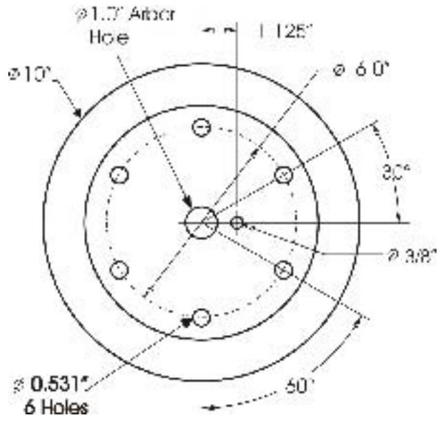
16 Large Diameter Models
The FS8400 can be configured with a 60" (1500mm) diameter blade capacity. The 60" drive can be ordered from the factory or can be reconfigured by ordering the conversion kit 542 19 96-25. See the Blade Size Conversion Chart for specifics. Depth of cut of 25" can be achieved. The large diameter model includes a frame extension, 60" blade guard and a blade shaft assembly with 10"
diameter flanges. The Flanges have the following pattern.
The Blade Hole pattern must match. Six (6), 12 - 13 × 2.5 long Hex Head Cap Screws pass through the outer flange through the blade core and thread into the inner flange supplying the clamping force to hold the blade. Use 12 lock washers with the clamping bolts. Also use the 5/8 - 11 × 4.0 Cap Screw, LH or RH thread through the center of the flange. Husqvarna will supply blades with this hole pattern.
The FS8400, when equipped with a 60" drive system is very heavy and the machine balance is greatly affected by installing or removing a blade. To counter the large balance changes, a weight box is mounted on the left or right rear of the saws. Weights can be easily removed and added to quickly adjust the machine balance to meet the operator's needs.
17 Repairs
We carry out all repairs in the shortest possible time and at the most economical prices. (See back page for our address and phone numbers.) Contact you authorized Dealer concerning maintenance and repairs.
18 Spare Parts
For quick supply of spare parts and to avoid any lost time, it is essential to quote the data on the manufacturers plate fixed to the machine and the part number(s) and description to be replaced with every order.
Please reference Parts Lists manual (521 970 902): (If you do not have a Parts List Manual, please call TOLL FREE 1-800-288-5040 in USA, or for International, call +1-913-928-1300.)
Refer to Electronic Controls/ Display Manual (COEN2009_115159727.PDF) for Fault Codes and electronic Issues. Manual available On Line at http://us.husqvarnacp.com. Navigate to service. Search for FS6600 FS8400 Electronic Controls/ Display Manual
The instructions for use and spare parts found in this document are for information only and are not binding. As part of our product quality improvement policy, we reserve the right to make any and all technical modifications without prior notice.

The manufacturer accepts no responsibility caused by unsuitable use or modifications.
LISTA DE COMPROBACION PRELIMINAR

Unaquina equipada en fabrica con una CAJA DE ENGRANAJES DE MOTOR (3-2A) de tres velocidades, although it's already been used in the market. The machine is equipped with a 1000 kg motor and a 1500 kg fuel tank. It can be used for any purpose, including for use in the construction of homes, schools, and hospitals.