
9659972-01 - Agricultural accessory HUSQVARNA - Free user manual and instructions
Find the device manual for free 9659972-01 HUSQVARNA in PDF.

| Category | Agricultural accessory |
| Brand | Husqvarna |
| Model | 9659972-01 |
| Product type | Leveling blade |
| Intended use | Leveling, snow removal, light earthmoving |
| Cutting width | Approximately 1.8 m |
| Weight | Approximately 200 kg |
| Power supply | Hydraulic (connection to tractor circuit) |
| Main functions | Left/right tilt, shock function |
| Adjustments | Tilt via lever, height via adjustable skids |
| Maintenance | Regular greasing of 9 fittings with bearing grease |
| Safety | Stop the engine and remove the key before maintenance; keep hands away from moving parts |
| Spare parts | Skids, solenoid valve, hydraulic hoses, electrical cable, quick couplings |
| Repairability | Adjustment and replacement of skids, maintenance of cylinders and hydraulic fittings |
| Warranty | Consult the manual or dealer |
| Manual available in | French, English, German, Finnish, Swedish and others on request |
Frequently Asked Questions - 9659972-01 HUSQVARNA
User questions about 9659972-01 HUSQVARNA
0 question about this device. Answer the ones you know or ask your own.
Ask a new question about this device
Download the instructions for your Agricultural accessory in PDF format for free! Find your manual 9659972-01 - HUSQVARNA and take your electronic device back in hand. On this page are published all the documents necessary for the use of your device. 9659972-01 by HUSQVARNA.
USER MANUAL 9659972-01 HUSQVARNA
Owner's manual, p. 18-25
Read through the owner's manual carefully before you begin using the product.
Study and understand the owner's manual before use.
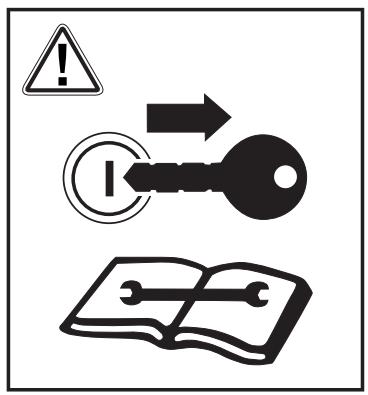
Turn off the engine and remove the key before maintenance, cleaning or repair.
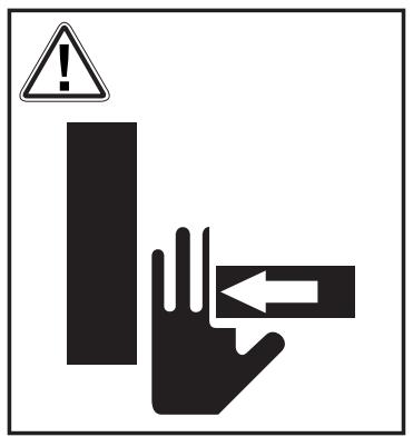
Risk of crush injuries! Keep hands and feet away from moving parts when the V- plough is in operation.
Fit the bracket.
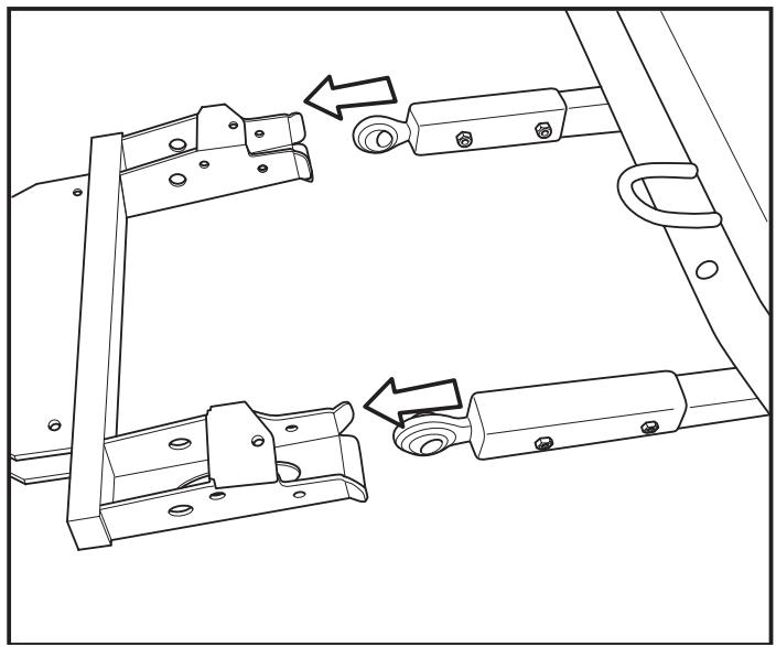
If necessary adjust the plough so that it operates in the horizontal position, by pulling the lever forward or backward.
Make sure all the sprinters are securely locked when the V-plough unit is mounted to the PT 26D.
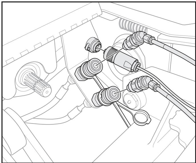
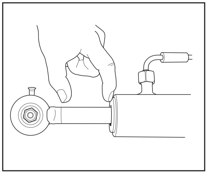
The hydraulic hoses and the electric cable are connected under the hatch in the footplate.
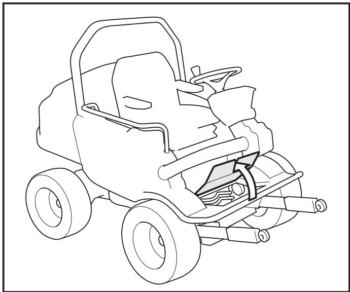
Connect hoses and the electric cable.
NOTE! In some cases it can be necessary to post tension the hoses and quick couplings the first time the V- plough is used.
To facilitate engagement and disengagement the notch must be in this position.
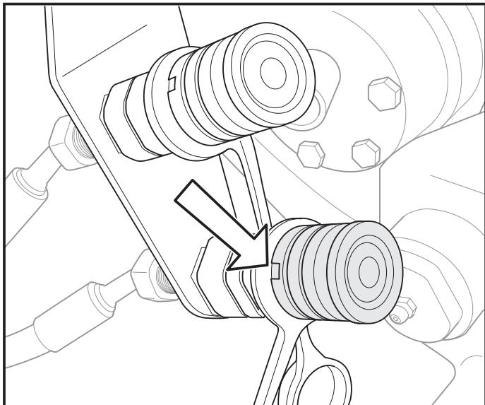
Position of the cylinder
The cylinder should always be extended at least 50 mm .
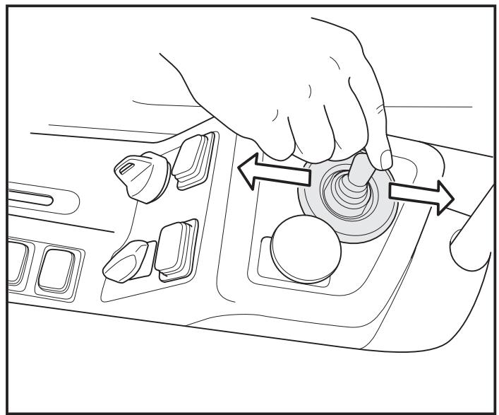
Reducing pressure
Turn the key to ON for a few seconds and simultaneously pull the lever to the right and left a few times to reduce the pressure in the plough's cylinder.
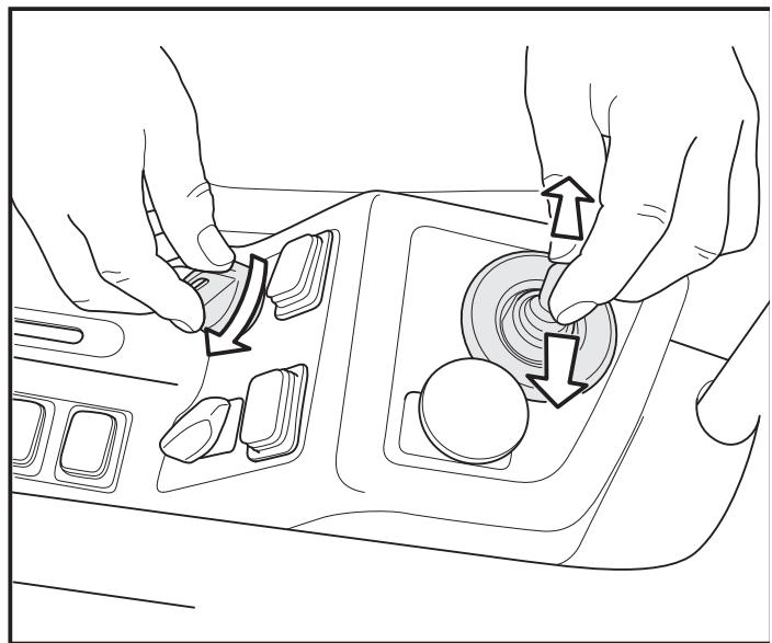
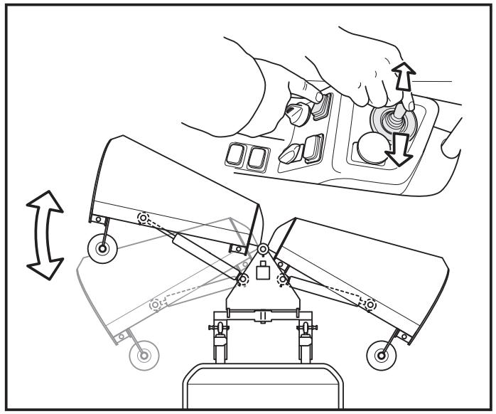
Press down the button's left side and then move the lever to right and left to adjust the left plough plough
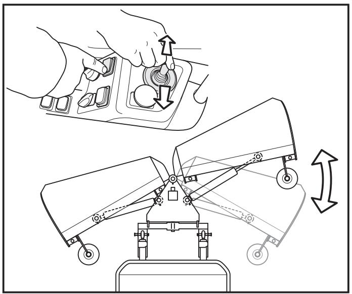
Press down the button's right side and then move the lever to right and left to adjust the right plough plough.
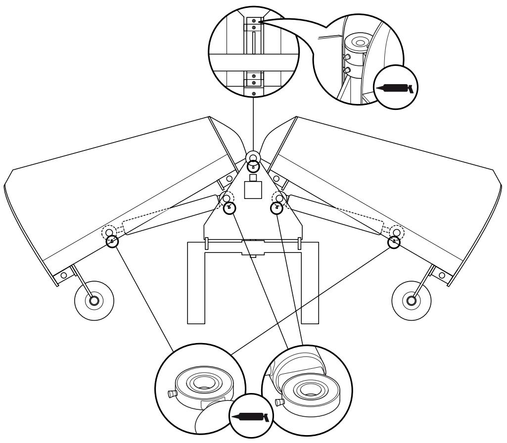
Lubricate with ball bearing grease.
There are nine grease nipples on the plough. Five of them are located on the centre joint. The remaining four are on the cylinder's ends (joints').
Lubricate them regularly with ball bearing grease. Check the lubrication points before each day of use.
The plough is lubricated on delivery.
With or without shock function: 1 / 4", 3 / 8", 3 / 8" shock
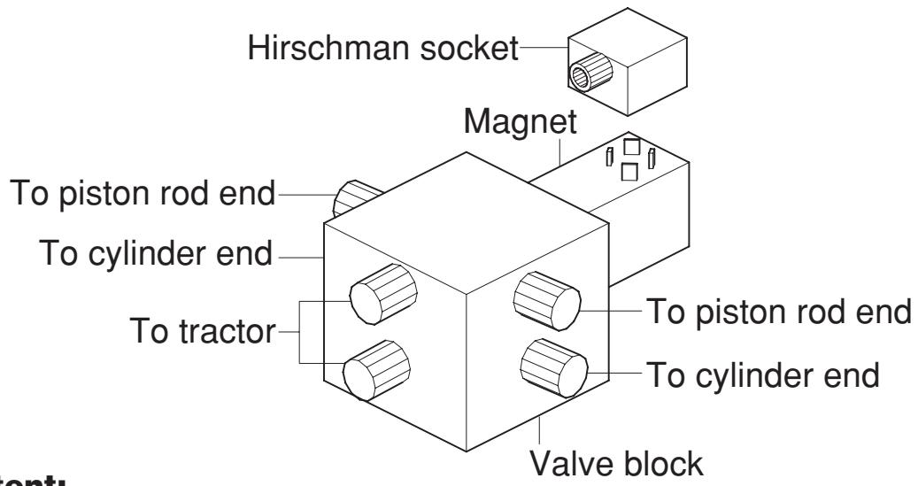
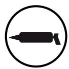
Hose mounting:
Content:
- Diode*
- Fuse holder
- Hirschman socket
- 4 m twin conductor
- Terminal; female + male
- Lever with switch (not standard)
*NOTE! The diode must be fitted between plus and minus inside the Hirschman socket. Otherwise there is a risk of the switch in the lever breaking due to sparking.
Electric valve with shock function
When in use ploughs equipped with this type of electric valve should not be operated with the pistons fully retracted. They should be extended approx. 50 mm . Otherwise the shock function is triggered.
The valve is adjustable with respect to opening pressure.
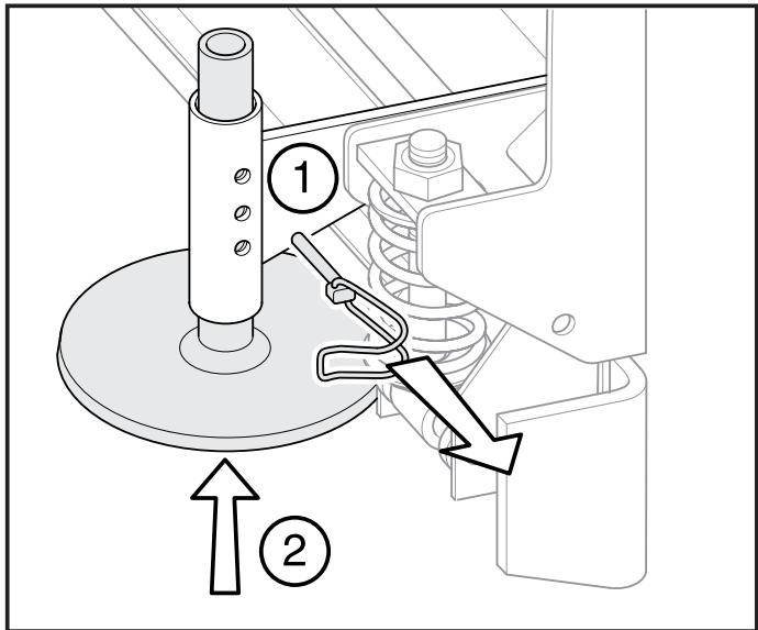
The collector shoes can be adjusted in steps of 5mm . For maximum use of the plough they should be adjusted to a suitable height.
Check that right and left are at the same height.
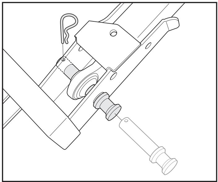
- Remove the pin
- Adjust the height
- Secure the pin
Mobile: +46(0)70-567 00 11
Fax: +46(0)44-340350
Brand : HUSQVARNA
Model : 9659972-01
Category : Agricultural accessory