
XS-84H - Uncategorized ROLAND - Free user manual and instructions
Find the device manual for free XS-84H ROLAND in PDF.


User questions about XS-84H ROLAND
0 question about this device. Answer the ones you know or ask your own.
Ask a new question about this device
Download the instructions for your Uncategorized in PDF format for free! Find your manual XS-84H - ROLAND and take your electronic device back in hand. On this page are published all the documents necessary for the use of your device. XS-84H by ROLAND.
USER MANUAL XS-84H ROLAND
Owner's Manual (this document)
Read this first. It explains the basic things you need to know in order to use the XS-82H/XS-83H/XS-84H.

PDF Manual (download from the Web)
•Reference Manual
This describes all parameters of the XS-82H/XS-83H/XS-84H. It also describes the settings to make when operating the unit by remote control.

To obtain the PDF manual
- Enter the following URL in your computer. https://proav.roland.com/manuals/
- Choose "XS-82H," "XS-83H," or "XS-84H" as the product name.
Copyright © 2014 ROLAND CORPORATION
All rights reserved. No part of this publication may be reproduced in any form without the written permission of ROLAND CORPORATION.
WARNING: To reduce the risk of fire or electric shock, do not expose this apparatus to rain or moisture.

ATTENTION
CAUTION
RISK OF ELECTRIC SHOCK
DO NOT OPEN

RISQUE DE CHOC ELECTRIQUE NE PAS OUVRIR
CAUTION: TO REDUCE THE RISK OF ELECTRIC SHOCK, DO NOT REMOVE COVER (OR BACK). NO USER-SERVICEABLE PARTS INSIDE. REFER SERVICING TO QUALIFIED SERVICE PERSONNEL.

The lightning flash with arrowhead symbol, within an equilateral triangle, is intended to alert the user to the presence of uninsulated “dangerous voltage” within the product's enclosure that may be of sufficient magnitude to constitute a risk of electric shock to persons.

The exclamation point within an equilateral triangle is intended to alert the user to the presence of important operating and maintenance (servicing) instructions in the literature accompanying the product.
INSTRUCTIONS PERTAINING TO A RISK OF FIRE, ELECTRIC SHOCK, OR INJURY TO PERSONS.
IMPORTANT SAFETY INSTRUCTIONS SAVE THESE INSTRUCTIONS
WARNING - When using electric products, basic precautions should always be followed, including the following:
- Read these instructions.
- Keep these instructions.
- Heed all warnings.
- Follow all instructions.
- Do not use this apparatus near water.
- Clean only with a dry cloth.
- Do not block any of the ventilation openings. Install in accordance with the manufacturers instructions.
- Do not install near any heat sources such as radiators, heat registers, stoves, or other apparatus (including amplifiers) that produce heat.
-
Do not defeat the safety purpose of the polarized or grounding-type plug. A polarized plug has two blades with one wider than the other. A grounding type plug has two blades and a third grounding prong. The wide blade or the third prong are provided for your safety. If the provided plug does not fit into your outlet, consult an electrician for replacement of the obsolete outlet.
-
Protect the power cord from being walked on or pinched particularly at plugs, convenience receptacles, and the point where they exit from the apparatus.
- Only use attachments/accessories specified by the manufacturer.
- Unplug this apparatus during lightning storms or when unused for long periods of time.
- Refer all servicing to qualified service personnel. Servicing is required when the apparatus has been damaged in any way, such as power-supply cord or plug is damaged, liquid has been spilled or objects have fallen into the apparatus, the apparatus has been exposed to rain or moisture, does not operate normally, or has been dropped.
-For the U.K.
WARNING: THIS APPARATUS MUST BE EARTHED
IMPORTANT: THE WIRES IN THIS MAINS LEAD ARE COLOURED IN ACCORDANCE WITH THE FOLLOWING CODE. GREEN-AND-YELLOW: EARTH, BLUE: NEUTRAL, BROWN: LIVE
As the colours of the wires in the mains lead of this apparatus may not correspond with the coloured markings identifying the terminals in your plug, proceed as follows:
The wire which is coloured GREEN-AND-YELLOW must be connected to the terminal in the plug which is marked by the letter E or by the safety earth symbol ↓ or coloured GREEN or GREEN-AND-YELLOW.
The wire which is coloured BLUE must be connected to the terminal which is marked with the letter N or coloured BLACK. The wire which is coloured BROWN must be connected to the terminal which is marked with the letter L or coloured RED.
USING THE UNIT SAFELY 5
CONSIGNES DE SÉCURITÉ
French language for Canadian Safety Standard
IMPORTANT NOTES 9
Panel Descriptions....10
Front Panel/Top Panel/Side Panel 10
Rear Panel 12
Placement and Setup 13
Important Notes on Rack Mounting....13
Attaching the Rubber Feet 13
Connecting Cables to the Euroblock Plugs 13
Connecting External Equipment....14
Connecting Video Source/Output Equipment 14
Connecting Audio Source/Output Equipment....15
Using Phantom Power 15
Connecting the Power Cord....16
Basic Operation....17
Turning the Power On and Off....17
Using the Menus....17
Changing the View on the Display 18
Changing Audio Fader Assignments....18
Video Operations 19
Setting the Video Signal for Each Video Input Channel....19
Sharing a Video Source (SHARE) 19
Changing Cross Points....19
Inputting/Outputting Copyright-protected (HDCP) Video .....20
Switching Between HDMI Output and HDBaseT Output .....21
Outputting an Imported Still Image 21
Switching the Video Output Mode 22
Applying a Fade to Output Video 24
Audio Operations....25
Adjusting Microphone Gain....25
Adjusting the Volume Balance of Input Audio 25
Adjusting the Volume Level of Output Audio 26
Other Features....27
Saving/Recalling Settings (Presets)....27
Saving Settings on a USB Flash Drive 27
Formatting USB Flash Drives 28
Returning Settings to the Factory-default State (Factory Reset) ....28
Remote Control from an External Device....28
Appendices 29
Troubleshooting....29
Block Diagram....31
Connector Specifications 32
Analog video INPUT connectors ....32
RS-232C connector....32
AUDIO INPUT/OUTPUT connectors....33
Main Specifications 34
Dimensions 36
* Before using this unit, carefully read the sections entitled "IMPORTANT SAFETY INSTRUCTIONS" (p. 2), "USING THE UNIT SAFELY" (p. 5), and "IMPORTANT NOTES" (p. 9). These sections provide important information concerning the proper operation of the unit. Additionally, in order to feel assured that you have gained a good grasp of every feature of your new unit, read Owner's Manual in its entirety. This manual should be saved and kept on hand as a convenient reference.
* The explanations of operation procedures in this document use illustrations of the XS-84H. Unless explicitly indicated to be for a specific model (such as "XS-84H only"), the explanations also cover the XS-82H and XS-83H as well.
Checking the Included Items
The following items are included with this unit. Check to make sure that all items are present. If anything is missing, contact your dealer.
□The unit

text_image
XSB4 100% 100% 100% 100% 100% 100% 100% 100% 100% 100% 100% 100% 100% 100% 100% 100% 100% 100% 100% 100% 100%* The appearance of each model differs.
□Power cord □Owner's Manual
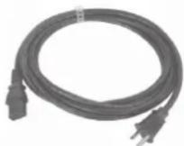
* The shape of the power cord's plug varies depending on the country.
□Rubber foot (5)
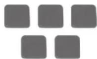
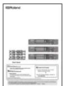
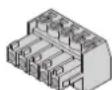
□Euroblock plug (12)
INSTRUCTIONS FOR THE PREVENTION OF FIRE, ELECTRIC SHOCK, OR INJURY TO PERSONS
About ⚠️ WARNING and ⚠️ CAUTION Notices
| [CAKS] WARNING | Used for instructions intended to alert the user to the risk of death or severe injury should the unit be used improperly. |
| [SW3K] CAUTION | Used for instructions intended to alert the user to the risk of injury or material damage should the unit be used improperly.* Material damage refers to damage or other adverse effects caused with respect to the home and all its furnishings, as well to domestic animals or pets. |
About the Symbols
| The △symbol alerts the user to important instructions or warnings. The specific meaning of the symbol is determined by the design contained within the triangle. In the case of the symbol at left, it is used for general cautions, warnings, or alerts to danger. | |
| The Ⓧsymbol alerts the user to items that must never be carried out (are forbidden). The specific thing that must not be done is indicated by the design contained within the circle. In the case of the symbol at left, it means that the unit must never be disassembled. | |
| The ●symbol alerts the user to things that must be carried out. The specific thing that must be done is indicated by the design contained within the circle. In the case of the symbol at left, it means that the power-cord plug must be unplugged from the outlet. |

WARNING
Make sure that the power cord is grounded
Connect mains plug of this model to a mains socket outlet with a protective earthing connection.

To completely turn off power to the unit, pull out the plug from the outlet
Even with the power switch turned off, this unit is not completely separated from its main source of power. When the power needs to be completely turned off, turn off the power switch on the unit, then pull out from the outlet. For this reason, the outlet is you choose to connect the power cord's pl be one that is within easy reach and readily

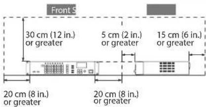
Secure a sufficient amount of space at the setup location
Since this unit normally emits a slight amount of heat, make sure to secure sufficient space around it, as shown below.

text_image
Front S 30 cm (12 in.) or greater 5 cm (2 in.) or greater 15 cm (6 in.) or greater 20 cm (8 in.) or greater 20 cm (8 in.) or greaterDo not disassemble or modify by yourself
Do not carry out anything unless you are instructed to do so in the owner's manual. Otherwise, you risk causing malfunction.

Do not repair or replace parts by yourself
Refer all servicing to your retailer, the nearest Roland Service Center, or an authorized Roland distributor, as listed on the "Information."

ALWAYS OBSERVE THE FOLLOWING

WARNING
Do not use or store in the following types of locations
- Subject to temperature extremes (e.g., direct sunlight in an enclosed vehicle, near a heating duct, on top of heat-generating equipment); or are
- Damp (e.g., baths, washrooms, on wet floors); or are
- Exposed to steam or smoke; or are
- Subject to salt exposure; or are
- Exposed to rain; or are
• Dusty or sandy; or are
• Subject to high levels of vibration and shakiness.


Do not place in an unstable location
Otherwise, you risk injury as the result of the unit toppling over or dropping down.

Use only the supplied power cord
Use only the attached power cord. Also, the supplied power cord must not be used with any other device.

Connect the power cord to an outlet of the correct voltage
The unit should be connected to a power supply only of the type described in the operating instructions, or as marked on the rear side of unit.

Do not bend the power cord or place heavy objects on it
Otherwise, fire or electric shock may result.

Avoid extended use at high volume
Use of the unit at high volume for extended periods of time may cause hearing loss. If you ever experience any hearing loss or ringing in the ears, you should immediately stop using the unit and consult a specialized physician.


WARNING
Do not allow foreign objects or liquids to enter unit; never place containers with liquid on unit
Do not place containers containing liquid (e.g., flower vases) on this product. Never allow foreign objects (e.g., flammable objects, coins, wires) or liquids (e.g., water or juice) to enter this product. Doing so may cause short circuits, faulty operation, or other malfunctions.


Turn off the unit if an abnormality or malfunction occurs
Immediately turn the unit off, remove the power cord from the outlet, and request servicing by your retailer, the nearest Roland Service Center, or an authorized Roland distributor, as listed on the "Inform" The power cord has been damaged;

• If smoke or unusual odor occurs; or
- Objects have fallen into, or liquid has been spilled onto the unit; or
- The unit has been exposed to rain (or otherwise has become wet); or
- The unit does not appear to operate normally or exhibits a marked change in performance.
Do not drop or subject to strong impact
Otherwise, you risk causing damage or malfunction.

Do not share an outlet with an unreasonable number of other devices
Otherwise, you risk overheating or fire.

Do not use overseas
Before using the unit in overseas, consult with your retailer, the nearest Roland Service Center, or an authorized Roland distributor, as listed on the "Information."

CAUTION
Place in a well ventilated location
The unit should be located so that its location or position does not interfere with its proper ventilation.

When disconnecting the power cord, grasp it by the plug
To prevent conductor damage, always grasp the power cord by its plug when disconnecting it from this unit or from a power outlet.

Periodically clean the power plug
An accumulation of dust or foreign objects between the power plug and the power outlet can lead to fire or electric shock.

At regular intervals, be sure to pull out the power plug, and using a dry cloth, wipe away any dust or foreign objects that may have accumulated.
Disconnect the power plug whenever the unit will not be used for an extended period of time
Fire may result in the unlikely event that a breakdown occurs.

Route all power cords and cables in such a way as to prevent them from getting entangled
Injury could result if someone were to trip on a cable and cause the unit to fall or topple.

Avoid climbing on top of the unit, or placing heavy objects on it
Otherwise, you risk injury as the result of the unit toppling over or dropping down.

Never connect/disconnect a power plug if your hands are wet
Otherwise, you could receive an electric shock.

Disconnect all cords/cables before moving the unit
Before moving the unit, disconnect the power plug from the outlet, and pull out all cords from external devices.

Before cleaning the unit, disconnect the power plug from the outlet
If the power plug is not removed from the outlet, you risk receiving an electric shock.

Whenever there is a threat of lightning, disconnect the power plug from the outlet
If the power plug is not removed from the outlet, you risk receiving an electric shock.

Precautions concerning use of phantom power supply
Always turn the phantom power off when connecting any device other than condenser microphones that require phantom power. You risk causing damage if you mistakenly supply phantom power to dynamic microphones, audio playback devices, or other devices that don't require such power. Be sure to check the specifications of any microphone you intend to use by referring to the manual that came with it. (This instrument's phantom power: 48 V DC, 14 mA Max)

INSTRUCTIONS POUR LA PRÉVENTION DES INCENDIES, CHOCS ÉLECTRIQUES OU BLESSURES
- Do not connect this unit to same electrical outlet that is being used by an electrical appliance that is controlled by an inverter or a motor (such as a refrigerator, washing machine, microwave oven, or air conditioner). Depending on the way in which the electrical appliance is used, power supply noise may cause this unit to malfunction or may produce audible noise. If it is not practical to use a separate electrical outlet, connect a power supply noise filter between this unit and the electrical outlet.
Placement
- Using the unit near power amplifiers (or other equipment containing large power transformers) may induce hum. To alleviate the problem, change the orientation of this unit; or move it farther away from the source of interference.
- This unit may interfere with radio and television reception. Do not use this unit in the vicinity of such receivers.
- Noise may be produced if wireless communications devices, such as cell phones, are operated in the vicinity of this unit. Such noise could occur when receiving or initiating a call, or while conversing. Should you experience such problems, you should relocate such wireless devices so they are at a greater distance from this unit, or switch them off.
- Do not expose the unit to direct sunlight, place it near devices that radiate heat, leave it inside an enclosed vehicle, or otherwise subject it to temperature extremes. Excessive heat can deform or discolor the unit.
- When moved from one location to another where the temperature and/or humidity is very different, water droplets (condensation) may form inside the unit. Damage or malfunction may result if you attempt to use the unit in this condition. Therefore, before using the unit, you must allow it to stand for several hours, until the condensation has completely evaporated.
- Depending on the material and temperature of the surface on which you place the unit, its rubber feet may discolor or mar the surface. You can place a piece of felt or cloth under the rubber feet to prevent this from happening. If you do so, please make sure that the unit will not slip or move accidentally.
- Do not place containers or anything else containing liquid on top of this unit. Also, whenever any liquid has been spilled on the surface of this unit, be sure to promptly wipe it away using a soft, dry cloth.
Maintenance
- For everyday cleaning wipe the unit with a soft, dry cloth or one that has been slightly dampened with water. To remove stubborn dirt, use a cloth impregnated with a mild, non-abrasive detergent. Afterwards, be sure to wipe the unit thoroughly with a soft, dry cloth.
- Never use benzine, thinners, alcohol or solvents of any kind, to avoid the possibility of discoloration and/or deformation.
Repairs and Data
- Before sending the unit away for repairs, be sure to make a backup of the data stored within it; or you may prefer to write down the needed information. Although we will do our utmost to preserve the data stored in your unit when we carry out repairs, in some cases, such as when the memory section is physically damaged, restoration of the stored content may be impossible. Roland assumes no liability concerning the restoration of any stored content that has been lost.
Additional Precautions
- Any data stored within the unit can be lost as the result of equipment failure, incorrect operation, etc. To protect yourself against the irretrievable loss of data, try to make a habit of creating regular backups of the data you've stored in the unit.
- Roland assumes no liability concerning the restoration of any stored content that has been lost.
- Use a reasonable amount of care when using the unit's buttons, sliders, or other controls; and when using its jacks and connectors. Rough handling can lead to malfunctions.
- When disconnecting all cables, grasp the connector itself—never pull on the cable. This way you will avoid causing shorts, or damage to the cable's internal elements.
- A small amount of heat will radiate from the unit during normal operation.
- To avoid disturbing others nearby, try to keep the unit's volume at reasonable levels.
- When you need to transport the unit, pack it in shock-absorbent material. Transporting the unit without doing so can cause it to become scratched or damaged, and could lead to malfunction.
- This unit allows you to switch images at high speed. For some people, viewing such images can cause headache, nausea, or other discomfort. Do not use this unit to create video that might cause these types of health problems. Roland Corporation will accept no responsibility for any such health problems that may occur in yourself or in viewers.
Using External Memories
- Please observe the following precautions when handling external memory devices. Also, make sure to carefully observe all the precautions that were supplied with the external memory device.
- Do not remove the device while reading/writing is in progress.
• To prevent damage from static electricity, discharge all static electricity from your person before handling the device.
Intellectual Property Right
- This product can be used to record or duplicate audio or visual material without being limited by certain technological copy-protection measures. This is due to the fact that this product is intended to be used for the purpose of producing original music or video material, and is therefore designed so that material that does not infringe copyrights belonging to others (for example, your own original works) can be recorded or duplicated freely.
- MMP (Moore Microprocessor Portfolio) refers to a patent portfolio concerned with microprocessor architecture, which was developed by Technology Properties Limited (TPL). Roland has licensed this technology from the TPL Group.
- Roland is an either registered trademark or trademark of Roland Corporation in the United States and/or other countries.
- Company names and product names appearing in this document are registered trademarks or trademarks of their respective owners.
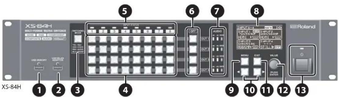
Front Panel/Top Panel/Side Panel
text_image
Multi-Formar Matrix Switches HDMI 1000000000000000000000000000000000000000000000000000000000000000000000000000000000000 COMPOSITE AUDIO 555mm XS-84H 1 2 3 4 5 6 7 8 OUTPUT OUTPUT OUTPUT OUTPUT OUTPUT OUTPUT OUTPUT OUTPUT OUTPUT OUTPUT OUTPUT OUTPUT OUTPUT OUTPUT OUTPUT OUTPUT OUTPUT OUTPUT OUTPUT OUTPUT OUTPUT OUTPUT OUTPUT OUTPUT OUTPUT OUTPUT OUTPUT OUTPUT OUTPUT OUTPUT OUTPUT OUTPUT OUTPUT OUTPUT OUTPUT OUTPUT OUTPUT OUTPUT OUTPUT OUTPUT OUTPUT OUTPUT OUTPUT OUTPUT OUTPUT OUTPUT OUTPUT OUTPUT OUTPUT OUTPUT Output Output Output Output Output Output Output Output Output Output Output| No. Name | Explanation Page | |||
| 1 | USB MEMORY connector | This is for connecting a USB flash drive. You use this when saving or loading settings, or when importing still images. | p. 21p. 27 | |
| 2 | USB WLAN ADAPTOR connector | Here you connect a wireless USB adapter (sold separately) for making a Wi-Fi connection to an iPad.You use this when operating the unit remotely using the XS-80H Remote iPad application.* For the wireless USB adaptor, use the ONKYO UWF-1 or Roland WNA1100-RL. | p. 28 | |
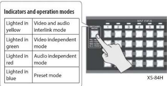
| 3 | [SWITCHING MODE] button | This switches the operation mode of the cross-point selection buttons (4). Successive presses of the button cycle through the modes in this sequence: video and audio interlink mode → video independent mode → audio independent mode → preset mode.The color of the lighted button indicates the operation mode.Lighted in yellow: Video and audio interlink modeLighted in green: Video independent modeLighted in red: Audio independent modeLighted in blue: Preset mode | p. 19p. 27 | |
| 4 | Cross-point selection buttons | These function as follows, according to the operation mode selected using the [SWITCHING MODE] button (3). | p. 19p. 27 | |
| Operation mode Functioning of the cross-point selection buttons | ||||
| Video and audio interlink mode | These switch the cross points for the video or audio channels. According to the operation mode, they can switch the video and audio in tandem, or independently switch only the video or only the audio.Each button's horizontal direction is the input channel and vertical direction is the output channel.The current selection of audio or video channel is indicated by the color of the lighted button. | |||
| Video independent mode | ||||
| Audio independent mode | Lighted in yellow: Video channel and audio channelLighted in green: Video channel onlyLighted in red: Audio channel only | |||
| Preset mode | These function as memory-number selection buttons. These buttons access preset settings that have been saved. | |||
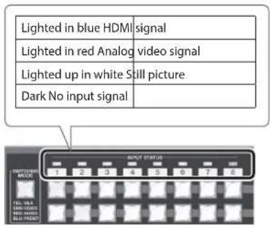
| 5 | INPUT STATUS indicators | These indicate the type of video signal being input.Lighted in blue: HDMI signalLighted in red: Analog video signal (RGB/component, composite, Y/C)Lighted up in white: Still pictureDark: No input signal | p. 19 | |
| 6 | [OFF] buttons | These apply fade to the output video and output a picture of a single color (specifiable). The corresponding [OFF] button lights up when the video fade-out is complete. | p. 24 | |
| 7 | AUDIO level meters | These indicate the volume levels on the output channels. | p. 26 | |
| 8 | Display | These display information about input and output video, menu items, and the like. | p. 18 | |
text_image
Diagram of a server rack with labeled ports and ventilation slots, marked as 14| No. Name | Explanation Page | ||
| 9 | [MENU] button This displays the menu. p. 17 | ||
| 10 | [ cursor) buttons | During menu display, these move the cursor. Also, depending on the menu item, they move to the setting screen for a different channel or the like.These change the view mode for the top screen of the display. | p. 17p. 18 |
| 11 | [EXIT] button | This exits the menus. When the system is at a lower-level menu, these return operation to the upper menu. | p. 17 |
| 12 | [VALUE] knob | This selects menu items and changes setting values. Pressing the [VALUE] dial applies a selected menu item or changes made to a setting value. | p. 17 |
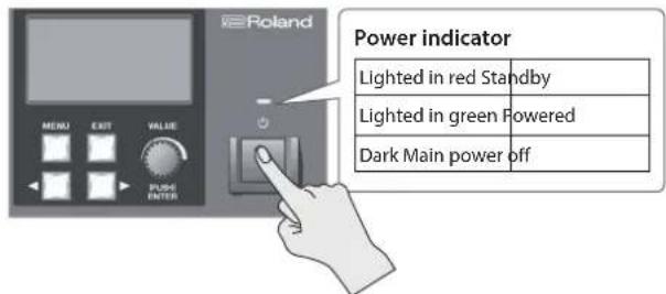
| 13 | Power indicator | This indicates the power state.Lighted in red: StandbyLighted in green: PoweredDark: Main power off | p. 17 |
| Power button | This switches the power between on and standby.* This is enabled only when the [POWER] (main power) switch is set to "ON." | ||
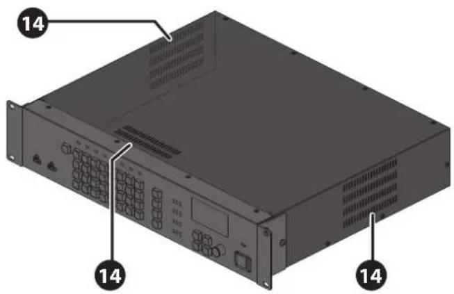
| 14 | Cooling-fan exhaust port | This expels internal heat to keep temperatures inside the unit from rising excessively.NOTENever block the cooling-fan exhaust port. Blocking the exhaust port might result in a rise in temperature inside the unit, resulting in malfunction due to heat. | — |
Rear Panel
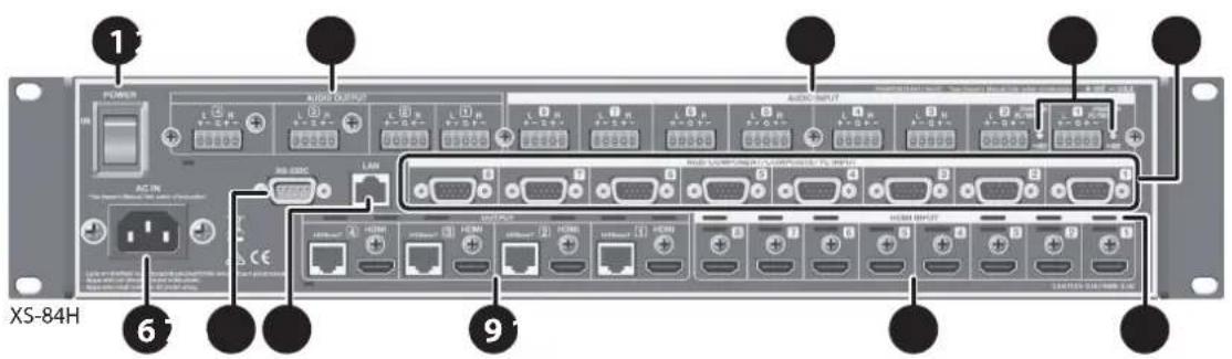
text_image
1 POWER AUDIO OUTPUT AUDIO INPUT AC IN USB-880C LAN USB POWER USB INPUT USB INPUT USB INPUT USB INPUT USB INPUT USB INPUT USB INPUT USB INPUT USB INPUT USB INPUT USB INPUT USB INPUT USB INPUT USB INPUT USB INPUT USB INPUT USB INPUT USB INPUT USB INPUT USB INPUT USB INPUT USB INPUT USB INPUT USB INPUT USB INPUT USB INPUT USB INPUT USB INPUT USB INPUT USB INPUT USB INPUT USB INPUT USB INPUT USB INPUT| No. Name | Explanation Page | ||
| 1 | [POWER] (main power) switch | This turns the main power on and off.When the main power has been turned on, the power button on the front panel can be used to switch the power to on or standby. | p. 17 |
| 2 | AUDIO OUTPUT connectors | These are 5p Euroblock connectors for output of analog audio signals. Recording units, power amps, speakers, and other devices are connected to these.* To make connections, use the included Euroblock plugs (p. 13). | p. 14 |
| 3 | AUDIO INPUT connectors | These are 5p Euroblock connectors for input of analog audio signals. You connect audio decks, microphones, and other such devices to these.* To make connections, use the included Euroblock plugs (p. 13).* AUDIO INPUT connectors 1 and 2 can supply phantom power (+48 V). | p. 14 |
| 4 | Phantom power indicator | This indicator lights up when phantom power (+48 V) is turned on. | p. 14 |
| 5 | Analog video INPUT connectors (RGB/COMPONENT/COMPOSITE/YC INPUT connectors) | These are D-Sub 15-pin connectors for input of analog video signals. In addition to RGB signals, using conversion cables lets you input component, composite, and Y/C (S-Video) signals. You connect video decks, computers, and other such devices to these.* Inputting video requires setting the type of video signal (RGB/component, composite, or Y/C) for each input video channel. | p. 14 |
| 6 | AC IN connector | This is for connecting the included power cord. | p. 16 |
| 7 | RS-232C connector | This is for connecting a remote-control device (such as an RS-232C-compatible computer) for operating the unit remotely. | p. 28 |
| 8 | LAN port | This is for connecting a computer or other network-capable equipment for operating the unit remotely. | p. 28 |
| 9 | HDMI OUTPUT connectors | These output HDMI signals. External displays or other devices equipped with HDMI input connectors are connected to these.* Simultaneously outputting video from both the HDMI output connector and the HDBaseT output connector on the same channel is not possible. | p. 14p. 21 |
| HDBaseT OUTPUT connectors | These output HDBaseT signals. Projectors or other devices equipped with HDBaseT input connectors are connected to these.* To make connections, use a Cat 5e (Category 5e) or later shielded LAN cable. | ||
| 10 | HDMI INPUT connectors | These are for inputting HDMI signals. Video devices equipped with HDMI output connectors are connected to these.* Inputting video requires setting the type of video signal (HDMI) for each input video channel. | p. 15 |
| 11 | Cooling-fan exhaust port | This expels internal heat to keep temperatures inside the unit from rising excessively.NOTENever block the cooling-fan exhaust port. Blocking the exhaust port might result in a rise in temperature inside the unit, resulting in malfunction due to heat. | — |
Important Notes on Rack Mounting
* When mounting the unit in a rack, to ensure efficient cooling, give attention to the following points.
• Install in a well-ventilated location.
- Never obstruct the exhaust ports on the unit's top, rear, and side panels.
- Avoid mounting the unit in a sealed-type rack. Warm air within the rack cannot escape and is sucked into the unit, making efficient cooling impossible.
- If the back of the rack cannot be opened, install an exhaust port or ventilation fan at the top back surface of the rack, where warm air collects.
- When using the unit while mounted in a movable case (portable rack), remove the front and rear rack covers so that the front and back of the unit are not obstructed.
* When installing the unit in a rack or the like, use the mounting screws occupying the screw holes in the rack-mount brackets (included with the unit). Also, use due caution to ensure that your fingers don't get pinched.
* Also read the "Placement" section (p. 9) under "IMPORTANT NOTES."
Attaching the Rubber Feet
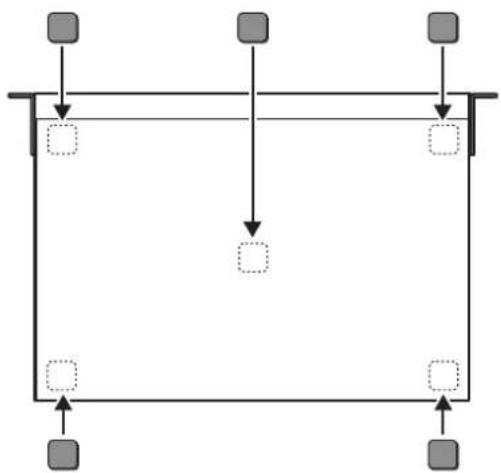
When using the unit with it unmounted in a rack, attach the included rubber feet (5) if necessary.
- Peel off the double-sided tape from the rubber feet and affix the rubber feet at the locations shown in the figure.
flowchart
graph TD
    A["Input 1"] --> B["Process"]
    C["Input 2"] --> D["Process"]
    E["Input 3"] --> F["Process"]
    B --> G["Output 1"]
    D --> H["Output 2"]
    F --> I["Output 3"]
Connecting Cables to the Euroblock Plugs
Attach cables to the included Euroblock plug and connect them to the AUDIO INPUT and OUTPUT connectors.
- Prepare the cables.
Strip off about 5 mm of insulation from the tip of each cable and tightly twist the core wires.
* To avoid electromagnetic noise and other such trouble, we recommend using shielded cables.
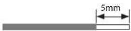
NOTE
Never apply solder to the insulation-stripped section of the cable.
- Attach the cable to the Euroblock plug.
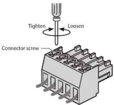
Use a commercially available flathead screwdriver to loosen the connector screw.
Insert the cable prepared in step 1, then secure it in place by tightening the connector screw using the flathead screwdriver.
text_image
Tighten Loosen Connector screwImportant Notes When Wiring
The AUDIO INPUT and OUTPUT connectors are wired as shown in the figure below.
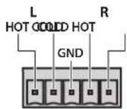
Wire the cables correctly, according to whether you're using balanced or unbalanced connections.
* For information on how to carry out wiring, refer to "AUDIO INPUT/OUTPUT connectors" (p. 33).
- Insert the Euroblock plug into the AUDIO INPUT or OUTPUT connector on the unit.
Connecting External Equipment
* To prevent malfunction and equipment failure, always turn down the volume, and turn off all the units before making any connections.
* Provide cable and adapter plugs to match the connector configuration on the equipment you're using.
Connecting Video Source/Output Equipment
After making the connections, make the settings for the type of incoming video signals on video channels 1 through 8 (p. 19).
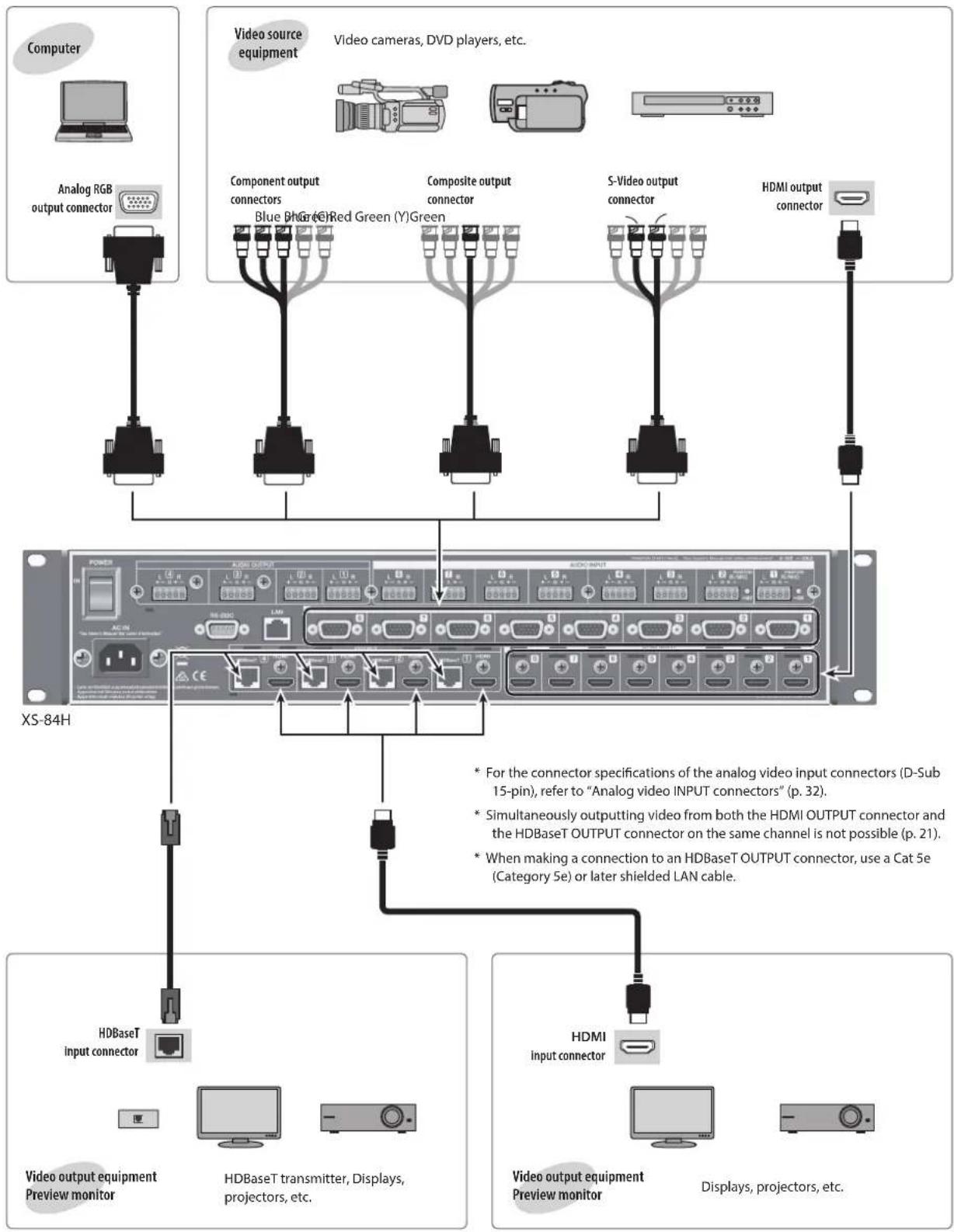
flowchart
graph TD
    A["Computer"] --> B["Analog RGB output connector"]
    C["Video source equipment"] --> D["Component output connectors"]
    C --> E["Blue BHG (6) Red Green (Y) Green"]
    C --> F["Composite output connector"]
    C --> G["S-Video output connector"]
    C --> H["HDMI output connector"]
    I["XS-84H"] --> J["Power"]
    I --> K["HDBaseT input connector"]
    I --> L["Video output equipment Preview monitor"]
    I --> M["HDBaseT transmitter, Displays, projectors, etc."]
    I --> N["HDMI input connector"]
    O["Video cameras, DVD players, etc."] --> P["Component output connectors"]
    O --> Q["Blue BHG (6) Red Green (Y) Green"]
    O --> R["Composite output connector"]
    O --> S["S-Video output connector"]
    O --> T["HDMI output connector"]
    U["* For the connector specifications of the analog video input connectors (D-Sub 15-pin), refer to "Analog video INPUT connectors" (p. 32)."]
    V["* Simultaneously outputting video from both the HDMI OUTPUT connector and the HDBaseT OUTPUT connector on the same channel is not possible (p. 21)."]
    W["* When making a connection to an HDBaseT OUTPUT connector, use a Cat 5e (Category 5e) or later shielded LAN cable."]
    X["Video output equipment Preview monitor"] --> Y["+"]
    Z["Video output equipment Preview monitor"] --> AA["-"]
Connecting Audio Source/Output Equipment
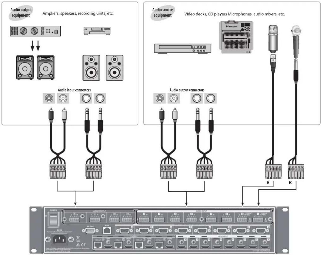
flowchart
graph TD
    A["Audio output equipment"] --> B["Ampliers, speakers, recording units, etc."]
    B --> C["Audio input connectors"]
    D["Audio source equipment"] --> E["Video decks, CD players Microphones, audio mixers, etc."]
    E --> F["Audio output connectors"]
    G["Power"] --> H["AC/DC"]
    H --> I["Switch"]
    I --> J["Switch Input"]
    J --> K["Switch Output"]
    K --> L["Switch Input"]
    L --> M["Switch Output"]
XS-84H
* Connect microphones to the R channel of AUDIO INPUT connector 1 or 2. For information on how to perform wiring, refer to "AUDIO INPUT/OUTPUT connectors" (p. 33).
* AUDIO INPUT and OUTPUT connectors are wired as shown in the figure below. Make connections after first checking the wiring diagrams of other equipment you intend to connect.
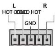
- For information on how to attach cables to the included Euroblock plugs, refer to "Connecting Cables to the Euroblock Plugs" (p. 13).
- For information on how to perform wiring, refer to "AUDIO INPUT/OUTPUT connectors" (p. 33).
* Acoustic feedback could be produced depending on the location of microphones relative to speakers. This can be remedied by:
- Changing the orientation of the microphone(s).
- Relocating microphone(s) at a greater distance from speakers.
- Lowering volume levels
Using Phantom Power
AUDIO INPUT connectors 1 and 2 (R channel only) can supply phantom power (+48 V).
When using a condenser microphone that requires phantom power, turn on phantom power.
[MENU] button → "AUDIO INPUT" → "ANALOG-1" or "ANALOG-2" → set "PHANTOM POWER" to "ON."
The phantom power indicator next to the connector lights up when phantom power is turned on.
NOTE
Always turn the phantom power off when connecting any device other than condenser microphones that require phantom power. You risk causing damage if you mistakenly supply phantom power to dynamic microphones, audio playback devices, or other devices that don't require such power. Be sure to check the specifications of any microphone you intend to use by referring to the manual that came with it. (This instrument's phantom power: 48 V DC, 14 mA Max)
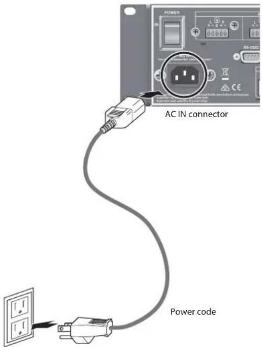
Connecting the Power Cord
NOTE
Be sure to use the included power cord for connecting the power supply.
- Connect the included power cord to the AC IN connector on the rear panel.
text_image
AC IN connector Power code* The shape of the power cord's plug varies depending on the country.
Turning the Power On and Off
Once everything is properly connected (p. 14), be sure to follow the procedure below to turn on their power. If you turn on equipment in the wrong order, you risk causing malfunction or equipment failure.
* Before turning the unit on/off, always be sure to turn the volume down. Even with the volume turned down, you might hear some sound when switching the unit on/off. However, this is normal and does not indicate a malfunction.
* Importing still images (p. 21) might result in longer startup times, depending on the image size and the number saved.
Turning the Power On
- Make sure all devices are turned off.
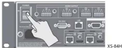
- Turn on the [POWER] (main power) switch on the unit's rear panel.
text_image
POWER RANGE OUTPUT XS-84HThe power indicator on the front panel lights up in red, and the unit goes into standby.
- Press the power button on the unit's front panel to turn on the power.
text_image
Poland MENU EXIT VALUE PULSE ENTER Power indicator Lighted in red Standby Lighted in green Powered Dark Main power offThe power comes on and the color of the lighted power indicator changes to green.
* This unit is equipped with a protection circuit. A brief interval (a few seconds) after turning the unit on is required before it will operate normally.
- Turn on the power to the source devices.
Turn on the power to source equipment connected to input connectors on the unit.
- Turn on the power to the output devices.
Turn on the power to projectors or other devices connected to output connectors on the unit.
Turning the Power Off
-
Turn off the power first to output equipment, and then to source equipment.
-
If the unit's power is on, press the power button once more.
The color of the lighted power indicator changes from green to red, and the unit goes into standby.
- Turn off the [POWER] (main power) switch on the rear panel.
The power indicator goes dark and the power is turned off.
* If you need to turn off the power completely, first turn off the unit, then unplug the power cord from the power outlet. Refer to "To completely turn off power to the unit, pull out the plug from the outlet" (p. 5).
Using the Menus
This explains how to display menus and make various settings
MEMO
For more information about the menus, download and refer to the Reference Manual (PDF) for the unit from the following Roland website.
https://proav.roland.com/manuals/
- Press the [MENU] button to display the menu.
The menu categories are displayed.
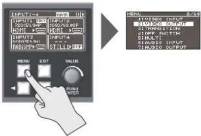
text_image
INPUT 1 720/53.94F HDMI INPUT 2 180/65.94F HDMI INPUT 3 180/65.94F HDMI OUTPUT 4 STILLI MENU EXIT VALUE PUSH INTER MENU 15 VINES INPUT 25 VINES OUTPUT 35 VINES INPUT 45 VINES OUTPUT 5 VINES INPUT 6 VINES OUTPUT 7 VINES OUTPUT- Turn the [VALUE] dial to select a category, then press the [VALUE] dial to confirm the selection.
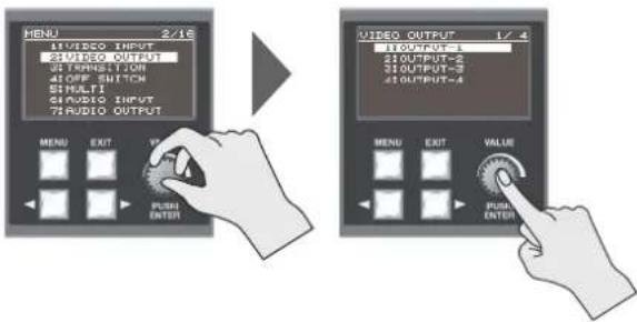
text_image
MENU 2/16 21VIDEO OUTPUT 32TRANSITION 41OFF SWITCH SIMULI 53AUDIO INPUT 73AUDIO OUTPUT MENU EXIT VS PUSH ENTER VIDEO OUTPUT 1/4 11OUTPUT-1 21OUTPUT-2 31OUTPUT-3 41OUTPUT-4 MENU EXIT VALUE PUSH ENTERThe menu items for the selected category are displayed.
- Turn the [VALUE] dial to select a menu item, then press the [VALUE] dial to confirm the selection.
- If the menu item is located at a deeper level, repeat step 3.
-
Turn the [VALUE] dial to change the setting value.
-
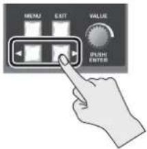
If there is more than one setting location, use the cursor buttons to move the cursor, then change the setting.
- You can use the cursor buttons to jump to the setting screen for a different channel or the like, without having to go back up one level.
-
You can change the setting value in larger steps by holding down the [VALUE] dial as you turn it.
-
Press the [MENU] button to quit the menu.
Pressing the [EXIT] button once returns you to the previous screen.
MEMO
You can return the menu item you're setting to its factory-default value by holding down the [VALUE] knob and pressing the [EXIT] button.
Changing the View on the Display
The unit's top screen has five types of view modes.
You use the cursor buttons to change the view mode.
text_image
MEANJ EXIT VALUE PUSHI ENTERInput/output status screen
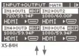
text_image
INPUT→OUTPUT MATR IN1→OUT1 HDCF IN2→OUT2 720/59.94P 1080/60.00P HDMI HDMI IN4→OUT3 HDCF IN3→OUT4 HDCF 1080/59.94P 1080/59.94P HDMI HDMI XS-84HThis displays information about the currently selected video input and output channels.
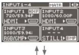
Input status screen 1/2
text_image
INPUT1-4 INPUT1 HDCP 720/59.94P HDMI ► INPUT2 1080/60.00P HDMI ► INPUT3 1080/59.94i RGB/GMP► INPUT4 STILL1 BMPThis displays information about video input channels 1 through 4.
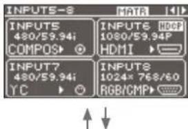
Input status screen 2/2
text_image
INPUTS-8 DATA 14 INPUTS 480/59.94i COMPOS INPUTS HDCE 1080/59.94P HDMI INPUTS 480/59.94i YC INPUTS 1024* 768/60 RGB/CMPThis displays information about video input channels 5 through 8.
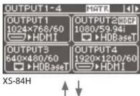
Output status screen
text_image
OUTPUT1-4 OUTPUT1 1024×768/60 HDMI OUTPUT2HDB 1080/59.94i HDBaseT OUTPUT3 640×480/60 HDBaseT OUTPUT4 1920×1200/60 HDMI XS-84HThis displays information about the video output channels.
Audio volume control screen
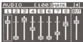
This displays audio faders for eight audio input channels and one output channel.
You operate the audio faders to adjust the volume levels for audio input and output (p. 25, p. 26).
* You can change the audio input channels and output channel assigned to the audio faders as required. For details, refer to "Changing Audio Fader Assignments" in the column at right.
MEMO
- You can adjust the brightness of the display. Use the [MENU] button → "SYSTEM" → "LCD BACKLIGHT" to adjust.
- You can set the view mode of the display at startup by using the [MENU] button "SYSTEM" "TOP DISPLAY."
Changing Audio Fader Assignments
At the audio volume control screen, you can display audio faders for eight audio input channels and one audio output channel. You can change the audio input channels and output channel assigned to the audio faders as required.
Assigning an Audio Input Channel
- Use the [MENU] button → "AUDIO CONTROL" → "FADER 1" through "FADER 8" to select the audio input channel to assign to the respective audio fader.
You can choose from among "HDMI INPUT 1" through "HDMI INPUT 8" and "ANALOG INPUT 1" through "ANALOG INPUT 8."
- Press the [MENU] button to quit the menu.
Assigning an Audio Output Channel
- Use the [MENU] button → "AUDIO CONTROL" → "OUTPUT FADER" to select the audio output channel to assign to the audio fader.
You can choose from among "OUTPUT 1" through "OUTPUT 4" (Note: This varies according to the model.), or "ALL." Selecting "ALL" makes it possible to adjust the audio on all audio output channels simultaneously.
- Press the [MENU] button to quit the menu.
Setting the Video Signal for Each Video Input Channel
This sets the type of incoming video signal for each individual video input channel.
NOTE
No video is output if the type setting for the input video signal is incorrect.
MEMO
You can assign a still image imported from a USB flash drive to a video input channel and output it in the same way as video. For details, refer to "Outputting an Imported Still Image" (p. 21).
-
Use the [MENU] button → "VIDEO INPUT" → "INPUT-1" through "INPUT-8" → "INPUT SELECT" to make your selection.
-
Turn the [VALUE] dial to select the video signal.
-
If you want to output a still image imported into the unit, choose "STILL1" through "STILL4 (p. 21).
-
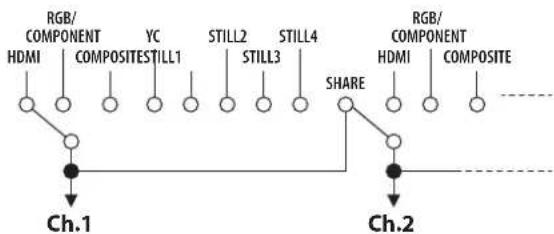
Selecting "SHARE" enables sharing of a video source on the video input channels. For details, refer to the column below, "Sharing a Video Source (SHARE)."
-
Press the [MENU] button to quit the menu.
MEMO
When video is input, the INPUT STATUS indicator lights up.
text_image
Lighted in blue HDMI signal Lighted in red Analog video signal Lighted up in white Still picture Dark No input signalSharing a Video Source (SHARE)
You can share a video source on the video input channels. Sharing a video source assigns a single video source to two or more input channels.
The video source you can share on video input channels is the source on the previous channel. For example, to share the video on channel 1 on channels 2 through 8, set "INPUT SELECT" for channels 2 to 8 to "SHARE."
flowchart
graph TD
    A["Ch.1"] --> B["RGB/COMPONENT HDMI"]
    A --> C["COMPOSITE YC"]
    A --> D["STILL1"]
    A --> E["STILL2"]
    A --> F["STILL3"]
    A --> G["STILL4"]
    H["Ch.2"] --> I["RGB/COMPONENT HDMI"]
    H --> J["COMPOSITE"]
    H --> K["SHARE"]
    style A fill:#f9f,stroke:#333
    style H fill:#f9f,stroke:#333
    style I fill:#f9f,stroke:#333
    style J fill:#f9f,stroke:#333
* Audio sources cannot be shared.
Changing Cross Points
This changes the cross points for video or audio.
* This unit provides a variety of output modes for video output. The explanation in this section describes the procedure for changing the cross point when the output mode is set to "MATRIX." For information on how to set the output mode, refer to "Switching the Video Output Mode" (p. 22).
- Use the [MENU] button → "TRANSITION" → "TIME" to set the length of the video transition (0.0 to 10.0 sec).
When you want an instant video transition, set the value to "0.0 sec." * The "TIME" setting is shared with the fade time (p. 24).
- Press the [SWITCHING MODE] button to change the operation mode of the cross-point selection buttons.
text_image
Indicators and operation modes Lighted in yellow Video and audio interlink mode Lighted in green Video independent mode Lighted in red Audio independent mode Lighted in blue Preset mode X5-84HSuccessive presses of the [SWITCHING MODE] button cycle through the modes in this sequence: video and audio interlink mode → video independent mode → audio independent mode → preset mode.
NOTE
When the [SWITCHING MODE] button is lighted up in blue (preset mode), the cross-point selection buttons function as memory-number selection buttons (p. 27).
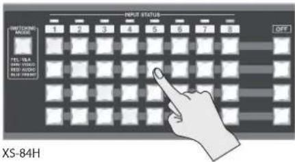
- Press a cross-point selection button.
text_image
NPKR STATUS 1 2 3 4 5 6 7 8 OFF SWITCHING NAME TEL TRA SPIN VERSIC RED AUDIO BLUE CHIP XS-84HEach button's horizontal direction is the input channel and vertical direction is the output channel.
The cross point of the audio or video channel is switched according to the operation mode you selected in step 2.
The current selection of audio or video channel is indicated by the color of the lighted button.
• Lighted in yellow: Video channel and audio channel
• Lighted in green: Video channel only
•Lighted in red: Audio channel only
MEMO
You can change the fade color used during the video transition. Use the [MENU] button → "OFF SWITCH" → "RED," "GREEN," or "BLUE" to adjust the color. The setting for fade color is shared with fades (p. 24).
Inputting/Outputting Copyright-protected (HDCP) Video
This unit lets you enable and disable HDCP (digital content protection) individually for copyright-protected (HDCP) video that is input and output. By default, input and output of HDCP-protected video are enabled. To enable or disable HDCP input and output, use the procedure described below to describe below to change the setting.
Input
- Use the [MENU] button → "VIDEO INPUT" → "INPUT-1" through "INPUT-8" → "HDCP INPUT ENABLE" to make the setting.
| Setting value | Description |
| ENABLE Copyright-protected (HDCP) video can be input. | |
| DISABLE Copyright-protected (HDCP) video cannot be input. | |
- Press the [MENU] button to quit the menu.
NOTE
When inputting or outputting video on which no copyright protection (HDCP) is applied, the effects of HDCP on other channels might result in no audio output.
For details, refer to "Important Notes When Working with Copyright-protected (HDCP) Video" in the Reference Manual (PDF).
Output
- Use the [MENU] button → "VIDEO OUTPUT" → "OUTPUT-1" through "OUTPUT-4" (Note: This varies according to the model.) → "HDCP OUTPUT ENABLE" to make the setting.
| Setting value | Description |
| ENABLE | Video is output with copyright protection (HDCP) applied.HDCP is applied even to output video that is notcopyright-protected (HDCP). |
| DISABLE | Video is output with no copyright protection (HDCP) applied.* Copyright-protected (HDCP) video cannot be outputwith no HDCP applied. When the setting is at “DISABLE,”a black video image is output. |
- Press the [MENU] button to quit the menu.
Checking HDCP-compatible Equipment
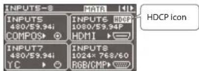
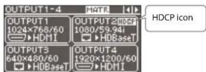
When the setting for HDCP-applied input or output is at "ENABLE," you can use the output status view or input status view on the display to check the state of HDCP compatibility of connected equipment.
Input status screen
The HDCP icon is displayed when copyright-protected (HDCP) video is input.
text_image
INPUTS-8 INPUTS 480/59.94i COMPOS INPUTS 480/59.94i YC INPUTS 1024× 768/60 RGB/CMP INPUTS HDCP 1080/59.94P HDMI INPUTS HDCP iconOutput status screen
The HDCP icon is displayed when HDCP-compatible equipment is connected.
text_image
OUTPUT1-4 HATR OUTPUT1 1024×768/60 HDMI OUTPUT2 1080/59.94 HDBaseT OUTPUT3 640×480/60 HDBaseT OUTPUT4 1920×1200/60 HDMI HDCP iconXS-84H
Switching Between HDMI Output and HDBaseT Output
By factory default, the selection of HDMI output and HDBaseT output is set at "AUTO" (the setting for automatic detection on connection). When devices are connected to both the HDMI OUTPUT connector and the HDBaseT OUTPUT connector, HDMI output takes precedence.
When you want to output video via a specified OUTPUT connector, change the setting.
NOTE
Simultaneously outputting video from both the HDMI OUTPUT connector and the HDBaseT OUTPUT connector on the same channel is not possible.
- Use the [MENU] button → "VIDEO OUTPUT" → "OUTPUT-1" through "OUTPUT-4" (Note: This varies according to the model.) → "OUTPUT SELECT" to make the setting.
| Setting value | Description |
| AUTO | The connector where the connection is made is automatically detected and video is output.When devices are connected to both the HDMI OUTPUT connector and the HDBaseT OUTPUT connector, HDMI output takes precedence. |
| HDMI Video is | output only from the HDMI OUTPUT connector. |
| HDBaseT | Video is output only from the HDBaseT OUTPUT connector. |
- Press the [MENU] button to quit the menu.
Outputting an Imported Still Image
This assigns a still image imported from a USB flash drive to a video input channel and outputs it in the same way as video.
Supported Still-image Formats and Resolutions
Still-image file formats that can be imported are as follows.
| Format Bitmap (.bmp), 24-bit, uncompressed |
| Resolution Maximum 1,920 x 1,200 pixels |
NOTE
Still images cannot be scaled. Provide a still image whose resolution matches the final format.
Importing a Still Image
This imports into the unit a still image saved on a USB flash drive. You can save four still images in the unit.
* When you're using a USB flash drive for the first time, be sure to format it on the unit (p. 28).
- Save the still image in the root directory of the USB flash drive.
Give the still image a file name composed of no more than eight alphanumeric characters, and be sure to append a ".bmp" file extension. - Connect the USB flash drive containing the saved still image to the USB MEMORY connector.
- Select the [MENU] button → "USB MEMORY" → "LOAD STILL IMAGE" → the destination for saving the still image (1 through 4), then press the [VALUE] dial.
The "LOAD STILL IMAGE" popup appears. The names of the files on the USB flash drive are displayed in the popup. - Select the still image file you want to import, then press the [VALUE] dial.
- Check the message and press the [VALUE] dial. (If you want to quit, press the [EXIT] button.) The still image is imported into the unit
- Press the [MENU] button to quit the menu.
NOTE
Importing still images might result in longer startup times, depending on the image size and the number saved.
Outputting a Still Image
This outputs the still image imported into the unit.
- Assign the still image to a video input channel.
Follow the procedure in "Setting the Video Signal for Each Video Input Channel" (p. 19), and at step 2, select "STILL1" through "STILL4." - Press the cross-point selection button for the video input channel where "STILL1" through "STILL4" is assigned (p. 19). The still image is output.
Switching the Video Output Mode
This unit provides a variety of output modes for video output. Selecting an output mode recalls preset values for video output.
* You can change "VIDEO OUTPUT" settings after recalling the preset values for video output. Note, however, that depending on the "MODE" setting, some individual menu items might be unchangeable.
For details, refer to "VIDEO OUTPUT" under "Menu List" in the Reference Manual (PDF).
1. Select the [MENU] button → "MODE" → the output mode.
In this section, output images are described using A through H for the input video and 1 through 4 for the output video, as shown in the figure at right.
![ROLAND XS-84H - Select the [MENU] button → "MODE" → the output mode. - 1](/content/2026/05/798330/images/240ad33714a093600b041808420582a16def7735156c03468eccf0bb4594b1c1.jpg)
text_image
INPUT ABCDE F GH OUTPUT 1 2 3 4 XS-84H| Setting value Description | Output image Interlinked buttons | |||||||||
| OUTPUT 1 OUTPUT 2 OUTPUT 3 OUTPUT 4 OUTPUT | Button illumination pattern | |||||||||
| 1 2 | 3 4 | |||||||||
| MATRIX | This outputs the video input channels selected using the cross-point selection buttons (p. 19). | ![ROLAND XS-84H - Select the [MENU] button → "MODE" → the output mode. - 2](/content/2026/05/798330/images/6b2309549a78729df4d92eaec44903d6dfac405d985136633ca6a1c234940dae.jpg) | ![ROLAND XS-84H - Select the [MENU] button → "MODE" → the output mode. - 3](/content/2026/05/798330/images/0319be6a3e007f206d62330b492343a71eedc96881fda33b21112731ba70b1a3.jpg) | ![ROLAND XS-84H - Select the [MENU] button → "MODE" → the output mode. - 4](/content/2026/05/798330/images/8272faa06bbd648765ca621899e2ad6f8b87d004cb2c7cc7be1e2d582bc6635e.jpg) | ![ROLAND XS-84H - Select the [MENU] button → "MODE" → the output mode. - 5](/content/2026/05/798330/images/4b3c74f60efc03705618c2c80d292b26cfdca24f054e26a16bfd82ea3c90ab28.jpg) | ![ROLAND XS-84H - Select the [MENU] button → "MODE" → the output mode. - 6](/content/2026/05/798330/images/d6369052c92465ecf54cd872290bb202f78a09a664489646c6cfea36c982f6ab.jpg) | ||||
| MULTI-2 (*1) | This combines video pictures into composite output. The layer positions are fixed and cannot be changed. ![ROLAND XS-84H - Select the [MENU] button → "MODE" → the output mode. - 7](/content/2026/05/798330/images/c9d8dfe18d01df60cd85afe2086f6b5f82c1283ff0ae88947d194c87c1838998.jpg) | ![ROLAND XS-84H - Select the [MENU] button → "MODE" → the output mode. - 8](/content/2026/05/798330/images/844ccf92c1d0c55a7638cd94b31adcaec9d9f7e976b0c581add6257c31dafc46.jpg) | ![ROLAND XS-84H - Select the [MENU] button → "MODE" → the output mode. - 9](/content/2026/05/798330/images/7c1a181e0b8e8ef3c147d9ddc499f1b547355510924db128a3db0ac34eb5d317.jpg) | ![ROLAND XS-84H - Select the [MENU] button → "MODE" → the output mode. - 10](/content/2026/05/798330/images/bbc8e72de69bb77e5cd78e6d1f1c92ab92e7d8c3a174f00cecd5c42a1af52fbb.jpg) | ![ROLAND XS-84H - Select the [MENU] button → "MODE" → the output mode. - 11](/content/2026/05/798330/images/d4c2fc6244516effb318a7eafe1f2d6d7ebe64e6775f4e15f5b2a8f4c27f3ce9.jpg) | |||||
| MULTI-3 (*1) | ![ROLAND XS-84H - Select the [MENU] button → "MODE" → the output mode. - 12](/content/2026/05/798330/images/2a170fe1d92d6d32257c74775ab5bfc3b154f9233ab7da3cfd098c3c6ad739a5.jpg) | ![ROLAND XS-84H - Select the [MENU] button → "MODE" → the output mode. - 13](/content/2026/05/798330/images/99a5285074414eca1e3e59e55fa1cbe9468fd8ff26107fa1bbef06905a3e3630.jpg) | ![ROLAND XS-84H - Select the [MENU] button → "MODE" → the output mode. - 14](/content/2026/05/798330/images/e6944821a2dda9a09d86b2b6289b05dcca267e4104ccaa6a3a3f8595d30b0999.jpg) | ![ROLAND XS-84H - Select the [MENU] button → "MODE" → the output mode. - 15](/content/2026/05/798330/images/fecebdefca153c692bdc438a8bd984f026b471fc39cb65a98000aa64d6b2b71f.jpg) | ![ROLAND XS-84H - Select the [MENU] button → "MODE" → the output mode. - 16](/content/2026/05/798330/images/239f32959c1ee9f5033779b19ac9c9d101655551769ea94d8d7d339d50069c75.jpg) | |||||
| MULTI-4 (*1) | ![ROLAND XS-84H - Select the [MENU] button → "MODE" → the output mode. - 17](/content/2026/05/798330/images/8bd2a972f9061ebe326d4f9c0d00b7a0ba8daebd73261d2d30ce53916bae5406.jpg) | ![ROLAND XS-84H - Select the [MENU] button → "MODE" → the output mode. - 18](/content/2026/05/798330/images/2fd8a57ef0dfd3fcfd4eca9b370dce337a41d0cbc0ad741a249e0f51a7d946ef.jpg) | ![ROLAND XS-84H - Select the [MENU] button → "MODE" → the output mode. - 19](/content/2026/05/798330/images/4bac9c1cff71385ca8524d399f9a7267448f2fc5f14fed27d970045c153384b3.jpg) | ![ROLAND XS-84H - Select the [MENU] button → "MODE" → the output mode. - 20](/content/2026/05/798330/images/c93052122ec9011ad710b5b31343e082bd8909e3f6976804bee6507fa3bb13e1.jpg) | ![ROLAND XS-84H - Select the [MENU] button → "MODE" → the output mode. - 21](/content/2026/05/798330/images/edc39db0c6d867a3d159b8fc66fbcb77bd8d689a65f60e3f0946abb3749b37be.jpg) | |||||
| SPAN-2 | This displays a single video picture across multiple screens. | ![ROLAND XS-84H - Select the [MENU] button → "MODE" → the output mode. - 22](/content/2026/05/798330/images/ec8c205375c6b0fdf4b2adfcedabd8fd8d2eb42c8b05c0293fb01e637b141cc1.jpg) | ![ROLAND XS-84H - Select the [MENU] button → "MODE" → the output mode. - 23](/content/2026/05/798330/images/f6a97dabf6947d6ff3ee5c350a45715ab4fe2106bb3cd66e1904835b35536cb9.jpg) | ![ROLAND XS-84H - Select the [MENU] button → "MODE" → the output mode. - 24](/content/2026/05/798330/images/7db2eeddedf0152fdc2f60ff2c75a77c5b049e3b2a3126e9ccb8c1fbb425c07e.jpg) | ![ROLAND XS-84H - Select the [MENU] button → "MODE" → the output mode. - 25](/content/2026/05/798330/images/fddb4224d78f0ec36ca180633c2a53964580865895181d99f649b82ecc9b7cca.jpg) | ✓ | ✓ | ![ROLAND XS-84H - Select the [MENU] button → "MODE" → the output mode. - 26](/content/2026/05/798330/images/12257e9ab1bf0d36d87a70710f005987e0001e7f7905facb56f029e47fb20324.jpg) | ||
| SPAN-3 (*2) | ![ROLAND XS-84H - Select the [MENU] button → "MODE" → the output mode. - 27](/content/2026/05/798330/images/b5ac36cc41d7bfaf9c6b97c7f2f5d3231ba5671a1b0c977669c46cd3fb547d7c.jpg) | ![ROLAND XS-84H - Select the [MENU] button → "MODE" → the output mode. - 28](/content/2026/05/798330/images/55114868c822dc1fd11acbf714fbd6347ace8a4b1997998b7f8bd36477d071d4.jpg) | ![ROLAND XS-84H - Select the [MENU] button → "MODE" → the output mode. - 29](/content/2026/05/798330/images/722a8dfff133b06476cf13fa3cef5cffa1b63d4eaa7602073562603baeb6b91e.jpg) | ![ROLAND XS-84H - Select the [MENU] button → "MODE" → the output mode. - 30](/content/2026/05/798330/images/eb4c0984f76ed4f9f391ec3c27acdb42dfe8d4ffabef962642578d306e003a74.jpg) | ✓✓✓ | ![ROLAND XS-84H - Select the [MENU] button → "MODE" → the output mode. - 31](/content/2026/05/798330/images/03e464021c9368c02c95a9ecc35e2e5c293c8084fe95354ec30b67ee87c8a9b3.jpg) | ||||
| SPAN-4 (*3) | ![ROLAND XS-84H - Select the [MENU] button → "MODE" → the output mode. - 32](/content/2026/05/798330/images/bfe57d25a35d74a6f9bfd45cf889b3f7e2fead34f44907fb0e6c93a005afff7e.jpg) | ![ROLAND XS-84H - Select the [MENU] button → "MODE" → the output mode. - 33](/content/2026/05/798330/images/299c8b5ec54c74d738f262d6c51f1a36741ba8f1a58a34c138db2a018835abf6.jpg) | ![ROLAND XS-84H - Select the [MENU] button → "MODE" → the output mode. - 34](/content/2026/05/798330/images/9d75c0c5446ebb5a2bad5a22aea1be4408a72bac998161c9fb48b487349102b5.jpg) | ![ROLAND XS-84H - Select the [MENU] button → "MODE" → the output mode. - 35](/content/2026/05/798330/images/e21a089bf51a4b48a36d1be8d20a31b3062e291927a48aead5bc5e147330f75a.jpg) | ✓✓✓✓ | ![ROLAND XS-84H - Select the [MENU] button → "MODE" → the output mode. - 36](/content/2026/05/798330/images/e12dc2ec8121e924882f7b1abc2e87b490d88c4f4a9dbaf617e6cc4a8acf1a6d.jpg) | ||||
| ROTATION-L1 | This outputs the picture rotated 90 degrees counterclockwise. | ![ROLAND XS-84H - Select the [MENU] button → "MODE" → the output mode. - 37](/content/2026/05/798330/images/a80b69e48ad3fc427885cbad3b0ee09f17fc8e3e52fd9199f5b95a16f9cb4a68.jpg) | ![ROLAND XS-84H - Select the [MENU] button → "MODE" → the output mode. - 38](/content/2026/05/798330/images/25d809c6547d97e0106c3a43f728d62b5e480413c41d1ab1763ac2bbbcd81659.jpg) | ![ROLAND XS-84H - Select the [MENU] button → "MODE" → the output mode. - 39](/content/2026/05/798330/images/245711049d12087340d32c1a88220179cc59d95bbc226b8dc71de2e5c8ee6535.jpg) | ![ROLAND XS-84H - Select the [MENU] button → "MODE" → the output mode. - 40](/content/2026/05/798330/images/f0a070c92e09fe12113675f76d0058bd6d5e1ab958edf3c2be1fb2328fd5b43e.jpg) | ✓✓✓✓ | ||||
| ROTATION-L2 | ![ROLAND XS-84H - Select the [MENU] button → "MODE" → the output mode. - 41](/content/2026/05/798330/images/45adf37c1466f29089dcd0cb5dbef243ed940759b8cf4587ed9e0d433fdda6eb.jpg) | ![ROLAND XS-84H - Select the [MENU] button → "MODE" → the output mode. - 42](/content/2026/05/798330/images/42e1b67fef08657291e3be08bc8cdda81bf2998ad22e069631cc1ae6d8798b43.jpg) | ![ROLAND XS-84H - Select the [MENU] button → "MODE" → the output mode. - 43](/content/2026/05/798330/images/945e6f790744e1262f06e9b1c4cb1d61de9443d42a5bd8099ceae8e4ca712285.jpg) | ![ROLAND XS-84H - Select the [MENU] button → "MODE" → the output mode. - 44](/content/2026/05/798330/images/6bdd62b326efef5388e497b252b509198c680b89f58a5975d89b8f28aad1546f.jpg) | ✓✓✓✓ | |||||
| ROTATION-L3 (*2) | ![ROLAND XS-84H - Select the [MENU] button → "MODE" → the output mode. - 45](/content/2026/05/798330/images/d676591b3ead3de15a24840643038b2eeb4107b4adc30c87bfb25f231521d03b.jpg) | ![ROLAND XS-84H - Select the [MENU] button → "MODE" → the output mode. - 46](/content/2026/05/798330/images/573ad97bf900aa1955728e203fc71867fd87ef0919ef84f519022d373463c312.jpg) | ![ROLAND XS-84H - Select the [MENU] button → "MODE" → the output mode. - 47](/content/2026/05/798330/images/16a356fd3eea06633dc689d89d7247b84ba8abbe97a0e24a9f18d4719248c08c.jpg) | ![ROLAND XS-84H - Select the [MENU] button → "MODE" → the output mode. - 48](/content/2026/05/798330/images/04689ceec66840516f79d03490d51e330c0780c771ecacdc6f092c833563c445.jpg) | ✓✓✓✓ | |||||
| ROTATION-L4 (*3) | ![ROLAND XS-84H - Select the [MENU] button → "MODE" → the output mode. - 49](/content/2026/05/798330/images/f2ab625ae84722487e6fb055bf4ab6b9c7275580b2e750e49888b74e50f81c50.jpg) | ![ROLAND XS-84H - Select the [MENU] button → "MODE" → the output mode. - 50](/content/2026/05/798330/images/1c41edb3659f2ebdf3d13eb214a5548e44a43556a23293e0647d6484432786ac.jpg) | ![ROLAND XS-84H - Select the [MENU] button → "MODE" → the output mode. - 51](/content/2026/05/798330/images/11f3531047fe7a2e8c683b765c90d30bef9bc824055ceee12b0595b068a405a8.jpg) | ![ROLAND XS-84H - Select the [MENU] button → "MODE" → the output mode. - 52](/content/2026/05/798330/images/e3557f7821b3c4e0f8541ecfbd6a0ee78eb79a633a1542e19b8e9bc04f9a7ac3.jpg) | ✓✓✓✓ | |||||
| ROTATION-R1 | This outputs the picture rotated 90 degrees clockwise. | ![ROLAND XS-84H - Select the [MENU] button → "MODE" → the output mode. - 53](/content/2026/05/798330/images/a9af2d6ef745295caf8292c8a0b97e02d5f024abc528409acf4db27a5568d9f7.jpg) | ![ROLAND XS-84H - Select the [MENU] button → "MODE" → the output mode. - 54](/content/2026/05/798330/images/5bcb7b0c15e1b7248d437dde3801e2bb8919da82b57dc494f5f167acde587e3d.jpg) | ![ROLAND XS-84H - Select the [MENU] button → "MODE" → the output mode. - 55](/content/2026/05/798330/images/f34e2e6b153086352f5c98d17235c1fbca7ff32cc7d6475182c9b81bf7d24c63.jpg) | ![ROLAND XS-84H - Select the [MENU] button → "MODE" → the output mode. - 56](/content/2026/05/798330/images/edde9cf62bf453b5cef64f15feaf00fed2ecb24763efc13937b790c287510fd4.jpg) | ✓✓✓✓✓ | ||||
| ROTATION-R2 | ![ROLAND XS-84H - Select the [MENU] button → "MODE" → the output mode. - 57](/content/2026/05/798330/images/65605f8e68f4a8b008401deacc1677146aae3a4a1ccf70b7b30d59d1e8b4fb9e.jpg) | ![ROLAND XS-84H - Select the [MENU] button → "MODE" → the output mode. - 58](/content/2026/05/798330/images/29d488dfe4f30dfeaac472487a6b6aa45113535fdc2c5e55f89eb2d79a6f98bf.jpg) | ![ROLAND XS-84H - Select the [MENU] button → "MODE" → the output mode. - 59](/content/2026/05/798330/images/eb004600735461a2b13b276dadab25ab3be44534382f3c53df130b6625d69849.jpg) | ![ROLAND XS-84H - Select the [MENU] button → "MODE" → the output mode. - 60](/content/2026/05/798330/images/d340e81afa1de8f9c7e5a272aa584a46b743296eff90359d72869251dbe38e7e.jpg) | ✓✓✓✓✓ | |||||
| ROTATION-R3 (*2) | ![ROLAND XS-84H - Select the [MENU] button → "MODE" → the output mode. - 61](/content/2026/05/798330/images/bca6a330dc85e8741d97c116ecc0ade3b87f66fee77003e0c7fdad7825674267.jpg) | ![ROLAND XS-84H - Select the [MENU] button → "MODE" → the output mode. - 62](/content/2026/05/798330/images/b83ce1e958411f81ac1d4dd0ee74570deac74a4e5c2c4d5f6fdcc55b1be12215.jpg) | ![ROLAND XS-84H - Select the [MENU] button → "MODE" → the output mode. - 63](/content/2026/05/798330/images/f3239e46b049ad0e6936d962e0201e6fe714d0851e75568c8623c992f3fb56b9.jpg) | ![ROLAND XS-84H - Select the [MENU] button → "MODE" → the output mode. - 64](/content/2026/05/798330/images/e7ddae7c71231998a0133afc492e180fbe4c735a898b6fd9c0c6589dae819b53.jpg) | ✓✓✓✓✓ | |||||
| ROTATION-R4 (*3) | ![ROLAND XS-84H - Select the [MENU] button → "MODE" → the output mode. - 65](/content/2026/05/798330/images/b56afedf8913fa18900db2913378fa6393157322cfda8828fda52c9cc0ff1582.jpg) | ![ROLAND XS-84H - Select the [MENU] button → "MODE" → the output mode. - 66](/content/2026/05/798330/images/f50071d4092bda4f68bf849e1286ef3ceee032e44cbbe6df7b73180c73d66c3e.jpg) | ![ROLAND XS-84H - Select the [MENU] button → "MODE" → the output mode. - 67](/content/2026/05/798330/images/0e0435f5483c8c28b4c865f4f3ffd24341a101524d702ca612fd40df9cd0878c.jpg) | [8YSK] | ✓✓✓✓✓ | |||||
| 4K-1 (*3) | Pressing the cross-point selection buttons switches video output channels 1 through 4 simultaneously.Video input channel 1 through 4 and 5 through 8 are respectively grouped together as a set, and regardless of which cross-point selection button is pressed, the cross-point selection buttons are automatically selected as shown in the figure at right. | ![ROLAND XS-84H - Select the [MENU] button → "MODE" → the output mode. - 68](/content/2026/05/798330/images/f05dd8f6d4ba8657a83780d0e04272cc1e52d4bcbb066fce1cf680deea1ad031.jpg) ![ROLAND XS-84H - Select the [MENU] button → "MODE" → the output mode. - 69](/content/2026/05/798330/images/8040a6bb8084d73f8c1823a8eb2e93b801a831d2d212886bffa8b95dc3a379b4.jpg) | ![ROLAND XS-84H - Select the [MENU] button → "MODE" → the output mode. - 70](/content/2026/05/798330/images/59ee7fa11119e9713c19ec710610b82663e74a1af4c0576c75536c454f97976b.jpg) | OUTPUT 2OUTPUT 4 | ✓✓✓✓✓ | |||||
![ROLAND XS-84H - Select the [MENU] button → "MODE" → the output mode. - 71](/content/2026/05/798330/images/977dd7de78163fdeea91b55dac4cac9b84e5b374353122c6cdae3fe7f68ca073.jpg) ![ROLAND XS-84H - Select the [MENU] button → "MODE" → the output mode. - 72](/content/2026/05/798330/images/9cfbe82a063485dc972f691e26ad32c86ef71bf9d4886ba11e45e3d09036a040.jpg) | ![ROLAND XS-84H - Select the [MENU] button → "MODE" → the output mode. - 73](/content/2026/05/798330/images/8b8b9076e38f17252961598af413a58a2bc4312543be14c0c9544d87988f477b.jpg) | OUTPUT 2OUTPUT 4 | ✓✓✓✓✓ | |||||||
| 4K-2 (*3) | •Video input channels 1 - 4Operation is the same as for 4K-1. | ![ROLAND XS-84H - Select the [MENU] button → "MODE" → the output mode. - 74](/content/2026/05/798330/images/e33a8cfb1ed8e855e0a50af0614abf35d728c13577e3b39e3853092cc389a89d.jpg) ![ROLAND XS-84H - Select the [MENU] button → "MODE" → the output mode. - 75](/content/2026/05/798330/images/23a1e802908db19fc7119fe098ff3e4fbc92aeb18d68b338bf8af90f3648019c.jpg) | [47X2]![ROLAND XS-84H - Select the [MENU] button → "MODE" → the output mode. - 76](/content/2026/05/798330/images/f4967316dff58b2725a7b8df1c75f76f8a3077e3965950f284bc72447b33c661.jpg) | OUTPUT 2OUTPUT 4 | ✓✓✓✓✓ | |||||
| •Video input channels 5 - 8The single video picture selected using the cross-point selection buttons is displayed across four screens. | ![ROLAND XS-84H - Select the [MENU] button → "MODE" → the output mode. - 77](/content/2026/05/798330/images/859e94122db9a1348203d46e1da25e82f0c733ba1bf42185b9d4eed17b81f997.jpg) ![ROLAND XS-84H - Select the [MENU] button → "MODE" → the output mode. - 78](/content/2026/05/798330/images/34eab0a5a1c3212ff134610e7d83092ae2b4b1535210289d55d3a5bb9ce17b1f.jpg) | [CY57]![ROLAND XS-84H - Select the [MENU] button → "MODE" → the output mode. - 79](/content/2026/05/798330/images/3602f2b5c687e98a6127740f72cb4a87665c33c05930d2e3dd9835b371f7308f.jpg) | OUTPUT 2OUTPUT 4 | ✓✓✓✓✓ | ||||||
(*1) The same video and audio are output on the channels used for composited output.
- XS-82H/XS-83H: Video in windows that cannot be specified using cross-point selection buttons can be selected by using the MENU button → "MULTI" → "SOURCE CH."
- Size and other settings for windows can be adjusted by using the MENU button "MULTI."
(*2) XS-83H and XS-84H only
(*3) XS-84H only
2. Press the [MENU] button to quit the menu.
MEMO
You can output video combined with a vertically or horizontally flipped picture.
Vertical flipping: [MENU] button → "VIDEO INPUT" → "INPUT-1" through "INPUT-8" → "FLIP VERTICAL," and set this to "ON."
Horizontal flipping: [MENU] button → "VIDEO OUTPUT" → "OUTPUT-1" through "OUTPUT-4" (Note: This varies according to the model.) → "FLIP HORIZONTAL," and set this to "ON."
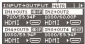
- You can determine the current output mode by checking the output mode icon on the top screen.
Output mode icon
text_image
INPUT→OUTPUT MATR IN1→OUT1 HDCP IN2→OUT2 720/59.94P 1080/60.00P HDMI HDMI IN4→OUT3 HDCP IN8→OUT4 HDCP 1080/59.94P 1080/59.94P HDMI HDMIApplying a Fade to Output Video
This applies a fade to output video.
- Use the [MENU] button → "TRANSITION" → "TIME" to set the fade time (0.0 to 10.0 sec).
If you want to change to a monochrome picture instantly, set "0.0 sec" as the value.
* The "TIME" setting is shared with the length of time for which video transitions (p. 19) are applied.
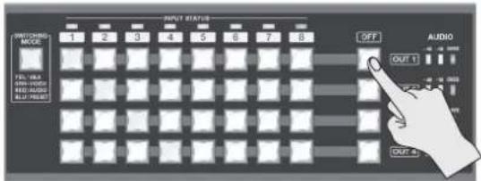
- Press the [OFF] button for the video output channel where you want the fade-out to occur.
text_image
OUTPUT STATUS 1 2 3 4 5 6 7 8 SWITCHING MODE YEL-18A RAN-100G RED-100G BLUE-790GT OFF AUDIO OUT 1 OUT 4XS-84H
The video fades out over the time interval you set in step 1. The [OFF] button flashes while the fade takes place. When the fade-out has been completed, the [OFF] button stops flashing and stays lighted.
- To perform a fade-in, press the [OFF] button a second time.
The [OFF] button flashes and video output starts.
When the fade-in has been completed, the [OFF] button goes dark.
MEMO
- You can change the fade color. Use the [MENU] button → "OFF SWITCH" → "RED," "GREEN," or "BLUE" to adjust the color. The setting for fade color is shared with video transitions (p. 19).
- By default, the system is set up so that audio also fades out or in as a video fade-out or fade-in occurs.
To decouple the audio from this, select the [MENU] button → "OFF SWITCH" → "AUDIO FOLLOW," and set it to "OFF."
Adjusting Microphone Gain
This adjusts the input sensitivity of microphones connected to the R channels of AUDIO INPUT connectors 1 and 2.
MEMO
- Input sensitivity can be adjusted for only the R channel of AUDIO INPUT connectors 1 and 2. For microphones, make the connection to the R channel of AUDIO INPUT connector 1 or 2.
- By default, AUDIO INPUT connectors 1 and 2 are configured for stereo input. When connecting a microphone, select the [MENU] button "AUDIO INPUT" "ANALOG-1" or "ANALOG-2" "MONO INPUT," and set it to "ON"(monaural input).
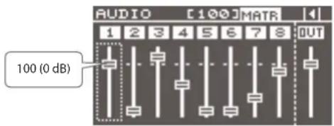
1. Set the volume level of the microphone connected to AUDIO INPUT connector 1 or 2 to "100 (0 dB)."
You can use either of the following two methods to adjust the volume level.
- Change the display to the audio volume control screen, then raise the channel fader to the "100" (0 dB) position.
For more information on how to do this, refer to "Using Audio Faders to Adjust the Volume Level" in the column at right.
text_image
AUDIO [100] MATR 1 2 3 4 5 6 7 8 OUT 100 (0 dB)- Select the [MENU] button → "AUDIO INPUT 1" → "ANALOG-1" or "ANALOG-2" → "INPUT LEVEL," and set this to "100 (0 dB)."
-
Select the [MENU] button → "AUDIO INPUT" → "ANALOG-1" or "ANALOG-2" → "INPUT GAIN."
-
Turn the [VALUE] dial all the way counterclockwise to lower the input sensitivity.
-
Slowly turn the [VALUE] dial clockwise to adjust the input sensitivity.
While inputting actual audio, turn the [VALUE] dial to increase and adjust the input sensitivity.
- Press the [MENU] button to quit the menu.
Adjusting the Volume Balance of Input Audio
This adjusts the volume balance of the audio input to the unit.
NOTE
Even when an HDMI connection is used, no HDMI audio is input unless "HDMI" has been selected in the settings for the video input channel (p. 19).
Using Audio Faders to Adjust the Volume Level
You operate the audio faders shown on the display to adjust the volume levels.
- Before you start, make the settings for the audio input channels assigned to the audio faders on the display (p. 18).
- Use the cursor buttons to switch the display to the screen for audio volume control (p. 18).
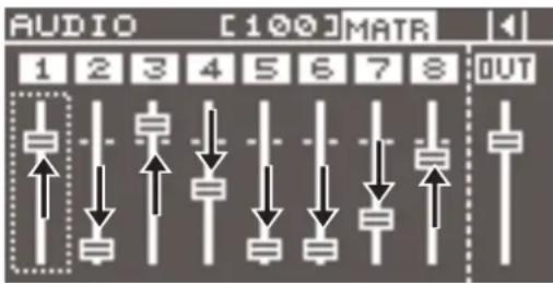
- Raise or lower the audio faders to adjust the volume balance for each channel.
Turn the [VALUE] dial to select the audio fader to operate (1 through 8), then press the [VALUE] dial to apply the selection.
Turn the [VALUE] dial to adjust the volume level of the input channel. Pressing the [VALUE] dial once more lets you select the audio fader to operate.
text_image
AUDIO [100] MATR 1 2 3 4 5 6 7 8 OUTUsing the Menus to Adjust the Volume Level
-
Select the [MENU] button → "AUDIO INPUT" → "HDMI-1" through "HDMI-8" or "ANALOG-1" through "ANALOG-8" → "INPUT LEVEL," then adjust the volume level.
-
Press the [MENU] button to quit the menu.
Adjusting the Volume Level of Output Audio
This adjusts the volume level of output audio.
Checking the Volume Level
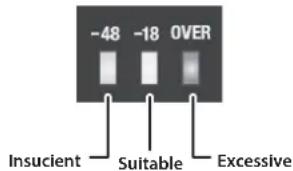
- See the level meter to check the volume level of output audio.
text_image
-48 -18 OVER Insucient Suitable ExcessiveIf "OVER" lights up, the volume level is too high.
A level where the "-18" indicator lights up when peak-volume audio is input is appropriate.
NOTE
If the volume level of speaker output is not appropriate even after adjusting so that “-18” lights up only at peak volume, adjust the volume levels of the speakers and amplifiers. Using the output channel faders to make adjustments might result in distortion or reduced sound quality. Use the audio faders to adjust the volume level.
Using Audio Faders to Adjust the Volume Level
- Before you start, make the settings for the audio output channels assigned to the audio faders on the display (p. 18).
- Use the cursor buttons to switch the display to the screen for audio volume control (p. 18).
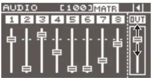
- Raise or lower the audio faders to adjust the volume levels.
Turn the [VALUE] dial to select the output audio fader, then press the [VALUE] dial to apply the selection. Turn the [VALUE] dial to adjust the output-channel volume level.
Pressing the [VALUE] dial once more lets you select the audio fader to operate.
text_image
AUDIO [100] MATR 1 2 3 4 5 6 7 8 OUTUsing the Menus to Adjust the Volume Level
- Select the [MENU] button → "AUDIO OUTPUT" → "OUTPUT-1" to "OUTPUT-4"(Note: This varies according to the model.) → "OUTPUT LEVEL," then adjust the volume level.
- Press the [MENU] button to quit the menu.
Saving/Recalling Settings (Presets)
You can internally save current cross points, audio/video settings, and other values as presets and recall them for use when needed. The unit can save 32 presets.
Saving Settings
- Select the [MENU] button → "PRESET MEMORY" → "SAVE SETTING" → a save-destination preset number (1 to 32), then press the [VALUE] button.
- Check the message and press the [VALUE] dial. (If you want to quit, press the [EXIT] button.) The current settings are saved as a preset.
- Press the [MENU] button to quit the menu.
MEMO
The settings for the categories listed below are not saved in each individual preset. Only a single set is saved in the unit.
•EDID ((DATA1-DATA8)
•RS-232C
•LAN
•WIRELESS LAN
- USB MEMORY
• SYSTEM
After settings for menu items have been made, the new values are saved in the unit's internal memory when you exit the menu.
Saving Settings on a USB Flash Drive
You can save all presets and system settings grouped together into a single file on a USB flash drive inserted into the USB port.
* When you're using a USB flash drive for the first time, be sure to format it on the unit (p. 28).
Saving Settings
To execute this, select the [MENU] button → "USB MEMORY" → "SAVE PRESET" or "SAVE AS PRESET."
Importing Settings
To execute this, select the [MENU] button → "USB MEMORY" → "LOAD PRESET" → the file you want to import.
Recalling Settings
This calls up a saved preset.
When recalling a preset, by pre-specifying the setting values to call up, you can recall just some settings without having to call up all stored settings.
NOTE
If changes are made in the video input connectors or the output format in the preset before and after recalling, output video might become corrupted.
- Specify the setting values in the preset that you want to recall.
Select the [MENU] button → "PRESET MEMORY" → "RECALL SAFE" → "ON," then press the [VALUE] dial.
The "RECALL SAFE" popup appears. Specify whether the settings for the following items are individually recalled (OFF) or not individually recalled (ON).
| Setting items Description | |
| VIDEO INPUT Video input settings, input EDID assignment settings | |
| VIDEO OUTPUT Video output settings | |
| OUT RESOLUTION Output resolution setting | |
| TRANSITION Video transition time/fade time setting | |
| OFF SWITCH [OFF] switch settings | |
| MULTI Multi-view settings | |
| AUDIO INPUT Audio input settings | |
| AUDIO OUTPUT Audio output settings | |
| AUDIO CONTROL | Fader assignment settings at the audio volume control screen |
| MODE Output mode settings | |
| CROSSPOINT Cross-point selection button settings | |
- Press the [SWITCHING MODE] button several times to make it light up in blue (preset mode).
Preset numbers are assigned to the cross-point selection buttons as shown below.
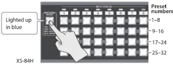
text_image
Lighted up in blue X5-84H Preset numbers 1-8 9-16 17-24 25-32* The cross-point selection buttons for numbers where presets are saved light up in blue.
* XS-82H/XS-83H: If a preset number has no corresponding cross-point selection button, use the [MENU] button → "PRESET MEMORY" → "LOAD SETTINGS" to specify the preset number and recall the settings.
- Press the cross-point selection button for the preset number whose setting you want to recall.
The settings are recalled. The currently selected cross-point selection button lights up in light blue.
MEMO
You can also recall a specified preset at startup. Use the [MENU] button → "SYSTEM" → "STARTUP" to specify the preset number you want to recall.
Formatting USB Flash Drives
When you're using a USB flash drive for the first time, it must first be formatted on the unit.
NOTE
- USB flash drives not formatted on the unit cannot be recognized.
- Performing formatting causes all data already saved on the USB flash drive to be deleted. If the flash drive contains necessary data, back it up onto a computer or elsewhere before formatting the drive.
Making the Connection
Carefully insert the USB flash drives all the way in—until it is firmly in place.
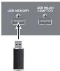
text_image
USB MEMORY USB WLAN ADAPTORNOTE
- Never turn off the power or disconnect the USB flash drives while the screen indicates "Please wait...."
- After connecting the USB flash drive, a short wait may be required until reading and writing data become possible.
Performing Formatting
-
Select the MENU button → "USB MEMORY" → "FORMAT," then press the [VALUE] dial.
-
Check the message and press the [VALUE] dial. (If you want to quit, press the [EXIT] button.)
Formatting of the USB flash drive is carried out.
- Press the [MENU] button to quit the menu.
Returning Settings to the Factory-default State (Factory Reset)
This returns the values of the unit's setting to their factory defaults. If operation that differs from what is described in the owner's manual occurs even when the steps described are followed correctly, try performing a factory reset.
NOTE
Performing a factory reset causes all settings made, values saved in presets (p. 27), and any imported still image (p. 21) to be lost.
-
Select the [MENU] button → "SYSTEM" → "FACTORY RESET," then press the [VALUE] dial.
-
Check the message and press the [VALUE] button. (If you want to quit, press the [EXIT] button.)
A factory reset is executed.
- Press the [MENU] button to quit the menu.
Remote Control from an External Device
The XS-80H Remote application for the iPad is compatible with version 1.1 and later of the system program for this unit.
You can check the version of the system program by selecting the [MENU] button → "SYSTEM" → "VERSION."
Inserting a wireless USB adapter (sold separately) into the USB WIRELESS ADAPTOR connector lets you operate the unit remotely by using the XS-80H Remote application for the iPad.
* For the wireless USB adaptor, use the ONKYO UWF-1 or Roland WNA1100-RL.
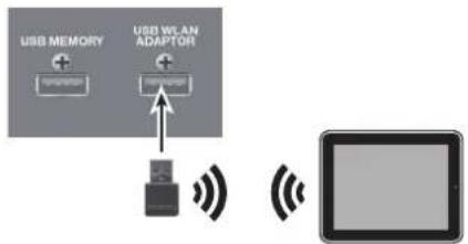
flowchart
graph TD
    A["USB MEMORY"] --> B["Adaptor"]
    C["USB WLAN ADAPTOR"] --> D["Adaptor"]
    D --> E["Device"]
    style A fill:#f9f,stroke:#333
    style C fill:#f9f,stroke:#333
    style D fill:#ccf,stroke:#333
    style E fill:#cff,stroke:#333
You can use the RS-232C connector or LAN port to operate the unit remotely from a computer or other external device.
You can also use the XS-80H Remote application to operate the unit remotely via a Wi-Fi router connected to the LAN port.
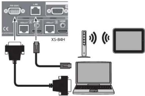
text_image
RS-2300 LAR HS6667 HS6667 HGMI XS-84H USB USB USB USB USB USB USB USB USB USB USB USB USB USB USB USB USB USB USB USB USB USBFor detailed information about remote control, download and refer to the Reference Manual (PDF) from the following Roland website.
https://proav.roland.com/manuals/
Troubleshooting
| Problem Items to check Action Page | |||
| Problems with Video | |||
| No picture is input. | Is the type of incoming video signal set correctly for each video input channel? | Set the video-signal type for each individual video input channel.Video might not be displayed, or might be displayed improperly, if the type of video signal is not set correctly. | p. 19 |
| Is copyright-protected (HDCP) video being input? | When inputting copyright-protected (HDCP) video signals, set "HDCP INPUT ENABLE" to "ENABLE." | p. 20 | |
| No picture is output. | Is the output resolution set correctly? | Set the output resolution for each individual output channel.Use "VIDEO OUTPUT" → "OUTPUT-1" through "OUTPUT-4" → "RESOLUTION" to change the setting. | — |
| Is copyright-protected (HDCP) video being output? | When outputting copyright-protected (HDCP) video signals, set "HDCP OUTPUT ENABLE" to "ENABLE." | p. 20 | |
| Check whether an HDCP-compatible monitor is being used. | — | ||
| When all of the following conditions obtain, the multi-view output channel is a black picture.The video output mode is at a setting from "MULTI-2" to "MULTI-4.""HDCP OUTPUT ENABLE" for the output channel is set to "DISABLE.""Copyright-protected (HDCP) video is being input in one of the multi-view windows. | — | ||
| Is the correct OUTPUT connector (HDMI or HDBaseT output connector) selected? | Simultaneously outputting video from both the HDMI output connector and the HDBaseT output connector on the same channel is not possible.By factory default, the selection of HDMI output and HDBaseT output is set at "AUTO" (the setting for automatic detection on connection). When devices are connected to both the HDMI OUTPUT connector and the HDBaseT OUTPUT connector, HDMI output takes precedence.When you want to output video from a specified OUTPUT connector, change the "OUTPUT SELECT" setting. | p. 21 | |
| Colors are incorrect. | Does the color space of the video being input or output match the color space for the processing being done by the unit? | Change the "COLOR SPACE" settings for "VIDEO INPUT" and "VIDEO OUTPUT." | — |
| Depending on the device, the color space might be interlinked with the selection of DVI or HDMI or the selected format. In such happens, changing the color space on the input or output device might bring about improvement for the problem. | |||
| HDMI output shown on a display has its periphery cut off. | Are the display settings compatible? | In the case of HDMI signals, automatic overscan occurs on some displays.Change the display's settings. | — |
| Problems with Audio | |||
| No audio Is output.The audio volume is too low. | Is the volume turned down on the connected amplifiers or speakers? | Adjust to an appropriate volume level. | — |
| Is the volume turned down on the unit? Adjust the volume | Name of input and output audio to appropriate levels. | p. 25p. 26 | |
| Are copyright-protected (HDCP) signals being sent in a mixed state to a video output connector for which "HDCP OUTPUT ENABLE" is set to "DISABLE"? | When inputting or outputting video on which no copyright protection (HDCP) is applied, the effects of HDCP on other channels might result in no audio output.For details, refer to "Important Notes When Working with Copyright-protected (HDCP) Video" in the Reference Manual (PDF). https://proav.roland.com/manuals/ https://proav.roland.com/manuals/ | — | |
| Is gain (input sensitivity) turned down on audio channels 1 and 2? | When the input sensitivity is turned down on audio channels 1 and 2, no audio is output even when the volume is raised. Go to "AUDIO INPUT" and use "INPUT GAIN" to adjust the input sensitivity. | p. 25 | |
| Is a condenser microphone connected? | When connecting a condenser microphone or other device that requires phantom power, go to "AUDIO INPUT" and set "PHANTOM POWER" to "ON." | p. 15 | |
| Other Problems | |||
| A USB flash drive cannot be read. | Was the USB flash drive formatted on the unit? | When you're using a USB flash drive for the first time, be sure to format it on the unit. | p. 28 |
| Was a non-Roland USB flash drive used? | Operation of non-Roland USB flash drives cannot be assured.Operation has been tested for commonly available USB flash drives, but operation with all USB flash drives is not assured. Depending on the manufacturer and type of the USB flash drive, correct operation may not be possible. | — | |
| The unit Is extremely hot. | Has the cooling fan stopped? | Immediately stop use and contact a Roland Service Center. | — |
Block Diagram
Video Block
HDMI/DVI Inputs x 8
Analog Video Inputs x 8
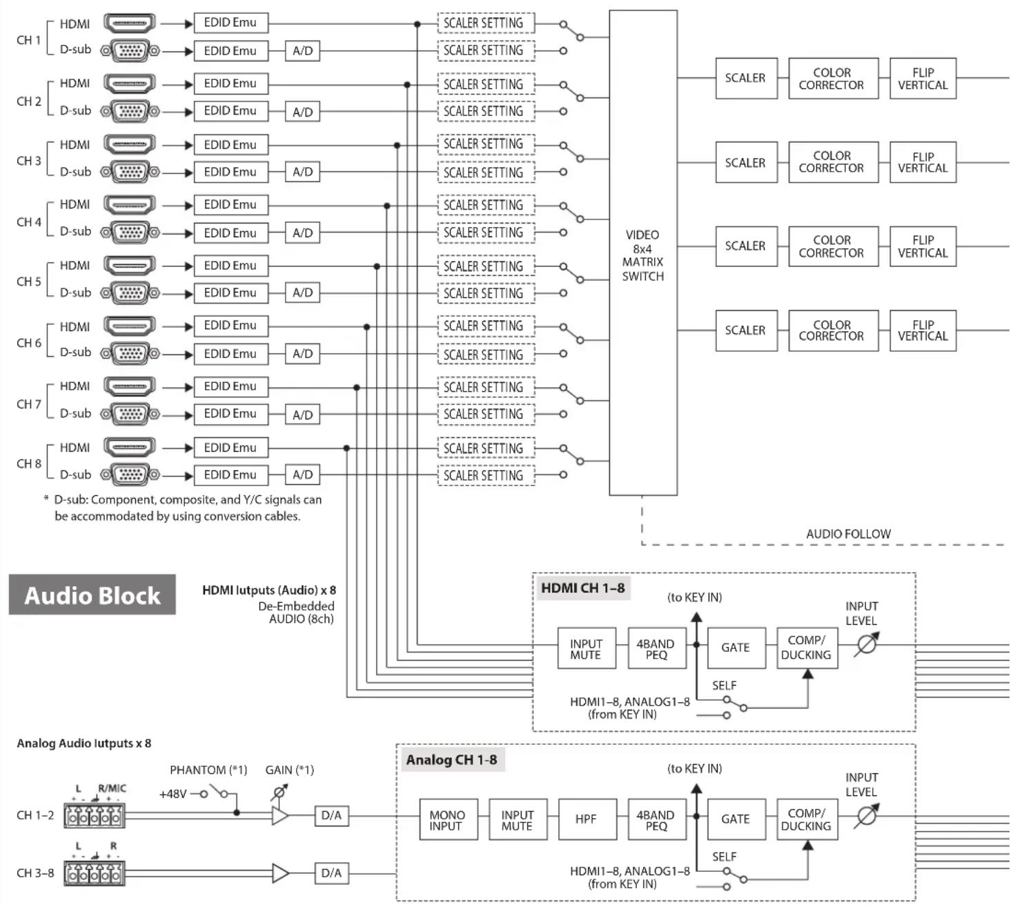
flowchart
graph TD
    subgraph Audio Block
        CH1["HDMI"] --> EDID1["EDID Emu"] --> A0["A/D"] --> SCALER1["SCALER SETTING"] --> VIDEO["VIDEO 8x4 MATRIX SWITCH"]
        CH2["HDMI"] --> EDID2["EDID Emu"] --> A1["A/D"] --> SCALER2["SCALER SETTING"] --> VIDEO
        CH3["HDMI"] --> EDID3["EDID Emu"] --> A2["A/D"] --> SCALER3["SCALER SETTING"] --> VIDEO
        CH4["HDMI"] --> EDID4["EDID Emu"] --> A3["A/D"] --> SCALER4["SCALER SETTING"] --> VIDEO
        CH5["HDMI"] --> EDID5["EDID Emu"] --> A4["A/D"] --> SCALER5["SCALER SETTING"] --> VIDEO
        CH6["HDMI"] --> EDID6["EDID Emu"] --> A5["A/D"] --> SCALER6["SCALER SETTING"] --> VIDEO
        CH7["HDMI"] --> EDID7["EDID Emu"] --> A6["A/D"] --> SCALER7["SCALER SETTING"] --> VIDEO
        CH8["HDMI"] --> EDID8["EDID Emu"] --> A7["A/D"] --> SCALER8["SCALER SETTING"] --> VIDEO
        CH1-2["L R/MIC"] --> PHANTOM["*1"] --> D/A["D/A"] --> ANOCH1["ANOG1-8 (from KEY IN)"]
        CH3-8["L R"] --> D/A["D/A"]
    end

    subgraph Analog Audio Inputs x 8
        CH1-2 --> PHANTOM
        PHANTOM --> PHANTOM1["*1"]
        PHANTOM1 --> PHANTOM2["*1"]
        PHANTOM2 --> PHANTOM3["*1"]
        PHANTOM3 --> PHANTOM4["*1"]
        PHANTOM4 --> PHANTOM5["*1"]
        PHANTOM5 --> PHANTOM6["*1"]
        PHANTOM6 --> PHANTOM7["*1"]
        PHANTOM7 --> PHANTOM8["*1"]
        PHANTOM8 --> PHANTOM9["*1"]
        PHANTOM9 --> PHANTOM10["*1"]
        PHANTOM10 --> PHANTOM11["*1"]
        PHANTOM11 --> PHANTOM12["*1"]
        PHANTOM12 --> PHANTOM13["*1"]
        PHANTOM13 --> PHANTOM14["*1"]
        PHANTOM14 --> PHANTOM15["*1"]
        PHANTOM15 --> PHANTOM16["*1"]
        PHANTOM16 --> PHANTOM17["*1"]
        PHANTOM17 --> PHANTOM18["*1"]
        PHANTOM18 --> PHANTOM19["*1"]
        PHANTOM19 --> PHANTOM20["*1"]
        PHANTOM20 --> PHANTOM21["*1"]
        PHANTOM21 --> PHANTOM22["*1"]
        PHANTOM22 --> PHANTOM23["*1"]
        PHANTOM23 --> PHANTOM24["*1"]
        PHANTOM24 --> PHANTOM25["*1"]
        PHANTOM25 --> PHANTOM26["*1"]
        PHANTOM26 --> PHANTOM27["*1"]
        PHANTOM27 --> PHANTOM28["*1"]
        PHANTOM28 --> PHANTOM29["*1"]
        PHANTOM29 --> PHANTOM30["*1"]
        PHANTOM30 --> PHANTOM31["*1"]
        PHANTOM31 --> PHANTOM32["*1"]
        PHANTOM32 --> PHANTOM33["*1"]
        PHANTOM33 --> PHANTOM34["*1"]
        PHANTOM34 --> PHANTOM35["*1"]
        PHANTOM35 --> PHANTOM36["*1"]
        PHANTOM36 --> PHANTOM37["*1"]
        PHANTOM37 --> PHANTOM38["*1"]
        PHANTOM38 --> PHANTOM39["*1"]
        PHANTOM39 --> PHANTOM40["*1"]
        PHANTOM40 --> PHANTOM41["*1"]
        PHANTOM41 --> PHANTOM42["*1"]
        PHANTOM42 --> PHANTOM43["*1"]
        PHANTOM43 --> PHANTOM44["*1"]
        PHANTOM44 --> PHANTOM45["*1"]
        PHANTOM45 --> PHANTOM46["*1"]
        PHANTOM46 --> PHANTOM47["*1"]
        PHANTOM47 --> PHANTOM48["*1"]
        PHANTOM48 --> PHANTOM49["*1"]
        PHANTOM49 --> PHANTOM50["*1"]
        PHANTOM50 --> PHANTOM51["*1"]
        PHANTOM51 --> PHANTOM52["*1"]
        PHANTOM52 --> PHANTOM53["*1"]
        PHANTOM53 --> PHANTOM54["*1"]
        PHANTOM54 --> PHANTOM55["*1"]
        PHANTOM55 --> PHANTOM56["*1"]
        PHANTOM56 --> PHANTOM57["*1"]
        PHANTOM57 --> PHANTOM58["*1"]
        PHANTOM58 --> PHANTOM59["*1"]
        PHANTOM59 --> PHANTOM60["*1"]
        PHANTOM60 --> PHANTOM61["*1"]
        PHANTOM61 --> PHANTOM62["*1"]
        PHANTOM62 --> PHANTOM63["*1"]
        PHANTOM63 --> PHANTOM64["*1"]
        PHANTOM64 --> PHANTOM65["*1"]
        PHANTOM65 --> PHANTOM66["*1"]
        PHANTOM66 --> PHANTOM67["*1"]
        PHANTOM67 --> PHANTOM68["*1"]
        PHANTOM68 --> PHANTOM69["*1"]
        PHANTOM69 --> PHANTOM70["*1"]
        PHANTOM70 --> PHANTOM71["*1"]
        PHANTOM71 --> PHANTOM72["*1"]
        PHANTOM72 --> PHANTOM73["*1"]
        PHANTOM73 --> PHANTOM74["*1"]
        PHANTOM74 --> PHANTOM75["*1"]
        PHANTOM75 --> PHANTONE
    end

    subgraph Analog Audio Inputs x 8
    CH1-2
    CH3-8
    end

    subgraph Analog Audio Outputs x 8
    CH1-2
    CH3-8
    end

    note right of CHI
    note left of CHI
    note right of ANOCH
    note bottom of CHI
    note top of ANOCH
    note bottom of ANOCH
    note top of ANOCH
    note bottom of ANOCH
    note top of ANOCH
    note bottom of ANOCH
    note top of ANOCH
    note bottom of ANOCH
(*1) Phantom power and gain are enabled only for the R channels of analog input channels 1 and 2.
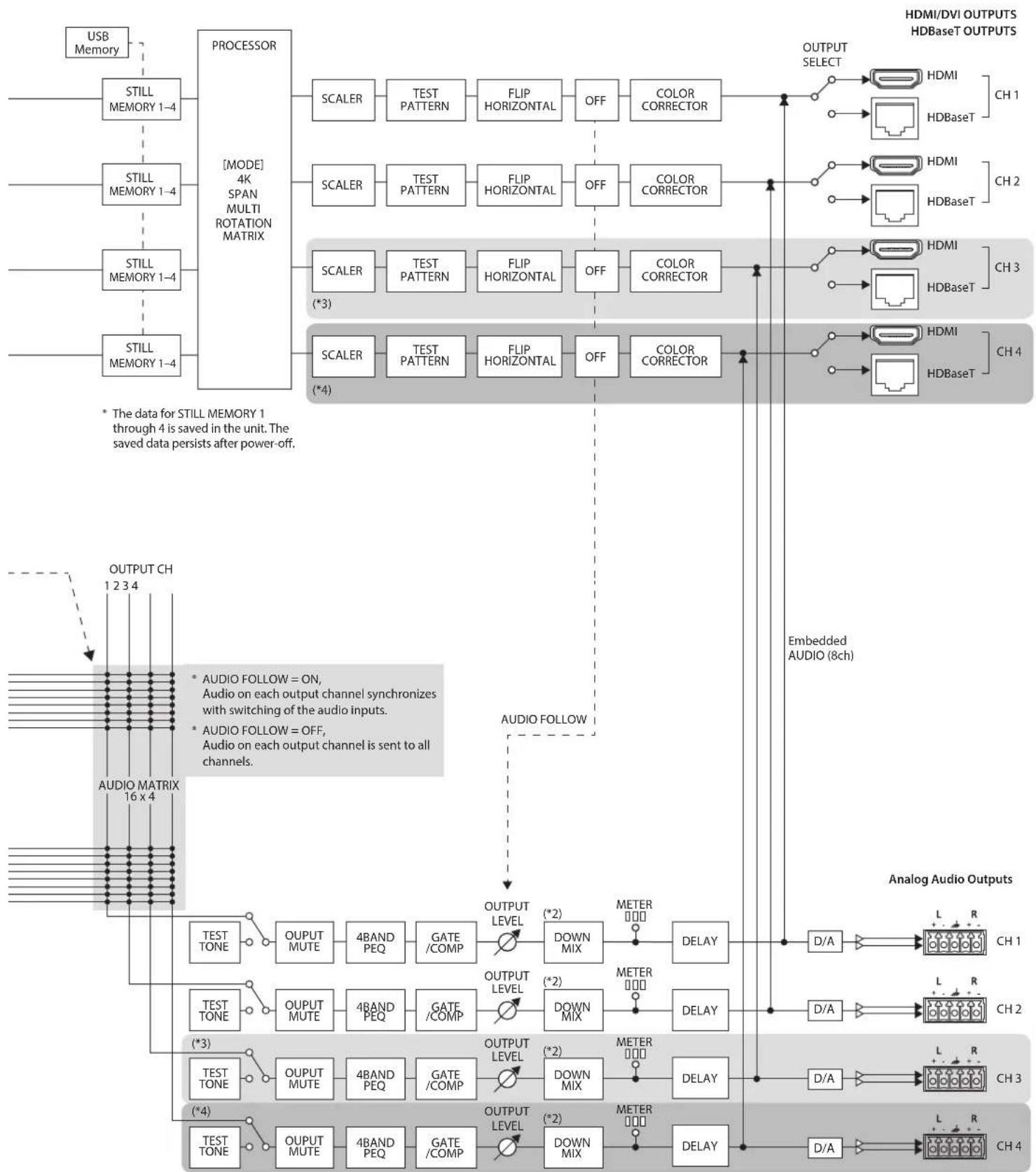
flowchart
graph TD
    A["USB Memory"] --> B["STILL MEMORY 1-4"]
    B --> C["PROCESSOR [MODE"] 4K SPAN MULTI ROTATION MATRIX]
    C --> D1["SCALER"]
    C --> D2["SCALER"]
    C --> D3["SCALER (*3)"]
    C --> D4["SCALER (*4)"]
    D1 --> E1["TEST PATTERN"]
    D2 --> E2["TEST PATTERN"]
    D3 --> E3["TEST PATTERN"]
    D4 --> E4["TEST PATTERN"]
    E1 --> F1["FLIP HORIZONTAL"]
    E2 --> F2["FLIP HORIZONTAL"]
    E3 --> F3["FLIP HORIZONTAL"]
    E4 --> F4["FLIP HORIZONTAL"]
    F1 --> G1["OFF"]
    F2 --> G2["OFF"]
    F3 --> G3["OFF"]
    F4 --> G4["OFF"]
    G1 --> H1["COLOR CORRECTOR"]
    G2 --> H2["COLOR CORRECTOR"]
    G3 --> H3["COLOR CORRECTOR"]
    H1 --> I1["OUTPUT SELECT"]
    H2 --> I2["HDMI"]
    H3 --> I3["HDMI"]
    H4 --> I4["HDMI"]
    I1 --> J1["HDBaseT CH1"]
    I2 --> J2["HDBaseT CH2"]
    I3 --> J3["HDBaseT CH3"]
    I4 --> J4["HDBaseT CH4"]
    J1 --> K["Embedded AUDIO (8ch)"]
    J2 --> K
    J3 --> K
    J4 --> K
    K --> L["Analog Audio Outputs"]
    L --> M["D/A"]
    M --> N["L R CH1"]
    L --> O["D/A"]
    O --> P["L R CH2"]
    L --> Q["D/A"]
    Q --> R["L R CH3"]
    L --> S["D/A"]
    S --> T["L R CH4"]
    style A fill:#f9f,stroke:#333
    style B fill:#ccf,stroke:#333
    style C fill:#cfc,stroke:#333
    style D1 fill:#fcc,stroke:#333
    style D2 fill:#fcc,stroke:#333
    style D3 fill:#fcc,stroke:#333
    style D4 fill:#fcc,stroke:#333
    style E1 fill:#cff,stroke:#333
    style E2 fill:#cff,stroke:#333
    style E3 fill:#cff,stroke:#333
    style E4 fill:#cff,stroke:#333
    style E5 fill:#ffc,stroke:#333
    style E6 fill:#ffc,stroke:#333
    style E7 fill:#ffc,stroke:#333
    style E8 fill:#ffc,stroke:#333
    style E9 fill:#ffc,stroke:#333
    style F1 fill:#ffc,stroke:#333
    style F2 fill:#ffc,stroke:#333
    style F3 fill:#ffc,stroke:#333
    style F4 fill:#ffc,stroke:#333
    style F5 fill:#ffc,stroke:#333
    style F6 fill:#ffc,stroke:#333
    style F7 fill:#ffc,stroke:#333
    style F8 fill:#ffc,stroke:#333
    style F9 fill:#ffc,stroke:#333
(*2) DOWN MIX: From the menu, set "OFF," "STEREO > MONO," "5.1ch > STEREO," "5.1ch > MONO."
(*3): XS-83H and XS-84H only
(*4): XS-84H only
Connector Specifications
Analog video INPUT connectors
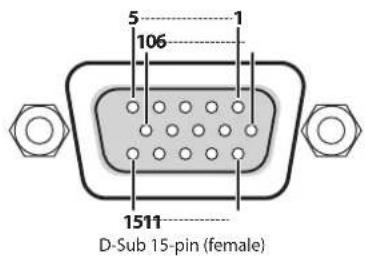
text_image
5 106 1 1511 D-Sub 15-pin (female)| Pin No. | Input video signal type | |||
| RGB Component Composite YC | ||||
| 1 Red Pr/Cr | ||||
| 2 Green/G on Sync Y VIDEO Y | ||||
| 3 Blue Pb/Cb C | ||||
| 4 | ||||
| 5 GND | ||||
| 6 GND | GND | |||
| 7 GND | GND | GND | GND | |
| 8 GND | GND | GND | ||
| 9 DDC +5V | ||||
| 10 | GND | |||
| 11 | ||||
| 12 DDC data | ||||
| 13 HD | ||||
| 14 | VD | |||
| 15 | DDC clock | |||
RS-232C connector
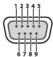
D-Sub 9-pin (male)
| Pin No. | Signal |
| 1 | |
| 2 | RXD |
| 3 | TXD |
| 4 | DTR |
| 5 | GND |
| 6 | DSR |
| 7 | RTS |
| 8 | CTS |
| 9 |
| Communication method | Synchronous (asynchronous), full-duplex |
| Communication speed | 9600 bps/38400 bps |
| Parity | none |
| Data length 8 bit | |
| Stop bit | 1 bit |
| Code set | ASCII |
| Flow Control | XON/XOFF |
Cable Wiring Diagram
Wire the three lines of RXD, TXD, and GND as shown in the figure below.
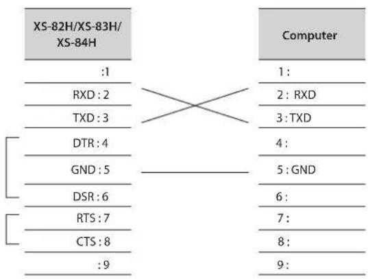
flowchart
graph TD
    A["XS-82H/XS-83H/XS-84H"] --> B[":1"]
    A --> C["RXD: 2"]
    A --> D["TXD: 3"]
    A --> E["DTR: 4"]
    A --> F["GND: 5"]
    A --> G["DSR: 6"]
    A --> H["RTS: 7"]
    A --> I["CTS: 8"]
    A --> J[":9"]
    K["Computer"] --> L["1:"]
    K --> M["2: RXD"]
    K --> N["3: TXD"]
    K --> O["4:"]
    K --> P["5: GND"]
    K --> Q["6:"]
    K --> R["7:"]
    K --> S["8:"]
    K --> T["9:"]
* The connections between 4 and 6 and between 7 and 8 are inside the unit.
* When connecting to a controlling device (such as an RS-232C-compatible computer), use a crossover cable.
AUDIO INPUT/OUTPUT connectors
The AUDIO INPUT and OUTPUT connectors are wired as shown in the figure below.
Wire the cables correctly, according to whether you're using balanced or unbalanced connections.
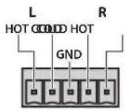
TRS plug
Balanced connection
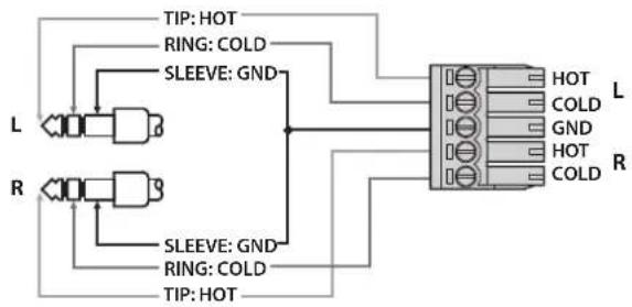
flowchart
graph TD
    L["Left Terminal L"] -->|TIP: HOT| H1["Hot"]
    R["Right Terminal R"] -->|SLEEVE: GND| H2["Hot"]
    L -->|RING: COLD| H3["Hot"]
    R -->|SLEEVE: GND| H4["Hot"]
    H1 --> H5["COLD"]
    H2 --> H6["COLD"]
    H3 --> H7["L"]
    H4 --> H8["R"]
    H5 --> H9["L"]
    H6 --> H10["R"]
Unbalanced connection
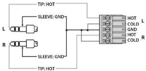
flowchart
graph TD
    A["L"] --> B["SLEEVE: GND"]
    C["R"] --> D["SLEEVE: GND"]
    B --> E["Hot"]
    D --> F["Hot"]
    E --> G["COLD"]
    F --> H["COLD"]
    style A fill:#f9f,stroke:#333
    style C fill:#f9f,stroke:#333
    style E fill:#ccf,stroke:#333
    style G fill:#cfc,stroke:#333
    style H fill:#cfc,stroke:#333
    style_I["TIP: HOT"] --> J["L"]
    I --> K["R"]
XLR plug (female)
Balanced connection
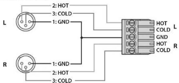
text_image
L 2: HOT 3: COLD 1: GND R 1: GND 2: HOT 3: COLD HOT L COLD GND HOT R COLDUnbalanced connection
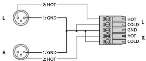
text_image
L 2: HOT 1: GND R 1: GND 2: HOT HOT COLD GND HOT COLD L RRCA pin plug
Unbalanced connection
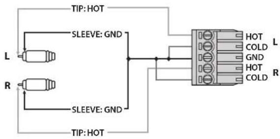
text_image
TIP: HOT L SLEEVE: GND R SLEEVE: GND TIP: HOT HOT COLD L GND HOT COLD RMicrophones
Balanced connection
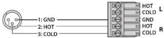
text_image
1: GND 2: HOT 3: COLD HOT COLD GND HOT COLD L RUnbalanced connection
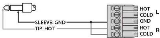
text_image
SLEEVE: GND TIP: HOT HOT COLD GND HOT COLD L RMain Specifications
Video
| Video processing 4:4:4 (Y/Pb/Pr), 10-bit | ||||
| Input Connectors | HDMI Type A (19) | pins) x 8 (INPUT 1-8) * HDCP Supported | ||
| RGB/ Component/ Composite/S- Video | HD DB-15 type x 8 (INPUT 1-8) | |||
| Output Connectors | XS-82H | HDMI Type A (19) | pins) x 2 (OUTPUT1-2) | * HDCP Supported |
| HDBaseT RJ-45 x | 2(OUTPUT1-2) | |||
| XS-83H | HDMI Type A (19) | pins) x 3 (OUTPUT1-3) | * HDCP Supported | |
| HDBaseT RJ-45 x | 3(OUTPUT1-3) | |||
| XS-84H | HDMI Type A (19) | pins) x 4 (OUTPUT1-4) | * HDCP Supported | |
| HDBaseT RJ-45 x | 4 (OUTPUT1-4) | |||
| Input Level and Impedance | Analog RGB 0.7 | Vp-p 75 ohms (H, V: 5 VTTL) | ||
| Analog HD 1.0 Vp-p 75 ohms (Sync-Signal: Bi-Level/Tri-Level) | ||||
| Composite/ S-Video | Signal Level 1.0 Vp-p (luminance), 0.286 Vp-p (chroma(NTSC)), 0.3 Vp-p (chroma(PAL)) | |||
| Impedance 75 ohms | ||||
| Scan Converter | INPUT | Aspect ratio control, Image adjustment function (Brightness, Contrast, Color adjustment, Display position, Size, Flip vertical)* Settings can be saved in memory for each input. | ||
| OUTPUT | Image adjustment function(Brightness, Contrast, Color adjustment, Display position, Size, Flip horizontal, Crop)* Settings can be saved in memory for each output. | |||
| Input formats | HDMI | 480/59.94i, 576/50i, 480/59.94p, 576/50p, 720/59.94p, 720/50p, 1080/59.94i, 1080/50i, 1080/59.94p, 1080/50p, 640 x 480/60 Hz, 800 x 600/60 Hz, 1024 x 768/60 Hz, 1280 x 768/60 Hz, 1280 x 1024/60 Hz, 1366 x 768/60 Hz, 1400 x 1050/60 Hz, 1600 x 1200/60 Hz, 1920 x 1080/60 Hz, 1920 x 1200/60 Hz* The video signal frame rate must match with the unit's frame rate setting.* Conforms to VESA DMT Version 1.0 Revision 11.* 1920 x 1200/60Hz : Reduced blanking | ||
| RGB/ Component | 480/59.94i, 576/50i, 480/59.94p, 576/50p, 720/59.94p, 720/50p, 1080/59.94i, 1080/50i, 1080/59.94p,1080/50p, 640 x 480/60 Hz, 800 x 600/60 Hz, 1024 x 768/60 Hz, 1280 x 768/60 Hz, 1280 x 1024/60 Hz, 1366 x 768/60 Hz, 640 x 480/60 Hz, 800 x 600/60 Hz, 1024 x 768/60 Hz, 1280 x 768/60 Hz, 1280 x 1024/60 Hz, 1366 x 768/60 Hz, 1400 x 1060/60 Hz, 1600 x 1200/60 Hz, 1920 x 1080/60 Hz, 1920 x 1200/60 Hz* The video signal frame rate must match with the unit's frame rate setting.* Conforms to VESA DMT Version 1.0 Revision 11.* 1920 x 1200/6OHz : Reduced blanking | |||
| Composite 480i/ | 59.94, 576i/50 | |||
| S-Video 480i/59. | 94, 576i/50 | |||
| Still Image | Windows Bitmap File (.bmp)* Maximum 1920 x 1200 pixels, 24-bit per pixel, uncompressed. It can be stored up to 4 files in the internal memory. | |||
| Output formats | HDMI/ HDBaseT | 480/59.94i, 576/50i, 480/59.94p, 576/50p, 720/59.94p, 720/50p, 1080/59.94i, 1080/50i, 1080/59.94p, 1080/50p , 640 x 480/60 Hz, 800 x 600/60 Hz, 1024 x 768/60 Hz, 1280 x 768/60 Hz, 1280 x 1024/60 Hz, 1366 x 768/60 Hz, 1600 x 1200/60 Hz, 1920 x 1200/60 Hz* The output refresh rates of 640 x 480-1366 x 768 are 75 Hz when the unit's frame rate setting is 50 Hz.* Conforms to VESA DMT Version 1.0 Revision 11.* 1920 x 1200/6OHz : Reduced blanking | ||
| Video effects | Transition | Seamless switching (Seamless fade through black transition effects are available to enhance presentations by eliminating distractions during switching.) | ||
| Mode Matrix, Multi (Up to 4 Windows),Span, Left and right 90 degrees rotation, 4K | ||||
| Others Flip vertical, Flip horizontal, Output fade, Test pattern output (Colorbar, Hatch,etc) | ||||
| Audio processing Sampling rate 24 bits/48 kHz, 8ch | |||
| Input Connectors | Digital HDMI Type A (19 pins) x 8 | ||
| Analog 5-pin euroblock type x 8 | |||
| Output Connectors | XS-82H | Digital HDMI Type A (19 pins) x 2 | |
| Analog 5-pin euroblock type x 2 | |||
| XS-83H | Digital HDMI Type A (19 pins) x 3 | ||
| Analog 5-pin euroblock type x 3 | |||
| XS-84H | Digital HDMI Type A (19 pins) x 4 | ||
| Analog 5-pin euroblock type x 4 | |||
| Input Level and Impedance | Ch1–2 | Signal Level -60 to +4 dBu (Maximum: +22 dBu) | |
| Impedance Gain 0 to 23 = 10 k ohms, Gain 2 to 60 = 5 k ohms | |||
| Ch3–8 | Signal Level +4 dBu (Maximum: +22 dBu) | ||
| Impedance 8.5 k ohms | |||
| Output Level and Impedance | Ch1–4 | Signal Level +4 dBu (Maximum: +22 dBu) | |
| Impedance 600 ohms | |||
| Audio Formats HDMI Linear PC CM, 24 bit, 48 kHz, 8 ch | |||
| Audio Effects | 16 stereo inputs and 4 outputs digital audio mixer | ||
| Input High-pass filter, Mono, 4-band parametric equalizer, Compressor/Ducking, Gate | |||
| Output 4-band parametric equalizer, Compressor/Gate, Down mix, Lip-sync Delay (1 msec units, max 170 msec) | |||
| Other Test tone output, Synchronized/unsynchronized audio and video function | |||
Other function
Preset memory (32), Key lock function.
Other jacks
| RS-232C 9 pins D-sub type x 1 | |
| LAN RJ-45 x 1 | |
| USB A type x 2 (for USB memories, for WNA1100-RL/ONKYO UWF-1) | |
Display
Graphic LCD 128 x 64 dots
Others
| Power Consumption | XS-82H 55 W | |
| XS-83H 60 W | ||
| XS-84H 70 W | ||
| Dimensions | 481(W) x 353(D) x 88(H) mm18-15/16 (W) x 13-15/16 (D) x 3-1/2 (H) inches * EIA-2U rack mountable | |
| Weight | 6.0 kg13 lbs 4 oz | |
| Operation Temperature | +0 to +40 degrees Celsius+32 to +104 degrees Fahrenheit | |
| Accessories | Power Cord, Euroblock Plug x 12, Rubber Foot x 5, Owner's Manual | |
* 0 dBu=0.775 Vrms
* In the interest of product improvement, the specifications and/or appearance of this unit are subject to change without prior notice.
* This product is intended for use in the following Electromagnetic environments:
E1: residential, E2: commercial and light industrial, E3: urban outdoors, E4: controlled EMC environment, ex. recording studio (broadcasting studio) which are specified in EN55103-1 and EN55103-2.
Dimensions
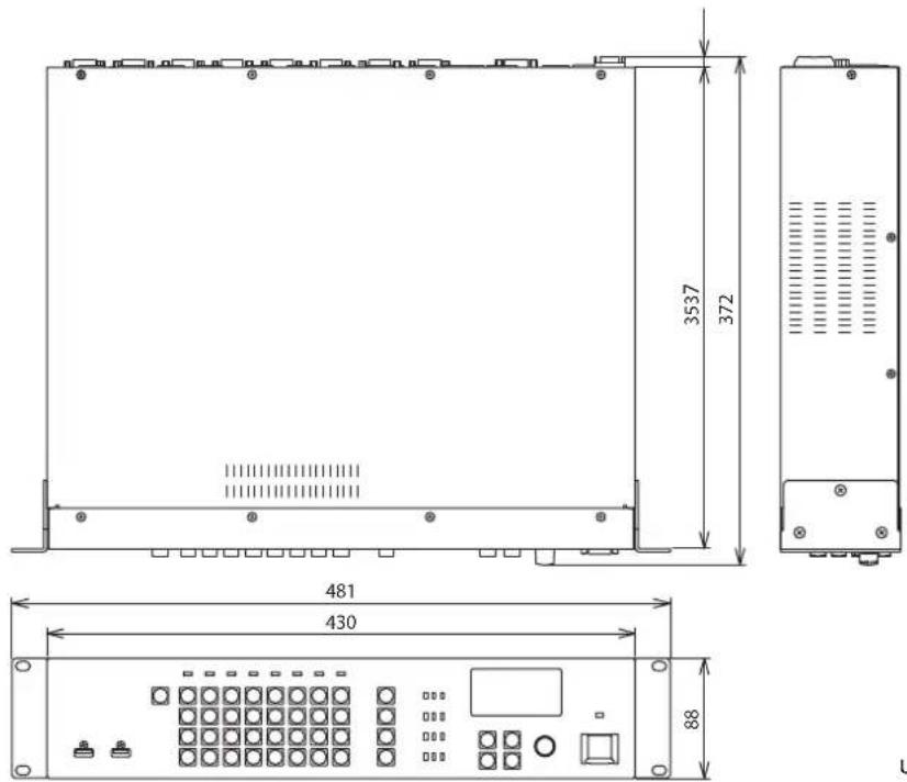
Unit: mm
FEDERAL COMMUNICATIONS COMMISSION RADIO FREQUENCY INTERFERENCE STATEMENT
This equipment has been tested and found to comply with the limits for a Class B digital device, pursuant to Part 15 of the FCC Rules. These limits are designed to provide reasonable protection against harmful interference in a residential installation. This equipment generates, uses, and can radiate radio frequency energy and, if not installed and used in accordance with the instructions, may cause harmful interference to radio communications. However, there is no guarantee that interference will not occur in a particular installation. If this equipment does cause harmful interference to radio or television reception, which can be determined by turning the equipment off and on, the user is encouraged to try to correct the interference by one or more of the following measures:
– Reorient or relocate the receiving antenna.
– Increase the separation between the equipment and receiver.
- Connect the equipment into an outlet on a circuit different from that to which the receiver is connected.
- Consult the dealer or an experienced radio/TV technician for help.
This device complies with Part 15 of the FCC Rules. Operation is subject to the following two conditions:
(1) this device may not cause harmful interference, and
(2) this device must accept any interference received, including interference that may cause undesired operation.
This equipment requires shielded interface cables in order to meet FCC class B limit.
Any unauthorized changes or modifications not expressly approved by the party responsible for compliance could void the user's authority to operate the equipment.
For Canada
CAN ICES-3 (B)/NMB-3 (B)
For EU Countries
Manufacturer: Roland Corporation
2036-1 Nakagawa, Hosoe-cho, Kita-ku, Hamamatsu, Shizuoka 431-1304, JAPAN
Importer: Roland Corporation
ENA 23 Zone 1 nr. 1620 Klaus-Michael Kuehnelaan 13, 2440 Geel, BELGIUM

For the U.K.
Manufacturer: Roland Corporation
2036-1 Nakagawa, Hosoe-cho, Kita-ku, Hamamatsu, Shizuoka 431-1304, JAPAN
Importer: Roland Europe Group Limited
Hive 2, 1530 Arlington Business Park, Theale, Reading, Berkshire. RG7 4SA United Kingdom

For the USA
DECLARATION OF CONFORMITY Compliance Information Statement
Model Name: XS-82H/XS-83H/XS-84H
Type of Equipment: Video Switcher
Responsible Party: Roland Corporation U.S.
Address: 5100 S. Eastern Avenue Los Angeles, CA 90040-2938
Telephone: (323) 890-3700
For EU Countries

This product is intended for use in the following Electromagnetic environments:
E1: residential, E2: commercial and light industrial, E3: urban outdoors, E4: controlled EMC environment,
ex. recording studio (broadcasting studio) which are specified in EN55103-1 and EN55103-2.
For EU Countries

This symbol indicates that in EU countries, this product must be collected separately from household waste, as defined in each region. Products bearing this symbol must not be discarded together with household waste.