
SRX ORCHESTRA - Sound synthesizer ROLAND - Free user manual and instructions
Find the device manual for free SRX ORCHESTRA ROLAND in PDF.


| Product Type | Expansion Sound Board (SRX Series) |
| Wave Memory | 128 MB (16-bit linear, 44.1 kHz) |
| Preset Patches | 512 (256 GM2 + 256 Orchestral) |
| Polyphony | 64 voices |
| Effects | Multi-FX, Reverb, Chorus (per patch) |
| Compatibility | Keyboards with SRX expansion slot (Fantom, Juno, RD series) |
| Dimensions | 110 x 64 x 10 mm |
| Weight | 50 g |
| Power Consumption | 3.0 W (from host) |
| Audio Output | Via host keyboard (analog or digital) |
| Sound Categories | Strings, Woodwinds, Brass, Percussion, Ensemble |
| Installation | Plug into expansion slot; no tools required |
| Repair | No user-serviceable parts; contact Roland service |
| Cleaning | Use dry cloth; avoid liquids |
| Operating Temperature | 0°C to 50°C |
Frequently Asked Questions - SRX ORCHESTRA ROLAND
User questions about SRX ORCHESTRA ROLAND
0 question about this device. Answer the ones you know or ask your own.
Ask a new question about this device
Download the instructions for your Sound synthesizer in PDF format for free! Find your manual SRX ORCHESTRA - ROLAND and take your electronic device back in hand. On this page are published all the documents necessary for the use of your device. SRX ORCHESTRA by ROLAND.
USER MANUAL SRX ORCHESTRA ROLAND
SRX ORCHESTRA Software Synthesizer Owner's Manual

For details on the settings for the DAW software that you're using, refer to the DAW's help or manuals.
About Trademarks
• VST is a registered trademark of Steinberg Media Technologies GmbH.
• The Audio Units logo is a trademark of Apple Inc.
- Roland is a registered trademark or trademark of Roland Corporation in the United States and/or other countries.
- Company names and product names appearing in this document are registered trademarks or trademarks of their respective owners.
Introduction 2
Screen Structure 4
Using SRX ORCHESTRA.... 5
How to Edit Values 5
Initializing a value.... 5
About the KEYBOARD button.... 5
Overview of the SRX ORCHESTRA 6
How the SRX ORCHESTRA is Organized 6
How a Patch is Structured 6
How a Rhythm Set is Structured 6
Calculating the Number of Voices Being Used 6
About the Effects 7
Memory and Bank 8
What is a Memory? 8
Bank 8
Changing to Other Bank.... 8
Exporting the Bank 8
Importing a Bank 8
Creating/Deleting a Bank 8
Renaming a Bank....8
Category.... 9
Memory 9
Loading a Memory.... 9
Saving the Memory 9
Renaming the Memory.... 9
Changing the Order of the Memories 9
Settings 10
Option 10
Detailed Editing for a Patch (PATCH Parameters).... 11
How to Edit a Patch 11
Copying/Pasting Patch Parameters 11
TONE SWITCH/SELECT.... 11
Stereo Wave Settings (Set Stereo Function) 12
PATCH Parameters 13
COMMON 13
STRUCTURE.... 15
WG + PITCH.... 17
TVF 19
TVA.... 21
LFO 23
VELOCITY & KEY RANGE 25
MATRIX CONTROL 26
CONTROL SW 26
Detailed Editing for a Rhythm Set (RHYTHM Parameters) .. 28
How to Edit a Rhythm Set 28
Copying/Pasting Rhythm Parameters 28
WG 28
Stereo Wave Settings (Set Stereo Function) 28
RHYTHM Parameters 29
COMMON 29
WG 29
PITCH + TVF 30
TVA + VELOCITY 32
EFFECTS Parameters 34
Applying Effects 34
Effect Settings.... 34
Signal Flow and Parameters (ROUTING).... 34
Multi-Effect Settings (MFX) 35
Chorus and Reverb Settings.... 36
Effects List 37
Multi-Effects Parameters (MFX) 37
About RATE and DELAY TIME 38
When Using 3D Effects 38
About the STEP RESET function 38
Chorus Parameters.... 69
Reverb Parameters 69
![Main window Here you can select sounds, turn effects on/off, and access windows. [MASTER LEVEL] knob Adjusts the overall volume. [▲] [▼] buttons Select the next or previous memory. [EDIT] button Accesses the edit screen. [NAME] button Renames a memory. Patch Memory name This area shows the name of the selected memory. [UTILITY] button Allows you to copy or paste groups of parameters (such as tone or MFX). [KEYBOARD] button Shows/hides the keyboard window. [OPTION] button Allows you to make various settings and authorizations. [HELP] button Displays help. [MESSAGE] indicator Lights when performance data is received. [ABOUT] button Here you can view information about the SRX ORCHESTRA. Level meter Displays output levels of the SRX ORCHESTRA. LIST Displays a list of sounds. You can select a sound from the list. [BANK] button Displays a list organized by bank. [CATEGORY] button Displays a list organized by category. [TONE SWITCH] [1] [2] [3] [4] buttons Select the tone(s) that will be heard. EFFECTS Press these buttons to turn on/ off the MFX, chorus, or reverb effects. [REVERB] button Turns reverb on/off. [CHORUS] button Turns chorus on/off. [MFX] button Turns multi-effect on/off. Zoom Drag the bottom-right corner of the window to resize (zoom). Zoom = 100%](/content/2026/05/1012690/images/6fa813fceefc9661d1f283b8ddbf611f9c468077df5e0d945151e08a182e940f.jpg)

- In the navigation window, you can click various buttons to choose the parameters that are shown in the parameter window.
- The parameter window shows an editing screen for the parameters that you chose in the navigation window.
- The edit window includes both the parameter window and the navigation window.
How to Edit Values
You can edit values by clicking (and dragging) the buttons, sliders, or knobs.
- If you feel that the sliders and knobs in the panel are too small, and find it difficult to make detailed settings, try clicking (and holding) a knob or slider and then dragging the mouse farther away. This lets you set the value at any position as long as you continue holding down the mouse button. When doing so, you will be able to make precise adjustments to the value whenever the mouse cursor is away from the center of the knob or slider.
- When a value is shown, you can use the cursor keys (up/down/left/right) or mouse wheel to edit the value.
Initializing a value
Windows 7/8.1/10 Users
You can initialize the value of a parameter by holding down the Ctrl key of the computer and clicking the slider or knob of that parameter.
Macintosh Users
You can initialize the value of a parameter by holding down the command key of the computer and clicking the slider or knob of that parameter.
About the KEYBOARD button
When you click the [KEYBOARD] button located in the top line of the main window, the Keyboard window will appear, allowing you to transmit note messages by clicking the mouse.
If you drag the Velocity slider located at the left edge of the keyboard window all the way down, the value changes to "VARIABLE." With this setting, the velocity changes according to the position of the keyboard that you click.
Clicking the top edge of the keyboard produces minimum velocity, and clicking the bottom edge produces maximum velocity.
How the SRX ORCHESTRA is Organized
How a Patch is Structured
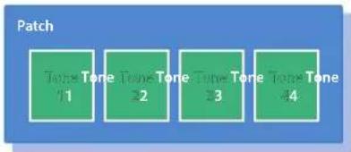
Patches are the basic sound configurations that you play during a performance. Each patch can be configured by combining up to four tones.
Each tone can be turned on/off individually, allowing you to select the tones that will produce sound.
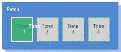
Example 1: A Patch consisting of only one Tone (Tones 2–4 are turned off).
bar
Patch | Category | Value | |---|---| | Tone Tone | 11 | | Tone Tone | 22 | | Tone Tone | 33 | | Tone Tone | 44 |Example 2: A Patch consisting of four Tones.
Tone
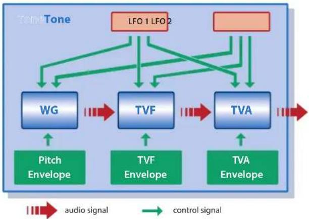
On the SRX ORCHESTRA, the tones are the smallest unit of sound. However, it is not possible to play a tone by itself. The patch is the unit of sound which can be played, and the tones are the basic building blocks which make up the patch.
flowchart
graph TD
    A["LFO 1 LFO 2"] --> B["WG"]
    C[" "] --> D["TVA"]
    B --> E["Pitch Envelope"]
    D --> F["TVF"]
    E --> G["control signal"]
    F --> H["control signal"]
    G --> I["audio signal"]
    H --> J["audio signal"]
    I --> K["control signal"]
    J --> L["audio signal"]
WG (Wave Generator)
Specifies the PCM waveform (wave) that is the basis of the sound, and determines how the pitch of the sound will change.
Specifies how the frequency components of the sound will change.
TVA (Time Variant Amplifier)
Specifies the volume changes and the sound's position in a stereo soundfield.
Envelope
You use Envelope to initiate changes to occur to a sound over time. There are separate envelopes for Pitch, TVF (filter), and TVA (volume).
LFO (Low Frequency Oscillator)
Use the LFO to create cyclic changes (modulation) in a sound. The SRX ORCHESTRA has two LFOs. Either one or both can be applied to effect the WG (pitch), TVF (filter) and/or TVA (volume). When an LFO is applied to the WG pitch, a vibrato effect is produced. When an LFO is applied to the TVF cutoff frequency, a wah effect is produced. When an LFO is applied to the TVA volume, a tremolo effect is produced.
How a Rhythm Set is Structured
Rhythm sets are groups of a number of different percussion instrument sounds.
Since percussion instruments generally do not play melodies, there is no need for a percussion instrument sound to be able to play a scale on the keyboard. It is, however, more important that as many percussion instruments as possible be available to you at the same time.
Therefore, each key (note number) of a rhythm set will produce a different percussion instrument.

flowchart
graph TD
    A["Note number 98 (D7)"] --> B["Note number 97 (C#7)"]
    B --> C["Note number 36 (C2)"]
    C --> D["Note number 35 (B1)"]
    D --> E["Rhythm key (Percussion instrument sound)"]
    E --> F["WG"]
    E --> G["TVF"]
    E --> H["TVA"]
    F --> I["Pitch Envelope"]
    G --> J["TVF Envelope"]
    H --> K["TVA Envelope"]
* There are four wave generators for each rhythm key (percussion instrument sounds).
* LFO is not included in the rhythm keys (percussion instrument sounds).
Calculating the Number of Voices Being Used
The SRX ORCHESTRA is able to play up to 128 notes simultaneously.
The polyphony, or the number of voices (sounds) does not refer only to the number of patches actually being played, but changes according to the number of tones used in the patches, and the number of waves used in the tones. The following method is used to calculate the number of sounds used for one patch being played.
(Number of patches being played) x (Number of tones used by patches being played) x (Number of waves used in the tones)
For example, a patch that combines four tones, each of which use two waves, will use eight notes of polyphony at once. Also, when playing in Performance mode, the number of sounds for each part is counted to obtain the total number of sounds for all parts.
How a Patch Sounds
When the SRX ORCHESTRA is requested to play more than 128 voices simultaneously, currently sounding notes will be turned off to make room for newly requested notes. The note with the lowest priority will be turned off first. The order of priority is determined by the Patch Priority setting (PRIORITY; p. 13).
Patch Priority can be set either to "LAST" or "LOUDEST."
When "LAST" is selected, a newly requested note that exceeds the 128 voice limit will cause the first-played of the currently sounding notes to be turned off.
When "LOUDEST" is selected, the quietest of the currently sounding notes will be turned off. Usually, "LAST" is selected.
About the Effects
The SRX ORCHESTRA has built-in effect units, and you can independently edit each unit's settings.
Multi-Effects
The multi-effects are multi-purpose effects that completely change the sound type by changing the sound itself.
Contained are 78 different effects types; select and use the type that suits your aims.
In addition to effects types composed of simple effects such as Distortion, Flanger, and other such effects, you can also set up a wide variety of other effects, even connecting effects in series or in parallel.
Furthermore, while chorus and reverb can be found among the multi-effect types, the following chorus and reverb are handled with a different system.
Chorus
Chorus adds depth and spaciousness to the sound.
You can select whether to use this as a chorus effect or a delay effect.
Reverb
Reverb adds the reverberation characteristics of halls or auditoriums.
Five different types are offered, so you can select and use the type that suits your purpose.
How effects are handled
The multi-effects, chorus and reverb effects can be set up individually for each patch/rhythm set.
Adjusting the signal level to be sent to each effects unit (Send Level) provides control over the effect intensity that's applied to each tone.

flowchart
graph TD
    A["Patch"] --> B["Term"]
    B --> C["Multi Effects"]
    B --> D["Chorus"]
    B --> E["Reverb"]
    F["Rhythm Set"] --> G["Rhythm Key"]
    G --> H["Multi Effects"]
    G --> I["Chorus"]
    G --> J["Reverb"]
What is a Memory?
Each of the SRX ORCHESTRA's sounds is called a "memory." A memory can be either a "patch" or a "rhythm set."
Bank
1. Click the [BANK] button.
The Memory Select screen (BANK) appears.
![[NEW] button Creates a new empty bank. [DELETE] button Deletes the selected bank. [LOAD] button Loads a bank from a file. [SAVE] button Exports a bank as a file. The selected memory is shown in blue. [WRITE] button Saves an edited sound as a memory in the bank. [RENAME] button Renames the selected memory. [READ] button Loads a memory from a bank. Zoom Drag the bottom-right corner of the window to resize (zoom). A set of 128 memories is called a "bank." By switching banks you can access a large number of memories. A bank of memories can be saved as a file. Bank Memory 01 Memory 02 Memory 03 ... Memory 128 Rhythm Sets have a small symbol at their upper left.](/content/2026/05/1012690/images/03add2549a3d4e5e8d5ed6ee2d7922ec6dff7647524993215efa943b84ffc8ae.jpg)
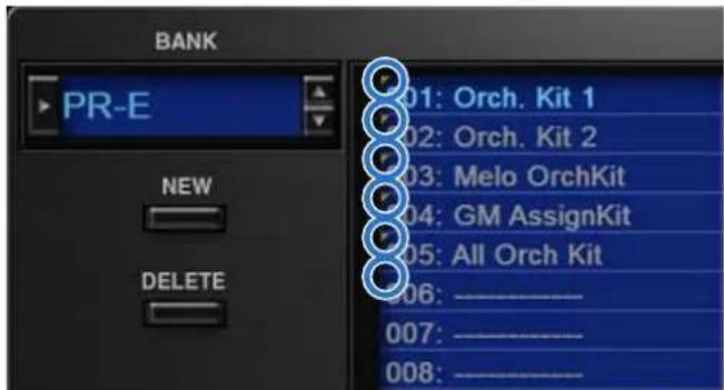
Changing to Other Bank
- Click the Bank field.
The bank list window opens.
- Click the bank that you want to recall.
By pressing the [▲] [▼] buttons located at the right of the bank field, you can switch to the next or previous bank.
Exporting the Bank
Here's how to export a bank as a file.
- Click the [SAVE] button.
The file name input window opens.
- Enter a file name and save.
The file is exported.
Importing a Bank
- Click the [LOAD] button.
The file selection window opens.
- Select a file and load it.
The bank is loaded.
Creating/Deleting a Bank
Creating a bank
Click the [NEW] button to create a new empty bank.
Deleting a bank
Here's how to delete the selected bank.
-
Select a bank as described in "Changing to Other Bank" (p. 8).
-
Click the [DELETE] button.
A confirmation screen appears.
- Click [OK] to delete the bank.
Renaming a Bank
-
Select a bank as described in "Changing to Other Bank" (p. 8).
-
Click ▶ located at the left of the bank field.
-
Edit the name and press the [Return (Enter)] key.
Category
1. Click the [CATEGORY] button.
Memory Select screen (CATEGORY) appears.
![CATEGORY [No Assign] EST (FL Guitar) SBT (Synth Dress) VOX (Vest) PNO (AC Piano) DGY (DIST Guitar) SAX (Star) PLK (Flucked) EP (EL Piano) BS (Base) HLD (Hard Load) ETH (Ethnic) KEY (Keyboard) RBS (Hybrid Base) SLD (Soft Load) PRT (Fitted) BEL (Bell) MLT (Mallet) 100% (Long) FRC (Persception) DRG (Organ) 100% (Long) SPX (Sound FX) ACQ (Accordion) 100% (Long) BTG (BestAG/Wave) DRM (Harmonic) ECT (Tide) BPU (Bright Pair) DFM (Drums) AET1 (AC Guitar) BRS (AC Bass) BPU (Soft Pair) CMB (Combination) 016: SL.Euro Piano 017: JoyoClassics 018: Empathy 019: Piano & Srys 020: Pno Concoro The selected category is shown in blue. The memory belonging to the selected category is shown in the list. The selected memory is shown in blue. [READ] button Loads a memory from a category. Zoom Drag the bottom-right corner of the window to resize (zoom). Zoom = 100%](/content/2026/05/1012690/images/92aac60152de31aa28dd12cf01bbeda5f23de6b126a8f8a08c9a4cccd1b24051.jpg)
Memory
The SRX ORCHESTRA manages 128 memories as one bank.
Loading a Memory
Here's how to load a memory from a bank. When you load a memory, its settings appear in the edit area and can be edited.
- Click the number of the memory that you want to load.
- Click the [READ] button. Or press the [Return (Enter)] key.
The memory is loaded.
* You can also load a memory by double-clicking a memory number.
Saving the Memory
Here's how to save an edited sound as a memory in the bank.
- Click the number of the memory in which you want to save the sound.
- Click the [WRITE] button.
The memory is saved in the bank.
Renaming the Memory
- Click the number of the memory that you want to rename.
- Click the [RENAME] button.
- Change the memory name. (Up to 16 letters)
Changing the Order of the Memories
Drag the memory number to change the order of memories.
Keyboard shortcuts
Keyboard shortcuts for the Patch Select window.
| Key Function | |
| Command (Ctrl) + B | Changes bank |
| Command (Ctrl) + I | Imports bank |
| Command (Ctrl) + E | Exports bank |
| Command (Ctrl) + N | New memory |
| Command (Ctrl) + O | Loads memory |
| Command (Ctrl) + S | Saves memory |
| Up/Down/Left/Right | Selects memory |
| Space | Renames memory |
| Command (Ctrl) + C | Copies memory |
| Command (Ctrl) + V | Pastes memory |
| Delete *1delete ☒ *2fn + delete *2 | Deletes memory |
| Return (Enter) | Loads memory |
| Command (Ctrl) + Z | Undo |
| Command (Ctrl) + Shift + Z | Redo |
| Command (Ctrl) + J | Switches the memory number indication001-12801-1-01-8, 02-1-...-16-8A-1-A-8, B-1-...-P-8 |
| Esc | Closes window |
*1 Windows / *2 Mac
Option
1. Click the [OPTION] button.
2. Select items.
A √ is shown for the selected item.
| Item Explanation | |
| Flip Scroll Direction(Only on Mac) | Inverts the direction of rotation when using the mouse wheel to edit a value. |
| Authentication... Performs user authentication for the SRX ORCHESTRA. | |
Detailed Editing for a Patch (PATCH Parameters)
"Editing" is the process of modifying the values of the SRX ORCHESTRA's various settings (parameters). This chapter explains the procedure for patch editing, and how the patch parameters work.

How to Edit a Patch
You can create a new patch by editing an existing patch.
A patch consists of up to four "tones." Before editing a patch, you should listen to each tone individually to familiarize yourself with the role it plays in creating the overall sound of the patch.
Copying/Pasting Patch Parameters
You can select and copy a portion of the patch parameters (such as a patch tone or MFX), and then paste those parameters to another patch tone or another patch. You can also initialize the settings of a patch or rhythm set.
1. In the main window, click the [UTILITY] button.
A popup appears.
| Item Explanation | |
| Initialize | Initializes the settings of the patch or rhythm set.This is convenient when you want to create data from scratch. |
| Copy | Copies the selected parameters from the currently selected patch or rhythm set to the clipboard. |
| Paste | Pastes the selected parameter from the clipboard to the current patch or rhythm set. |
2. Select "Initialize", "Copy" or "Paste."
A list of the items that can be initialized or copied, or a list of the destinations to which data can be written, appears.
3. In the list, click to select the desired item.
Four tips when creating patches
- Choose a patch that's close to what you have in mind
If you're trying to create a new patch, it will be difficult to make progress if you simply select any old patch and start making changes blindly. It's important to start by selecting a patch that's close to what you have in mind.
- Decide which tones you'll use
When creating a patch, it's very important to decide which tones you're going to use. In the edit screen, use the TONE SWITCH 1–4 settings to specify whether each tone will be heard (on) or silent (off). Turning off unneeded tones is also an important way to conserve polyphony.
● Check the structure setting (p. 15)
The STRUCTURE parameter is a very important one; it specifies how the four tones will be combined. Before you begin actually editing the tones, you must understand the relationship between the tones.
● Turn the effects off (p. 34)
The SRX ORCHESTRA contains a diverse array of effects, allowing you to process the sound in sophisticated ways. Effects have a major impact on the sound, and simply turning off the effects may produce an entirely different impression. Turning off the effects will allow you to hear the sound of the patch itself, which makes it easier to hear the result of the changes you make. In some cases, editing the effect settings may be enough to create the sound you want.
TONE SWITCH/SELECT
Use TONE SWITCH (SW) 1–4 to turn each of the four tones on/off.
Use TONE SELECT 1-4 to select the tone that you want to edit.
[LFO] editing screen
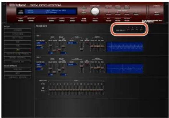
- The parameter window will show the settings of the first selected of the currently selected tones (the button is lit red.).
- You can select multiple tones by clicking a TONE SELECT button while holding down the computer's Shift key.
- You can select all tones by clicking a TONE SELECT button while holding down the computer's Command (Ctrl) key.
- When you edit the settings of a tone, the settings of the currently selected tones will change simultaneously.
[WG+PITCH], [TVF], [TVA], [CONTROL SW] editing screens

- You can select multiple tones by clicking a TONE SELECT button while holding down the computer's Shift key.
- When you edit the settings of a tone, the settings of the currently selected tones will change simultaneously.
- Unselected tones can be edited independently.
Stereo Wave Settings (Set Stereo Function)
Some of the waves that make up a tone key are stereo.
With stereo waves, the name of a left-channel wave ends in "L", while the name of a right-channel wave ends in "R."
The left and right waves are numbered consecutively; the right-channel wave number is one greater than the left-channel wave number.
You can use the following procedure to first select either the left or right wave, and then select the other wave.
- Select a patch.
- Make sure that "WG+PITCH" is selected in the "PATCH" area of the navigation window.
- Use WAVE NUMBER L to select the left-channel wave of the stereo wave.
- While holding down the Command (Ctrl) key, click on WAVE NUMBER R.
The corresponding right-channel wave will be selected.
MEMO
After selecting the right-channel wave in WAVE NUMBER R, you can also hold down the Command (Ctrl) key and click on WAVE NUMBER L to select the left-channel wave. If the wave is not a stereo wave, the selection won't change.
Note when selecting a waveform
The SRX ORCHESTRA uses complex PCM waveforms as the basis for its sounds. For this reason, you should be aware that if you specify a waveform that is very different than the original waveform, the result may not be what you expect.
The SRX ORCHESTRA's internal waveforms can be categorized into the following two types.
One-shot:
These are sounds with a short decay time. One-shot waveforms contain the entire duration of the sound from the attack until it decays to silence. Some of these waveforms capture a complete sound such as a percussion instrument, but there are also many attack component sounds such as the hammer strike of a piano or the fret noise of a guitar.
Loop:
These are sounds with a long decay, or sustaining sounds. Looped waveforms will repeatedly play a portion of a sound once it has reached a relatively stable state. These sounds also include numerous component sounds, such as a vibrating piano string or a resonating pipe.
The following illustration shows an example of a sound created by combining a one-shot waveform with a loop waveform. (This example is of an electric organ.)

Note when selecting a one-shot waveform
It's not possible to use the envelope settings to give a one-shot waveform a longer decay than the original waveform contains, or to make it a sustaining sound. Even if you made this type of envelope setting, you would be trying to bring out something that doesn't exist in the original waveform.
Note when selecting a looped waveform
Many acoustic instruments such as piano or sax are marked by a sudden change in timbre at the very beginning of the sound, and this rapid change is what gives the instrument its distinctive character. When using these waveforms, it's best to use the complex tonal changes in the attack portion of the sound without attempting to modify them; use the envelope only to modify the decay portion of the sound as desired. If you use the envelope to modify the attack as well, the envelope settings will be affected by the attack of the waveform itself, and you may not get the result you intend.
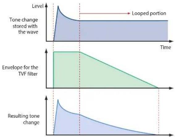
area
| Time Segment | Tone Change Stained with Wave | Envelope for the TVF filter | Resulting Tone Change | | ------------ | ------------------------------ | --------------------------- | --------------------- | | Top Left | Peak | High | Low | | Middle Right | Stable | Decreasing | Decreasing | | Bottom Right | Stable | 0 | 0 |PATCH Parameters
COMMON
PATCH COMMON

Parameter Range/Explanation
| PATCH NAME | Patch name | |
| CATEGORY | Type (category) of the patch | |
| LEVEL | 0-127Volume before passing through MFX/Reverb/ChorusFor distortion-type effects, the tonal character changes depending on the volume that is input.As appropriate for your purpose, adjust this in conjunction with the [MASTER LEVEL] knob. | |
| PAN | L64-0-63RLeft/right position of the patch | |
| OUTPUT ASSIGN | Specifies how the direct sound of each patch will be output.MFX: Output in stereo through multi-effects. You can also apply chorus or reverb to the sound that passes through multi-effects.L+R: Output in stereo to the OUTPUT without passing through the multi-effectL: Output in mono to the OUTPUT L without passing through the multi-effectR: Output in mono to the OUTPUT R without passing through the multi-effectTONE: Outputs according to the settings for each tone. | |
| OCTAVE SHIFT | -3-3Pitch of the patch's sound (in units of an octave) | |
| TUNE | COARSE | -48-48Pitch of the patch's sound (in semitones, +/- 4 octaves) |
| FINE | -50-50Pitch of the patch's sound (in 1-cent steps; one cent is 1/100th of a semitone) | |
| STRETCH TUNE DEPTH | Stretched tuning (a system by which acoustic pianos are normally tuned, causing the lower range to be lower and the higher range to be higher than the mathematical tuning ratios would otherwise dictate)OFF: Equal temperament1-3: Higher settings will produce the greater difference in the pitch of the low and high ranges. | |
Parameter Range/Explanation
Stretched Tuning
Pitch difference from equal temperament

line
| x | Curve 1 | Curve 2 | Curve 3 | | ---- | ------- | ------- | ------- | | OFF | 1 | 2 | 3 |High note range
Low note range
| PITCH BEND RANGE | UP | 0-48Amount of pitch change (in semitones) that occurs when the pitch bend controller is at the maximum position |
| DOWN | -48-0Amount of pitch change (in semitones) that occurs when the pitch bend controller is at the minimum position | |
| MASTER TUNE | 415.3-466.2 HzOverall tuning of the SRX ORCHESTRAThe display shows the frequency of the A4 note (center A). | |
| MASTER KEY SHIFT | -24-+24Shifts the overall pitch of the SRX ORCHESTRA in semitone steps. | |
| OFFSET | CUTOFF | -63-+63CUTOFF (p. 19) |
| RES | -63-+63RES (p. 19) | |
| ATTACK TIME | -63-+63TVF Envelope Time 1, TVA Envelope Time 1 (p. 20, p. 22) | |
| RELEASE TIME | -63-+63TVF Envelope Time 4, TVA Envelope Time 4 (p. 20, p. 22) | |
| VELOCITY SENS | -63-+63Cutoff Velocity Sens, TVA Velocity Sens (p. 20, p. 21) | |
| PRIORITY | How notes will be managed when the maximum polyphony is exceeded (128 voices)LAST: The last-played voices will be given priority (Notes will be turned off in order, beginning with the first-played note.)LOUDEST: The loudest voices will be given priority (Notes will be turned off, beginning with the lowest-volume voice.) | |
| MONO/POLY | MONO: Only the last-played note will sound. This setting is effective when playing a solo instrument patch such as sax or flute.POLY: Two or more notes can be played simultaneously. | |
Parameter Range/Explanation
| LEGATO(*1) | SW | This setting specifies whether the Legato Switch will be used (ON) or not (OFF).LEGATO SW is valid when the Mono/Poly parameter is set to “MONO.”With the LEGATO SW “ON,” pressing a key while continuing to press a previous key causes the note to change pitch to the pitch of the most recently pressed key, sounding all the while.This creates a smooth transition between notes, which is effective when you wish to simulate the hammering-on and pulling-off techniques used by a guitarist. |
| RETRIGGER | The setting determines whether sounds are replayed (ON) or not (OFF) when performing legato. Normally you will leave this parameter “ON.”The LEGATO RETRIGGER is valid when the Mono/ Poly is set to “MONO” and the LEGATO SW is set to “ON.”When “OFF,” when one key is held down and another key is then pressed, only the pitch changes, without the attack of the latter key being played.Set this to “OFF” when performing wind and string phrases or when using modulation with the mono synth keyboard sound. | |
| ANALOG FEEL | 0-127Depth of 1/f modulation (a pleasant and naturally-occurring ratio of modulation that occurs in a babbling brook or rustling wind)* You can simulate the natural instability characteristic of an analog synthesizer by adding this “1/f modulation.” | |
| PORTAMENTO | SW | Specifies whether the portamento effect will be applied (ON) or not (OFF).Portamento is an effect which smoothly changes the pitch from the first-played key to the next-played key. |
| MODE | NORMAL: Portamento will always be applied.LEGATO: Portamento will be applied only when you play legato. | |
| TYPE | RATE: Speed of pitch change is uniform (the time required for the pitch change will correspond to the distance of the pitch change)TIME: The time it takes will be constant, regardless of how far apart in pitch the notes are. | |
| START | PITCH: Start a new portamento from present pitch when another key is pressed while the pitch is changing.NOTE: Portamento will begin anew from the pitch where the current change would end. | |
| TIME | 0-127Specifies the time over which the pitch will change. | |
Parameter Range/Explanation
Portamento Start: PITCH

line
| Time Point | Pitch | | ------------------ | ----- | | press C4 key | C4 | | press C5 key | C5 | | press D4 key | D4 |Portamento Start: NOTE

line
| Time Point | Pitch | | ---------------- | ----- | | press C4 key | C4 | | press C5 key | C5 | | press D4 key | D4 |*1 Let's say you have the LEGATO SW set to "ON," and the LEGATO RETRIGGER set to "OFF." When you try to sound a legato (by pressing a higher key while a lower key is held down), the pitch may sometimes not be able to rise all the way to the intended pitch (stopping instead at an intermediate pitch). This can occur because the limit of pitch rise, as determined on each wave form. Additionally, if differing upper pitch limits are used for the waves of a Patch that uses multiple tones, it may not being heard as MONO. When making large pitch changes, set the LEGATO RETRIGGER to "ON."
PATCH SCALE TUNE

The SRX ORCHESTRA allows you to play the keyboard using temperaments other than equal temperament. The pitch is specified in one-cent units relative to the equal tempered pitch. One-cent is 1/100th of a semitone.
Parameter Range/Explanation
| SCALE TUNESWITCH | OFF, ONTurn this on when you wish to use a tuning scale other than equal temperament. |
Parameter Range/Explanation
| C-B | -64-+63Make scale tune settings for Patch mode. |
Equal Temperament
This tuning divides the octave into 12 equal parts, and is the most widely used method of temperament used in Western music. The SRX ORCHESTRA employs equal temperament when the Scale Tune Switch is set to "OFF."
Just Intonation (Tonic of C)
Compared with equal temperament, the principle triads sound pure in this tuning. However, this effect is achieved only in one key, and the triads will become ambiguous if you transpose.
Arabian Scale
In this scale, E and B are a quarter note lower and C#, F# and G# are a quarter-note higher compared to equal temperament. The intervals between G and B, C and E, F and G#, Bb and C#, and Eb and F# have a neutral third-the interval between a major third and a minor third. On the SRX ORCHESTRA, you can use Arabian temperament in the three keys of G, C and F.
| Note name | Equal temperament | Just intonation (tonic C) | Arabian scale |
| C | 0 0 -6 | ||
| C# | 0 -8 +45 | ||
| D | 0 +4 -2 | ||
| Eb | 0 | +16 | -12 |
| E | 0 | -14 | -51 |
| F | 0 -2 -8 | ||
| F# | 0 | -10 | +43 |
| G | 0 +2 -4 | ||
| G# | 0 | +14 | +47 |
| A | 0 | -16 | 0 |
| Bb | 0 | +14 | -10 |
| B | 0 | -12 | -49 |
STRUCTURE
PATCH STRUCTURE
Structure changes how a tone is sounded.

Parameter Range/Explanation
| TONE 1 & 2, 3 & 4 TYPE | 1–10Determines how tone 1 and 2, or tone 3 and 4 are connected.The following 10 different Types of combination are available. |

flowchart
graph LR
    A["TONE 1 (3)"] --> B["WG"]
    B --> C["TVF"]
    C --> D["TVA"]
    E["TONE 2 (4)"] --> F["WG"]
    F --> G["TVF"]
    G --> H["TVA"]
With this type, tones 1 and 2 (or 3 and 4) are independent. Use this type when you want to preserve PCM sounds or create and combine sounds for each tone.
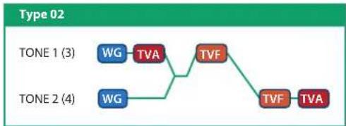
flowchart
graph TD
    A["TONE 1 (3)"] --> B["WG"]
    B --> C["TVA"]
    C --> D["TVF"]
    E["TONE 2 (4)"] --> F["WG"]
    F --> G["TVA"]
    G --> H["TVF"]
    H --> I["TVA"]
This type stacks the two filters together to intensify the characteristics of the filters. The TVA for tone 1 (or 3) controls the volume balance between the two tones.
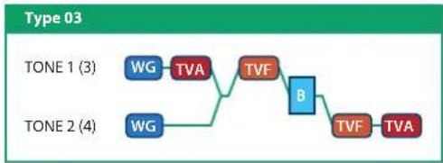
flowchart
graph LR
    A["TONE 1 (3)"] --> B["WG"]
    B --> C["TVA"]
    C --> D["TVF"]
    D --> E["B"]
    E --> F["TVF"]
    F --> G["TVA"]
    H["TONE 2 (4)"] --> I["WG"]
    I --> J["TVA"]
    J --> K["TVF"]
    K --> L["B"]
This type mixes the sound of tone 1 (3) and tone 2 (4), applies a filter, and then applies a booster to distort the waveform.

flowchart
graph LR
    A["TONE 1 (3)"] --> B["WG"]
    C["TONE 2 (4)"] --> D["WG"]
    B --> E["TVA"]
    D --> F["B"]
    E --> G["TVF"]
    F --> H["TVF"]
    G --> I["TVA"]
    H --> J["TVA"]
This type applies a booster to distort the waveform, and then combines the two filters. The TVA for tone 1 (or 3) controls the volume balance between the two tones and adjusts booster level.
Type 05
TONE 1 (3)
TONE 2 (4)
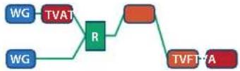
This type uses a ring modulator to create new overtones, and combines the two filters. The tone 1 (3) TVA will control the volume balance of the two tones, adjusting the depth of ring modulator.
Type 06
TONE 1 (3)
TONE 2 (4)

This type uses a ring modulator to create new overtones, and in addition mixes in the sound of tone 2 (4) and stacks the two filters. Since the ring-modulated sound can be mixed with tone 2 (4), tone 1 (3) TVA can adjust the amount of the ring-modulated sound.
Type 07
TONE 1 (3)
TONE 2 (4)

This type applies a filter to tone 1 (3) and ring-modulates it with tone 2 (4) to create new overtones.
Type 08
TONE 1 (3)
TONE 2 (4)

This type sends the filtered tone 1 (3) and tone 2 (4) through a ring modulator, and then mixes in the sound of tone 2 (4) and applies a filter to the result.
Type 09
TONE 1 (3)
TONE 2 (4)

This type passes the filtered sound of each tone through a ring modulator to create new overtones. The tone 1 (3) TVA will control the volume balance of the two tones, adjusting the depth of ring modulator.
Type 10
TONE 1 (3)
TONE 2 (4)

This type passes the filtered sound of each tone through a ring modulator to create new overtones, and also mixes in the sound of tone 2 (4). Since the ring-modulated sound can be mixed with tone 2 (4), tone 1 (3) TVA can adjust the amount of the ring-modulated sound.
* When TYPE 02–10 is selected and one tone of a pair is turned off, the other tone will be sounded as TYPE 01 regardless of the displayed setting.
* If you limit the keyboard area in which a tone will sound (KEY RANGE, p. 25) or limit the range of velocities for which it will sound (VELOCITY RANGE, p. 25), the result in areas or ranges where the tone does not sound is just as if the tone had been turned off. This means that if TYPE 02–10 is selected and you create a keyboard area or velocity range in which one tone of a pair does not sound, notes played in that area or range will be sounded by the other tone as TYPE 01 regardless of the displayed setting.
Parameter Range/Explanation
| TONE 1 & 2, 3 & 4BOOSTER | 0, +6, +12, +18Specifies the amount of boost that is applied (when the Structure Type is 03 or 04)The booster distorts the sound by boosting the input signal, producing the distortion effect that is often used with an electric guitar. Increasing this value will produce stronger distortion. |
Booster
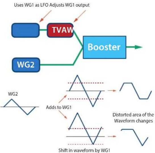
The Booster is used to distort the incoming signal.

In addition to using this other than to create distortion, you can use the waveform (WG1) of one of the tones as an LFO which shifts the other waveform (WG2) upward or downward to create modulation similar to PWM (pulse width modulation).
This parameter works best when you use it in conjunction with the WAVE GAIN parameter (p. 18).
flowchart
graph TD
    A["Uses WG1 as LFO Adjusts WG1 output"] --> B["TVAW"]
    B --> C["Booster"]
    D["WG2"] --> B
    E["Add to WG1"] --> F["Distorted area of the Waveform changes"]
    G["Shift in waveform by WG1"] --> F
Ring Modulator
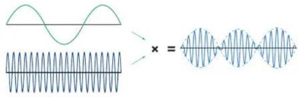
A ring modulator multiplies the waveforms of two tones with each other, generating many new overtones (inharmonic partials) which were not present in either waveform (Unless one of the waveforms is a sine wave, evenly-spaced frequency components will not usually be generated.).
As the pitch difference between the two waveforms changes the harmonic structure, the result will be an unpitched metallic sound. This function is suitable for creating metallic sounds such as bells.
WG + PITCH
PATCH WG
This modifies Waveforms/Pitch Envelope.

Parameter marked with a "★" can be controlled using specified MIDI messages (Matrix Control, p. 26).
Parameter Range/Explanation
| Wave Group | Selects the group for the waveform that is to be the basis of the tone.Standard: Basic wave groupSRX: SRX wave group |
| WAVE NUMBERL (Mono) /R | Off, 1-Basic waveform for a toneWhen in monaural mode, only the left side (L) is specified. When in stereo, the right side (R) is also specified."Set Stereo function"To select a left/right pair of waveforms, select the left (L) WAVE No., and then hold down the Command (Ctrl) key and click the right (R) WAVE No. to recall the right (R) WAVE. |
Parameter Range/Explanation
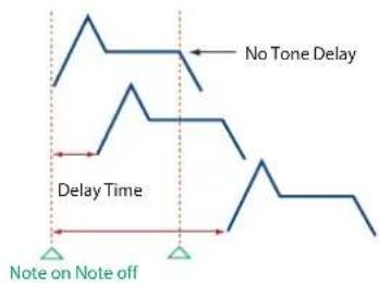
| TONE DELAY MODE (*1) | Type of tone delayNORMAL:The tone begins to play after the time specified in the TONE DELAY TIME parameter has elapsed.HOLD:Although the tone begins to play after the time specified in the TONE DELAY TIME parameter has elapsed, if the key is released before the time specified in the TONE DELAY TIME parameter has elapsed, the tone is not played.KEY-OFF-NORMAL:Rather than being played while the key is pressed, the tone begins to play once the period of time specified in the TONE DELAY TIME parameter has elapsed after release of the key. This is effective in situations such as when simulating noises from guitars and other instruments.KEY-OFF-DECAY:Rather than being played while the key is pressed, the tone begins to play once the period of time specified in the TONE DELAY TIME parameter has elapsed after release of the key. Here, however, changes in the TVA Envelope begin while the key is pressed, which in many cases means that only the sound from the release portion of the envelope is heard.*If you have selected a waveform that is a decay-type sound (i.e., a sound that fades away naturally even if the key is not released), selecting "KEY-OFF-NORMAL" or "KEY-OFF-DECAY" may result in no sound being heard. |
| TONE DELAY TIME (*1) | 0–127, NoteTime from when the key is pressed (or if the Tone Delay Mode parameter is set to "KEY-OFF-NORMAL" or "KEY-OFF-DECAY," the time from when the key is released) until when the tone will sound Specify this as a note value if you want to synchronize the delay to the tempo of the SRX ORCHESTRA. |
*1 This produces a time delay between the moment a key is pressed (or released), and the moment the tone actually begins to sound. You can also make settings that shift the timing at which each tone is sounded. This differs from the Delay in the internal effects, in that by changing the sound character of the delayed tones and changing the pitch for each tone, you can also perform arpeggio-like passages just by pressing one key.
You can also synchronize the tone delay time to the tempo of the SRX ORCHESTRA.
- If you are not going to use Tone Delay, set the TONE DELAY MODE parameter to "NORMAL" and DELAY TIME parameter to "0."
- If STRUCTURE (p. 15) is set to TYPE 02–10, the settings for tone 1 (3) will follow the settings of tone 2 (4). (This is because the outputs of tones 1 and 2 are combined into tone 2, and the outputs of tones 3 and 4 are combined into tone 4.)
* The following illustration shows the operation of "TVA Env."
Tone Delay Mode: NORMAL
Tone Delay Mode: HOLD
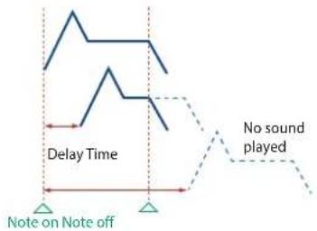
Tone Delay Mode: KEY-OFF-NORMAL

Tone Delay Mode: KEY-OFF-DECAY

Parameter Range/Explanation
| GAIN | -6, 0, +6, +12Gain (amplification) of the waveformThe value changes in 6 dB (decibel) steps—an increase of 6 dB doubles the waveform's gain.* If you intend to use the Booster to distort the waveform's sound, set this parameter to its maximum value (p. 16). | |
| TEMPO SYNC | Turn this "ON" if you want the Phrase Loop to match the tempo of the DAW.* When this parameter is set to "ON," set the TONE DELAY TIME parameter (p. 17) to "0." | |
| FXM (*2) | ON | This sets whether FXM will be used (ON) or not (OFF). |
| COLOR | 1-4How FXM will perform frequency modulationHigher settings result in a grainier sound, while lower settings result in a more metallic sound. | |
| DEPTH ★ | 0-16Depth of the modulation produced by FXM | |
| TUNE | COARSE ★ | -48-+48Pitch of the tone's sound (in semitones, +/-4 octaves) |
| FINE ★ | -50-+50Pitch of the tone's sound (in 1-cent steps; one cent is 1/100th of a semitone) | |
| RANDOM PITCH | 0-1200Width of random pitch deviation that will occur each time a key is pressed (in 1-cent steps)If you do not want the pitch to change randomly, set this to "0." | |
| PITCH KF(Pitch Keyfollow) | -200-+200Amount of pitch change that will occur when you play a key one octave higherIf you want the pitch to rise one octave as on a conventional keyboard, set this to "+100." If you want the pitch to rise two octaves, set this to "+200." | |
*2 FXM (Frequency Cross Modulation) uses a specified waveform to apply frequency modulation to the currently selected waveform, creating complex overtones. This is useful for creating dramatic sounds or sound effects.
PITCH ENV (WAVE PITCH ENVELOPE
Parameter marked with a “★” can be controlled using specified MIDI messages. (Matrix Control, p. 26).
| Parameter Range/Explanation | |
| DEPTH | -12-+12Depth of the Pitch envelopeHigher settings will cause the pitch envelope to produce greater change. Negative (-) settings will invert the shape of the envelope. |
| TIME KF(Time Keyfollow) | -100-+100Use this setting if you want the pitch envelope times (T2-T4) to be affected by the keyboard location.Based on the pitch envelope times for the C4 key, positive (+) settings will cause notes higher than C4 to have increasingly shorter times. |
| VEL SENS(Velocity Sens) | -63-+63Keyboard playing dynamics can be used to control the depth of the pitch envelope.If you want the pitch envelope to have more effect for strongly played notes, set this parameter to a positive (+) value. |
| T1 SENS(T1 Velocity Sens) | -63-+63This allows keyboard dynamics to affect the T1 of the Pitch envelope.If you want T1 to be speeded up for strongly played notes, set this parameter to a positive (+) value. |
| T4 SENS(T4 Velocity Sens) | -63-+63Use this parameter when you want key release speed to affect the T4 value of the Pitch envelope.If you want T4 to be speeded up for quickly released notes, set this parameter to a positive (+) value. |
| T1-4 ★(Time 1-4) | 0-127Pitch envelope times (T1-T4)Higher settings will result in a longer time until the next pitch is reached. |
| L0-4(Level 0-4) | -63-+63Pitch envelope levels (L0-L4)Specify how the pitch will change at each point, relative to the pitch set with COARSE TUNE or FINE TUNE. |
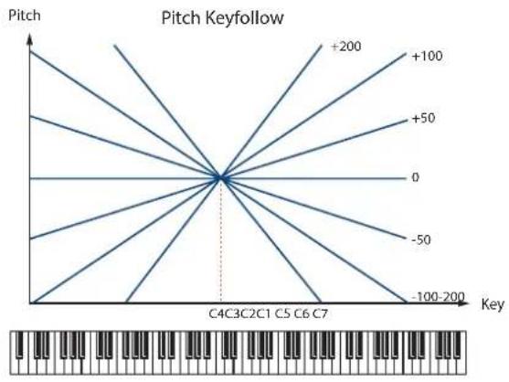
line
| Key | Pitch | | ------- | ----- | | 0 | +200 | | 0 | +100 | | 0 | +50 | | 0 | 0 | | 0 | -50 | | 0 | -100 | | 0 | -100 | | 0 | -100 | | 0 | -100 | | 0 | -100 | | 0 | -100 | | 0 | -100 | | 0 | -100 | | 0 | -100 | | 0 | -100 |
line
| Time | Pitch | |------|-------| | L0 | 0 | | L1 | 1 | | L2 | -1 | | L3 | 1 | | L4 | -1 |TVF
PATCH TVF
A filter cuts or boosts a specific frequency region to change a sound's brightness, thickness, or other qualities.

| Parameter | Range/Explanation |
| FILTER TYPE | Type of filterOFF: No filter is used.LPF: Low Pass Filter. This reduces the volume of all frequencies above the Cutoff Frequency in order to round off, or un-brighten the sound.BPF: Band Pass Filter. This leaves only the frequencies in the region of the Cutoff Frequency, and cuts the rest. This can be useful when creating distinctive sounds.HPF: High Pass Filter. This cuts the frequencies in the region below the Cutoff Frequency. This is suitable for creating percussive sounds emphasizing their higher tones.PKG: Peaking Filter. This emphasizes the frequencies in the region of the Cutoff Frequency. You can use this to create wah-wah effects by employing an LFO to change the Cutoff Frequency cyclically.LPF2: Low Pass Filter 2. Although frequency components above the Cutoff Frequency are cut, the sensitivity of this filter is half that of the LPF. This filter is good for use with simulated instrument sounds such as the acoustic piano.LPF3: Low Pass Filter 3. Although frequency components above the Cutoff Frequency are cut, the sensitivity of this filter changes according to the Cutoff Frequency. While this filter is also good for use with simulated acoustic instrument sounds, the nuance it exhibits differs from that of the LPF2, even with the same TVF Envelope settings.* If you set "LPF2" or "LPF3," the setting for the RES parameter will be ignored. |
| CUTOFF ★(Cutoff Frequency) | 0-127Frequency at which the filter begins to have an effect on the waveform's frequency components |
| RES ★(Resonance) | 0-127Emphasizes the portion of the sound in the region of the cutoff frequency, adding character to the sound* Excessively high settings can produce oscillation, causing the sound to distort. |
| RES VEL SENS(Resonance Velocity Sens) | -63-+63This allows keyboard velocity to modify the amount of Resonance.If you want strongly played notes to have a greater Resonance effect, set this parameter to positive (+) settings. |
Parameter Range/Explanation
| CUTOFF KF(Cutoff Keyfollow) | -200-+200Use this parameter if you want the cutoff frequency to change according to the key that is pressedRelative to the cutoff frequency at the C4 key (center C), positive (+) settings will cause the cutoff frequency to rise for notes higher than C4, and negative (-) settings will cause the cutoff frequency to fall for notes higher than C4. Larger settings will produce greater change. |
Resonance

line
| Parameter Value | Peak Position (approx.) | | --------------- | ------------------------ | | High | Peak | | Cutoff frequency | Peaks | | Low | Peaks |Cutoff Keyfollow
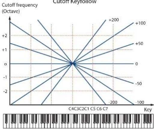
Parameter Range/Explanation
| VEL CURVE(Cutoff Velocity Curve) | FIX, 1-7Curve that determines how keyboard playing dynamics (velocity) will affect the cutoff frequencySet this to “FIX” if you don't want the Cutoff frequency to be affected by the keyboard velocity. |
| FIX 1 2 34 5 6 7 | |
| VEL SENS(Cutoff Velocity Sens) | -63-+63Use this parameter when changing the cutoff frequency to be applied as a result of changes in playing velocity.If you want strongly played notes to raise the cutoff frequency, set this parameter to positive (+) settings. |
FILTER ENV (TVF ENVELOPE)
Parameter marked with a “★” can be controlled using specified MIDI messages (Matrix Control, p. 26).
| Parameter Range/Explanation | |
| DEPTH | -63-+63Depth of the TVF envelopeHigher settings will cause the TVF envelope to produce greater change. Negative (-) settings will invert the shape of the envelope. |
| TIME KF(Time Keyfollow) | -100-+100Use this setting if you want the TVF envelope times (T2-T4) to be affected by the keyboard location.Based on the TVF envelope times for the C4 key (center C), positive (+) settings will cause notes higher than C4 to have increasingly shorter times. |
| VEL CURVE(Velocity Curve) | FIX, 1-7Curve that determines how keyboard playing dynamics (velocity) will affect the TVF envelope Set this to “FIX” if you don’t want the TVF Envelope to be affected by the keyboard velocity.FIX 1 2 34 5 6 7 |
| VEL SENS(Velocity Sens) | -63-+63Specifies how keyboard playing dynamics will affect the depth of the TVF envelope.Positive (+) settings will cause the TVF envelope to have a greater effect for strongly played notes, and negative (-) settings will cause the effect to be less. |
| T1 SENS | -63-+63This allows keyboard dynamics to affect the T1 of the TVF envelope.If you want T1 to be speeded up for strongly played notes, set this parameter to a positive (+) value. |
| T4 SENS | -63-+63Use this parameter when you want key release speed to affect the T4 value of the TVF envelope.If you want T4 to be speeded up for quickly released notes, set this parameter to a positive (+) value. |
| T1-4 ★(Time 1-4) | 0-127TVF envelope times (T1-T4)Higher settings will lengthen the time until the next cutoff frequency level is reached. |
| L0-4(Level 0-4) | 0-127TVF envelope levels (L0-L4)Specify how the cutoff frequency will change at each point, relative to the Cutoff Frequency value. |
TVF Envelope

line
| Time | Cutoff frequency | |------|------------------| | L0 | 0 | | L1 | Peak (T1) | | L2 | Low | | L3 | Mid | | L4 | Low |
line
| Key | Delay Time | | --- | --- | | -100 | 0 | | -50 | 0 | | 0 | 0 | | +50 | 0 | | +100 | 0 |TVA
PATCH TVA
TVA adjusts the volume.

Parameter marked with a “★” can be controlled using specified MIDI messages (Matrix Control, p. 26).
| Parameter Range/Explanation | |
| LEVEL ★ | 0-127Volume of the toneThis setting is useful primarily for adjusting the volume balance between tones. |
| VEL CURVE(Velocity Curve) | FIX, 1-7Curve that determines how keyboard playing dynamics (velocity) will affect the volumeSet this to “FIX” if you don’t want the volume of the tone to be affected by the keyboard velocity.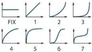 |
| VEL SENS(Velocity Sens) | -63-+63Set this when you want the volume of the tone to change depending on keyboard playing dynamicsSet this to a positive (+) value to have the changes in tone volume increase the more forcefully the keys are played; to make the tone play more softly as you play harder, set this to a negative (-) value. |
Parameter Range/Explanation
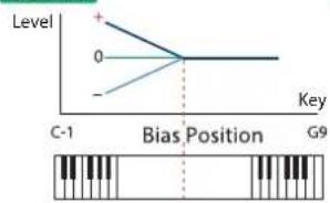
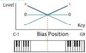
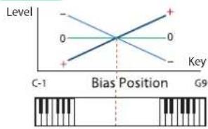
| BIAS(*1) | LEVEL | -100-+100Angle of the volume change that will occur in the selected Bias DirectionLarger settings will produce greater change.Negative (-) values will invert the change direction. |
| POSITION | C-1-G9Key relative to which the volume will be modified | |
| DIRECTION | Direction in which change will occur starting from the Bias PositionLOWER:The volume will be modified for the keyboard area below the Bias Position.UPPER:The volume will be modified for the keyboard area above the Bias Position.LO&UP:The volume will be modified symmetrically toward the left and right of the Bias Position.ALL:The volume changes linearly with the Bias Position at the center. |
*1 Bias causes the volume to be affected by the keyboard position. This is useful for changing volume through keyboard position (pitch) when playing acoustic instruments.
LOWER
UPPER

LO&UP
ALL
Parameter Range/Explanation
| PAN ★ | L64-0-63RLeft/right position of the tone |
| PAN KF(Pan Keyfollow) | -100-+100Use this parameter if you want key position to affect panning.Positive (+) settings will cause notes higher than C4 key (center C) to be panned increasingly further toward the right, and negative (-) settings will cause notes higher than C4 key (center C) to be panned toward the left. Larger settings will produce greater change. |
| RANDOM PAN DEPTH | 0-63Use this parameter when you want the stereo location to change randomly each time you press a key.Higher settings will produce a greater amount of change. |
Parameter Range/Explanation
| ALT. PAN DEPTH(Alternate Pan Depth) | L63-0-63RThis setting causes panning to be alternated between left and right each time a key is pressed.Higher settings will produce a greater amount of change. "L" or "R" settings will reverse the order in which the pan will alternate between left and right. For example if two tones are set to "L" and "R" respectively, the panning of the two tones will alternate each time they are played. |

line
| Key | R | Value | |-----|------|-------| | 0 | 0 | 0 | | 100 | 0 | +100 | | 200 | 0 | +50 | | 300 | 0 | 0 | | 400 | 0 | -50 | | 500 | 0 | -100 | | 600 | 0 | -100 | | 700 | 0 | -100 | | 800 | 0 | -100 | | 900 | 0 | -100 | | 1000| 0 | -100 |* When a TYPE 02–10 has been selected for STRUCTURE (p. 15), the settings for PAN KF, RANDOM PAN DEPTH, and ALT. PAN DEPTH for tone 1 (3) will be in concord with the settings for tone 2 (4). (This is because the outputs of tones 1 and 2 are consolidated in tone 2, and the outputs of tones 3 and 4 are consolidated in tone 4.)
AMP ENV (TVA ENVELOPE)
Parameter marked with a “★” can be controlled using specified MIDI messages (Matrix Control, p. 26).
Parameter Range/Explanation
| TIME KF (TIME Keyfollow) | -100-+100 Use this setting if you want the TVA envelope times (T2-T4) to be affected by the keyboard location. Based on the TVA envelope times for the C4 key (center C), positive (+) settings will cause notes higher than C4 to have increasingly shorter times, and negative (-) settings will cause them to have increasingly longer times. Larger settings will produce greater change. |
| T1 SENS | -63-+63 This allows keyboard dynamics to affect the T1 of the TVA envelope. If you want Time 1 to be speeded up for strongly played notes, set this parameter to a positive (+) value. If you want it to be slowed down, set this to a negative (-) value. |
| T4 SENS | -63-+63 Use this parameter when you want key release speed to affect the T4 value of the TVA envelope. If you want T4 to be speeded up for quickly released notes, set this parameter to a positive (+) value. If you want it to be slowed down, set this to a negative (-) value. |
| T1-4 ★ (Time 1-4) | 0-127 TVA envelope times (T1-T4) Higher settings will lengthen the time until the next volume level is reached. |
Parameter Range/Explanation
| L1-3(Level 1-3) | 0-127TVA envelope levels (L1-L3)Specifies the volume at each point. |
TVA Envelope

line
| Time | Level | |------|-------| | T1 | + | | L1 | Peak | | L2 | Low | | L3 | Low | | T3 | + | | T4 | + | | Note on | 0 | | Note off | 0 |
line
| Key | Time | | --- | ---- | | -100 | 0 | | -50 | 0 | | 0 | 0 | | +50 | 0 | | +100 | 0 |OUTPUT
Parameter Range/Explanation
| SEND LEVEL OUT(Output Level) | 0-127Level of the signal that is sent to the outputdestination specified by OUTPUT ASSIGN |
SEND LEVEL (OUTPUT ASSIGN = MFX)
| CHO(Chorus Send) | 0-127Level of the signal sent to chorus for each tone if the tone is sent through MFX |
| REV(Reverb Send) | 0-127Level of the signal sent to reverb for each tone if the tone is sent through MFX |
SEND LEVEL (OUTPUT ASSIGN = non MFX)
| CHO(Chorus Send) | 0-127Level of the signal sent to chorus for each tone if the tone is not sent through MFX |
| REV(Reverb Send) | 0-127Level of the signal sent to reverb for each tone if the tone is not sent through MFX |
Parameter Range/Explanation
| OUTPUT ASSIGN | Specifies how the direct sound of each tone will be output.MFX: Output in stereo through multi-effects. You can also apply chorus or reverb to the sound that passes through multi-effects.L+R: Output in stereo to the OUTPUT without passing through the multi-effectL: Output in mono to the OUTPUT L without passing through the multi-effectR: Output in mono to the OUTPUT R without passing through the multi-effect* If the PATCH OUTPUT ASSIGN is set to anything other than "TONE," these settings will be ignored,* If "STRUCTURE" (p. 15) is set to TYPE 02-10, the settings for tone 1 (3) will follow the settings of tone 2 (4). (This is because the outputs of tones 1 and 2 are combined into tone 2, and the outputs of tones 3 and 4 are combined into tone 4.)* Sounds are output to chorus and reverb in mono at all times.* The output destination of the signal after passing through the chorus is set with the CHORUS OUTPUT SELECT (p. 34). |
LFO
An LFO (Low Frequency Oscillator) causes change over a cycle in a sound. Each tone has two LFOs (LFO1/LFO2), and these can be used to cyclically change the pitch, cutoff frequency and volume to create modulation-type effects such as vibrato, wah and tremolo. Both LFOs have the same parameters so only one explanation is needed.

PATCH LFO
LFO 1/LFO 2
Parameter marked with a “★” can be controlled using specified MIDI messages (Matrix Control, p. 26).
Parameter Range/Explanation
| WAVEFORM | Waveform of the LFOSIN:Sine waveTRI:Triangle waveSAW-UP:Sawtooth waveSAW-DW:Sawtooth wave (negative polarity)SQR:Square waveRND:Random waveBEND-UP:Once the attack of the waveform output by the LFO is allowed to develop in standard fashion, the waveform then continues without further change.BEND-DW:Once the decay of the waveform output by the LFO is allowed to develop in standard fashion, the waveform then continues without further change.TRP:Trapezoidal waveS&H:Sample & Hold wave (holds a random value during each cycle)CHS:Chaos waveVSIN:Modified sine wave. The amplitude of a sine wave is randomly varied once each cycle.STEP:A waveform generated by the data specified by LFO Step 1–16. This produces stepped change with a fixed pattern similar to a step modulator.* If you set this to “BEND-UP” or “BEND-DW,” you must turn the KEY TRIGGER parameter (p. 24) to “ON.” If this is “OFF,” it will have no effect. |
| OFFSET | -100–+100Raises or lowers the LFO waveform relative to the central value (pitch or cutoff frequency).Positive (+) settings will move the waveform so that modulation will occur from the central value upward. Negative (-) settings will move the waveform so that modulation will occur from the central value downward. |
| RATE VALUE ★ | 0–127, NoteModulation speed of the LFOIf you want the LFO rate to be synchronized with the tempo, this should be set in terms of a note value.* This setting will be ignored if the Waveform parameter is set to “CHS.” |
| RATE DETUNE | 0–127Makes subtle changes in the LFO cycle rate (Rate parameter) each time a key is pressed.Higher settings will cause greater change.* This parameter is invalid when RATE VALUE is set to “note.” |
| DELAY TIME | 0–127Time elapsed before the LFO effect is applied (the effect continues) after the key is pressed (or released)When using violin, wind, or certain other instrument sounds in a performance, rather than having vibrato added immediately after the sounds are played, it can be effective to add the vibrato after the note is drawn out somewhat.* Set this according to your purpose as described in “How to Apply the LFO” (p. 24). |
Parameter Range/Explanation
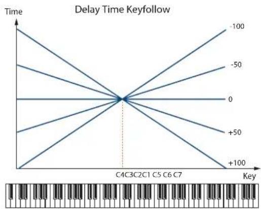
| DELAY KEYFOLLOW(Delay Time Keyfollow) | -100~+100Adjusts the value for the DELAY TIME parameter depending on the key position, relative to the C4 key (center C).If this is set to a positive "+" value, the DELAY TIME will become shorter as you play notes higher than the C4 key (middle C). |
line
| Key | Delay Time | | --- | --- | | 0 | 0 | | +100 | -100 | | +50 | -50 | | -50 | -100 | | -100 | -50 | | +100 | 0 | | +50 | +50 | | -50 | +100 | | 0 | 100 | | +100 | 100 | | +50 | 100 | | -100 | 100 | | 100 | 100 |Parameter marked with a "★" can be controlled using specified MIDI messages (Matrix Control, p. 26).
Parameter Range/Explanation
| FADE MODE | ON-IN, ON-OUT, OFF-IN, OFF-OUTHow the LFO will be applied* Set this according to your purpose as described in"How to Apply the LFO" (p. 24). |
| FADE TIME | 0–127Time over which the LFO amplitude will reach the maximum (minimum)* Set this according to your purpose as described in"How to Apply the LFO" (p. 24). |
| KEY TRIGGER | OFF, ONSpecifies whether the LFO cycle will be synchronized to begin when the key is pressed (ON) or not (OFF). |
| DEPTH PITCH ★ | -63–+63How deeply the LFO will affect pitch |
| DEPTH TVF ★ | -63–+63How deeply the LFO will affect the cutoff frequency |
| DEPTH TVA ★ | -63–+63How deeply the LFO will affect the volume |
| DEPTH PAN ★ | -63–+63How deeply the LFO will affect the pan |
Positive (+) and negative (-) settings for the DEPTH parameters result in differing kinds of change in pitch and volume. For example, if you set the DEPTH parameter to a positive (+) value for one tone, and set another tone to the same numerical value, but make it negative (-), the modulation phase for the two tones will be the reverse of each other. This allows you to shift back and forth between two different tones, or combine it with the Pan setting to cyclically change the location of the sound image.
* If "STRUCTURE" (p. 15) is set to TYPE 02-10, the settings for tone 1 (3) will follow the settings of tone 2 (4). (This is because the outputs of tones 1 and 2 are combined into tone 2, and the outputs of tones 3 and 4 are combined into tone 4.)
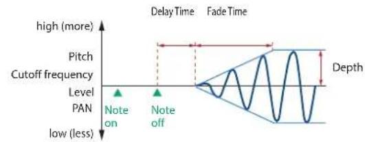
How to Apply the LFO
Apply the LFO gradually after the key is pressed

line
| Level | Value | | ----------- | ----- | | high (more) | High | | low (less) | Low | | Cutoff frequency | Not labeled as "Note on" | | Level | Not labeled as "Note on" | | PAN | Not labeled as "Note on" | | Depth | Not labeled as "Depth" |FADE MODE: ON-IN
DELAY TIME: Time from when the keyboard is played until the LFO begins to be applied
FADE TIME: Time over which the LFO amplitude will reach the maximum after the DELAY TIME has elapsed
Apply the LFO immediately when the key is pressed, and then gradually begin to decrease the effect

line
| Level | Value | | ----------- | ----- | | high (more) | 1 | | low (less) | 0 | | Cutoff frequency | Peak | | Level | 0 | | PAN | 0 |FADE MODE: ON-OUT
DELAY TIME: Time that the LFO will continue after the keyboard is played
FADE TIME: Time over which the LFO amplitude will reach the minimum after the DELAY TIME has elapsed
Apply the LFO gradually after the key is released
line
| Level | Note on | Note off | |-------|---------|----------| | high | | | | low | | |FADE MODE: OFF-IN
DELAY TIME: Time from when the keyboard is released until the LFO begins to be applied
FADE TIME: Time over which the LFO amplitude will reach the maximum after the DELAY TIME has elapsed
Apply the LFO from when the key is pressed until it is released, and gradually begin to decrease the effect when the key is released

line
| Level | Note on | Note off | |-------|---------|----------| | Low | - | - | | Level | - | - | | PAN | - | - | | Level | - | - | | High | - | - |FADE MODE: OFF-OUT
DELAY TIME: Time that the LFO will continue after the keyboard is released
FADE TIME: Time over which the LFO amplitude will reach the minimum after the DELAY TIME has elapsed
STEP LFO
| Parameter Range/Explanation | |
| STEP TYPE | When generating an LFO waveform from the data specified in LFO Step 1-16, specify whether the level will change abruptly at each step or will be connected linearly.TYPE1: stair-step changeTYPE2: linear change |
| STEP 1-16 | -36-+36Specifies the data for the Step LFO.If the LFO PITCH DEPTH is +63, each +1 unit of the step data corresponds to a pitch of +50 cents. |
VELOCITY & KEY RANGE
PATCH VELOCITY RANGE
You can use the force with which keys are played to control the way each Tone is played.


| Parameter Range/Explanation | |
| VELOCITY CONTROL | OFF, ON, RANDOM, CYCLEDetermines whether a different tone is played (ON) or not (OFF) depending on the force with which the key is played (velocity).RANDOM:The patch's constituent tones will sound randomly, regardless of any Velocity.CYCLE:The patch's constituent tones will sound consecutively, regardless of any Velocity. |
| TMT CONTROL SW | OFF, ONUse the Matrix Control (p. 26) to enable (ON), or disable (OFF) sounding of different tones. |
| FADE LOWER | 0–127Determines what will happen to the tone's level when the tone is played at a velocity lower than Velocity Range Lower.If you don't want the tone to sound at all, set this parameter to "0." |
| LOWER | 1-(UPPER)Specifies the lowest velocity at which the tone will sound. |
| UPPER | (LOWER) -127Specifies the highest velocity at which the tone will sound. |
| FADE UPPER | 0–127Determines what will happen to the tone's level when the tone is played at a velocity greater than Velocity Range Upper.If you don't want the tone to sound at all, set this parameter to "0." |
MEMO
When using the Matrix Control to have different tones played, set the lowest value (LOWER) and highest value (UPPER) of the value of the MIDI message used.
NOTE
Instead of using Velocity, you can also have tones substituted using the Matrix Control. However, the keyboard velocity and the Matrix Control cannot be used simultaneously to make different tones to sound. When using the Matrix Control to switch tones, set the VELOCITY CONTROL parameter to "OFF."
PATCH KEY RANGE
You can use the note number to control the way each Tone is played.


Parameter Range/Explanation
| FADE LOWER | 0-127Determines what will happen to the tone's level when a note that's lower than Key Range Lower is played.If you don't want the tone to sound at all, set this parameter to "0." |
| LOWER | C-1-(UPPER)Specifies the lowest note that the tone will sound for each tone. |
| UPPER | (LOWER)-G9Specifies the highest note that the tone will sound for each tone. |
| FADE UPPER | 0-127Determines what will happen to the tone's level when a note that's higher than Key Range Upper is played.If you don't want the tone to sound at all, set this parameter to "0." |
MATRIX CONTROL
The function which allows you use MIDI messages to make changes in realtime to the tone parameters is called the Matrix Control. Up to four Matrix Controls can be used in a single patch.
To use the Matrix Control, specify which MIDI message (SOURCE) will be used to control which parameter (DESTINATION), and how greatly (SENS), and the tone to which the effect is applied (TONE).

Parameter Range/Explanation
| SOURCE 1-4 | MIDI message used to change the tone parameter with the Matrix ControlOFF:Matrix control will not be used.CC01-31, 33-95:Controller numbers 1-31, 33-95PITCH BEND:Pitch BendAFTERTOUCH:AftertouchVELOCITY:Pressure you press a key withKEYFOLLOW:Keyboard position with C4 as 0TEMPO:The tempo of the DAWLFO1:LFO 1LFO2:LFO 2PITCH ENV:Pitch envelopeTVF ENV:TVF envelopeTVA ENV:TVA envelope |
MEMO
• VELOCITY and KEYFOLLOW correspond to Note messages.
- Although there are no MIDI messages for LFO 1 through TVA Envelope, they can be used as Matrix Control. In this case, you can change the tone settings in realtime by playing patches.
NOTE
If RCV BENDER, RCV EXP, or RCV HOLD-1 (p. 26–p. 27) are "ON," incoming MIDI messages of these types will affect the Pitch Bend, Expression, or Hold 1 settings at the same time that they affect the target parameter (DESTINATION). If you want these incoming messages to affect only the target parameter, turn these settings "OFF."
Parameter Range/Explanation
| DESTINATION 1-4 | OFF, PITCH, CUTOFF, RESONANCE, LEVEL, PAN, OUTPUT LEVEL, CHORUS SEND, REVERB SEND, LFO1/2 PCH DEPTH, LFO1/2 TVF DEPTH, LFO1/2 TVA DEPTH, LFO1/2 PAN DEPTH, LFO1/2 RATE, PCH ENV A-TIME, PCH ENV D-TIME, PCH ENV R-TIME, TVF ENV A-TIME, TVF ENV D-TIME, TVF ENV R-TIME, TVA ENV A-TIME, TVA ENV D-TIME, TVA ENV R-TIME, TMT, FXM DEPTH, MFX-CTRL1-4 Tone parameters that are to be controlled when using the Matrix Control Up to four parameters can be specified for each Matrix Control, and controlled simultaneously. * In this manual, parameters that can be controlled using the Matrix Control are marked with a “★.” |
| SENS 1-4 | -63--+63 Amount of the Matrix Control's effect that is applied If you wish to modify the selected parameter in a positive (+) direction—i.e., a higher value, toward the right, or faster etc.—from its current setting, select a positive (+) value. If you wish to modify the selected parameter in a negative (-) direction—i.e., a lower value, toward the left, or slower etc.—from its current setting, select a negative (-) value. For either positive or negative settings, greater absolute values will allow greater amounts of change. Set this to “0” if you don't want to apply the effect. |
| TONE 1-4 (Tone Switch 1-4) | Tone to which the effect is applied when using the Matrix Control OFF: The effect will not be applied. ON: The effect will be applied. REV: The effect will be applied in reverse. |
CONTROL SW

Parameter Range/Explanation
| RCV BENDER(Receive Bender) | OFF, ONFor each tone, specify whether MIDI Pitch Bend messages will be received (ON), or not (OFF). |
| RCV EXP(Receive Expression) | OFF, ONFor each tone, specify whether MIDI Expression messages will be received (ON), or not (OFF). |
| Parameter Range/Explanation | |
| RCV HOLD-1(Receive Hold-1) | OFF, ONFor each tone, specify whether MIDI Hold-1 messages will be received (ON), or not (OFF).* If "NO-SUS" is selected for ENV MODE parameter, this setting will have no effect. |
| REDAMPER | OFF, ONYou can specify, on an individual tone basis, whether or not the sound will be held when a Hold 1 message is received after a key is released, but before the sound has decayed to silence.If you want to sustain the sound, set this "ON." This function is effective for piano sounds.* In order to use this function, you must also set RCV HOLD-1 to "ON." |
| RCV PAN MODE(Receive Pan Mode) | CONTINUOUS, KEY-ONFor each tone, specify how pan messages will be received.CONTINUOUS: Whenever Pan messages are received, the stereo position of the tone will be changed.KEY-ON: The pan of the tone will be changed only when the next note is played. If a pan message is received while a note is sounding, the panning will not change until the next key is pressed.* The channels cannot be set so as not to receive Pan messages. |
| ENV MODE(Envelope Mode) | NO-SUS, SUSTAINWhen a loop waveform (p. 12) is selected, the sound will normally continue as long as the key is pressed. If you want the sound to decay naturally even if the key remains pressed, set this to "NO-SUS."* If a one-shot type wave (p. 12) is selected, it will not sustain even if this parameter is set to "SUSTAIN." |
How to Edit a Rhythm Set
You can create a new rhythm set by editing an existing rhythm set. A rhythm set is a collection of rhythm keys (percussion instrument sounds). To edit a rhythm set, you need to edit the settings of the rhythm key assigned to each key.
The rhythm key assigned to each key consists of up to four waves.
The relationship between rhythm keys and waves is the same as the relationship between patches and tones.
Copying/Pasting Rhythm Parameters
You can select and copy a portion of the rhythm parameters (such as a rhythm key or MFX), and then paste those parameters to another rhythm key or another patch.
1. In the main window, click the [UTILITY] button.
A popup appears.
| Item Explanation | |
| Initialize | Initializes the settings of the patch or rhythm set.This is convenient when you want to create data from scratch. |
| Copy | Copies the selected parameter from the currently selected patch or rhythm set to the clipboard. |
| Paste | Pastes the selected parameter from the clipboard to the current patch or rhythm set. |
2. Select "Initialize", "Copy" or "Paste."
A list of the items that can be initialized or copied, or a list of the destinations to which data can be written, appears.
3. In the list, click to select the desired item.
WG
Use TONE SWITCH (SW) 1–4 to turn each of the four waves on/off.
Use TONE SELECT 1–4 to select the wave that you want to edit.

- You can select multiple waves by clicking a TONE SWITCH button while holding down the computer's Shift key.
- You can select all waves by holding down the computer's Command (Ctrl) key and clicking a TONE SWITCH button.
- When you edit the settings of a wave, the settings of the currently selected waves will change simultaneously.
- Unselected waves can be edited independently.
Stereo Wave Settings (Set Stereo Function)
Some of the waves that make up a rhythm set key are stereo. With stereo waves, the name of a left-channel wave ends in "L", while the name of a right-channel wave ends in "R."
The left and right waves are numbered consecutively; the right-channel wave number is one greater than the left-channel wave number.
You can use the following procedure to first select either the left or right wave, and then select the other wave.
- Select a rhythm set.
- In the navigation window, make sure that [WG] is selected.
- In WAVE NUMBER L, select the wave that is the left side of the stereo wave.
- While holding down the Command (Ctrl) key, click on WAVE NUMBER R.
The corresponding right-channel wave will be selected.
MEMO
After selecting the right-channel wave in WAVE NUMBER R, you can also hold down the Command (Ctrl) key and click on WAVE NUMBER L to select the left-channel wave.
If the wave is not a stereo wave, the selection won't change.
RHYTHM Parameters
COMMON
RHYTHM KEY NAME

Parameter Range/Explanation
KEY NAME
Name of the rhythm key assigned to each key
RHYTHM COMMON

Parameter Range/Explanation
| RHYTHM NAME | Rhythm set name |
| LEVEL | 0-127Volume of the rhythm set |
| OUTPUT ASSIGN | Specifies how the unprocessed sound of the patch (rhythm set) will be outputMFX: Output in stereo via the multi-effect. Chorus and reverb can also be applied after the multi-effect.L+R: Output in stereo from the OUTPUT without passing through the multi-effectL: Output in mono from the OUTPUT L without passing through the multi-effectR: Output in mono from the OUTPUT R without passing through the multi-effectTONE: Output according to the settings of each tone |
| MASTER TUNE | 415.3-466.2 HzOverall tuning of the SRX ORCHESTRAThe display shows the frequency of the A4 note (center A). |
RHYTHM KEY CONTROL

Parameter Range/Explanation
| RHYTHM KEY NAME | Name of the rhythm key assigned to each key |
| PITCH BEND RANGE | 0-48Amount of pitch change that occurs when the pitch bend controller is at the maximum/minimum position(semitone units, maximum of four octaves) |
| MUTE GROUP | OFF, 1-31The Mute Group function allows you to designate two or more rhythm keys that are not allowed to sound simultaneously.On an actual acoustic drum set, an open hi-hat and a closed hi-hat sound can never occur simultaneously. To reproduce the reality of this situation, you can set up a Mute Group. Up to 31 Mute Groups can be used. rhythm keys that are not belong to any such group should be set to “OFF.” |
Parameter Range/Explanation
| ASSIGN TYPE | Sets the way sounds are played when the same key is pressed a number of times.SINGLE: Only one sound can be played at a time when the same key is pressed. With continuous sounds where the sound plays for an extended time, the previous sound is stopped when the following sound is played.MULTI: Layer the sound of the same keys. Even with continuous sounds where the sound plays for an extended time, such as with crash cymbals, the sounds are layered, without previously played sounds being eliminated. |
| ENV MODE | NO-SUS, SUSTAINWhen a loop waveform (p. 12) is selected, the sound will normally continue as long as the key is pressed. If you want the sound to decay naturally even if the key remains pressed, set this to “NO-SUS.”* If a one-shot type wave (p. 12) is selected, it will not sustain even if this parameter is set to “SUSTAIN.” |
| ONESHOT MODE | OFF, ONON: The sound will play back until the end of the waveform (or the end of the envelope, whichever comes first) even key is released. |
| RCV EXP.(Receive Expression) | OFF, ONFor each rhythm key, specify whether MIDI Expression messages will be received (ON), or not (OFF). |
| RCV HOLD-1(Receive Hold-1) | OFF, ONFor each rhythm key, specify whether MIDI Hold-1 messages will be received (ON), or not (OFF).* If “NO-SUS” is selected for ENV MODE parameter, this setting will have no effect. |
| RCV PAN MODE(Receive Pan Mode) | For each rhythm key, specify how pan messages will be received.CONTINUOUS: Whenever Pan messages are received, the stereo position of the tone will be changed.KEY-ON: The pan of the tone will be changed only when the next note is played. If a pan message is received while a note is sounding, the panning will not change until the next key is pressed.* The channels cannot be set so as not to receive Pan messages. |
WG
RHYTHM KEY WG

| Wave Group | Selects the group for the waveform that is to be the basis of the tone.Standard: Basic wave groupSRX: SRX wave group |
| WAVE NUMBER L / R | Waves comprising the rhythm keyWhen in monaural mode, only the left side (L) is specified. When in stereo, the right side (R) is also specified."Set Stereo function"To select a left/right pair of waveforms, select the left (L) WAVE No., and then hold down the Command (Ctrl) key and click the right (R) WAVE No. to recall the right (R) WAVE. |
| Parameter Range/Explanation | ||
| TEMPO SYNC | OFF, ONTurn this “ON” if you want the Phrase Loop to match the tempo of the DAW. | |
| GAIN | -6, 0, +6, +12Gain (amplification) of the waveformThe value changes in 6 dB (decibel) steps—an increase of 6 dB doubles the waveform’s gain. | |
| LEVEL | 0–127Volume of the waveform | |
| PAN | L64–0–63RLeft/right position of the waveform | |
| RANDOM PAN | OFF, ONUse this setting to cause the waveform’s panning to change randomly each time a key is pressed (ON) or not (OFF).The range of the panning change is set by the RANDOM PAN DEPTH parameter (p. 32). | |
| ALT. PAN(Alternate Pan) | OFF, ON, REVThis setting causes panning of the waveform to be alternated between left and right each time a key is pressed.Set this to “ON” to pan the wave according to the ALT. PAN DEPTH parameter (p. 32) settings, or to “REV” when you want the panning reversed. | |
| TUNE | COARSE | -48–+48Pitch of the waveform’s sound (in semitones, +/-4 octaves) |
| FINE | -50–+50Pitch of the waveform’s sound (in 1-cent steps; one cent is 1/100th of a semitone) | |
| FXM(*1) | ON | OFF, ONThis sets whether FXM will be used (ON) or not (OFF). |
| COLOR | 1–4How FXM will perform frequency modulationHigher settings result in a grainier sound, while lower settings result in a more metallic sound. | |
| DEPTH | 0–16Depth of the modulation produced by FXM | |
*1 FXM (Frequency Cross Modulation) uses a specified waveform to apply frequency modulation to the currently selected waveform, creating complex overtones. This is useful for creating dramatic sounds or sound effects.
PITCH + TVF
RHYTHM KEY PITCH

| Parameter Range/Explanation | ||
| TUNE | COARSE | C-1-G9Pitch at which a rhythm key soundsSet the coarse tuning for Waves comprising the rhythm keys with the RHYTHM KEY WG TUNE COASE parameter (p. 30). |
| FINE | -50-+50Pitch of the rhythm key's sound (in 1-cent steps; one cent is 1/100th of a semitone)Set the fine tuning for Waves comprising the rhythm keys with the RHYTHM KEY WG TUNE FINE parameter (p. 30). | |
| Parameter Range/Explanation | |
| RANDOM PITCH | 0-1200Width of random pitch deviation that will occur each time a key is pressed (in 1-cent steps)If you do not want the pitch to change randomly, set this to "0." |
PITCH ENV (RHYTHM KEY PIT)
| Parameter Range/Explanation | |
| DEPTH | -12-+12Depth of the Pitch EnvelopeHigher settings will cause the pitch envelope to produce greater change. Negative (-) settings will invert the shape of the envelope. |
| VEL SENS(Velocity Sens) | -63-+63Keyboard playing dynamics can be used to control the depth of the pitch envelope.If you want the pitch envelope to have more effect for strongly played notes, set this parameter to a positive (+) value. |
| T1 SENS(T1 Velocity Sens) | -63-+63This allows keyboard dynamics to affect the T1 of the Pitch envelope.If you want T1 to be speeded up for strongly played notes, set this parameter to a positive (+) value. |
| T4 SENS(T4 Velocity Sens) | -63-+63Use this parameter when you want key release speed to affect the T4 value of the Pitch envelope.If you want T4 to be speeded up for quickly released notes, set this parameter to a positive (+) value. |
| T1-4(Time 1-4) | 0-127Pitch envelope times (T1-T4)Higher settings will result in a longer time until the next pitch is reached. |
| L0-4(Level 0-4) | -63-+63Pitch envelope levels (L0-L4)Specify how the pitch will change at each point, relative to the pitch set with COARSE TUNE or FINETUNE. |
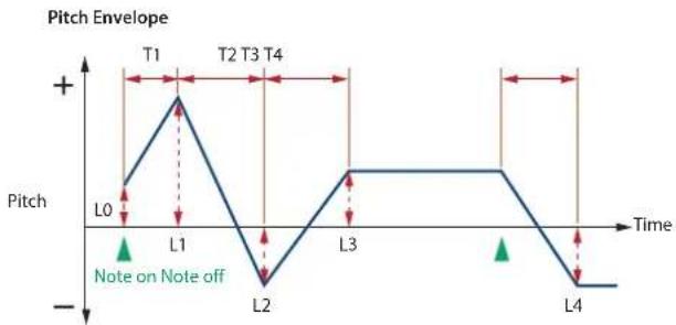
line
| Time | Pitch | |------|-------| | L0 | | | L1 | | | L2 | | | L3 | | | L4 | |RHYTHM KEY TVF
A filter cuts or boosts a specific frequency region to change a sound's brightness, thickness, or other qualities.

Parameter Range/Explanation
| TYPE | Type of filterOFF: No filter is used.LPF: Low Pass Filter. This reduces the volume of all frequencies above the cutoff frequency in order to round off, or un-brighten the sound.BPF: Band Pass Filter. This leaves only the frequencies in the region of the cutoff frequency, and cuts the rest. This can be useful when creating distinctive sounds.HPF: High Pass Filter. This cuts the frequencies in the region below the cutoff frequency. This is suitable for creating percussive sounds emphasizing their higher tones.PKG: Peaking Filter. This emphasizes the frequencies in the region of the cutoff frequency. You can use this to create wah-wah effects by employing an LFO to change the cutoff frequency cyclically.LPF2: Low Pass Filter 2. Although frequency components above the cutoff frequency are cut, the sensitivity of this filter is half that of the LPF. This filter is good for use with simulated instrument sounds such as the acoustic piano.LPF3: Low Pass Filter 3. Although frequency components above the cutoff frequency are cut, the sensitivity of this filter changes according to the cutoff frequency. While this filter is also good for use with simulated acoustic instrument sounds, the nuance it exhibits differs from that of the LPF2, even with the same TVF Envelope settings.* If you set "LPF2" or "LPF3," the setting for the RES parameter will be ignored. |
| CUTOFF(Cutoff Frequency) | 0–127Frequency at which the filter begins to have an effect on the waveform's frequency components |
| RES(Resonance) | 0–127Emphasizes the portion of the sound in the region of the cutoff frequency, adding character to the sound.* Excessively high settings can produce oscillation, causing the sound to distort. |
Parameter Range/Explanation
| RES VEL SENS(Resonance Velocity Sens) | -63–+63This allows keyboard velocity to modify the amount of Resonance.If you want strongly played notes to have a greater Resonance effect, set this parameter to positive (+) settings. |
Resonance
PKGHPFBPFLPF

line
| Parameter Value | Frequency Level 1 | Frequency Level 2 | Frequency Level 3 | Frequency Level 4 | Frequency Level 5 | Cutoff Frequency | |-----------------|-------------------|-------------------|-------------------|-------------------|-------------------|------------------| | Low | Low | Low | Low | Low | Low | Low | | Medium | Medium | Medium | Medium | Medium | Medium | Medium | | High | High | High | High | High | High | High |Parameter Range/Explanation
| VEL CURVE(Cutoff Velocity Curve) | FIX, 1-7Curve that determines how keyboard playing dynamics (velocity) will affect the cutoff frequencySet this to “FIX” if you don't want the cutoff frequency to be affected by the keyboard velocity. |
| FIX 1 2 34 5 6 7 | |
| VEL SENS(Cutoff Velocity Sens) | -63-+63Use this parameter when changing the cutoff frequency to be applied as a result of changes in playing velocity.If you want strongly played notes to raise the cutoff frequency, set this parameter to positive (+) settings. |
FILTER ENV (TVF ENVELOPE)
| Parameter Range/Explanation | |
| DEPTH | -63--+63Depth of the TVF envelopeHigher settings will cause the TVF envelope to produce greater change. Negative (-) settings will invert the shape of the envelope. |
| VEL CURVE(Velocity Curve) | FIX, 1-7Curve that determines how keyboard playing dynamics (velocity) will affect the TVF envelopeSet this to "FIX" if you don't want the TVF Envelopeto be affected by the keyboard velocity. |
| VEL SENS(Velocity Sens) | -63--+63Specifies how keyboard playing dynamics will affect the depth of the TVF envelope.Positive (+) settings will cause the TVF envelope to have a greater effect for strongly played notes, and negative (-) settings will cause the effect to be less. |
| T1 SENS | -63-+63This allows keyboard dynamics to affect the T1 of the TVF envelope.If you want T1 to be speeded up for strongly played notes, set this parameter to a positive (+) value. |
| T4 SENS | -63-+63Use this parameter when you want key release speed to affect the T4 value of the TVF envelope.If you want T4 to be speeded up for quickly released notes, set this parameter to a positive (+) value. |
| T1-4(Time 1-4) | 0-127TVF envelope times (T1-T4)Higher settings will lengthen the time until the next cutoff frequency level is reached. |
| L0-4(Level 0-4) | 0-127TVF envelope levels (L0-L4)Specify how the cutoff frequency will change at each point, relative to the Cutoff Frequency value. |

line
| Time | Cutoff frequency | |------|------------------| | L0 | 0 | | L1 | Peak (T1) | | L2 | Low | | L3 | Low | | L4 | High (L2) | | End | Low |TVA + VELOCITY
RHYTHM KEY TVA
This adjusts the volume.
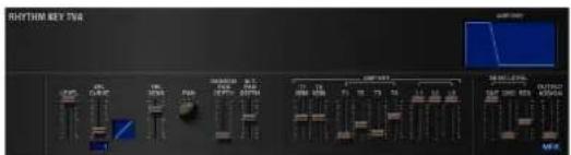
| Parameter Range/Explanation | |
| LEVEL | 0-127Volume of the rhythm keyThis setting is useful primarily for adjusting the volume balance between rhythm ones. |
| VEL CURVE(Velocity Curve) | FIX, 1-7Curve that determines how keyboard playing dynamics (velocity) will affect the volume of the rhythm keySet this to “FIX” if you don't want the volume of the tone to be affected by the keyboard velocity. |
| VEL SENS(Velocity Sens) | -63-+63Set this when you want the volume of the rhythm key to change depending on keyboard playing dynamics.Set this to a positive (+) value to have the changes in tone volume increase the more forcefully the keys are played; to make the tone play more softly as you play harder, set this to a negative (-) value. |
| Parameter Range/Explanation | |
| PAN | L64-0-63RLeft/right position of the rhythm key |
| RANDOM PAN DEPTH | 0-63Use this parameter when you want the stereo location to change randomly each time you press a key.Higher settings will produce a greater amount of change. |
| ALT. PAN DEPTH(Alternate Pan Depth) | L63-0-63RThis setting causes panning to be alternated between left and right each time a key is pressed.Higher settings will produce a greater amount of change. “L” or “R” settings will reverse the order in which the pan will alternate between left and right. For example if two rhythm keys are set to “L” and “R” respectively, the panning of the two rhythm keys will alternate each time they are played. |
AMP ENV (TVA ENVELOPE)
| Parameter Range/Explanation | |
| T1 SENS | -63-+63This allows keyboard dynamics to affect the T1 of the TVA envelope.If you want Time 1 to be speeded up for strongly played notes, set this parameter to a positive (+) value. If you want it to be slowed down, set this to a negative (-) value. |
| T4 SENS | -63-+63Use this parameter when you want key release speed to affect the T4 value of the TVA envelope.If you want T4 to be speeded up for quickly released notes, set this parameter to a positive (+) value. If you want it to be slowed down, set this to a negative (-) value. |
| T1-4(Time 1-4) | 0-127TVA envelope times (T1-T4)Higher settings will lengthen the time until the next volume level is reached. |
| L1-3(Level 1-3) | 0-127TVA envelope levels (L1-L3)Specify how the volume will change at each point, relative to the LEVEL value. |

line
| Time | Level | |------|-------| | T1 | + | | T2 | + | | T3 | + | | T4 | + | | L1 | Peak | | L2 | Low | | L3 | Low | | Note on | - | | Note off | - |OUTPUT
| Parameter Range/Explanation | |
| SEND LEVEL OUT (Output Level) | 0-127Level of the signal that is sent to the output destination specified by OUTPUT ASSIGN |
| SEND LEVEL (OUTPUT ASSIGN = MFX) | |
| CHO(Chorus Send) | 0-127Level of the signal sent to chorus for each rhythm key if the rhythm key is sent through MFX |
| REV(Reverb Send) | 0-127Level of the signal sent to reverb for each rhythm key if the rhythm key is sent through MFX |
| SEND LEVEL (OUTPUT ASSIGN = non MFX) | |
| CHO(Chorus Send) | 0-127Level of the signal sent to chorus for each rhythm key if the rhythm key is not sent through MFX |
Parameter Range/Explanation
| REV(Reverb Send) | 0–127Level of the signal sent to reverb for each rhythm key if the rhythm key is not sent through MFX |
| OUTPUT ASSIGN | Specifies how the direct sound of each rhythm key will be output.MFX: Output in stereo through multi-effects. You can also apply chorus or reverb to the sound that passes through multi-effects.L+R: Output in stereo to the OUTPUT without passing through the multi-effectL: Output in mono to the OUTPUT L without passing through the multi-effectR: Output in mono to the OUTPUT R without passing through the multi-effect* If the OUTPUT ASSIGN in “RHYTHM COMMON” is set to anything other than “TONE,” these settings will be ignored.* Sounds are output to chorus and reverb in mono at all times.* The output destination of the signal after passing through the chorus is set with the CHORUS OUTPUT SELECT parameters (p. 34). |
RHYTHM KEY VELOCITY RANGE
You can use the force with which keys are played to control the way each waveform is played.

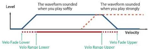
Parameter Range/Explanation
| VELOCITY CONTROL | OFF, ON, RANDOMDetermines whether a different waveform is played (ON) or not (OFF) depending on the force with which the key is played (velocity).RANDOM:The rhythm key's constituent waveforms will sound randomly, regardless of any Velocity messages. |
| FADE LOWER | 0–127Determines what will happen to the waveform's level when the rhythm key is played at a velocity lower than Velocity Range Lower.If you don't want the waveform to sound at all, set this parameter to "0." |
| LOWER | 1-(UPPER)Specifies the lowest velocity at which the waveform will sound. |
| UPPER | (LOWER)-127Specifies the highest velocity at which the waveform will sound. |
| FADE UPPER | 0–127Determines what will happen to the waveform's level when the rhythm key is played at a velocity greater than Velocity Range Upper.If you don't want the waveform to sound at all, set this parameter to "0." |
Applying Effects
You can apply multi-effects (MFX), chorus, and reverb to each patch or rhythm set; the same effect will be applied to each tone.
By adjusting the amount of signal that is sent from each tone to each effect, you can control the depth of the effect for each tone.
Effect Settings
When you click the following buttons in the Navigation block, the content shown in the Main block will change, allowing you to edit the effect settings.
Signal Flow and Parameters (ROUTING)
Here you can make overall settings for effects, such as the output destination and level of the various signals.
PATCH EFFECTS ROUTING screen
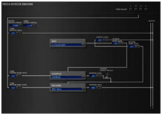
flowchart
graph TD
    A["INPUT"] --> B["RFX"]
    B --> C["OUTPUT LEVEL"]
    C --> D["OUTPUT LEVEL"]
    D --> E["OUTPUT LEVEL"]
    E --> F["OUTPUT LEVEL"]
    F --> G["OUTPUT LEVEL"]
    G --> H["OUTPUT LEVEL"]
    H --> I["OUTPUT LEVEL"]
    I --> J["OUTPUT LEVEL"]
    J --> K["OUTPUT LEVEL"]
    K --> L["OUTPUT LEVEL"]
    L --> M["OUTPUT LEVEL"]
    M --> N["OUTPUT LEVEL"]
    N --> O["OUTPUT LEVEL"]
    O --> P["OUTPUT LEVEL"]
    P --> Q["OUTPUT LEVEL"]
    Q --> R["OUTPUT LEVEL"]
    R --> S["OUTPUT LEVEL"]
    S --> T["OUTPUT LEVEL"]
    T --> U["OUTPUT LEVEL"]
    U --> V["OUTPUT LEVEL"]
    V --> W["OUTPUT LEVEL"]
    W --> X["OUTPUT LEVEL"]
    X --> Y["OUTPUT LEVEL"]
    Y --> Z["OUTPUT LEVEL"]
    Z --> AA["OUTPUT LEVEL"]
    AA --> AB["OUTPUT LEVEL"]
    AB --> AC["OUTPUT LEVEL"]
    AC --> AD["OUTPUT LEVEL"]
    AD --> AE["OUTPUT LEVEL"]
    AE --> AF["OUTPUT LEVEL"]
    AF --> AG["OUTPUT LEVEL"]
    AG --> AH["OUTPUT LEVEL"]
    AH --> AI["OUTPUT LEVEL"]
    AI --> AJ["OUTPUT LEVEL"]
    AJ --> AK["OUTPUT LEVEL"]
    AK --> AL["OUTPUT LEVEL"]
    AL --> AM["OUTPUT LEVEL"]
    AM --> AN["OUTPUT LEVEL"]
    AN --> AO["OUTPUT LEVEL"]
    AO --> AP["OUTPUT LEVEL"]
    AP --> AQ["OUTPUT LEVEL"]
    AQ --> AR["OUTPUT LEVEL"]
    AR --> AS["OUTPUT LEVEL"]
    AS --> AT["OUTPUT LEVEL"]
    AT --> AU["OUTPUT LEVEL"]
    AU --> AV["OUTPUT LEVEL"]
    AV --> AW["OUTPUT LEVEL"]
    AW --> AX["OUTPUT LEVEL"]
    AX --> AY["OUTPUT LEVEL"]
    AY --> AZ["OUTPUT LEVEL"]
    AZ --> BA["OUTPUT LEVEL"]
    BA --> BB["OUTPUT LEVEL"]
    BB --> BC["OUTPUT LEVEL"]
    BC --> BD["OUTPUT LEVEL"]
    BD --> BE["OUTPUT LEVEL"]
    BE --> BF["OUTPUT LEVEL"]
    BF --> BG["OUTPUT LEVEL"]
    BG --> BH["OUTPUT LEVEL"]
    BH --> BI["OUTPUT LEVEL"]
    BI --> BJ["OUTPUT LEVEL"]
    BJ --> BK["OUTPUT LEVEL"]
    BK --> BL["OUTPUT LEVEL"]
    BL --> BM["OUTPUT LEVEL"]
    BM --> BN["OUTPUT LEVEL"]
    BN --> BO["OUTPUT LEVEL"]
    BO --> BP["OUTPUT LEVEL"]
    BP --> BQ["OUTPUT LEVEL"]
    BQ --> BR["OUTPUT LEVEL"]
    BR --> BS["OUTPUT LEVEL"]
    BS --> BT["OUTPUT LEVEL"]
    BT --> BU["OUTPUT LEVEL"]
    BU --> BV["OUTPUT LEVEL"]
    BV --> BW["OUTPUT LEVEL"]
    BW --> BX["OUTPUT LEVEL"]
    BX --> BY["OUTPUT LEVEL"]
    BY --> BZ["OUTPUT LEVEL"]
RHYTHM EFFECTS ROUTING screen

flowchart
graph TD
    A["TIME ON/OFF"] --> B["TIME ON/OFF"]
    B --> C["ON/OFF"]
    C --> D["CHOPS"]
    D --> E["FROUING"]
    E --> F["ON/OFF"]
    F --> G["CHOPS"]
    G --> H["OUTPUT"]
Parameter Range/Explanation
| TONE SELECT / KEY NAME | 1-4 (A0-C8)The tone (rhythm key) to editIf you've selected a rhythm set, this will be KEY NAME.* You can select multiple tones by clicking a TONE SELECT button while holding down the computer's Shift key.* You can select all tones by holding down the computer's Command (Ctrl) key and clicking a TONE SELECT button. |
| Parameter Range/Explanation | |
| PATCH OUTPUT ASSIGN / RHYTHM OUTPUT ASSIGN | Specifies how the unprocessed sound of the patch (rhythm set) will be outputIf you've selected a rhythm set, this will be RHYTHM OUTPUT ASSIGN.MFX: Output in stereo via the multi-effect. Chorus and reverb can also be applied after the multi-effect.L+R: Output in stereo from the OUTPUT without passing through the multi-effectL: Output in mono from the OUTPUT L without passing through the multi-effectR: Output in mono from the OUTPUT R without passing through the multi-effectTONE: Output according to the settings of each tone |
| TONE OUTPUT ASSIGN | Specifies how the unprocessed sound of each tone will be outputMFX: Output in stereo via the multi-effect. Chorus and reverb can also be applied after the multi-effect.L+R: Output in stereo from the OUTPUT without passing through the multi-effectL: Output in mono from the OUTPUT L without passing through the multi-effectR: Output in mono from the OUTPUT R without passing through the multi-effect* The setting you specify here is valid only if PATCH OUTPUT ASSIGN is set to “TONE.”* If STRUCTURE (p. 15) is set to TYPE 02–10, the settings for tone 1 (3) will follow the settings of tone 2 (4). (This is because the outputs of tones 1 and 2 are combined into tone 2, and the outputs of tones 3 and 4 are combined into tone 4.) |
| TONE OUTPUT LEVEL | 0–127Level of signal sent from each tone to the destination specified by OUTPUT ASSIGN |
| TONE CHORUS SEND LEVEL | 0–127Level of signal sent from each tone to the chorus |
| TONE REVERB SEND LEVEL | 0–127Level of signal sent from each tone to the reverb |
| MFX | 0–78Type of multi-effect to use (choose one of 78 types) For details on each multi-effect, refer to “Multi-Effects Parameters (MFX)” (p. 37). |
| MFX OUTPUT LEVEL | 0–127Volume of the sound that has been processed by the multi-effect |
| MFX CHORUS SEND LEVEL | 0–127Amount of chorus applied to the sound that has been processed by the multi-effect |
| MFX REVERB SEND LEVEL | 0–127Amount of reverb applied to the sound that has been processed by the multi-effect |
| CHORUS | Type of chorusOFF: Chorus/delay will not be usedCHORUS: ChorusDELAY: DelayGM2 CHORUS: GM2 chorus |
| CHORUS LEVEL | 0–127Volume of the sound that has been processed by the chorus |
| CHORUS OUTPUT SELECT | Output destination of the sound that has been processed by the chorusMAIN: Output in stereo to the OUTPUTMAIN+REV: Output in stereo to the OUTPUT and in mono to the reverbREV: Output in mono to reverb |
| REVERB | Type of reverbOFF: Reverb will not be usedREVERB: Basic reverbSRV ROOM: Reverb that simulates the reverberation of a room in greater detailSRV HALL: Reverb that simulates the reverberation of a hall in greater detailSRV PLATE: Simulation of a plate echo (a reverb device that uses a metal plate)GM2 REVERB: GM2 reverb |
| REVERB LEVEL | 0–127Volume of the sound that has been processed by the reverb |
Multi-Effect Settings (MFX)

| Parameter Range/Explanation | ||
| ON/OFF | OFF, ONTurns the multi-effect on/off | |
| TYPE | 00: THROUGH-78: SYMPATHETIC RESONANCESelects the type of multi-effect.Choose "00: THROUGH" if you don't want to apply a multi-effect. | |
| SEND LEVEL | OUT | 0-127Volume of the sound that has been processed by the multi-effect |
| CHO | 0-127Amount of chorus applied to the sound that has been processed by the multi-effect | |
| REV | 0-127Amount of reverb applied to the sound that has been processed by the multi-effect | |
| Parameters of each MFX type | Edit the parameters of the MFX type you've selected. Refer to "Multi-Effects Parameters (MFX)" (p. 37). | |
Controlling a Multi-Effect via MIDI
(CONTROL SOURCE/DESTINATION/SENS)
Multi-Effect Control
The SRX ORCHESTRA allows you to use control changes and other common MIDI messages to control the most important multi-effect parameters.
For example, you might use the pitch bend lever to control the degree of distortion, or use keyboard touch to change the delay time. The parameters that can be controlled in this way are predetermined for each type of multi-effect; such parameters are indicated by a “#” in the parameter lists in “Multi-Effects Parameters (MFX)” (p. 37).
"Multi-effect control" is the capability of using MIDI messages in this way to control multi-effect parameters in real time. You can specify up to four multi-effect control assignments for the MFX.
In order to use multi-effect control, you'll need to specify which MIDI message (SOURCE) will control which parameter (DESTINATION) by what amount (SENS).
- As a substitute for multi-effect control, you can also use "MATRIX CONTROL" (p. 26) to control important multi-effect parameters in real time.
| Parameter Range/Explanation | |
| CONTROL SOURCE(1-4) | Specifies the MIDI message that will control the corresponding MFX control parameter.OFF: MFX Control will not be used.CC01-31: Controller number 1-31CC33-95: Controller number 33-95PITCH BEND: Pitch bendAFTERTOUCH: Aftertouch |
| DESTINATION(1-4) | Selects the multi-effect parameter that will be controlled by CONTROL SOURCE.The type of parameters that can be selected will depend on the type of multi-effect you've selected in MFX Type.Refer to "Multi-Effects Parameters (MFX)" (p. 37). |
| SENS(1-4) | -63-+63Specifies the depth of multi-effect control.Specify a positive (+) value if you want to change the value of the assigned destination in a positive direction (larger, toward the right, faster, etc.), or specify a negative value (-) if you want to change the value in a negative direction (smaller, toward the left, slower, etc.).Larger values will allow a greater amount of control. |
A patch or rhythm set contains parameters that specify whether pitch bend, controller number 11 (expression), and controller number 64 (hold 1) will be received for each tone or rhythm key (p. 26, p. 29). If these settings are "ON," receiving that MIDI message will not only change the setting of the assigned destination parameter, but will also apply the corresponding pitch bend, expression, or hold 1 effect. Leave them "OFF" if you only want to control the multi-effect parameter.
Chorus and Reverb Settings

Chorus Settings
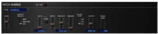
Parameter Range/Explanation
| ON/OFF | Turns the chorus on/off |
| TYPE | Type of chorusOFF: Chorus/delay will not be usedCHORUS: ChorusDELAY: DelayGM2 CHORUS: GM2 chorus |
| LEVEL | Volume of the sound that has been processed by the chorus |
| OUTPUT SELECT | Output destination of the sound that has been processed by the chorusMAIN: Output in stereo to the OUTPUTMAIN+REV: Output in stereo to the OUTPUT and in mono to the reverbREV: Output in mono to reverb |
| Parameters for each chorus type | Set the parameters of the selected chorus type.Refer to “Chorus Parameters” (p. 69). |
Reverb Settings

Parameter Range/Explanation
| ON/OFF | Turns the reverb on/off* The reverb on/off setting cannot be saved. |
| TYPE | Type of reverbOFF:Reverb will not be usedREVERB:Basic reverb/delaySRV ROOM:Reverb that simulates the reverberation of a roomSRV HALL:Reverb that simulates the reverberation of a hallSRV PLATE:Simulation of a plate echo (a reverb device that uses a metal plate)GM2 REVERB:GM2 reverb |
| LEVEL | Volume of the sound that has been processed by the reverb |
| Parameters for each reverb type | Set the parameters of the selected reverb type.Refer to"Reverb Parameters"(p. 69). |
Multi-Effects Parameters (MFX)
The multi-effects feature 78 different kinds of effects. Some of the effects consist of two or more different effects connected in series.
Parameters marked with a sharp “#” can be controlled using a Multi-Effects Control (p. 35) or Matrix Control (p. 26). (Two setting items will change simultaneously for “#1” and “#2.”)
FILTER (10 types)
| 01 | EQUALIZER p. 39 |
| 02 | SPECTRUM p. 39 |
| 03 | ISOLATOR p. 39 |
| 04 | LOW BOOST p. 39 |
| 05 | SUPER FILTER p. 40 |
| 06 | STEP FILTER p. 40 |
| 07 | ENHANCER p. 40 |
| 08 | AUTO WAH p. 41 |
| 09 | HUMANIZER p. 41 |
| 10 | SPEAKER SIMULATOR p. 42 |
MODULATION (12 types)
| 11 | PHASER p. 42 | |
| 12 | STEP PHASER p. 43 | |
| 13 | MULTI STAGE PHASER p. 43 | |
| 14 | INFINITE PHASER | p. 43 |
| 15 | RING MODULATOR | p. 44 |
| 16 | STEP RING MODULATOR | p. 44 |
| 17 | TREMOLO p. 44 | |
| 18 | AUTO PAN | p. 45 |
| 19 | STEP PAN | p. 45 |
| 20 | SLICER | p. 45 |
| 21 | ROTARY | p. 46 |
| 22 | VK ROTARY | p. 46 |
CHORUS (12 types)
| 23 | CHORUS | p. 47 |
| 24 | FLANGER | p. 47 |
| 25 | STEP FLANGER | p. 48 |
| 26 | HEXA-CHORUS | p. 48 |
| 27 | TREMOLO CHORUS | p. 48 |
| 28 | SPACE-D | p. 49 |
| 29 | 3D CHORUS | p. 49 |
| 30 | 3D FLANGER | p. 50 |
| 31 | 3D STEP FLANGER | p. 50 |
| 32 | 2BAND CHORUS | p. 51 |
| 33 | 2BAND FLANGER | p. 51 |
| 34 | 2BAND STEP FLANGER | p. 52 |
DYNAMICS (8 types)
| 35 | OVERDRIVE p. 52 | |
| 36 | DISTORTION p. 52 | |
| 37 | VS OVERDRIVE | p. 52 |
| 38 | VS DISTORTION | p. 53 |
| 39 | GUITAR AMP SIMULATOR | p. 53 |
| 40 | COMPRESSOR | p. 53 |
| 41 | LIMITER p. 54 | |
| 42 | GATE | p. 54 |
DELAY (13 types)
| 43 | DELAY | p.54 |
| 44 | LONG DELAY | p.55 |
| 45 | SERIAL DELAY | p.55 |
| 46 | MODULATION DELAY p. 56 | |
| 47 | 3TAP PAN DELAY | p. 56 |
| 48 | 4TAP PAN DELAY | p. 57 |
| 49 | MULTI TAP DELAY | p. 57 |
| 50 | REVERSE DELAY | p. 58 |
| 51 | SHUFFLE DELAY | p. 58 |
| 52 | 3D DELAY | p. 59 |
| 53 | TIME CTRL DELAY | p. 59 |
| 54 | LONG TIME CTRL DELAY | p. 60 |
| 55 | TAPE ECHO p. 60 | |
LO-FI (5 types)
| 56 | LOFI NOISE | p. 61 |
| 57 | LOFI COMPRESS | p. 61 |
| 58 | LOFI RADIO | p. 62 |
| 59 | TELEPHONE | p. 62 |
| 60 | PHONOGRAPH | p. 62 |
PITCH (3 types)
| 61 | PITCH SHIFTER | p. 63 |
| 62 | 2VOICE PITCH SHIFTER | p. 63 |
| 63 | STEP PITCH SHIFTER | p. 64 |
REVERB(2 types)
| 64 | REVERB | p. 64 |
| 65 | GATED REVERB | p. 65 |
COMBINATION(12 types)
| 66 | OVERDRIVE → CHORUS | p. 65 |
| 67 | OVERDRIVE → FLANGER | p. 65 |
| 68 | OVERDRIVE → DELAY | p. 65 |
| 69 | DISTORTION → CHORUS | p. 66 |
| 70 | DISTORTION → FLANGER | p. 66 |
| 71 | DISTORTION → DELAY | p. 66 |
| 72 | ENHANCER → CHORUS | p. 66 |
| 73 | ENHANCER → FLANGER | p. 66 |
| 74 | ENHANCER → DELAY | p. 67 |
| 75 | CHORUS → DELAY | p. 67 |
| 76 | FLANGER → DELAY | p. 67 |
| 77 | CHORUS → FLANGER | p. 68 |
PIANO (1 type)
| 78 | SYMPATHETIC RESONANCE | p. 68 |
About RATE and DELAY TIME
Some of the effect parameters can be set in terms of a note value (these are parameters that specify a cycle, such as RATE or DELAY TIME). These parameters have a SYNC switch that lets you choose whether to set them as a numerical frequency or time, or as a note value.
If you want to set RATE (DELAY TIME) as a numerical value, set the SYNC switch to "OFF." If you want to set it as a note value, set the SYNC switch to "ON."
* If RATE is specified as a note value, the modulation is synchronized to the tempo of the DAW.
| Sixty-fourth-note triplet | Sixty-fourthnote | Thirty-second-note triplet | Thirty-secondnote | ||||
| Sixteenth-note triplet | Dotted thirty-second note | Sixteenth note | Eighth-note triplet | ||||
| Dotted sixteenth note | Eighth note | Quarter-note triplet | Dotted eighth note | ||||
| Quarter note | Half-note triplet | Dotted quarter note | Half note | ||||
| o3 | Whole-note triplet | Dotted half note | Whole note | Double-note triplet | |||
| Dotted whole note | Double note | ||||||
NOTE
- If a parameter whose SYNC switch is set to "ON" is specified as a destination for multi-effect control, you will not be able to use multi-effect control to control that parameter.
- If you specify the delay time as a note value, slowing down the tempo will not change the delay time beyond a certain length. This is because there is an upper limit for the delay time; if the delay time is specified as a note value and you slow down the tempo until this upper limit is reached, the delay time cannot change any further. This upper limit is the maximum value that can be specified when setting the delay time as a numerical value.
When Using 3D Effects
The following 3D effects utilize RSS (Roland Sound Space) technology to create a spaciousness that cannot be produced by delay, reverb, chorus, etc.
52: 3D DELAY
29: 3D CHORUS
30: 3D FLANGER
31: 3D STEP FLANGER
When using these effects, we recommend that you place the speakers as follows. Also, make sure that the speakers are at a sufficient distance from the walls on either side.

If the left and right speakers are too far apart, or if there is too much reverberation, the full 3D effect may not appear.
Each of these effects has an "OUTPUT MODE" parameter. If the sound from the OUTPUT is to be heard through speakers, set this parameter to "SPEAKER." If the sound is to be heard through headphones, set it to "PHONES." This will ensure that the optimal 3D effect will be heard. If this parameter is not set correctly, the full 3D effect may not appear.
About the STEP RESET function
06: STEP FILTER
16: STEP RING MODULATOR
19: STEP PAN
20: SLICER
63: STEP PITCH SHIFTER
The above five types contain a sixteen-step sequencer.
For these types, you can use a multi-effect control (p. 35) to reset the sequence to play from the first step.
To do this, set the multi-effect control DESTINATION to "STEP RESET."
For example if you are using the modulation lever to control the effect, you would make the following settings.
SOURCE: CC01: MODULATION
DESTINATION: STEP RESET
SENS: 63
With these settings, the sequence will play back from the first step whenever you operate the modulation lever.
01: EQUALIZER
this is a four-band stereo equalizer (low, mid x 2, high).

flowchart
graph LR
    A["L in"] --> B["4-Band EQ"] --> C["L out"]
    D["R in"] --> E["4-Band EQ"] --> F["R out"]
Parameter Value Explanation
| LOW FREQ | 200, 400 Hz Frequency of the low range | |
| LOW GAIN # | -15–+15 dB | Amount of boost/cut for the low-frequency range |
| MID1 FREQ | 200–8000 Hz Frequency of the middle range 1 | |
| MID1 Q | 0.5, 1.0, 2.0, 4.0, 8.0 | Width of the middle range 1Set a higher value for Q to narrow the range to be affected. |
| MID1 GAIN | -15–+15 dB Gain of the middle range 1 | |
| MID2 FREQ | 200–8000 Hz Frequency of the middle range 2 | |
| MID2 Q | 0.5, 1.0, 2.0, 4.0, 8.0 | Width of the middle range 2Set a higher value for Q to narrow the range to be affected. |
| MID2 GAIN | -15–+15 dB Gain of the middle range 2 | |
| HIGH FREQ | 2000, 4000, 8000 Hz Frequency of the high range | |
| HIGH GAIN # | -15–+15 dB | Amount of boost/cut for the high-frequency range |
| OUTPUT LEVEL # | 0–127 Output Level | |
02: SPECTRUM
This is a stereo spectrum. Spectrum is a type of filter which modifies the timbre by boosting or cutting the level at specific frequencies.

flowchart
graph LR
    A["L in"] --> B["Spectrum"] --> C["L out"]
    D["R in"] --> E["Spectrum"] --> F["R out"]
Parameter Value Explanation
| 250Hz | -15–+15 dB Gain of each frequency band | |
| 500Hz | ||
| 1000Hz | ||
| 1250Hz | ||
| 2000Hz | ||
| 3150Hz | ||
| 4000Hz | ||
| 8000Hz | ||
| BAND WIDTH | 0.5, 1.0, 2.0, 4.0, 8.0 | Simultaneously adjusts the width of the adjusted ranges for all the frequency bands. |
| OUTPUT LEVEL # | 0–127 Output Level | |
03: ISOLATOR
This is an equalizer which cuts the volume greatly, allowing you to add a special effect to the sound by cutting the volume in varying ranges.

flowchart
graph LR
    A["L in"] --> B["Isolator"]
    B --> C["Low Boost"]
    C --> D["L out"]
    E["R in"] --> F["Isolator"]
    F --> G["Low Boost"]
    G --> H["R out"]
Parameter Value Explanation
| BOOST/CUT LOW # | -60-+4 dB | These boost and cut each of the High, Middle, and Low frequency ranges.At -60 dB, the sound becomes Inaudible. 0 dB is equivalent to the Input level of the sound. |
| BOOST/CUT MID # | ||
| BOOST/CUT HIGH # | ||
| ANTI PHASE LOW SW | OFF, ON | Turns the Anti-Phase function on and off for the Low frequency ranges.When turned on, the counter-channel of stereo sound is inverted and added to the signal. |
| ANTI PHASE LOW LEVEL | 0-127 | Adjusts the Anti-Phase Level settings for the Low frequency ranges.Adjusting this level for certain frequencies allows you to lend emphasis to specific parts. (This is effective only for stereo source.) |
| ANTI PHASE MID SW | OFF, ON Settings of the Anti-Phase functionfor the Middle frequency ranges | |
| ANTI PHASE MID LEVEL | 0-127 | The parameters are the same as for the Low frequency ranges. |
| LOW BOOST SW | OFF, ON | Turns Low Booster on/off.This emphasizes the bottom to create a heavy bass sound. |
| LOW BOOST LEVEL | 0-127 | Increasing this value gives you a heavier low end.* Depending on the Isolator and filter settings this effect may be hard to distinguish. |
| OUTPUT LEVEL | 0-127 Output Level | |
04: LOW BOOST
Boosts the volume of the lower range, creating powerful lows.

flowchart
graph LR
    A["L in"] --> B["Low Boost"]
    B --> C["2-Band EQ"]
    C --> D["L out"]
    E["R in"] --> F["Low Boost"]
    F --> G["2-Band EQ"]
    G --> H["R out"]
Parameter Value Explanation
| BOOST FREQUENCY # | 50–125 Hz | Center frequency at which the lower range will be boosted |
| BOOST GAIN # | 0–+12 dB | Amount by which the lower range will be boosted |
| BOOST WIDTH | WIDE, MID, NARROW | Width of the lower range that will be boosted |
| EQ GAIN LOW | -15–+15 dB Gain of the low frequency range | |
| EQ GAIN HIGH | -15–+15 dB Gain of the high frequency range | |
| OUTPUT LEVEL | 0–127 Output level | |
05: SUPER FILTER
This is a filter with an extremely sharp slope. The cutoff frequency can be varied cyclically.

flowchart
graph LR
    A["L in"] --> B["Super Filter"] --> C["L out"]
    D["R in"] --> E["Super Filter"] --> F["R out"]
Parameter Value Explanation
| FILTER TYPE | LPF, BPF, HPF, NOTCH | Filter typeFrequency range that will pass through each filterLPF: frequencies below the cutoffBPF: frequencies in the region of the cutoffHPF: frequencies above the cutoffNOTCH: frequencies other than the region of the cutoff |
| FILTER SLOPE | -12, -24, -36 dB | Amount of attenuation per octave-36 dB: extremely steep-24 dB: steep-12 dB: gentle |
| FILTER CUTOFF # | 0–127 | Cutoff frequency of the filterIncreasing this value will raise the cutoff frequency. |
| FILTER RESONANCE # | 0–127 | Filter resonance levelIncreasing this value will emphasize the region near the cutoff frequency. |
| FILTER GAIN | 0–+12 dB Amount of boost for the filter output | |
| MODULATION SW | OFF, ON | Turns on/off cyclic change of the cutoff frequency |
| MODULATION WAVE | TRI, SQR, SIN, SAW1, SAW2 | How the cutoff frequency will be modulatedTRI: triangle waveSQR: square waveSIN: sine waveSAW1: sawtooth wave (upward)SAW2: sawtooth wave (downward) |
SAW1SAW2 | ||
| RATE # | 0.05–10.00 Hz, note Rate of modulation | |
| DEPTH | 0–127 Depth of modulation | |
| ATTACK # | 0–127 | Speed at which the cutoff frequency will changeThis is effective if Modulation Wave is SQR, SAW1, or SAW2. |
| OUTPUT LEVEL | 0–127 Output Level | |
06: STEP FILTER
This is a filter whose cutoff frequency can be modulated in steps. You can specify the pattern by which the cutoff frequency will change.

flowchart
graph LR
    A["L in"] --> B["Step Filter"]
    C["R in"] --> D["Step Filter"]
    B --> E["L out"]
    D --> F["R out"]
Parameter Value Explanation
| RATE # | 0.05-10.00 Hz, note Rate of modulation | |
| ATTACK # | 0-127 | Speed at which the cutoff frequency changes between steps |
| FILTER TYPE | LPF, BPF, HPF, NOTCH | Filter typeFrequency range that will pass through each filterLPF: frequencies below the cutoffBPF: frequencies in the region of the cutoffHPF: frequencies above the cutoffNOTCH: frequencies other than the region of the cutoff |
| FILTER SLOPE | -12, -24, -36 dB | Amount of attenuation per octave-12 dB: gentle-24 dB: steep-36 dB: extremely steep |
| FILTER RESONANCE # | 0-127 | Filter resonance levelIncreasing this value will emphasize the region near the cutoff frequency. |
| FILTER GAIN | 0-12 dB Amount of boost for the filter output | |
| OUTPUT LEVEL | 0-127- Output level | |
| STEP 1-16 | 0-127 Cutoff frequency at each step | |
MEMO
You can use multi-effect control to make the step sequence play again from the beginning (p. 38).
07: ENHANCER
Controls the overtone structure of the high frequencies, adding sparkle and tightness to the sound.

flowchart
graph LR
    A["L in"] --> B["Enhancer"]
    B --> C["Mix"]
    C --> D["+"]
    D --> E["2-Band EQ"]
    E --> F["L out"]
    G["R in"] --> H["Enhancer"]
    H --> I["Mix"]
    I --> J["+"]
    J --> K["2-Band EQ"]
    K --> L["R out"]
Parameter Value Explanation
| SENS # | 0-127 Sensitivity of the enhancer | |
| MIX # | 0-127 | Level of the overtones generated by the enhancer |
| EQ GAIN LOW | -15-+15 dB | Amount of boost/cut for the low-frequency range |
| EQ GAIN HIGH | -15-+15 dB | Amount of boost/cut for the high-frequency range |
| OUTPUT LEVEL | 0-127 Output Level | |
08: AUTO WAH
Cyclically controls a filter to create cyclic change in timbre.

flowchart
graph LR
    A["L in"] --> B["Auto Wah"]
    B --> C["2-Band EQ"]
    C --> D["L out"]
    E["R in"] --> F["Auto Wah"]
    F --> G["2-Band EQ"]
    G --> H["R out"]
Parameter Value Explanation
| FILTER TYPE | LPF, BPF | Type of filterLPF: The wah effect will be applied over a wide frequency range.BPF: The wah effect will be applied over a narrow frequency range. |
| SENS # | 0-127 | Adjusts the sensitivity with which the filter is controlled. |
| MANUAL # | 0-127 | Adjusts the center frequency at which the effect is applied. |
| PEAK | 0-127 | Adjusts the amount of the wah effect that will occur in the range of the center frequency.Set a higher value for Q to narrow the range to be affected. |
| RATE # | 0.05-10.00 Hz, note Frequency of modulation | |
| SYNC | OFF, ON | If this is on, the RATE setting will be a note value. |
| DEPTH # | 0-127 Depth of modulation | |
| POLARITY | UP, DOWN | Sets the direction in which the frequency will change when the auto-wah filter is modulated.UP: The filter will change toward a higher frequency.DOWN: The filter will change toward a lower frequency. |
| PHASE # | 0-180 deg | Adjusts the degree of phase shift of the left and right sounds when the wah effect is applied. |
| EQ GAIN LOW | -15-+15 dB | Amount of boost/cut for the low-frequency range |
| EQ GAIN HIGH | -15-+15 dB | Amount of boost/cut for the high-frequency range |
| OUTPUT LEVEL | 0-127 Output Level | |
09: HUMANIZER
Adds a vowel character to the sound, making it similar to a human voice.

flowchart
graph LR
    A["L in"] --> C["+"]
    B["R in"] --> C
    C --> D["Overdrive"]
    D --> E["Formant"]
    E --> F["2-Band EQ"]
    F --> G["L out"]
    F --> H["Pan L"]
    F --> I["Pan R"]
    F --> J["R out"]
Parameter Value Explanation
| OVERDRIVE SW | OFF, ON Turns Drive on/off. | |
| DRIVE # | 0-127 | Degree of distortionAlso changes the volume. |
| VOWEL1 | a, e, i, o, u | Selects the vowel. |
| VOWEL2 | a, e, i, o, u | |
| RATE # | 0.05-10.00 Hz, note | Frequency at which the two vowels switch |
| DEPTH # | 0-127 Effect depth | |
| MANUAL # | 0-100 | Point at which Vowel 1/2 switch49 or less: Vowel 1 will have a longer duration.50: Vowel 1 and 2 will be of equal duration.51 or more: Vowel 2 will have a longer duration. |
| INPUT SYNC SW | OFF, ON | LFO reset on/offDetermines whether the LFO for switching the vowels is reset by the input signal (ON) or not (OFF). |
| INPUT SYNC THRESHOLD | 0-127 | Volume level at which reset is applied |
| EQ GAIN LOW | -15-+15 dB Gain of the low frequency range | |
| EQ GAIN HIGH | -15-+15 dB Gain of the high frequency range | |
| OUTPUT LEVEL | 0-127 Output Level | |
| OUTPUT PAN # | L64-63R Stereo location of the output sound | |
10: SPEAKER SIMULATOR
Simulates the speaker type and microphone settings used to record the speaker sound.

flowchart
graph LR
    A["L in"] --> B["Speaker"] --> C["L out"]
    D["R in"] --> E["Speaker"] --> F["R out"]
Parameter Value Explanation
| SPEAKER TYPE | (See the table right.) Type of speaker | |
| MIC SETTING | 1, 2, 3 | Adjusts the location of the microphone that is recording the sound of the speaker.This can be adjusted in three steps, with the microphone becoming more distant in the order of 1, 2, and 3. |
| MIC LEVEL # | 0–127 Volume of the microphone | |
| DIRECT LEVEL # | 0–127 Volume of the direct sound | |
| OUTPUT LEVEL # | 0–127 Output Level | |
11: PHASER
A phase-shifted sound is added to the original sound and modulated.

flowchart
graph TD
    A["L in"] --> B["+"]
    B --> C["Phaser"]
    C --> D["Mix"]
    D --> E["+"]
    E --> F["2-Band EQ"]
    F --> G["L out"]
    H["R in"] --> I["+"]
    I --> J["Phaser"]
    J --> K["Mix"]
    K --> L["+"]
    L --> M["2-Band EQ"]
    M --> N["R out"]
    B --> O["+"]
    I --> P["+"]
    O --> Q["Phaser"]
    P --> R["Phaser"]
    Q --> S["+"]
    R --> T["+"]
    S --> U["+"]
    T --> V["+"]
    U --> W["+"]
    V --> X["+"]
    W --> Y["+"]
    X --> Z["+"]
    Y --> AA["+"]
    Z --> AB["+"]
Parameter Value Explanation
| MODE | 4-STAGE, 8-STAGE,12-STAGE | Number of stages in the phaser |
| POLARITY | INVERSE, SYNCHRO | Selects whether the left and right phase of the modulation will be the same or the opposite.INVERSE: The left and right phase will be opposite. When using a mono source, this spreads the sound.SYNCHRO: The left and right phase will be the same. Select this when inputting a stereo source. |
| MANUAL # | 0-127 | Adjusts the basic frequency from which the sound will be modulated. |
| RATE # | 0.05-10.00 Hz, note | Frequency of modulation |
| DEPTH | 0-127 Depth of modulation | |
| RESONANCE # | 0-127 Amount of feedback | |
| X-FEEDBACK | -98-+98% | Adjusts the proportion of the phaser sound that is fed back into the effect. Negative (-) settings will invert the phase. |
| MIX LEVEL # | 0-127 Level of the phase-shifted sound | |
| EQ GAIN LOW | -15-+15 dB | Amount of boost/cut for the low-frequency range |
| EQ GAIN HIGH | -15-+15 dB | Amount of boost/cut for the high-frequency range |
| OUTPUT LEVEL | 0-127 Output Level | |
Specifications of each Speaker Typ
The speaker column indicates the diameter of each speaker unit (in inches) and the number of units.
Type Cabinet Speaker Microphone
| SMALL 1 | small open-back enclosure | 10 | dynamic |
| SMALL 2 | small open-back enclosure | 10 | dynamic |
| MIDDLE | open back enclosure | 12 x 1 | dynamic |
| JC-120 | open back enclosure | 12 x 2 | dynamic |
| BUILT-IN 1 | open back enclosure | 12 x 2 | dynamic |
| BUILT-IN 2 | open back enclosure | 12 x 2 | condenser |
| BUILT-IN 3 | open back enclosure | 12 x 2 | condenser |
| BUILT-IN 4 | open back enclosure | 12 x 2 | condenser |
| BUILT-IN 5 | open back enclosure | 12 x 2 | condenser |
| BG STACK 1 | sealed enclosure | 12 x 2 | condenser |
| BG STACK 2 | large sealed enclosure | 12 x 2 | condenser |
| MS STACK 1 | large sealed enclosure | 12 x 4 | condenser |
| MS STACK 2 | large sealed enclosure | 12 x 4 | condenser |
| METAL STACK | large double stack | 12 x 4 | condenser |
| 2-STACK | large double stack | 12 x 4 | condenser |
| 3-STACK | large triple stack | 12 x 4 | condenser |
12: STEP PHASER
The phaser effect will be varied step by step.

flowchart
graph TD
    A["L in"] --> B["+"]
    C["R in"] --> D["+"]
    B --> E["Step Phaser"]
    D --> F["Step Phaser"]
    E --> G["Mix"]
    F --> H["Mix"]
    G --> I["+"]
    H --> J["+"]
    I --> K["2-Band EQ"]
    J --> L["2-Band EQ"]
    K --> M["L out"]
    L --> N["R out"]
Parameter Value Explanation
| MODE | 4-STAGE, 8-STAGE, 12-STAGE | Number of stages in the phaser |
| POLARITY | INVERSE, SYNCHRO | Selects whether the left and right phase of the modulation will be the same or the opposite.INVERSE: The left and right phase will be opposite. When using a mono source, this spreads the sound.SYNCHRO: The left and right phase will be the same. Select this when inputting a stereo source. |
| MANUAL # | 0-127 | Adjusts the basic frequency from which the sound will be modulated. |
| RATE # | 0.05-10.00 Hz, note Frequency of modulation | |
| DEPTH | 0-127 Depth of modulation | |
| RESONANCE # | 0-127 Amount of feedback | |
| X-FEEDBACK | -98-+98% | Adjusts the proportion of the phaser sound that is fed back into the effect. Negative (-) settings will invert the phase. |
| STEP RATE # | 0.10-20.00 Hz, note | Rate of the step-wise change in the phaser effect |
| MIX LEVEL # | 0-127 Level of the phase-shifted sound | |
| EQ GAIN LOW | -15-+15 dB | Amount of boost/cut for the low-frequency range |
| EQ GAIN HIGH | -15-+15 dB | Amount of boost/cut for the high-frequency range |
| OUTPUT LEVEL | 0-127 Output Level | |
13: MULTI STAGE PHASER
Extremely high settings of the phase difference produce a deep phaser effect.

flowchart
graph LR
    A["L in"] --> B["+"]
    C["R in"] --> B
    B --> D["+"]
    E["Resonance"] --> D
    D --> F["Multi Stage Phaser"]
    F --> G["Mix"]
    G --> H["+"]
    I["2-Band EQ"] --> H
    H --> J["L out"]
    H --> K["Pan L"]
    H --> L["Pan R"]
    H --> M["R out"]
Parameter Value Explanation
| MODE | 4-STAGE, 8-STAGE,12-STAGE, 16-STAGE,20-STAGE, 24-STAGE | Number of stages in the phaser |
| MANUAL # | 0-127 | Adjusts the basic frequency fromwhich the sound will be modulated. |
| RATE # | 0.05-10.00 Hz, note Frequency of modulation | |
| DEPTH | 0-127 Depth of modulation | |
| RESONANCE # | 0-127 Amount of feedback | |
| MIX LEVEL # | 0-127 Level of the phase-shifted sound | |
| EQ GAIN LOW | -15-+15 dB | Amount of boost/cut for the low-frequency range |
| EQ GAIN HIGH | -15-+15 dB | Amount of boost/cut for the high-frequency range |
| OUTPUT LEVEL | 0-127 Output Level | |
| OUTPUT PAN # | L64-63R Stereo location of the output sound | |
14: INFINITE PHASER
A phaser that continues raising/lowering the frequency at which the sound is modulated.

flowchart
graph LR
    A["L in"] --> B["+"]
    C["R in"] --> B
    B --> D["Infinite Phaser 2-Band EQ"]
    D --> E["L out"]
    D --> F["Pan L"]
    D --> G["Pan R"]
    D --> H["R out"]
Parameter Value Explanation
| MODE | 1, 2, 3, 4 | Higher values will produce a deeper phaser effect. |
| SPEED # | -100–+100 | Speed at which to raise or lower the frequency at which the sound is modulated (+: upward / -: downward) |
| RESONANCE # | 0–127 Amount of feedback | |
| MIX LEVEL # | 0–127 Level of the phase-shifted sound | |
| EQ GAIN LOW | -15–+15 dB | Amount of boost/cut for the low-frequency range |
| EQ GAIN HIGH | -15–+15 dB | Amount of boost/cut for the high-frequency range |
| OUTPUT LEVEL | 0–127 Output Level | |
| OUTPUT PAN # | L64–63R Stereo location of the output sound | |
15: RING MODULATOR
This is an effect that applies amplitude modulation (AM) to the input signal, producing bell-like sounds. You can also change the modulation frequency in response to changes in the volume of the sound sent into the effect.
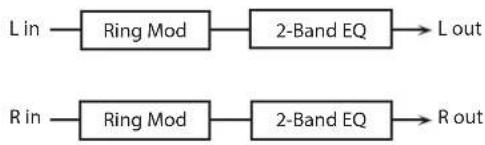
flowchart
graph LR
    A["L in"] --> B["Ring Mod"]
    B --> C["2-Band EQ"]
    C --> D["L out"]
    E["R in"] --> F["Ring Mod"]
    F --> G["2-Band EQ"]
    G --> H["R out"]
Parameter Value Explanation
| FREQUENCY # | 0–127 | Adjusts the frequency at which modulation is applied. |
| SENS # | 0–127 | Adjusts the amount of frequency modulation applied. |
| POLARITY | UP, DOWN | Direction in which the frequency is movedUP: Toward a higher frequencyDOWN: Toward a lower frequency |
| EQ GAIN LOW | -15–+15 dB | Amount of boost/cut for the low-frequency range |
| EQ GAIN HIGH | -15–+15 dB | Amount of boost/cut for the high-frequency range |
| BALANCE # | D100:0W–D0:100W | Volume balance between the direct sound (D) and the effect sound (W) |
| OUTPUT LEVEL | 0–127 Output Level |
16: STEP RING MODULATOR
This is a ring modulator that uses a 16-step sequence to vary the frequency at which modulation is applied.


Parameter Value Explanation
| RATE # | 0.05–10.00 Hz, note | Rate at which the 16-step sequence will cycle |
| ATTACK # | 0–127 | Speed at which the modulation frequency changes between steps |
| EQ GAIN LOW | -15–+15 dB | Amount of boost/cut for the low-frequency range |
| EQ GAIN HIGH | -15–+15 dB | Amount of boost/cut for the high-frequency range |
| BALANCE # | D100:0W–D0:100W | Volume balance of the original sound (D) and effect sound (W) |
| OUTPUT LEVEL | 0–127 Output Level | |
| STEP 1–16 | 0–127 | Frequency of ring modulation at each step |
MEMO
You can use multi-effect control to make the step sequence play again from the beginning (p. 38).
17: TREMOLO
Cyclically modulates the volume to add tremolo effect to the sound.

flowchart
graph LR
    A["L in"] --> B["Tremolo"]
    B --> C["2-Band EQ"] --> D["L out"]
    E["R in"] --> F["Tremolo"]
    F --> G["2-Band EQ"] --> H["R out"]
Parameter Value Explanation
| MOD WAVE | TRI, SQR, SIN, SAW1, SAW2 | Modulation WaveTRI: Triangle waveSQR: Square waveSIN: Sine waveSAW1/2: Sawtooth wave |
| SAW1SAW2 | ||
| RATE # | 0.05–10.00 Hz, note Frequency of the change | |
| DEPTH # | 0–127 Depth to which the effect is applied | |
| EQ GAIN LOW | -15–+15 dB | Amount of boost/cut for the low-frequency range |
| EQ GAIN HIGH | -15–+15 dB | Amount of boost/cut for the high-frequency range |
| OUTPUT LEVEL | 0–127 Output Level | |
18: AUTO PAN
Cyclically modulates the stereo location of the sound.

flowchart
graph LR
    A["L in"] --> B["Auto Pan"]
    B --> C["2-Band EQ"]
    C --> D["L out"]
    E["R in"] --> F["Auto Pan"]
    F --> G["2-Band EQ"]
    G --> H["R out"]
Parameter Value Explanation
| MOD WAVE | TRI, SQR, SIN, SAW1, SAW2 | Modulation WaveTRI: Triangle waveSQR: Square waveSIN: Sine waveSAW1/2: Sawtooth wave |
| SAW1SAW2R | RL | |
| RATE # | 0.05–10.00 Hz, note Frequency of the change | |
| DEPTH # | 0–127 Depth to which the effect is applied | |
| EQ GAIN LOW | -15–+15 dB | Amount of boost/cut for the low-frequency range |
| EQ GAIN HIGH | -15–+15 dB | Amount of boost/cut for the high-frequency range |
| OUTPUT LEVEL | 0–127 Output Level | |
19: STEP PAN
This uses a 16-step sequence to vary the panning of the sound.
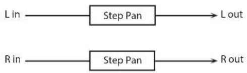
flowchart
graph LR
    A["L in"] --> B["Step Pan"] --> C["L out"]
    D["R in"] --> E["Step Pan"] --> F["R out"]
Parameter Value Explanation
| RATE # | 0.05–10.00 Hz, note | Rate at which the 16-step sequence will cycle |
| ATTACK # | 0–127 | Speed at which the pan changes between steps |
| INPUT SYNC SW | OFF, ON | Specifies whether an input note will cause the sequence to resume from the first step of the sequence (ON) or not (OFF) |
| INPUT SYNC THRESHOLD | 0–127 | Volume at which an input note will be detected |
| OUTPUT LEVEL | 0–127 Output Level | |
| STEP 1–16 | L64–G3R Pan at each step | |
MEMO
You can use multi-effect control to make the step sequence play again from the beginning (p. 38).
20: SLICER
By applying successive cuts to the sound, this effect turns a conventional sound into a sound that appears to be played as a backing phrase. This is especially effective when applied to sustain-type sounds.

flowchart
graph LR
    A["L in"] --> B["Slicer"] --> C["L out"]
    D["R in"] --> E["Slicer"] --> F["R out"]
| Parameter Value Explanation | ||
| RATE # | 0.05-10.00 Hz, note | Rate at which the 16-step sequence will cycle |
| ATTACK # | 0-127 | Speed at which the level changes between steps |
| MODE | LEGATO, SLASH | Sets the manner in which the volume changes as one step progresses to the next.LEGATO: The change in volume from one step's level to the next remains unaltered. If the level of a following step is the same as the one preceding it, there is no change in volume.SLASH: The level is momentarily set to 0 before progressing to the level of the next step. This change in volume occurs even if the level of the following step is the same as the preceding step. |
| SHUFFLE # | 0-127 | Timing when to shift to even-numbered steps (step 2, step 4, step 6...).The higher the value, the later the beat progresses. |
| INPUT SYNC SW | OFF, ON | Specifies whether an input note will cause the sequence to resume from the first step of the sequence (ON) or not (OFF) |
| INPUT SYNC THRESHOLD | 0-127 | Volume at which an input note will be detected |
| OUTPUT LEVEL | 0-127 Output Level | |
| STEP 1-16 | 0-127 Level at each step | |
MEMO
You can use multi-effect control to make the step sequence play again from the beginning (p. 38).
21: ROTARY
This simulates a classic rotary speaker of the past.
Since the operation of the high-frequency and low-frequency rotors can be specified independently, the distinctive modulation can be reproduced realistically. This is most effective on organ patches.

flowchart
graph LR
    A["L in"] --> C["+"]
    B["R in"] --> C["+"]
    C["+"] --> D["Rotary"]
    D --> E["L out"]
    D --> F["R out"]
Parameter Value Explanation
| SPEED # | SLOW, FAST | Simultaneously switch the rotational speed of the low frequency rotor and high frequency rotor.SLOW: Slows down the rotation to the Slow Rate.FAST: Speeds up the rotation to the Fast Rate. |
| WOOFER SLOW | 0.05–10.00 Hz | Slow speed (SLOW) of the low frequency rotor |
| WOOFER FAST | 0.05–10.00 Hz | Fast speed (FAST) of the low frequency rotor |
| WOOFER ACCEL | 0–15 | Adjusts the time it takes the low frequency rotor to reach the newly selected speed when switching from fast to slow (or slow to fast) speed.Lower values will require longer times. |
| WOOFER LEVEL | 0–127 Volume of the low frequency rotor | |
| TWEETER SLOW | 0.05–10.00 Hz | Settings of the high frequency rotorThe parameters are the same as for the low frequency rotor |
| TWEETER FAST | 0.05–10.00 Hz | |
| TWEETER ACCEL | 0–15 | |
| TWEETER LEVEL | 0–127 | |
| SEPARATION | 0–127 Spatial dispersion of the sound | |
| OUTPUT LEVEL # | 0–127 Output Level | |
22: VK ROTARY
This type provides modified response for the rotary speaker, with the low end boosted further.
This effect features the same specifications as the VK-7's built-in rotary speaker.
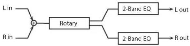
flowchart
graph LR
    A["L in"] --> C["+"]
    B["R in"] --> C
    C --> D["Rotary"]
    D --> E["2-Band EQ"]
    D --> F["2-Band EQ"]
    E --> G["L out"]
    F --> H["R out"]
Parameter Value Explanation
| SPEED # | SLOW, FAST | Rotational speed of the rotating speakerSLOW: Slows down the rotation to the Slow Rate.FAST: Speeds up the rotation to the Fast Rate. |
| BRAKE # | OFF, ON | Switches the rotation of the rotary speaker.When this is turned on, the rotation will gradually stop. When it is turned off, the rotation will gradually resume. |
| WOOFER SLOW | 0.05–10.00 Hz | Low-speed rotation speed of the woofer |
| WOOFER FAST | 0.05–10.00 Hz | High-speed rotation speed of the woofer |
| WOOFER TRANS UP | 0–127 | Adjusts the rate at which the woofer rotation speeds up when the rotation is switched from Slow to Fast. |
| WOOFER TRANS DOWN | 0–127 | Adjusts the rate at which the woofer rotation speeds up when the rotation is switched from Fast to Slow. |
| WOOFER LEVEL | 0–127 Volume of the woofer | |
| TWEETER SLOW | 0.05–10.00 Hz | Settings of the tweeterThe parameters are the same as for the woofer. |
| TWEETER FAST | 0.05–10.00 Hz | |
| TWEETER TRANS UP | 0–127 | |
| TWEETER TRANS DOWN | 0–127 | |
| TWEETER LEVEL | 0–127 | |
| SPREAD | 0–10 | Sets the rotary speaker stereo image.The higher the value set, the wider the sound is spread out. |
| EQ GAIN LOW | -15–+15 dB | Amount of boost/cut for the low-frequency range |
| EQ GAIN HIGH | -15–+15 dB | Amount of boost/cut for the high-frequency range |
| OUTPUT LEVEL # | 0–127 Output Level | |
23: CHORUS
This is a stereo chorus. A filter is provided so that you can adjust the timbre of the chorus sound.

flowchart
graph LR
    L_in --> A["Chorus"]
    A --> B["Balance D"]
    B --> C["+"]
    C --> D["2-Band EQ"]
    D --> E["L out"]
    R_in --> F["Chorus"]
    F --> G["Balance D"]
    G --> H["+"]
    H --> I["2-Band EQ"]
    I --> J["R out"]
    C --> K["Balance W"]
    H --> L["Balance W"]
Parameter Value Explanation
| CHORUS RATE # | 0.05–10.00 Hz, note Frequency of modulation | |
| CHORUS DEPTH | 0–127 Depth of modulation | |
| CHORUS PHASE | 0–180 deg Spatial spread of the sound | |
| CHORUS PRE DELAY | 0.0–100 msec | Adjusts the delay time from the direct sound until the chorus sound is heard. |
| FILTER TYPE | OFF, LPF, HPF | Type of filterOFF: no filter is usedLPF: cuts the frequency range above the Cutoff FreqHPF: cuts the frequency range below the Cutoff Freq |
| FILTER CUTOFF | 200–8000 Hz | Center frequency when using the filter to cut a specific frequency range |
| EQ GAIN LOW | -15–+15 dB | Amount of boost/cut for the low-frequency range |
| EQ GAIN HIGH | -15–+15 dB | Amount of boost/cut for the high-frequency range |
| BALANCE # | D100:0W–D0:100W | Volume balance between the direct sound (D) and the chorus sound (W) |
| OUTPUT LEVEL | 0–127 Output Level | |
24: FLANGER
This is a stereo flanger. (The LFO has the same phase for left and right.) It produces a metallic resonance that rises and falls like a jet airplane taking off or landing. A filter is provided so that you can adjust the timbre of the flanged sound.

flowchart
graph TD
    A["L in"] --> B["+"]
    B --> C["Flanger"]
    C --> D["+"]
    D --> E["2-Band EQ"]
    E --> F["L out"]
    G["R in"] --> H["+"]
    H --> I["Flanger"]
    I --> J["+"]
    J --> K["2-Band EQ"]
    K --> L["R out"]
    M["Balance D"] --> B
    N["Balance W"] --> D
    O["Feedback Feedback"] --> C
    P["Balance W"] --> J
    Q["Balance D"] --> H
Parameter Value Explanation
| FLANGER RATE # | 0.05–10.00 Hz, note Frequency of modulation | |
| FLANGER DEPTH | 0–127 Depth of modulation | |
| FLANGER FEEDBACK # | -98–+98 % | Adjusts the proportion of the flanger sound that is fed back into the effect. Negative (-) settings will invert the phase. |
| FLANGER PHASE | 0–180 deg Spatial spread of the sound | |
| FLANGER PRE DELAY | 0.0–100 msec | Adjusts the delay time from when the direct sound begins until the flanger sound is heard. |
| FILTER TYPE | OFF, LPF, HPF | Type of filterOFF: no filter is usedLPF: cuts the frequency range above the Cutoff FreqHPF: cuts the frequency range below the Cutoff Freq |
| FILTER CUTOFF | 200–8000 Hz | Center frequency when using the filter to cut a specific frequency range |
| EQ GAIN LOW | -15–+15 dB | Amount of boost/cut for the low-frequency range |
| EQ GAIN HIGH | -15–+15 dB | Amount of boost/cut for the high-frequency range |
| BALANCE # | D100:0W–D0:100W | Volume balance between the direct sound (D) and the flanger sound (W) |
| OUTPUT LEVEL | 0–127 Output Level | |
25: STEP FLANGER
This is a flanger in which the flanger pitch changes in steps. The speed at which the pitch changes can also be specified in terms of a note-value of a specified tempo.

flowchart
graph TD
    A["L in"] --> B["+"]
    B --> C["Step Flanger"]
    C --> D["+"]
    D --> E["2-Band EQ"]
    E --> F["L out"]
    G["R in"] --> H["+"]
    H --> I["Step Flanger"]
    I --> J["+"]
    J --> K["2-Band EQ"]
    K --> L["R out"]
    M["Balance D"] --> B
    N["Balance W"] --> D
    O["Feedback Feedback"] --> C
    P["Balance W"] --> J
    Q["Balance D"] --> H
Parameter Value Explanation
| FLANGER RATE # | 0.05–10.00 Hz, note Frequency of modulation | |
| FLANGER DEPTH | 0–127 Depth of modulation | |
| FLANGER FEEDBACK # | -98–+98 % | Adjusts the proportion of the flanger sound that is fed back into the effect. Negative (-) settings will invert the phase. |
| FLANGER PHASE | 0–180 deg Spatial spread of the sound | |
| FLANGER PRE DELAY | 0.0–100 msec | Adjusts the delay time from when the direct sound begins until the flanger sound is heard. |
| FILTER TYPE | OFF, LPF, HPF | Type of filterOFF: no filter is usedLPF: cuts the frequency range above the Cutoff FreqHPF: cuts the frequency range below the Cutoff Freq |
| FILTER CUTOFF | 200–8000 Hz | Center frequency when using the filter to cut a specific frequency range |
| STEP RATE # | 0.10–20.00 Hz, note Rate (period) of pitch change | |
| EQ GAIN LOW | -15–+15 dB | Amount of boost/cut for the low-frequency range |
| EQ GAIN HIGH | -15–+15 dB | Amount of boost/cut for the high-frequency range |
| BALANCE # | D100:0W–D0:100W | Volume balance between the direct sound (D) and the flanger sound (W) |
| OUTPUT LEVEL | 0–127 Output Level | |
26: HEXA-CHORUS
Uses a six-phase chorus (six layers of chorused sound) to give richness and spatial spread to the sound.

flowchart
graph LR
    L_in --> A["+"]
    R_in --> A
    A --> B["Balance D"]
    B --> C["+"]
    R_out --> D["Balance D"]
    D --> E["R out"]
    C --> F["Balance W"]
    F --> G["+"]
    H["Hexa Chorus"] --> I["Balance D"]
    I --> J["+"]
    H --> K["Balance W"]
    K --> L["+"]
    H --> M["Balance D"]
    M --> N["+"]
    H --> O["Balance W"]
    O --> P["+"]
    H --> Q["Balance D"]
    Q --> R
Parameter Value Explanation
| RATE # | 0.05-10.00 Hz, note Frequency of modulation | |
| DEPTH | 0-127 Depth of modulation | |
| DEPTH DEVIATION | -20-+20 | Adjusts the difference in modulation depth between each chorus sound. |
| PRE DELAY | 0.0-100 msec | Adjusts the delay time from the direct sound until the chorus sound is heard. |
| DELAY DEVIATION | 0-20 | Adjusts the differences in Pre Delay between each chorus sound. |
| PAN DEVIATION | 0-20 | Adjusts the difference in stereo location between each chorus sound.0: All chorus sounds will be in the center.20: Each chorus sound will be spaced at 60 degree intervals relative to the center. |
| BALANCE # | D100:0W-D0:100W | Volume balance between the direct sound (D) and the chorus sound (W) |
| OUTPUT LEVEL | 0-127 Output Level | |
27: TREMOLO CHORUS
This is a chorus effect with added Tremolo (cyclic modulation of volume).

flowchart
graph LR
    L_in --> A["+"]
    R_in --> A
    A --> B["Tremolo Chorus"]
    B --> C["+"]
    L_out --> C
    R_out --> C
    C --> D["Balance D"]
    C --> E["Balance W"]
    D --> F["+"]
    E --> G["+"]
    F --> H["L out"]
    G --> I["R out"]
Parameter Value Explanation
| CHORUS RATE # | 0.05–10.00 Hz, note | Modulation frequency of the chorus effect |
| CHORUS DEPTH | 0–127 | Modulation depth of the chorus effect |
| CHORUS PRE DELAY | 0.0–100 msec | Adjusts the delay time from the direct sound until the chorus sound is heard. |
| TREMOLO RATE # | 0.05–10.00 Hz, note | Adjusts the modulation speed of the tremolo effect. |
| TREMOLO PHASE | 0–180 deg | Adjusts the width of the tremolo sound. |
| TREMOLO SEPARATION | 0–127 | Adjusts the spatial spread of the tremolo effect. |
| BALANCE # | D100:0W–D0:100W | Volume balance between the direct sound (D) and the tremolo chorus sound (W) |
| OUTPUT LEVEL | 0–127 Output Level |
28: SPACE-D
This is a multiple chorus that applies two-phase modulation in stereo. It gives no impression of modulation, but produces a transparent chorus effect.

flowchart
graph LR
    L_in --> A1["Balance D"]
    A1 --> B1["+"]
    B1 --> C1["2-Band EQ"]
    C1 --> L_out["L out"]
    R_in --> A2["Balance D"]
    A2 --> B2["+"]
    B2 --> C2["2-Band EQ"]
    C2 --> R_out["R out"]
    A1 -->|Balance D| B1
    A2 -->|Balance D| B2
    B1 -->|Balance W| C1
    B2 -->|Balance W| C2
Parameter Value Explanation
| RATE # | 0.05–10.00 Hz, note Frequency of modulation | |
| DEPTH | 0–127 Depth of modulation | |
| PHASE | 0–180 deg Spatial spread of the sound | |
| PRE DELAY | 0.0–100 msec | Adjusts the delay time from the direct sound until the chorus sound is heard. |
| EQ GAIN LOW | -15–+15 dB | Amount of boost/cut for the low-frequency range |
| EQ GAIN HIGH | -15–+15 dB | Amount of boost/cut for the high-frequency range |
| BALANCE # | D100:0W–D0:100W | Volume balance between the direct sound (D) and the chorus sound (W) |
| OUTPUT LEVEL | 0–127 Output Level | |
29: 3D CHORUS
This applies a 3D effect to the chorus sound. The chorus sound will be positioned 90 degrees left and 90 degrees right.
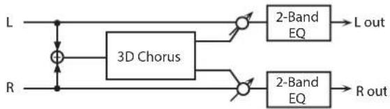
flowchart
graph LR
    L --> A["+"]
    R --> B["3D Chorus"]
    A --> C["2-Band EQ"]
    B --> D["2-Band EQ"]
    C --> E["L out"]
    D --> F["R out"]
Parameter Value Explanation
| RATE # | 0.05–10.00 Hz, note | Modulation frequency of the chorus effect |
| DEPTH | 0–127 | Modulation depth of the chorus effect |
| PHASE | 0–180 deg Spatial spread of the sound | |
| PRE DELAY | 0.0–100 msec | Adjusts the delay time from the direct sound until the chorus sound is heard. |
| FILTER TYPE | OFF, LPF, HPF | Type of filterOFF: no filter is usedLPF: cuts the frequency range above the Cutoff FreqHPF: cuts the frequency range below the Cutoff Freq |
| CUTOFF | 200–8000 Hz | Center frequency when using the filter to cut a specific frequency range |
| EQ GAIN LOW | -15–+15 dB | Amount of boost/cut for the low-frequency range |
| EQ GAIN HIGH | -15–+15 dB | Amount of boost/cut for the high-frequency range |
| BALANCE # | D100:0W–D0:100W | Volume balance between the direct sound (D) and the chorus sound (W) |
| OUTPUT MODE | SPEAKER, PHONES | Adjusts the method that will be used to hear the sound that is output to the OUTPUT. The optimal 3D effect will be achieved if you select SPEAKER when using speakers, or PHONES when using headphones. |
| OUTPUT LEVEL | 0–127 Output Level | |
30: 3D FLANGER
This applies a 3D effect to the flanger sound. The flanger sound will be positioned 90 degrees left and 90 degrees right.

flowchart
graph LR
    L --> A["+"]
    R --> B["-"]
    A --> C["3D Flanger"]
    B --> C
    C --> D["2-Band EQ"] --> E["L out"]
    C --> F["2-Band EQ"] --> G["R out"]
| Parameter Value Explanation | ||
| RATE # | 0.05–10.00 Hz, note | Modulation frequency of the flanger effect |
| DEPTH | 0–127 | Modulation depth of the flanger effect |
| FEEDBACK # | -98–+98 % | Adjusts the proportion of the flanger sound that is fed back into the effect. Negative (-) settings will invert the phase. |
| PHASE | 0–180 deg Spatial spread of the sound | |
| PRE DELAY | 0.0–100 msec | Adjusts the delay time from when the direct sound begins until the flanger sound is heard. |
| FILTER TYPE | OFF, LPF, HPF | Type of filterOFF: no filter is usedLPF: cuts the frequency range above the Cutoff FreqHPF: cuts the frequency range below the Cutoff Freq |
| CUTOFF | 200–8000 Hz | Center frequency when using the filter to cut a specific frequency range |
| EQ GAIN LOW | -15–+15 dB | Amount of boost/cut for the low-frequency range |
| EQ GAIN HIGH | -15–+15 dB | Amount of boost/cut for the high-frequency range |
| BALANCE # | D100:0W–D0:100W | Volume balance between the direct sound (D) and the flanger sound (W) |
| OUTPUT MODE | SPEAKER, PHONES | Adjusts the method that will be used to hear the sound that is output to the OUTPUT. The optimal 3D effect will be achieved if you select SPEAKER when using speakers, or PHONES when using headphones. |
| OUTPUT LEVEL | 0–127 Output Level | |
31: 3D STEP FLANGER
This applies a 3D effect to the step flanger sound. The flanger sound will be positioned 90 degrees left and 90 degrees right.

flowchart
graph LR
    L --> A["+"]
    R --> B["-"]
    A --> C["3D Step Flanger"]
    B --> C
    C --> D["2-Band EQ"] --> E["L out"]
    C --> F["2-Band EQ"] --> G["R out"]
| Parameter Value Explanation | ||
| RATE # | 0.05–10.00 Hz, note | Modulation frequency of the flanger effect |
| DEPTH | 0–127 | Modulation depth of the flanger effect |
| FEEDBACK # | -98–+98 % | Adjusts the proportion of the flanger sound that is fed back into the effect. Negative (-) settings will invert the phase. |
| PHASE | 0–180 deg Spatial spread of the sound | |
| PRE DELAY | 0.0–100 msec | Adjusts the delay time from when the direct sound begins until the flanger sound is heard. |
| FILTER TYPE | OFF, LPF, HPF | Type of filterOFF: no filter is usedLPF: cuts the frequency range above the Cutoff FreqHPF: cuts the frequency range below the Cutoff Freq |
| CUTOFF | 200–8000 Hz | Center frequency when using the filter to cut a specific frequency range |
| STEP RATE # | 0.10–20.00 Hz, note Rate (period) of pitch change | |
| OUTPUT MODE | SPEAKER, PHONES | Adjusts the method that will be used to hear the sound that is output to the OUTPUT. The optimal 3D effect will be achieved if you select SPEAKER when using speakers, or PHONES when using headphones. |
| EQ GAIN LOW | -15–+15 dB | Amount of boost/cut for the low-frequency range |
| EQ GAIN HIGH | -15–+15 dB | Amount of boost/cut for the high-frequency range |
| BALANCE # | D100:0W–D0:100W | Volume balance between the direct sound (D) and the flanger sound (W) |
| OUTPUT LEVEL | 0–127 Output Level | |
32: 2 BAND CHORUS
A chorus effect that lets you apply an effect independently to the low-frequency and high-frequency ranges.

flowchart
graph LR
    L_in --> Split1["Split"]
    Split1 --> HighBandChorus1["High Band Chorus"]
    Split1 --> LowBandChorus2["Low Band Chorus"]
    Split1 --> HighBandChorus3["High Band Chorus"]
    Split1 --> LowBandChorus4["Low Band Chorus"]
    HighBandChorus1 --> L_out
    LowBandChorus2 --> L_out
    HighBandChorus3 --> L_out
    LowBandChorus4 --> L_out
    R_in --> Split2["Split"]
    Split2 --> HighBandChorus5["High Band Chorus"]
    Split2 --> LowBandChorus6["Low Band Chorus"]
    R_out --> L_out
    R_in --> R_out
Parameter Value Explanation
| LOW RATE # | 0.05–10.00 Hz, note | Rate at which the low-range chorus sound is modulated |
| LOW DEPTH | 0–127 | Modulation depth for the low-range chorus sound |
| LOW PHASE | 0–180 deg | Spaciousness of the low-range chorus sound |
| LOW PRE DELAY | 0.0–100 msec | Delay time from when the original sound is heard to when the low-range chorus sound is heard |
| HIGH RATE # | 0.05–10.00 Hz, note | Rate at which the high-range chorus sound is modulated |
| HIGH DEPTH | 0–127 | Modulation depth for the high-range chorus sound |
| HIGH PHASE | 0–180 deg | Spaciousness of the high-range chorus sound |
| HIGH PRE DELAY | 0.0–100 msec | Delay time from when the original sound is heard to when the high-range chorus sound is heard |
| SPLIT FREQUENCY | 200–8000 Hz | Frequency at which the low and high ranges will be divided |
| BALANCE # | D100:0W–D0:100W | Volume balance of the original sound (D) and chorus sound (W) |
| OUTPUT LEVEL | 0–127 Output Level |
33: 2 BAND FLANGER
A flanger that lets you apply an effect independently to the low-frequency and high-frequency ranges.

flowchart
graph TD
    A["L in"] --> B["Split"]
    B --> C1["High Band Flanger"]
    B --> C2["Low Band Flanger"]
    C1 --> D1["L out"]
    C2 --> D2["L out"]
    D1 --> E1["R in"]
    D2 --> E2["R out"]
    E1 --> F1["Split"]
    E2 --> F2["High Band Flanger"]
    E2 --> F3["Low Band Flanger"]
    F1 --> G1["High Band Flanger"]
    F2 --> G2["High Band Flanger"]
    F3 --> G3["Low Band Feedback"]
    G1 --> H1["High Band Feedback"]
    G2 --> H2["Low Band Feedback"]
    H1 --> I1["Output"]
    H2 --> I2["Output"]
    I1 --> J1["Output"]
    I2 --> J2["Output"]
| Parameter Value Explanation | ||
| LOW RATE # | 0.05–10.00 Hz, note | Rate at which the low-range flanger sound is modulated |
| LOW DEPTH | 0–127 | Modulation depth for the low-range flanger sound |
| LOW FEEDBACK # | 98–+98 % | Proportion of the low-range flanger sound that is to be returned to the input (negative values invert the phase) |
| LOW PHASE | 0–180 deg | Spaciousness of the low-range flanger sound |
| LOW PRE DELAY | 0.0–100 msec | Delay time from when the original sound is heard to when the low-range flanger sound is heard |
| HIGH RATE # | 0.05–10.00 Hz, note | Rate at which the high-range flanger sound is modulated |
| HIGH DEPTH | 0–127 | Modulation depth for the high-range flanger sound |
| HIGH FEEDBACK # | -98–+98 % | Proportion of the high-range flanger sound that is to be returned to the input (negative values invert the phase) |
| HIGH PHASE | 0–180 deg | Spaciousness of the high-range flanger sound |
| HIGH PRE DELAY | 0.0–100 msec | Delay time from when the original sound is heard to when the high-range flanger sound is heard |
| SPLIT FREQUENCY | 200–8000 Hz | Frequency at which the low and high ranges will be divided |
| BALANCE # | D100:0W–D0:100W | Volume balance of the original sound (D) and flanger sound (W) |
| OUTPUT LEVEL | 0–127 Output Level | |
34: 2 BAND STEP FLANGER
A step flanger that lets you apply an effect independently to the low-frequency and high-frequency ranges.

flowchart
graph TD
    A["L in"] --> B["Split"]
    B --> C1["High Band Step Flanger"]
    B --> C2["Low Band Step Flanger"]
    C1 --> D1["L out"]
    C2 --> D2["R out"]
    D1 --> E1["Output"]
    D2 --> F1["Output"]
    G["R in"] --> H["Split"]
    H --> I1["High Band Step Flanger"]
    H --> I2["Low Band Step Flanger"]
    I1 --> J1["Output"]
    I2 --> J2["R out"]
    style A fill:#f9f,stroke:#333
    style G fill:#f9f,stroke:#333
Parameter Value Explanation
| LOW RATE # | 0.05–10.00 Hz, note | Rate at which the low-range flanger sound is modulated |
| LOW DEPTH | 0–127 | Modulation depth for the low-range flanger sound |
| LOW FEEDBACK # | -98–+98 % | Proportion of the low-range flanger sound that is to be returned to the input (negative values invert the phase) |
| LOW PHASE | 0–180 deg | Spaciousness of the low-range flanger sound |
| LOW PRE DELAY | 0.0–100 msec | Delay time from when the original sound is heard to when the low-range flanger sound is heard |
| HIGH RATE # | 0.05–10.00 Hz, note | Rate at which the high-range flanger sound is modulated |
| HIGH DEPTH | 0–127 | Modulation depth for the high-range flanger sound |
| HIGH FEEDBACK # | -98–+98 % | Proportion of the high-range flanger sound that is to be returned to the input (negative values invert the phase) |
| HIGH PHASE | 0–180 deg | Spaciousness of the high-range flanger sound |
| HIGH PRE DELAY | 0.0–100 msec | Delay time from when the original sound is heard to when the high-range flanger sound is heard |
| LOW STEP RATE # | 0.10–20.00 Hz, note | Rate at which the steps will cycle for the low-range flanger sound |
| HIGH STEP RATE # | 0.10–20.00 Hz, note | Rate at which the steps will cycle for the high-range flanger sound |
| SPLIT FREQUENCY | 200–8000 Hz | Frequency at which the low and high ranges will be divided |
| BALANCE # | D100:0W–D0:100W | Volume balance of the original sound (D) and flanger sound (W) |
| OUTPUT LEVEL | 0–127 Output Level |
35: OVERDRIVE
Creates a soft distortion similar to that produced by vacuum tube amplifiers.

flowchart
graph LR
    A["L in"] --> C["+"]
    B["R in"] --> C
    C --> D["Over drive"]
    D --> E["Amp Simulator"]
    E --> F["2-Band EQ"]
    F --> G["L out"]
    F --> H["Pan L"]
    F --> I["Pan R"]
    F --> J["R out"]
Parameter Value Explanation
| DRIVE # | 0-127 | Degree of distortionAlso changes the volume. |
| AMP SIMULATOR TYPE | SMALL,BUILT-IN,2-STACK,3-STACK | Type of guitar ampSMALL: small ampBUILT-IN: single-unit type amp2-STACK: large double stack amp3-STACK: large triple stack amp |
| EQ GAIN LOW | -15-+15 dB | Amount of boost/cut for the low-frequency range |
| EQ GAIN HIGH | -15-+15 dB | Amount of boost/cut for the high-frequency range |
| OUTPUT PAN # | L64-63R Stereo location of the output sound | |
| OUTPUT LEVEL | 0-127 Output Level | |
36: DISTORTION
Produces a more intense distortion than Overdrive. The parameters are the same as for "35: OVERDRIVE."
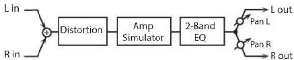
flowchart
graph LR
    A["L in"] --> B["+"]
    C["R in"] --> B
    B --> D["Distortion"]
    D --> E["Amp Simulator"]
    E --> F["2-Band EQ"]
    F --> G["Pan L"]
    F --> H["Pan R"]
    F --> I["R out"]
37: VS OVERDRIVE
This is an overdrive that provides heavy distortion.

flowchart
graph LR
    A["L in"] --> C["+"]
    B["R in"] --> C["+"]
    C["+"] --> D["Overdrive"]
    D["Overdrive"] --> E["Amp Simulator"]
    E["Amp Simulator"] --> F["2-Band EQ"]
    F["2-Band EQ"] --> G["L out"]
    F["2-Band EQ"] --> H["L out"]
    F["2-Band EQ"] --> I["L out"]
    F["2-Band EQ"] --> J["L out"]
    F["2-Band EQ"] --> K["L out"]
    F["2-Band EQ"] --> L["L out"]
    F["2-Band EQ"] --> M["L out"]
    F["2-Band EQ"] --> N["L out"]
    F["2-Band EQ"] --> O["L out"]
    F["2-Band EQ"] --> P["L out"]
    F["2-Band EQ"] --> Q["L out"]
    F["2-Band EQ"] --> R["L out"]
    F["2-Band EQ"] --> S["L out"]
    F["2-Band EQ"] --> T["L out"]
    F["2-Band EQ"] --> U["L out"]
    F["2-Band EQ"] --> V["L out"]
    F["2-Band EQ"] --> W["L out"]
    F["2-Band EQ"] --> X["L out"]
    F["2-Band EQ"] --> Y["L out"]
    F["2-Band EQ"] --> Z["L out"]
    F["2-Band EQ"] --> AA["L out"]
    F["2-Band EQ"] --> AB["L out"]
    F["2-Band EQ"] --> AC["L out"]
    F["2-Band EQ"] --> AD["L out"]
    F["2-Band EQ"] --> AE["L out"]
    F["2-Band EQ"] --> AF["L out"]
    F["2-Band EQ"] --> AG["L out"]
    F["2-Band EQ"] --> AH["L out"]
    F["2-Band EQ"] --> AI["L out"]
    F["2-Band EQ"] --> AJ["L out"]
    F["2-Band EQ"] --> AK["L out"]
    F["2-Band EQ"] --> AL["L out"]
    F["2-Band EQ"] --> AM["L out"]
    F["2-Band EQ"] --> AN["L out"]
    F["2-Band EQ"] --> AO["L out"]
    F["2-Band EQ"] --> AP["L out"]
    F["2-Band EQ"] --> AQ["L out"]
    F["2-Band EQ"] --> AR["L out"]
    F["2-Band EQ"] --> AS["L out"]
    F["2-Band EQ"] --> AT["L out"]
    F["2-Band EQ"] --> AU["L out"]
    F["2-Band EQ"] --> AV["L out"]
    F["2-Band EQ"] --> AW["L out"]
    F["2-Band EQ"] --> AX["L out"]
    F["2-Band EQ"] --> AY["L out"]
    F["2-Band EQ"] --> AZ["L out"]
    F["2-Band EQ"] --> BA["L out"]
    F["2-Band EQ"] --> BB["L out"]
    F["2-Band EQ"] --> BC["L out"]
    F["2-Band EQ"] --> BD["L out"]
    F["2-Band EQ"] --> BE["L out"]
    F["2-Band EQ"] --> BF["L out"]
    F["2-Band EQ"] --> BG["L out"]
    F["2-Band EQ"] --> BH["L out"]
    F["2-Band EQ"] --> BI["L out"]
    F["2-Band EQ"] --> BJ["L out"]
    F["2-Band EQ"] --> BK["L out"]
    F["2-Band EQ"] --> BL["L out"]
    F["2-Band EQ"] --> BM["L out"]
    F["2-Band EQ"] --> BN["L out"]
    F["2-Band EQ"] --> BO["L out"]
    F["2-Band EQ"] --> BP["L out"]
    F["2-Band EQ"] --> BQ["L out"]
    F["2-Band EQ"] --> BR["L out"]
    F["2-Band EQ"] --> BS["L out"]
    F["2-Band EQ"] --> BT["L out"]
    F["2-Band EQ"] --> BU["L out"]
    F["2-Band EQ"] --> BV["L out"]
    F["2-Band EQ"] --> BW["L out"]
    F["2-Band EQ"] --> BX["L out"]
    F["2-Band EQ"] --> BY["L out"]
    F["2-Band EQ"] --> BZ["L out"]
    F["2-Band EQ"] --> CA["L out"]
    F["2-Band EQ"] --> CB["L out"]
    F["2-Band EQ"] --> CC["L out"]
    F["2-Band EQ"] --> DD["L out"]
    F["2-Band EQ"] --> DE["L out"]
Parameter Value Explanation
| DRIVE # | 0-127 | Degree of distortionAlso changes the volume. |
| TONE # | 0-127 | Sound quality of the Overdrive effect |
| AMP SIMULATOR SW | OFF, ON Turns the Amp Simulator on/off. | |
| AMP SIMULATOR TYPE | SMALL,BUILT-IN,2-STACK,3-STACK | Type of guitar ampSMALL: small ampBUILT-IN: single-unit type amp2-STACK: large double stack amp3-STACK: large triple stack amp |
| EQ GAIN LOW | -15-+15 dB | Amount of boost/cut for the low-frequency range |
| EQ GAIN HIGH | -15-+15 dB | Amount of boost/cut for the high-frequency range |
| OUTPUT PAN # | L64-63R Stereo location of the output sound | |
| OUTPUT LEVEL | 0-127 Output Level | |
38: VS DISTORTION
This is a distortion effect that provides heavy distortion. The parameters are the same as for "37: VS OVERDRIVE."

flowchart
graph LR
    A["L in"] --> B["+"]
    C["R in"] --> B
    B --> D["Distortion"]
    D --> E["Amp Simulator"]
    E --> F["2-Band EQ"]
    F --> G["L out"]
    F --> H["R out"]
    I["Pan L"] --> F
    J["Pan R"] --> F
39: GUITAR AMP SIMULATOR
This is an effect that simulates the sound of a guitar amplifier.

flowchart
graph LR
    A["L in"] --> B["+"]
    C["R in"] --> B
    B --> D["Pre Amp"]
    D --> E["Speaker"]
    E --> F["Pan L"]
    E --> G["Pan R"]
    E --> H["R out"]
Parameter Value Explanation
| AMP SW | OFF, ON Turns the amp switch on/off. | |
| AMP SIMULATOR TYPE | JC-120,CLEAN TWIN,MATCH DRIVE,BG LEAD,MS1959I,MS1959II,MS1959I+II,SLDN LEAD,METAL 5150,METAL LEAD,OD-1,OD-2 TURBO,DISTORTION, FUZZ | Type of guitar amp |
| AMP VOLUME # | 0–127 | Volume and amount of distortion of the amp |
| AMP MASTER # | 0–127 Volume of the entire pre-amp | |
| AMP GAIN | LOW, MIDDLE,HIGH | Amount of pre-amp distortion |
| AMP PRESENCE | 0–127 | Tone for the ultra-high frequency range |
| AMP BRIGHT | OFF, ON | Turning this “On” produces a sharper and brighter sound.* This parameter applies to the "JC-120," "CLEAN TWIN," and "BG LEAD" Pre Amp Types. |
| AMP BASS | 0–127 | Tone of the bass/mid/treble frequency range* Middle cannot be set if “MATCH DRIVE” is selected as the Pre Amp Type. |
| AMP MIDDLE | ||
| AMP TREBLE | ||
| SPEAKER SW | OFF, ON | Selects whether the sound will be sent through the speaker simulation (ON) or not (OFF) |
| SPEAKER TYPE | (See the table below.) Type of speaker | |
| MIC SETTING | 1, 2, 3 | Adjusts the location of the microphone that is recording the sound of the speaker.This can be adjusted in three steps, with the microphone becoming more distant in the order of 1, 2, and 3. |
| MIC LEVEL | 0–127 Volume of the microphone | |
| MIC DIRECT | 0–127 Volume of the direct sound | |
| OUTPUT LEVEL # | 0–127 Output Level | |
| OUTPUT PAN # | L64–63R Stereo location of the output sound | |
Specifications of each Speaker Type
The speaker column indicates the diameter of each speaker unit (in inches) and the number of units.
| Type | Cabinet | Speaker | Microphone |
| SMALL 1 | small open-back enclosure | 10 | dynamic |
| SMALL 2 | small open-back enclosure | 10 | dynamic |
| MIDDLE | open back enclosure | 12 x 1 | dynamic |
| JC-120 | open back enclosure | 12 x 2 | dynamic |
| BUILT-IN 1 | open back enclosure | 12 x 2 | dynamic |
| BUILT-IN 2 | open back enclosure | 12 x 2 | condenser |
| BUILT-IN 3 | open back enclosure | 12 x 2 | condenser |
| BUILT-IN 4 | open back enclosure | 12 x 2 | condenser |
| BUILT-IN 5 | open back enclosure | 12 x 2 | condenser |
| BG STACK 1 | sealed enclosure | 12 x 2 | condenser |
| BG STACK 2 | large sealed enclosure | 12 x 2 | condenser |
| MS STACK 1 | large sealed enclosure | 12 x 4 | condenser |
| MS STACK 2 | large sealed enclosure | 12 x 4 | condenser |
| METAL STACK | large double stack | 12 x 4 | condenser |
| 2-STACK | large double stack | 12 x 4 | condenser |
| 3-STACK | large triple stack | 12 x 4 | condenser |
40: COMPRESSOR
Flattens out high levels and boosts low levels, smoothing out fluctuations in volume.

flowchart
graph LR
    A["L in"] --> B["Compressor"]
    B --> C["2-Band EQ"]
    C --> D["L out"]
    E["R in"] --> F["Compressor"]
    F --> G["2-Band EQ"]
    G --> H["R out"]
Parameter Value Explanation
| ATTACK # | 0-127 | Sets the speed at which compression starts |
| THRESHOLD # | 0-127 | Adjusts the volume at which compression begins |
| POST GAIN | 0-+18 dB | Adjusts the output gain. |
| EQ GAIN LOW | -15-+15 dB | Amount of boost/cut for the low-frequency range |
| EQ GAIN HIGH | -15-+15 dB | Amount of boost/cut for the high-frequency range |
| OUTPUT LEVEL # | 0-127 Output Level |
41: LIMITER
Compresses signals that exceed a specified volume level, preventing distortion from occurring.
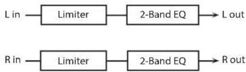
flowchart
graph LR
    A["L in"] --> B["Limiter"]
    B --> C["2-Band EQ"] --> D["L out"]
    E["R in"] --> F["Limiter"]
    F --> G["2-Band EQ"] --> H["R out"]
Parameter Value Explanation
| THRESHOLD # | 0-127 | Adjusts the volume at which compression begins |
| RATIO | 1.5:1, 2:1, 4:1, 100:1 | Compression ratio |
| RELEASE # | 0-127 | Adjusts the time after the signal volume falls below the Threshold Level until compression is no longer applied. |
| POST GAIN | 0-+18 dB | Adjusts the output gain. |
| EQ GAIN LOW | -15-+15 dB | Amount of boost/cut for the low-frequency range |
| EQ GAIN HIGH | -15-+15 dB | Amount of boost/cut for the high-frequency range |
| OUTPUT LEVEL # | 0-127 | Output Level |
42: GATE
Cuts the reverb's decay according to the volume of the sound sent into the effect. Use this when you want to create an artificial-sounding decrease in the reverb's decay.

flowchart
graph LR
    L_in --> Gate1["Gate"]
    R_in --> Gate2["Gate"]
    Gate1 --> L_out
    Gate2 --> Rout
Parameter Value Explanation
| MODE | GATE, DUCK | Type of gateGATE: The gate will close when the volume of the original sound decreases, cutting the original sound.DUCK (Ducking): The gate will close when the volume of the original sound increases, cutting the original sound. |
| ATTACK | 0-127 | Adjusts the time it takes for the gate to fully open after being triggered. |
| HOLD | 0-127 | Adjusts the time it takes for the gate to start closing after the source sound falls beneath the Threshold. |
| RELEASE | 0-127 | Adjusts the time it takes the gate to fully close after the hold time. |
| THRESHOLD # | 0-127 | Volume level at which the gate begins to close |
| BALANCE # | D100:0W-D0:100W | Volume balance between the direct sound (D) and the effect sound (W) |
| OUTPUT LEVEL | 0-127 Output Level |
43: DELAY
This is a stereo delay.
When Feedback Mode is NORMAL:

flowchart
graph TD
    A["L in"] --> B["+"]
    B --> C["Delay"]
    C --> D["+"]
    D --> E["2-Band EQ"]
    E --> F["L out"]
    G["R in"] --> H["+"]
    H --> I["Delay"]
    I --> J["+"]
    J --> K["2-Band EQ"]
    K --> L["R out"]
    M["Balance D"] --> B
    N["Balance W"] --> D
    O["Feedback Feedback"] --> C
    P["Balance D"] --> H
    Q["Balance W"] --> J
When Feedback Mode is CROSS:

flowchart
graph TD
    A["L in"] --> B["+"]
    C["R in"] --> D["+"]
    B --> E["Delay"]
    D --> F["Delay"]
    E --> G["Balance D"]
    F --> H["Balance D"]
    G --> I["2-Band EQ"]
    H --> J["2-Band EQ"]
    I --> K["L out"]
    J --> L["R out"]
    M["Feedback Feedback"] --> N["+"]
    O["Balance W"] --> P["+"]
    Q["Balance W"] --> R["+"]
    S["Balance W"] --> T["+"]
    U["Balance W"] --> V["+"]
    W["Balance W"] --> X["+"]
    Y["Balance W"] --> Z["+"]
    style A fill:#f9f,stroke:#333
    style C fill:#f9f,stroke:#333
    style M fill:#ccf,stroke:#333
    style O fill:#ccf,stroke:#333
    style Q fill:#ccf,stroke:#333
    style U fill:#ccf,stroke:#333
    style V fill:#ccf,stroke:#333
    style X fill:#ccf,stroke:#333
    style Y fill:#ccf,stroke:#333
    style Z fill:#ccf,stroke:#333
Parameter Value Explanation
| DELAY TIME LEFT | 0-1300 msec, note | Adjusts the time until the delay sound is heard. |
| DELAY TIME RIGHT | ||
| FEEDBACK # | -98-+98 % | Adjusts the amount of the delay sound that's fed back into the effect. Negative (-) settings invert the phase. |
| MODE | NORMAL, CROSS | Selects the way in which delay sound is fed back into the effect. (See the figures above.) |
| HF DAMP | 200-8000 Hz, BYPASS | Adjusts the frequency above which sound fed back to the effect is filtered out. If you don't want to filter out any high frequencies, set this parameter to BYPASS. |
| PHASE LEFT | NORMAL, INVERSE | Phase of the delay soundNORMAL: non-invertedINVERT: Inverted |
| PHASE RIGHT | ||
| EQ GAIN LOW | -15-+15 dB | Amount of boost/cut for the low-frequency range |
| EQ GAIN HIGH | -15-+15 dB | Amount of boost/cut for the high-frequency range |
| BALANCE # | D100:0W-D0:100W | Volume balance between the direct sound (D) and the delay sound (W) |
| OUTPUT LEVEL | 0-127 Output Level |
44: LONG DELAY
A delay that provides a long delay time.

flowchart
graph LR
    L_in --> +
    + --> +
    + --> LongDelay
    LongDelay -->
Parameter Value Explanation
| TIME | 0-2600 msec, note | Delay time from when the original sound is heard to when the delay sound is heard |
| FEEDBACK # | -98-+98 % | Proportion of the delay sound that is to be returned to the input (negative values invert the phase) |
| PHASE | NORMAL, INVERSE | Phase of the delayNORMAL: non-invertedINVERT: inverted |
| HF DAMP | 200-8000 Hz, BYPASS | Frequency at which the high-frequency content of the delayed sound will be cut (BYPASS: no cut) |
| PAN # | L64-63R Panning of the delay sound | |
| EQ GAIN LOW | -15-+15 dB | Amount of boost/cut for the low-frequency range |
| EQ GAIN HIGH | -15-+15 dB | Amount of boost/cut for the high-frequency range |
| BALANCE # | D100:0W-D0:100W | Volume balance of the original sound (D) and delay sound (W) |
| OUTPUT LEVEL | 0-127 Output Level | |
45: SERIAL DELAY
This delay connects two delay units in series. Feedback can be applied independently to each delay unit, allowing you to produce complex delay sounds.
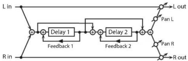
flowchart
graph LR
    L_in --> +1["+"]
    R_in --> +1
    +1 --> Delay1["Delay 1"]
    Delay1 --> +2["+"]
    +2 --> Delay2["Delay 2"]
    Delay2 --> +3["+"]
    +3 --> L_out["L out"]
    +3 --> PanL["Pan L"]
    +3 --> PanR["Pan R"]
    +3 --> Rout["R out"]
    +2 --> Feedback1["Feedback 1"]
    +2 --> Feedback2["Feedback 2"]
Parameter Value Explanation
| DELAY 1 TIME | 0-1300 msec, note | Delay time from when sound is input to delay 1 until the delay sound is heard |
| DELAY 1 FEEDBACK # | -98-+98 % | Proportion of the delay sound that is to be returned to the input of delay 1 (negative values invert the phase) |
| DELAY 1 HF DAMP | 200-8000 Hz, BYPASS | Frequency at which the high-frequency content of the delayed sound of delay 1 will be cut (BYPASS: no cut) |
| DELAY 2 TIME | 0-1300 msec, note | Delay time from when sound is input to delay 2 until the delay sound is heard |
| DELAY 2 FEEDBACK # | -98-+98 % | Proportion of the delay sound that is to be returned to the input of delay 2 (negative values invert the phase) |
| DELAY 2 HF DAMP | 200-8000 Hz, BYPASS | Frequency at which the high-frequency content of the delayed sound of delay 2 will be cut (BYPASS: no cut) |
| PAN # | L64-63R Panning of the delay sound | |
| EQ GAIN LOW | -15-+15 dB | Amount of boost/cut for the low-frequency range |
| EQ GAIN HIGH | -15-+15 dB | Amount of boost/cut for the high-frequency range |
| BALANCE # | D100:0W-D0:100W | Volume balance of the original sound (D) and delay sound (W) |
| OUTPUT LEVEL | 0-127 Output Level | |
46: MODULATION DELAY
Adds modulation to the delayed sound.
When Feedback Mode is NORMAL:
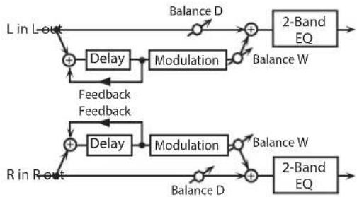
flowchart
graph TD
    A["L in L-out"] --> B["+"]
    B --> C["Delay"]
    C --> D["Modulation"]
    D --> E["+"]
    E --> F["2-Band EQ"]
    F --> G["Balance W"]
    G --> H["+"]
    H --> I["2-Band EQ"]
    I --> J["Balance D"]
    J --> K["+"]
    K --> L["2-Band EQ"]
    L --> M["Balance W"]
    M --> N["+"]
    N --> O["2-Band EQ"]
    O --> P["Balance D"]
    P --> Q["+"]
    Q --> R["2-Band EQ"]
    R --> S["Balance W"]
    S --> T["+"]
    T --> U["2-Band EQ"]
    U --> V["Balance D"]
    V --> W["+"]
    W --> X["2-Band EQ"]
    X --> Y["Balance W"]
    Y --> Z["+"]
    Z --> AA["2-Band EQ"]
    AA --> AB["Balance D"]
    AB --> AC["+"]
    AC --> AD["2-Band EQ"]
    AD --> AE["Balance W"]
    AE --> AF["+"]
    AF --> AG["2-Band EQ"]
    AG --> AH["Balance D"]
    AH --> AI["+"]
    AI --> AJ["2-Band EQ"]
    AJ --> AK["Balance W"]
    AK --> AL["+"]
    AL --> AM["2-Band EQ"]
    AM --> AN["Balance D"]
    AN --> AO["+"]
    AO --> AP["2-Band EQ"]
    AP --> AQ["Balance W"]
    AQ --> AR["+"]
    AR --> AS["2-Band EQ"]
    AS --> AT["Balance D"]
    AT --> AU["+"]
    AU --> AV["2-Band EQ"]
    AV --> AW["Balance W"]
    AW --> AX["+"]
    AX --> AY["2-Band EQ"]
    AY --> AZ["Balance D"]
    AZ --> BA["+"]
    BA --> BB["2-Band EQ"]
    BB --> BC["Balance W"]
    BC --> BD["+"]
    BD --> BE["2-Band EQ"]
    BE --> BF["Balance D"]
    BF --> BG["+"]
    BG --> BH["2-Band EQ"]
    BH --> BI["Balance W"]
    BI --> BJ["+"]
    BJ --> BK["2-Band EQ"]
    BK --> BL["Balance D"]
    BL --> BM["+"]
    BM --> BN["2-Band EQ"]
    BN --> BO["Balance W"]
    BO --> BP["+"]
    BP --> BQ["2-Band EQ"]
    BQ --> BR["Balance D"]
    BR --> BS["+"]
    BS --> BT["2-Band EQ"]
    BT --> BU["Balance W"]
    BU --> BV["+"]
    BV --> BW["2-Band EQ"]
    BW --> BX["Balance D"]
    BX --> BY["+"]
    BY --> BZ["2-Band EQ"]
    BZ --> CA["Balance W"]
    CA --> CB["+"]
    CB --> CC["2-Band EQ"]
    CC --> CD["Balance D"]
    CD --> CE["+"]
    CE --> CF["2-Band EQ"]
    CF --> CG["Balance W"]
    CG --> CH["+"]
    CH --> CI["2-Band EQ"]
    CI --> CJ["Balance D"]
    CJ --> CK["+"]
    CK --> CL["2-Band EQ"]
    CL --> CD
When Feedback Mode is CROSS:

flowchart
graph TD
    A["L in"] --> B["+"]
    C["R in"] --> D["+"]
    B --> E["Delay"]
    D --> F["Delay"]
    E --> G["Modulation"]
    F --> H["Modulation"]
    G --> I["Balance D"]
    H --> J["Balance W"]
    I --> K["2-Band EQ"]
    J --> L["2-Band EQ"]
    K --> M["L out"]
    L --> N["R out"]
    B --> O["Feedback Feedback"]
    D --> P["Feedback Feedback"]
    O --> Q["Balance D"]
    P --> R["Balance W"]
Parameter Value Explanation
| TIME LEFT | 0–1300 msec, note | Adjusts the time until the delay sound is heard. |
| TIME RIGHT | ||
| FEEDBACK # | -98–+98 % | Adjusts the amount of the delay sound that's fed back into the effect. Negative (-) settings invert the phase. |
| MODE | NORMAL, CROSS | Selects the way in which delay sound is fed back into the effect. (See the figures above.) |
| HF DAMP | 200–8000 Hz, BYPASS | Adjusts the frequency above which sound fed back to the effect is filtered out. If you don't want to filter out any high frequencies, set this parameter to BYPASS. |
| RATE # | 0.05–10.00 Hz, note Frequency of modulation | |
| DEPTH | 0–127 Depth of modulation | |
| PHASE | 0–180 deg Spatial spread of the sound | |
| EQ GAIN LOW | -15–+15 dB | Amount of boost/cut for the low-frequency range |
| EQ GAIN HIGH | -15–+15 dB | Amount of boost/cut for the high-frequency range |
| BALANCE # | D100:0W–D0:100W | Volume balance between the direct sound (D) and the delay sound (W) |
| OUTPUT LEVEL | 0–127 Output Level | |
47: 3TAP PAN DELAY
Produces three delay sounds; center, left and right.

flowchart
graph TD
    A["L in"] --> B["+"]
    C["R in"] --> D["+"]
    B --> E["Triple Tap Delay"]
    D --> F["Feedback"]
    E --> G["Center Tap"]
    F --> H["Right Tap"]
    G --> I["+"]
    H --> J["+"]
    I --> K["Balance D"]
    J --> L["Balance W"]
    K --> M["2-Band EQ"]
    L --> N["2-Band EQ"]
    M --> O["L out"]
    N --> P["R out"]
    Q["Balance D"] --> R["+"]
    S["Balance W"] --> T["+"]
    U["Balance D"] --> V["+"]
    W["Balance W"] --> X["+"]
    Y["Balance D"] --> Z["+"]
    AA["Balance W"] --> AB["+"]
    AC["Balance D"] --> AD["+"]
    AE["Balance W"] --> AF["+"]
    AG["Balance D"] --> AH["+"]
    AI["Balance W"] --> AJ["+"]
    AK["Balance D"] --> AL["+"]
    AM["Balance W"] --> AN["+"]
    AO["Balance D"] --> AP["+"]
    AQ["Balance W"] --> AR["+"]
    AS["Balance D"] --> AT["+"]
    AU["Balance W"] --> AV["+"]
    AW["Balance D"] --> AX["+"]
    AY["Left Tap"] --> Z
Parameter Value Explanation
| TIME LEFT/CENTER/RIGHT | 0-2600 msec, note | Adjusts the time from the original sound until the left, center, and right delayed sounds are heard |
| CENTER FEEDBACK # | -98-+98 % | Adjusts the amount of the delay sound that's fed back into the effect. Negative (-) settings invert the phase. |
| HF DAMP | 200-8000 Hz, BYPASS | Adjusts the frequency above which sound fed back to the effect is filtered out. If you do not want to filter out any high frequencies, set this parameter to BYPASS. |
| LEVEL LEFT/CENTER/RIGHT | 0-127 Volume of each delay sound | |
| EQ GAIN LOW | -15-+15 dB | Amount of boost/cut for the low-frequency range |
| EQ GAIN HIGH | -15-+15 dB | Amount of boost/cut for the high-frequency range |
| BALANCE # | D100:0W-D0:100W | Volume balance between the direct sound (D) and the delay sound (W) |
| OUTPUT LEVEL | 0-127 Output Level | |
48: 4TAP PAN DELAY
This effect has four delays.
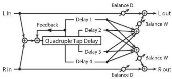
flowchart
graph TD
    A["L in"] --> B["+"]
    C["R in"] --> D["+"]
    B --> E["Feedback"]
    D --> E
    E --> F["Quadruple Tap Delay"]
    F --> G["Delay 1"]
    F --> H["Delay 2"]
    F --> I["Delay 3"]
    F --> J["Delay 4"]
    G --> K["+"]
    H --> K
    I --> K
    J --> K
    K --> L["L out"]
    K --> M["Balance W"]
    K --> N["Balance D"]
    K --> O["R out"]
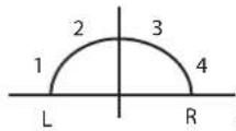
Stereo location of each delay
Parameter Value Explanation
| TIME 1-4 | 0-2600 msec, note | Adjusts the time from the original sound until delay sounds 1-4 are heard |
| LEVEL 1-4 | 0-127 Volume of each delay | |
| DELAY 1 FEEDBACK # | -98-+98 % | Adjusts the amount of the delay sound that's fed back into the effect. Negative (-) settings invert the phase. |
| DELAY 1 HF DAMP | 200-8000 Hz, BYPASS | Adjusts the frequency above which sound fed back to the effect is filtered out. If you do not want to filter out any high frequencies, set this parameter to BYPASS. |
| EQ GAIN LOW | -15-+15 dB | Amount of boost/cut for the low-frequency range |
| EQ GAIN HIGH | -15-+15 dB | Amount of boost/cut for the high-frequency range |
| BALANCE # | D100:0W-D0:100W | Volume balance between the direct sound (D) and the delay sound (W) |
| OUTPUT LEVEL | 0-127 Output Level | |
49: MULTI TAP DELAY
This effect provides four delays. Each of the Delay Time parameters can be set to a note length based on the selected tempo. You can also set the panning and level of each delay sound.

flowchart
graph TD
    L_in -->|Feed back| A["+"]
    R_in -->|Feedback| B["+"]
    A --> C["Multi Tap Delay"]
    B --> C
    C --> D["Delay 1"]
    C --> E["Delay 2"]
    C --> F["Delay 3"]
    C --> G["Delay 4"]
    D --> H["Balance D"]
    E --> I["Balance D"]
    F --> J["Balance D"]
    G --> K["Balance D"]
    H --> L["2-Band EQ"]
    I --> M["2-Band EQ"]
    J --> N["2-Band EQ"]
    K --> O["2-Band EQ"]
    L --> P["L out"]
    M --> Q["R out"]
    N --> R["L out"]
    O --> S["L out"]
Parameter Value Explanation
| TIME 1-4 | 0–2600 msec, note | Adjusts the time until Delays 1–4 are heard. |
| LEVEL 1–4 | 0–127 Output level of Delays 1–4 | |
| DELAY 1 FEEDBACK # | -98–+98 % | Adjusts the amount of the delay sound that's fed back into the effect. Negative (-) settings invert the phase. |
| DELAY 1 HF DAMP | 200–8000 Hz, BYPASS | Adjusts the frequency above which sound fed back to the effect is filtered out. If you don't want to filter out any the high frequencies, set this parameter to BYPASS. |
| PAN 1–4 | L64–63R Stereo location of Delays 1–4 | |
| EQ GAIN LOW | -15–+15 dB | Amount of boost/cut for the low-frequency range |
| EQ GAIN HIGH | -15–+15 dB | Amount of boost/cut for the high-frequency range |
| BALANCE # | D100:0W–D0:100W | Volume balance between the direct sound (D) and the effect sound (W) |
| OUTPUT LEVEL | 0–127 Output Level | |
50: REVERSE DELAY
This is a reverse delay that adds a reversed and delayed sound to the input sound. A tap delay is connected immediately after the reverse delay.
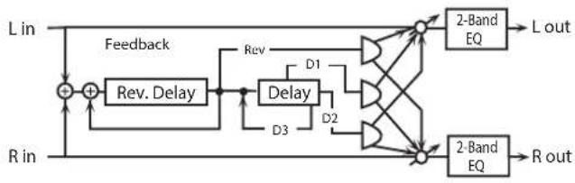
flowchart
graph LR
    L_in --> Feedback
    R_in --> Feedback
    Feedback --> Rev_Delay
    Rev_Delay --> Delay
    Delay --> D1
    Delay --> D2
    D1 --> 2_Band_EQ1["2-Band EQ"]
    D2 --> 2_Band_EQ2["2-Band EQ"]
    2_Band_EQ1 --> L_out["L out"]
    2_Band_EQ2 --> R_out["R out"]
    style Feedback fill:#f9f,stroke:#333
    style Delay fill:#ccf,stroke:#333
    style 2_Band_EQ1 fill:#dfd,stroke:#333
    style 2_Band_EQ2 fill:#dfd,stroke:#333
Parameter Value Explanation
| REV DELAY TIME | 0-1300 msec, note | Delay time from when sound is input into the reverse delay until the delay sound is heard |
| REV DELAY FEEDBACK # | -98-+98 % | Proportion of the delay sound that is to be returned to the input of the reverse delay (negative values invert the phase) |
| REV DELAY HF DAMP | 200-8000 Hz, BYPASS | Frequency at which the high-frequency content of the reverse-delayed sound will be cut (BYPASS: no cut) |
| REV DELAY THRESHOLD | 0-127 | Volume at which the reverse delay will begin to be applied |
| REV DELAY LEVEL | 0-127 Volume of the reverse delay sound | |
| REV DELAY PAN | L64-63R Panning of the reverse delay sound | |
| TAP DELAY TIME 1-3 | 0-1300 msec, note | Delay time from when sound is input into the tap delay until the delay sound is heard |
| DELAY 3 FEEDBACK # | -98-+98 % | Proportion of the delay sound that is to be returned to the input of the tap delay (negative values invert the phase) |
| TAP DELAY HF DAMP | 200-8000 Hz, BYPASS | Frequency at which the high-frequency content of the tap delay sound will be cut (BYPASS: no cut) |
| TAP DELAY PAN 1-2 | L64-63R Panning of the tap delay sounds | |
| TAP DELAY LEVEL 1-2 | 0-127 Volume of the tap delay sounds | |
| EQ GAIN LOW | -15-+15 dB | Amount of boost/cut for the low-frequency range |
| EQ GAIN HIGH | -15-+15 dB | Amount of boost/cut for the high-frequency range |
| BALANCE # | D100:0W-D0:100W | Volume balance of the original sound (D) and delay sound (W) |
| OUTPUT LEVEL | 0-127 Output Level | |
51: SHUFFLE DELAY
Adds a shuffle to the delay sound, giving the sound a bouncy delay effect with a swing feel.
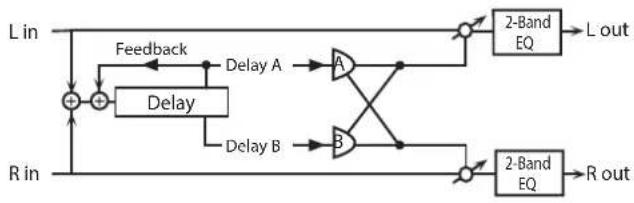
flowchart
graph TD
    L_in -->|Feedback| Delay_A["Delay A"]
    L_in -->|Feedback| Delay_B["Delay B"]
    Delay_A --> A["A"]
    Delay_B --> B["B"]
    A --> Out1["2-Band EQ"]
    B --> Out2["2-Band EQ"]
    Out1 --> L_out["L out"]
    Out2 --> R_out["R out"]
    R_in -->|Feedback| Delay_A
    R_in -->|Feedback| Delay_B
Parameter Value Explanation
| TIME # | 0-2600 msec, note | Adjusts the delay time from the direct sound until the delay sound is heard. |
| SHUFFLE RATE # | 0-100 | Adjusts the ratio (as a percentage) of the time that elapses before Delay B sounds relative to the time that elapses before the Delay A sounds.When set to 100, the delay times are the same. |
| ACCELERATION | 0-15 | Adjusts the speed which the Delay Time changes from the current setting to its specified new setting. |
| FEEDBACK # | -98-+98 % | Adjusts the amount of the delay that's fed back into the effect.Negative (-) settings invert the phase. |
| HF DAMP | 200-8000 Hz, BYPASS | Adjusts the frequency above which sound fed back to the effect is filtered out. If you don't want to filter out any high frequencies, set this parameter to BYPASS. |
| PAN A/B | L64-63R Stereo location of Delay A/B | |
| LEVEL A/B | 0-127 Volume of delay A/B | |
| EQ GAIN LOW | -15-+15 dB | Amount of boost/cut for the low-frequency range |
| EQ GAIN HIGH | -15-+15 dB | Amount of boost/cut for the high-frequency range |
| BALANCE # | D100:0W-D0:100W | Volume balance between the direct sound (D) and the effect sound (W) |
| OUTPUT LEVEL | 0-127 Output Level | |
52: 3D DELAY
This applies a 3D effect to the delay sound. The delay sound will be positioned 90 degrees left and 90 degrees right.

flowchart
graph TD
    L["Input L"] --> A["+"]
    R["Input R"] --> B["+"]
    A --> C["3D Delay L"]
    A --> D["3D Delay C"]
    A --> E["3D Delay R"]
    C --> F["Level"]
    D --> G["Feedback"]
    E --> H["+"]
    F --> I["2-Band EQ"]
    G --> J["2-Band EQ"]
    H --> K["2-Band EQ"]
    I --> L["L out"]
    J --> M["R out"]
| Parameter Value Explanation | ||
| TIME LEFT | Adjusts the delay time from the direct sound until the delay sound is heard. | |
| TIME CENTER | 0-2600 msec, note | |
| TIME RIGHT | ||
| CENTER FEEDBACK # | -98-+98 % | Adjusts the proportion of the delay sound that is fed back into the effect. Negative (-) settings will invert the phase. |
| HF DAMP | 200-8000 Hz, BYPASS | Adjusts the frequency above which sound fed back to the effect will be cut. If you do not want to cut the high frequencies, set this parameter to BYPASS. |
| LEVEL LEFT | ||
| LEVEL CENTER | 0-127 Output level of the delay sound | |
| LEVEL RIGHT | ||
| EQ GAIN LOW | -15-+15 dB | Amount of boost/cut for the low-frequency range |
| EQ GAIN HIGH | -15-+15 dB | Amount of boost/cut for the high-frequency range |
| BALANCE # | D100:0W-D0:100W | Volume balance between the direct sound (D) and the effect sound (W) |
| OUTPUT MODE | SPEAKER, PHONES | Adjusts the method that will be used to hear the sound that is output to the OUTPUT. The optimal 3D effect will be achieved if you select SPEAKER when using speakers, or PHONES when using headphones. |
| OUTPUT LEVEL | 0-127 Output Level | |
53: TIME CTRL DELAY
A stereo delay in which the delay time can be varied smoothly.

flowchart
graph LR
    A["L in"] --> B["+"]
    B --> C["Time Ctrl Delay"]
    C --> D["Pan L"]
    D --> E["2-Band EQ"]
    E --> F["L out"]
    G["R in"] --> H["+"]
    H --> I["Time Ctrl Delay"]
    I --> J["Pan R"]
    J --> K["2-Band EQ"]
    K --> L["R out"]
    B --> M["Feedback"]
    H --> N["Feedback"]
    D --> O["Pan L"]
    J --> P["Pan R"]
Parameter Value Explanation
| TIME # | 0-1300 msec, note | Adjusts the delay time from the direct sound until the delay sound is heard. |
| ACCELERATION | 0-15 | Adjusts the speed which the Delay Time changes from the current setting to a specified new setting.The rate of change for the Delay Time directly affects the rate of pitch change. |
| FEEDBACK # | -98-+98 % | Adjusts the amount of the delay that's fed back into the effect.Negative (-) settings invert the phase. |
| HF DAMP | 200-8000 Hz, BYPASS | Adjusts the frequency above which sound fed back to the effect is filtered out. If you do not want to filter out any high frequencies, set this parameter to BYPASS. |
| EQ GAIN LOW | -15-+15 dB | Amount of boost/cut for the low-frequency range |
| EQ GAIN HIGH | -15-+15 dB | Amount of boost/cut for the high-frequency range |
| BALANCE # | D100:0W-D0:100W | Volume balance between the direct sound (D) and the delay sound (W) |
| OUTPUT LEVEL | 0-127 Output Level |
54: LONG TIME CTRL DELAY
A delay in which the delay time can be varied smoothly, and allowing an extended delay to be produced.
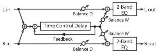
flowchart
graph TD
    A["L in"] --> B["+"]
    C["R in"] --> D["+"]
    B --> E["Time Control Delay"]
    D --> E
    E --> F["Balance D"]
    F --> G["+"]
    H["2-Band EQ"] --> I["L out"]
    J["2-Band EQ"] --> K["R out"]
    L["Balance W"] --> M["+"]
    N["Balance W"] --> O["+"]
    P["Feedback"] --> Q["+"]
    R["Balance D"] --> S["+"]
    T["Balance D"] --> U["+"]
    V["Balance W"] --> W["+"]
    X["Balance W"] --> Y["+"]
    Z["Balance W"] --> AA["+"]
    AB["Balance W"] --> AC["+"]
    AD["Balance W"] --> AE["+"]
    AF["Balance W"] --> AG["+"]
    AH["Balance W"] --> AI["+"]
    AJ["Balance W"] --> AK["+"]
    AL["Balance W"] --> AM["+"]
    AN["Balance W"] --> AO["+"]
    AP["Balance W"] --> AQ["+"]
    AR["Balance W"] --> AS["+"]
    AT["Balance W"] --> AU["+"]
    AV["Balance W"] --> AW["+"]
    AX["Balance W"] --> AY["+"]
    AZ["Balance W"] --> BA["+"]
    BB["Balance W"] --> BC["+"]
    BD["Balance W"] --> BE["+"]
    BF["Balance W"] --> BG["+"]
    BH["Balance W"] --> BI["+"]
    BJ["Balance W"] --> BK["+"]
    BL["Balance W"] --> BLA["+"]
    BM["Balance W"] --> BN["+"]
    BO["Balance W"] --> BP["+"]
    BQ["Balance D"] --> B
    RQ["Balance D"] --> D
Parameter Value Explanation
| TIME # | 0-2600 msec, note | Adjusts the delay time from the direct sound until the delay sound is heard. |
| ACCELERATION | 0-15 | Adjusts the speed which the Delay Time changes from the current setting to a specified new setting.The rate of change for the Delay Time directly affects the rate of pitch change. |
| FEEDBACK # | -98-+98 % | Adjusts the amount of the delay that's fed back into the effect.Negative (-) settings invert the phase. |
| HF DAMP | 200-8000 Hz, BYPASS | Adjusts the frequency above which sound fed back to the effect is filtered out. If you do not want to filter out any high frequencies, set this parameter to BYPASS. |
| PAN # | L64-63R Stereo location of the delay | |
| EQ GAIN LOW | -15-+15 dB | Amount of boost/cut for the low-frequency range |
| EQ GAIN HIGH | -15-+15 dB | Amount of boost/cut for the high-frequency range |
| BALANCE # | D100:0W-D0:100W | Volume balance between the direct sound (D) and the delay sound (W) |
| OUTPUT LEVEL | 0-127 Output Level | |
55: TAPE ECHO
A virtual tape echo that produces a realistic tape delay sound. This simulates the tape echo section of a Roland RE-201 Space Echo.

flowchart
graph LR
    L_in --> A["+"]
    R_in --> A
    A --> B["Tape Echo"]
    B --> C["+"]
    D["R out"] --> E["+"]
    F["L out"] --> G["+"]
    H["Echo Level"] --> I["+"]
    J["Echo Level"] --> K["+"]
    L_out --> G
    M["Direct Level"] --> N["+"]
    O["Direct Level"] --> P["+"]
Parameter Value Explanation
| MODE | S, M, L, S+M, S+L, M+L, S+M+L | Combination of playback heads to useSelect from three different heads with different delay times.S: shortM: middleL: long |
| REPEAT RATE # | 0-127 | Tape speedIncreasing this value will shorten the spacing of the delayed sounds. |
| INTENSITY # | 0-127 Amount of delay repeats | |
| BASS | -15-+15 dB | Boost/cut for the lower range of the echo sound |
| TREBLE | -15-+15 dB | Boost/cut for the upper range of the echo sound |
| HEAD PAN S | L64-63R | Independent panning for the short, middle, and long playback heads |
| HEAD PAN M | ||
| HEAD PAN L | ||
| DISTORTION | 0-5 | Amount of tape-dependent distortion to be addedThis simulates the slight tonal changes that can be detected by signal-analysis equipment.Increasing this value will increase the distortion. |
| WOW/FLUTTER RATE | 0-127 | Speed of wow/flutter (complex variation in pitch caused by tape wear and rotational irregularity) |
| WOW/FLUTTER DEPTH | 0-127 Depth of wow/flutter | |
| ECHO LEVEL # | 0-127 Volume of the echo sound | |
| DIRECT LEVEL # | 0-127 Volume of the original sound | |
| OUTPUT LEVEL | 0-127 Output level | |
56: LOFI NOISE
In addition to a lo-fi effect, this adds various types of noise such as white noise and disc noise.

flowchart
graph LR
    L_in --> A["Lo-Fi"]
    A --> B["+"]
    B --> C["2-Band EQ"]
    C --> D["L out"]
    R_in --> E["Lo-Fi"]
    E --> F["+"]
    F --> G["2-Band EQ"]
    G --> H["R out"]
    I["Noise Gen."] --> F
Parameter Value Explanation
| LOFI TYPE | 1-9 | Degrades the sound quality. The sound quality grows poorer as this value is increased. |
| POST FILTER TYPE | OFF, LPF, HPF | Type of filter that follows the LoFi effectOFF: no filter is usedLPF: cuts the frequency range above the CutoffHPF: cuts the frequency range below the Cutoff |
| POST FILTER CUTOFF | 200-8000 Hz Center frequency of the filter | |
| W/P NOISE TYPE | WHITE, PINK | Switch between white noise and pink noise. |
| W/P NOISE LPF | 200-8000 Hz, BYPASS | Center frequency of the low pass filter applied to the white/pink noise (BYPASS: no cut) |
| W/P NOISE LEVEL # | 0-127 Volume of the white/pink noise | |
| DISC NOISE TYPE | LP, EP, SP, RND | Type of record noiseThe frequency at which the noise is heard depends on the selected type. |
| DISC NOISE LPF | 200-8000 Hz, BYPASS | Adjusts the cutoff frequency of the low pass filter applied to the record noise. If you don't want to filter out any high frequencies, set this parameter to BYPASS. |
| DISC NOISE LEVEL # | 0-127 Volume of the record noise | |
| HUM TYPE | 50Hz, 60Hz Frequency of the hum noise | |
| HUM LPF | 200-8000 Hz, BYPASS | Center frequency of the low pass filter applied to the hum noise (BYPASS: no cut) |
| HUM LEVEL # | 0-127 Volume of the hum noise | |
| EQ GAIN LOW | -15-+15 dB | Amount of boost/cut for the low-frequency range |
| EQ GAIN HIGH | -15-+15 dB | Amount of boost/cut for the high-frequency range |
| BALANCE # | D100:0W-D0:100W | Volume balance between the direct sound (D) and the effect sound (W) |
| OUTPUT LEVEL | 0-127 Output Level | |
57: LOFI COMPRESS
This is an effect that intentionally degrades the sound quality for creative purposes.

flowchart
graph LR
    A["L in"] --> B["Compressor"]
    B --> C["Lo-Fi"]
    C --> D["2-Band EQ"]
    D --> E["L out"]
    F["R in"] --> G["Compressor"]
    G --> H["Lo-Fi"]
    H --> I["2-Band EQ"]
    I --> J["R out"]
Parameter Value Explanation
| LOFI TYPE | 1-9 | Degrades the sound quality. The sound quality grows poorer as this value is increased. |
| PRE FILTER TYPE | 1-6 | Selects the type of filter applied to the sound before it passes through the Lo-Fi effect.1: Compressor off2-6: Compressor on |
| POST FILTER TYPE | OFF, LPF, HPF | Type of filterOFF: no filter is usedLPF: cuts the frequency range above the CutoffHPF: cuts the frequency range below the Cutoff |
| POST FILTER CUTOFF | 200-8000 Hz Basic frequency of the Post Filter | |
| EQ GAIN LOW | -15-+15 dB | Amount of boost/cut for the low-frequency range |
| EQ GAIN HIGH | -15-+15 dB | Amount of boost/cut for the high-frequency range |
| BALANCE # | D100;0W-D0:100W | Volume balance between the direct sound (D) and the effect sound (W) |
| OUTPUT LEVEL # | 0-127 Output Level | |
58: LOFI RADIO
In addition to a Lo-Fi effect, this effect also generates radio noise.
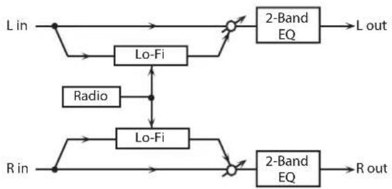
flowchart
graph TD
    A["L in"] --> B["Lo-Fi"]
    B --> C["2-Band EQ"]
    C --> D["L out"]
    E["Radio"] --> F["Lo-Fi"]
    F --> G["2-Band EQ"]
    G --> H["R out"]
    I["R in"] --> J["Lo-Fi"]
    J --> K["2-Band EQ"]
    K --> L["R out"]
    B --> M["+"]
    F --> N["-"]
    J --> O["-"]
Parameter Value Explanation
| LOFI TYPE | 1-9 | Degrades the sound quality. The sound quality grows poorer as this value is increased. |
| POST FILTER TYPE | OFF, LPF, HPF | Type of filterOFF: no filter is usedLPF: cuts the frequency range above the CutoffHPF: cuts the frequency range below the Cutoff |
| POST FILTER CUTOFF | 200-8000 Hz Basic frequency of the Post Filter | |
| RADIO NOISE DETUNE # | 0-127 | Simulates the tuning noise of a radio. As this value is raised, the tuning drifts further. |
| RADIO NOISE LEVEL # | 0-127 Volume of the radio noise | |
| EQ GAIN LOW | -15-+15 dB | Amount of boost/cut for the low-frequency range |
| EQ GAIN HIGH | -15-+15 dB | Amount of boost/cut for the high-frequency range |
| BALANCE # | D100:0W-D0:100W | Volume balance between the direct sound (D) and the effect sound (W) |
| OUTPUT LEVEL | 0-127 Output Level | |
59: TELEPHONE
This effect produces a muffled sound, like that heard through a telephone.
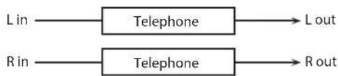
flowchart
graph LR
    A["Lin"] --> B["Telephone"]
    C["Rin"] --> D["Telephone"]
    B --> E["Lout"]
    D --> F["Rout"]
Parameter Value Explanation
| VOICE QUALITY # | 0-15 Audio quality of the telephone voice | |
| TREBLE | -15-+15 dB | Amount of boost/cut for the high frequency range |
| BALANCE # | D100:0W-D0:100W | Volume balance between the direct sound (D) and the effect sound (W) |
| OUTPUT LEVEL | 0-127 Output Level | |
60: PHONOGRAPH
Simulates a sound recorded on an analog record and played back on a record player. This effect also simulates the various types of noise that are typical of a record, and even the rotational irregularities of an old turntable.

flowchart
graph LR
    L_in --> A["Phonograph"]
    A --> B["Balance D"]
    B --> C["L out"]
    R_in --> D["Phonograph"]
    D --> E["Balance W"]
    E --> F["R out"]
    A --> G["Balance W"]
    G --> H["Balance W"]
    H --> I["Balance D"]
    I --> J["Balance D"]
Parameter Value Explanation
| SIGNAL DISTORTION | 0-127 Degree of distortion | |
| FREQUENCY RANGE | 0-127 | Frequency response of the playback systemDecreasing this value will produce the impression of an old system with a poor frequency response. |
| DISC TYPE | LP, EP, SP | Rotational speed of the turntableThis will affect the cycle of the scratch noise. |
| NOISE LEVEL SCRATCH | 0-127 | Amount of noise due to scratches on the record |
| NOISE LEVEL DUST | 0-127 | Volume of noise due to dust on the record |
| NOISE LEVEL HISS | 0-127 Volume of continuous hiss | |
| NOISE LEVEL TOTAL | 0-127 Volume of overall noise | |
| WOW | 0-127 | Depth of long-cycle rotational irregularity |
| FLUTTER | 0-127 | Depth of short-cycle rotational irregularity |
| WOW/FLUTTER RANDOM | 0-127 | Depth of indefinite-cycle rotational irregularity |
| WOW/FLUTTER TOTAL # | 0-127 | Depth of overall rotational irregularity |
| BALANCE # | D100:0W-D0:100W | Volume balance between the direct sound (D) and the effect sound (W) |
| OUTPUT LEVEL | 0-127 Output Level | |
61: PITCH SHIFTER
A stereo pitch shifter.
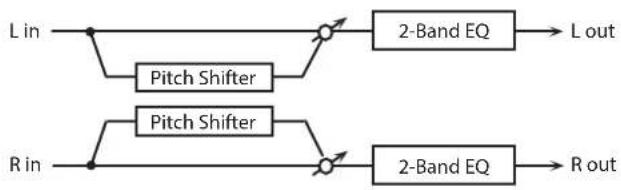
flowchart
graph LR
    A["L in"] --> B["Pitch Shifter"]
    B --> C["2-Band EQ"]
    C --> D["L out"]
    E["R in"] --> F["Pitch Shifter"]
    F --> G["2-Band EQ"]
    G --> H["R out"]
Parameter Value Explanation
| COARSE #1 | -24-+12 semi | Adjusts the pitch of the pitch shifted sound in semitone steps. |
| FINE #1 | -100-+100 cent | Adjusts the pitch of the pitch shifted sound in 2-cent steps. |
| DELAY TIME | 0-1300 msec, note | Adjusts the delay time from the direct sound until the pitch shifted sound is heard. |
| FEEDBACK # | -98-+98 % | Adjusts the proportion of the pitch shifted sound that is fed back into the effect. Negative (-) settings will invert the phase. |
| EQ GAIN LOW | -15-+15 dB | Amount of boost/cut for the low-frequency range |
| EQ GAIN HIGH | -15-+15 dB | Amount of boost/cut for the high-frequency range |
| BALANCE # | D100:0W-D0:100W | Volume balance between the direct sound (D) and the pitch shifted sound (W) |
| OUTPUT LEVEL | 0-127 Output Level |
62: 2VOICE PITCH SHIFTER
Shifts the pitch of the original sound. This 2-voice pitch shifter has two pitch shifters, and can add two pitch shifted sounds to the original sound.

flowchart
graph TD
    A["L in"] --> B["+"]
    C["R in"] --> D["Level 1"]
    B --> E["Level 1"]
    D --> F["Level 1"]
    E --> G["Pan 1 L"]
    F --> H["Pan 2 R"]
    G --> I["Balance D"]
    H --> J["Balance W"]
    I --> K["Balance D"]
    J --> L["Balance W"]
    K --> M["Balance D"]
    L --> N["L out"]
    M --> O["R out"]
    P["2Voice Pitch Shifter"] --> Q["Pan 1 R"]
    P --> R["Pan 2 L"]
    Q --> S["Balance D"]
    R --> T["Balance W"]
Parameter Value Explanation
| PITCH1 COARSE #1 | -24–+12 semi | Adjusts the pitch of Pitch Shift 1 in semitone steps. |
| PITCH1 FINE #1 | -100–+100 cent | Adjusts the pitch of Pitch Shift Pitch 1 in 2-cent steps. |
| PITCH1 DELAY | 0–1300 msec, note | Adjusts the delay time from the direct sound until the Pitch Shift 1 sound is heard. |
| PITCH1 FEEDBACK # | -98–+98 % | Adjusts the proportion of the pitch shifted sound that is fed back into the effect. Negative (-) settings will invert the phase. |
| PITCH1 LEVEL | 0–127 Volume of the Pitch Shift 1 sound | |
| PITCH1 PAN # | L64–63R | Stereo location of the Pitch Shift 1 sound |
| PITCH2 COARSE #2 | 24–+12 semi | Settings of the Pitch Shift 2 sound.The parameters are the same as for the Pitch Shift 1 sound. |
| PITCH2 FINE #2 | -100–+100 cent | |
| PITCH2 DELAY | 0–1300 msec, note | |
| PITCH2 FEEDBACK # | -98–+98 % | |
| PITCH2 LEVEL | 0–127 | |
| PITCH2 PAN # | L64–63R | |
| EQ GAIN LOW | -15–+15 dB | Amount of boost/cut for the low-frequency range |
| EQ GAIN HIGH | -15–+15 dB | Amount of boost/cut for the high-frequency range |
| BALANCE # | D100:0W–D0:100W | Volume balance between the direct sound (D) and the pitch shifted sound (W) |
| OUTPUT LEVEL | 0–127 Output Level | |
63: STEP PITCH SHIFTER
A pitch shifter in which the amount of pitch shift is varied by a 16-step sequence.

flowchart
graph LR
    A["L in"] --> B["Step Pitch Shifter"]
    B --> C["2-Band EQ"]
    C --> D["L out"]
    E["R in"] --> F["Step Pitch Shifter"]
    F --> G["2-Band EQ"]
    G --> H["R out"]
Parameter Value Explanation
| RATE # | 0.05–10.0 Hz, note | Rate at which the 16-step sequence will cycle |
| ATTACK # | 0–127 | Speed at which the amount of pitch shift changes between steps |
| GATE TIME # | 0–127 | Duration of the pitch shifted sound at each step |
| FINE | -100–+100 cent | Pitch shift adjustment for all steps (2-cent units) |
| DELAY TIME | 0–1300 msec, note | Adjusts the delay time from the direct sound until the pitch shifted sound is heard. |
| FEEDBACK # | -98–+98 % | Proportion of the pitch-shifted sound that is to be returned to the input (negative values invert the phase) |
| STEP 1–16 | -24–+12 semi | Amount of pitch shift at each step (semitone units) |
| EQ GAIN LOW | -15–+15 dB | Amount of boost/cut for the low-frequency range |
| EQ GAIN HIGH | -15–+15 dB | Amount of boost/cut for the high-frequency range |
| BALANCE # | D100:0W–D0:100W | Volume balance of the original sound (D) and pitch-shifted sound (W) |
| OUTPUT LEVEL | 0–127 Output Level |
MEMO
You can use multi-effect control to make the step sequence play again from the beginning (p. 38).
64: REVERB
Adds reverberation to the sound, simulating an acoustic space.

flowchart
graph LR
    L_in --> A["+"]
    R_in --> B["+"]
    A --> C["Balance D"]
    B --> D["Balance D"]
    C --> E["+"]
    D --> F["+"]
    E --> G["Balance W"]
    F --> H["Balance W"]
    G --> I["2-Band EQ"]
    H --> J["2-Band EQ"]
    I --> K["L out"]
    J --> L["R out"]
Parameter Value Explanation
| TYPE | ROOM1, ROOM2, STAGE1, STAGE2, HALL1, HALL2 | Type of reverbROOM1: dense reverb with short decayROOM2: sparse reverb with short decaySTAGE1: reverb with greater late reverberationSTAGE2: reverb with strong early reflectionsHALL1: reverb with clear reverberanceHALL2: reverb with rich reverberance |
| PRE DELAY | 0.0–100 msec | Adjusts the delay time from the direct sound until the reverb sound is heard. |
| TIME # | 0–127 Time length of reverberation | |
| HF DAMP | 200–8000 Hz, BYPASS | Adjusts the frequency above which the reverberant sound will be cut.As the frequency is set lower, more of the high frequencies will be cut, resulting in a softer and more muted reverberance.If you do not want to cut the high frequencies, set this parameter to BYPASS. |
| EQ GAIN LOW | -15–+15 dB | Amount of boost/cut for the low-frequency range |
| EQ GAIN HIGH | -15–+15 dB | Amount of boost/cut for the high-frequency range |
| BALANCE # | D100:0W–D0:100W | Volume balance between the direct sound (D) and the reverb sound (W) |
| OUTPUT LEVEL | 0–127 Output Level | |
65: GATED REVERB
This is a special type of reverb in which the reverberant sound is cut off before its natural length.

flowchart
graph LR
    L_in --> GatedReverb
    R_in --> GatedReverb
    GatedReverb --> BalanceD1["Balance D"]
    GatedReverb --> BalanceW1["Balance W"]
    GatedReverb --> BalanceW2["Balance W"]
    BalanceD1 --> GatedReverb
    BalanceW1 --> GatedReverb
    BalanceW2 --> GatedReverb
    GatedReverb --> 2BandEQ1["2-Band EQ"]
    GatedReverb --> 2BandEQ2["2-Band EQ"]
    2BandEQ1 --> Lout["L out"]
    2BandEQ2 --> Rout["R out"]
Parameter Value Explanation
| TYPE | NORMAL, REVERSE, SWEEP1, SWEEP2 | Type of reverbNORMAL: conventional gated reverbREVERSE: backwards reverbSWEEP1: the reverberant sound moves from right to leftSWEEP2: the reverberant sound moves from left to right |
| PRE DELAY | 0.0–100 msec | Adjusts the delay time from the direct sound until the reverb sound is heard. |
| GATE TIME | 5–500 msec Time length of reverberation | |
| EQ GAIN LOW | -15–+15 dB | Amount of boost/cut for the low-frequency range |
| EQ GAIN HIGH | -15–+15 dB | Amount of boost/cut for the high-frequency range |
| BALANCE # | D100:0W–D0:100W | Volume balance between the direct sound (D) and the reverb sound (W) |
| OUTPUT LEVEL # | 0–127 Output Level | |
66: OVERDRIVE → CHORUS

flowchart
graph LR
    A["L in"] --> B["+"]
    C["R in"] --> B
    B --> D["Overdrive"]
    D --> E["Chorus"]
    E --> F["Balance D"]
    E --> G["Balance W"]
    E --> H["Balance W"]
    E --> I["Balance D"]
    E --> J["Balance W"]
    E --> K["R out"]
    F --> L["L out"]
    G --> M["R out"]
Parameter Value Explanation
| OVERDRIVE DRIVE # | 0-127 | Degree of distortionAlso changes the volume. |
| OVERDRIVE PAN # | L64-63R | Stereo location of the overdrive sound |
| CHORUS RATE # | 0.05-10.00 Hz, note Frequency of modulation | |
| CHORUS DEPTH | 0-127 Depth of modulation | |
| CHORUS PRE DELAY | 0.0-100 msec | Adjusts the delay time from the direct sound until the chorus sound is heard. |
| CHORUS BALANCE # | D100:0W-D0:100W | Adjusts the volume balance between the sound that is sent through the chorus (W) and the sound that is not sent through the chorus (D). |
| OUTPUT LEVEL | 0-127 Output Level | |
67: OVERDRIVE → FLANGER

flowchart
graph TD
    A["L in"] --> B["+"]
    C["R in"] --> B
    B --> D["Overdrive"]
    D --> E["+"]
    F["Balance D"] --> G["+"]
    H["Balance W"] --> I["+"]
    J["Balance W"] --> K["+"]
    L["Balance D"] --> M["+"]
    N["Balance D"] --> O["+"]
    P["Feedback"] --> E
    Q["R out"] --> M
    R["L out"] --> G
    S["R out"] --> O
Parameter Value Explanation
| OVERDRIVE DRIVE # | 0-127 | Degree of distortionAlso changes the volume. |
| OVERDRIVE PAN # | L64-63R | Stereo location of the overdrive sound |
| FLANGER RATE # | 0.05-10.00 Hz, note Frequency of modulation | |
| FLANGER DEPTH | 0-127 Depth of modulation | |
| FLANGER FEEDBACK # | -98-+98 % | Adjusts the proportion of the flanger sound that is fed back into the effect. Negative (-) settings will invert the phase. |
| FLANGER PRE DELAY | 0.0-100 msec | Adjusts the delay time from when the direct sound begins until the flanger sound is heard. |
| FLANGER BALANCE # | D100:0W-D0:100W | Adjusts the volume balance between the sound that is sent through the flanger (W) and the sound that is not sent through the flanger (D). |
| OUTPUT LEVEL | 0-127 Output Level | |
68: OVERDRIVE → DELAY
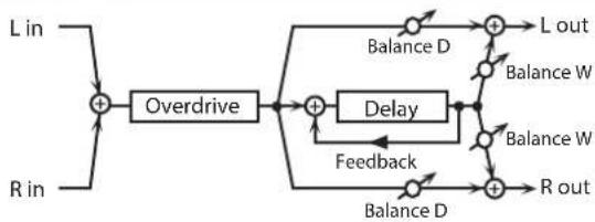
flowchart
graph TD
    A["L in"] --> B["+"]
    C["R in"] --> B
    B --> D["Overdrive"]
    D --> E["+"]
    F["Balance D"] --> G["+"]
    H["Balance W"] --> I["+"]
    J["Balance W"] --> K["+"]
    L["Balance D"] --> M["+"]
    N["Balance D"] --> O["+"]
    P["Feedback"] --> Q["Delay"]
    Q --> R["+"]
    S["R out"] --> T["+"]
    U["L out"] --> V["+"]
Parameter Value Explanation
| OVERDRIVE DRIVE # | 0-127 | Degree of distortionAlso changes the volume. |
| OVERDRIVE PAN # | L64-63R | Stereo location of the overdrive sound |
| DELAY TIME | 0-2600 msec, note | Adjusts the delay time from the direct sound until the delay sound is heard. |
| DELAY FEEDBACK # | 98-+98 % | Adjusts the proportion of the delay sound that is fed back into the effect. Negative (-) settings will invert the phase. |
| DELAY HF DAMP | 200-8000 Hz, BYPASS | Adjusts the frequency above which sound fed back to the effect will be cut. If you do not want to cut the high frequencies, set this parameter to BYPASS. |
| DELAY BALANCE # | D100:0W-D0:100W | Adjusts the volume balance between the sound that is sent through the delay (W) and the sound that is not sent through the delay (D). |
| OUTPUT LEVEL | 0-127 Output Level | |
69: DISTORTION → CHORUS
The parameters are essentially the same as in "66: OVERDRIVE → CHORUS," with the exception of the following two.
Overdrive Drive → Distortion Drive,
Overdrive Pan → Distortion Pan

flowchart
graph LR
    A["L in"] --> B["+"]
    C["R in"] --> B
    B --> D["Distortion"]
    D --> E["Chorus"]
    E --> F["Balance D"]
    E --> G["Balance W"]
    E --> H["Balance W"]
    E --> I["Balance D"]
    E --> J["R out"]
    F --> K["L out"]
    G --> K
    H --> K
    I --> K
    J --> K
70: DISTORTION → FLANGER
The parameters are essentially the same as in "67: OVERDRIVE → FLANGER," with the exception of the following two.
Overdrive Drive → Distortion Drive,
Overdrive Pan → Distortion Pan

flowchart
graph TD
    A["L in"] --> B["+"]
    C["R in"] --> B
    B --> D["Distortion"]
    D --> E["+"]
    F["Balance D"] --> G["+"]
    H["Balance W"] --> I["+"]
    J["Balance D"] --> K["+"]
    L["R out"] --> M["+"]
    N["Feedback"] --> O["Flanger"]
    O --> P["+"]
    Q["Balance W"] --> R["+"]
    S["Balance D"] --> T["+"]
    U["Balance W"] --> V["+"]
    W["Balance D"] --> X["+"]
    Y["Balance W"] --> Z["+"]
    AA["Balance D"] --> AB["+"]
    AC["Balance W"] --> AD["+"]
    AE["Balance D"] --> AF["+"]
    AG["Balance W"] --> AH["+"]
    AI["Balance D"] --> AJ["+"]
    AK["Balance W"] --> AL["+"]
    AM["Balance D"] --> AN["+"]
    AO["Balance W"] --> AP["+"]
    AQ["Balance D"] --> AR["+"]
    AS["L out"] --> AT["+"]
    AU["R out"] --> AV["+"]
71: DISTORTION → DELAY
The parameters are essentially the same as in "68: OVERDRIVE → DELAY," with the exception of the following two.
Overdrive Drive → Distortion Drive,
Overdrive Pan → Distortion Pan

flowchart
graph TD
    A["L in"] --> B["+"]
    C["R in"] --> B
    B --> D["Distortion"]
    D --> E["+"]
    F["Balance D"] --> G["+"]
    H["Balance W"] --> I["+"]
    J["Balance W"] --> K["+"]
    L["Balance D"] --> M["+"]
    N["Balance D"] --> O["+"]
    P["Feedback"] --> Q["+"]
    R["R out"] --> S["+"]
    T["L out"] --> G
    U["Feedback"] --> V["+"]
72: ENHANCER → CHORUS

flowchart
graph LR
    A["L in"] --> B["Enhancer"]
    B --> C["Mix"]
    C --> D["+"]
    D --> E["Balance D"]
    E --> F["L out"]
    G["R in"] --> H["Enhancer"]
    H --> I["Mix"]
    I --> J["+"]
    J --> K["Balance D"]
    K --> L["R out"]
    D --> M["Chorus"]
    M --> N["Balance W"]
    N --> O["+"]
    O --> P["Balance D"]
    P --> Q["+"]
    Q --> R["Balance W"]
    R --> S["+"]
    S --> T["Balance W"]
Parameter Value Explanation
| ENHANCER SENS # | 0-127 Sensitivity of the enhancer | |
| ENHANCER MIX # | 0-127 | Level of the overtones generated by the enhancer |
| CHORUS RATE # | 0.05-10.00 Hz, note Frequency of modulation | |
| CHORUS DEPTH | 0-127 Depth of modulation | |
| CHORUS PRE DELAY | 0.0-100 msec | Adjusts the delay time from the direct sound until the chorus sound is heard. |
| CHORUS BALANCE # | D100:0W-D0:100W | Adjusts the volume balance between the sound that is sent through the chorus (W) and the sound that is not sent through the chorus (D). |
| OUTPUT LEVEL | 0-127 Output Level | |
73: ENHANCER → FLANGER
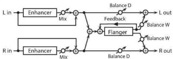
flowchart
graph LR
    A["L in"] --> B["Enhancer"]
    B --> C["Mix"]
    C --> D["+"]
    D --> E["Balance D"]
    E --> F["L out"]
    G["R in"] --> H["Enhancer"]
    H --> I["Mix"]
    I --> J["+"]
    J --> K["Balance D"]
    K --> L["R out"]
    M["Feedback"] --> N["Flanger"]
    N --> O["Balance W"]
    O --> F
    P["Balance W"] --> N
    Q["Balance W"] --> N
Parameter Value Explanation
| ENHANCER SENS # | 0-127 Sensitivity of the enhancer | |
| ENHANCER MIX # | 0-127 | Level of the overtones generated by the enhancer |
| FLANGER RATE # | 0.05-10.00 Hz, note Frequency of modulation | |
| FLANGER DEPTH | 0-127 Depth of modulation | |
| FLANGER FEEDBACK # | -98-+98 % | Adjusts the proportion of the flanger sound that is fed back into the effect. Negative (-) settings will invert the phase. |
| FLANGER PRE DELAY | 0.0-100 msec | Adjusts the delay time from when the direct sound begins until the flanger sound is heard. |
| FLANGER BALANCE # | D100:0W-D0:100W | Adjusts the volume balance between the sound that is sent through the flanger (W) and the sound that is not sent through the flanger (D). |
| OUTPUT LEVEL | 0-127 Output Level | |
74: ENHANCER → DELAY
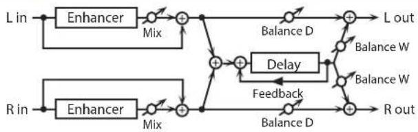
flowchart
graph LR
    L_in --> Enhancer1["Enhancer"]
    R_in --> Enhancer2["Enhancer"]
    L_in --> Mix1["Mix"]
    R_in --> Mix2["Mix"]
    Mix1 --> Add1["+"]
    Mix2 --> Add2["+"]
    Add1 --> BalanceD1["Balance D"]
    Add2 --> Delay["Delay"]
    Delay --> Feedback["Feedback"]
    BalanceD1 --> Add3["+"]
    Delay --> Add4["+"]
    Add3 --> Lout["L out"]
    Add4 --> Rout["R out"]
    Lout --> BalanceW1["Balance W"]
    Rout --> BalanceW2["Balance W"]
Parameter Value Explanation
| ENHANCER SENS # | 0-127 Sensitivity of the enhancer | |
| ENHANCER MIX # | 0-127 | Level of the overtones generated by the enhancer |
| DELAY TIME | 0-2600 msec, note | Adjusts the delay time from the direct sound until the delay sound is heard. |
| DELAY FEEDBACK # | -98-+98 % | Adjusts the proportion of the delay sound that is fed back into the effect. Negative (-) settings will invert the phase. |
| DELAY HF DAMP | 200-8000 Hz, BYPASS | Adjusts the frequency above which sound fed back to the effect will be cut. If you do not want to cut the high frequencies, set this parameter to BYPASS. |
| DELAY BALANCE # | D100:0W-D0:100W | Adjusts the volume balance between the sound that is sent through the delay (W) and the sound that is not sent through the delay (D). |
| OUTPUT LEVEL | 0-127 Output Level | |
75: CHORUS → DELAY

flowchart
graph LR
    L_in --> A["+"]
    R_in --> B["+"]
    A --> C["Balance D"]
    B --> D["Balance D"]
    C --> E["Chorus"]
    D --> F["Chorus"]
    E --> G["+"]
    F --> H["+"]
    G --> I["+"]
    H --> J["+"]
    I --> K["Balance D"]
    J --> L["Balance D"]
    K --> M["Balance D"]
    L --> N["L out"]
    M --> O["L out"]
    N --> P["Feedback"]
    O --> Q["Feedback"]
    P --> R["R out"]
    Q --> S["R out"]
Parameter Value Explanation
| CHORUS RATE # | 0.05–10.00 Hz, note Frequency of modulation | |
| CHORUS DEPTH | 0–127 Depth of modulation | |
| CHORUS PRE DELAY | 0.0–100 msec | Adjusts the delay time from the direct sound until the chorus sound is heard. |
| CHORUS BALANCE # | D100:0W–D0:100W | Volume balance between the direct sound (D) and the chorus sound (W) |
| DELAY TIME | 0–2600 msec, note | Adjusts the delay time from the direct sound until the delay sound is heard. |
| DELAY FEEDBACK # | -98–+98 % | Adjusts the proportion of the delay sound that is fed back into the effect. Negative (-) settings will invert the phase. |
| DELAY HF DAMP | 200–8000 Hz, BYPASS | Adjusts the frequency above which sound fed back to the effect will be cut. If you do not want to cut the high frequencies, set this parameter to BYPASS. |
| DELAY BALANCE # | D100:0W–D0:100W | Adjusts the volume balance between the sound that is sent through the delay (W) and the sound that is not sent through the delay (D). |
| OUTPUT LEVEL | 0–127 Output Level | |
76: FLANGER → DELAY

flowchart
graph LR
    L_in --> A["+"]
    R_in --> B["+"]
    A --> C["Balance D"]
    B --> D["Balance D"]
    C --> E["+"]
    D --> F["+"]
    E --> G["Feedback"]
    F --> H["Feedback"]
    G --> I["Flanger"]
    H --> J["Delay"]
    I --> K["Balance W"]
    J --> L["Balance W"]
    K --> M["Balance D"]
    L --> N["Balance D"]
    M --> O["+"]
    N --> P["+"]
    O --> Q["L out"]
    P --> R["R out"]
Parameter Value Explanation
| FLANGER RATE # | 0.05–10.00 Hz, note Frequency of modulation | |
| FLANGER DEPTH | 0–127 Depth of modulation | |
| FLANGER FEEDBACK # | -98–+98 % | Adjusts the proportion of the flanger sound that is fed back into the effect. Negative (-) settings will invert the phase. |
| FLANGER PRE DELAY | 0.0–100 msec | Adjusts the delay time from when the direct sound begins until the flanger sound is heard. |
| FLANGER BALANCE # | D100:0W–D0:100W | Volume balance between the direct sound (D) and the flanger sound (W) |
| DELAY TIME | 0–2600 msec, note | Adjusts the delay time from the direct sound until the delay sound is heard. |
| DELAY FEEDBACK # | -98–+98 % | Adjusts the proportion of the delay sound that is fed back into the effect. Negative (-) settings will invert the phase. |
| DELAY HF DAMP | 200–8000 Hz, BYPASS | Adjusts the frequency above which sound fed back to the effect will be cut. If you do not want to cut the high frequencies, set this parameter to BYPASS. |
| DELAY BALANCE # | D100:0W–D0:100W | Adjusts the volume balance between the sound that is sent through the delay (W) and the sound that is not sent through the delay (D). |
| OUTPUT LEVEL | 0–127 Output Level | |
77: CHORUS → FLANGER

flowchart
graph LR
    L_in --> A["+"]
    R_in --> B["+"]
    A --> C["Balance D"]
    B --> D["Balance D"]
    C --> E["Chorus"]
    D --> E
    E --> F["+"]
    G["Feedback"] --> H["Flanger"]
    I["Balance W"] --> H
    H --> J["+"]
    K["Balance W"] --> J
    J --> L_out["L out"]
    M["Balance W"] --> J
    J --> N_Rout["R out"]
Parameter Value Explanation
| CHORUS RATE # | 0.05–10.00 Hz, note | Modulation frequency of the chorus effect |
| CHORUS DEPTH | 0–127 | Modulation depth of the chorus effect |
| CHORUS PRE DELAY | 0.0–100 msec | Adjusts the delay time from the direct sound until the chorus sound is heard. |
| CHORUS BALANCE # | D100:0W–D0:100W | Volume balance between the direct sound (D) and the chorus sound (W) |
| FLANGER RATE # | 0.05–10.00 Hz, note | Modulation frequency of the flanger effect |
| FLANGER DEPTH | 0–127 | Modulation depth of the flanger effect |
| FLANGER FEEDBACK # | -98–+98 % | Adjusts the proportion of the flanger sound that is fed back into the effect. Negative (-) settings will invert the phase. |
| FLANGER PRE DELAY | 0.0–100 msec | Adjusts the delay time from when the direct sound begins until the flanger sound is heard. |
| FLANGER BALANCE # | D100:0W–D0:100W | Adjusts the volume balance between the sound that is sent through the flanger (W) and the sound that is not sent through the flanger (D). |
| OUTPUT LEVEL | 0–127 Output Level |
78: SYMPATHETIC RESONANCE
On an acoustic piano, holding down the damper pedal allows other strings to resonate in sympathy with the notes you play, creating rich and spacious resonances. This effect simulates these sympathetic resonances.

flowchart
graph LR
    L_in --> A["Sym. Resonance"]
    R_in --> A
    A --> B["+"]
    B --> C["3-Band EQ"]
    C --> D["L out"]
    A --> E["+"]
    E --> F["3-Band EQ"]
    F --> G["R out"]
Parameter Value Explanation
| RESONANCE DEPTH # | 0-127 Depth of the effect | |
| RESONANCE DAMPER # | 0-127 | Depth to which the damper pedal is pressed (controls the resonant sound) |
| RESONANCE PRE LPF | 16-15000 Hz, BYPASS | Frequency of the filter that cuts the high-frequency content of the input sound (BYPASS: no cut) |
| RESONANCE PRE HPF | BYPASS, 16-15000 Hz | Frequency of the filter that cuts the low-frequency content of the input sound (BYPASS: no cut) |
| RESONANCE PEAKING FREQ | 200-8000 Hz | Frequency of the filter that boosts/ cuts a specific frequency region of the input sound |
| RESONANCE PEAKING Q | 0.5, 1.0, 2.0, 4.0, 8.0 | Width of the frequency region boosted/cut by the 'Peaking Gain' parameter (larger values make the region narrower) |
| RESONANCE PEAKING GAIN | -15-+15 dB | Amount of boost/cut produced by the filter at the specified frequency region of the input sound |
| RESONANCE HF DAMP | 16-15000 Hz, BYPASS | Frequency at which the high- frequency content of the resonant sound will be cut (BYPASS: no cut) |
| RESONANCE LF DAMP | BYPASS, 16-15000 Hz | Frequency at which the low- frequency content of the resonant sound will be cut (BYPASS: no cut) |
| RESONANCE LID | 1-6 | This simulates the actual changes in sound that occur when the lid of a grand piano is set at different heights. |
| LOW FREQ | 200, 400 Hz | Frequency of the low-range of the EQ |
| LOW GAIN | -15-+15 dB | Amount of boost/cut for the low- range of the EQ |
| MID FREQ | 200-8000 Hz | Frequency of the mid-range of the EQ |
| MID GAIN | -15-+15 dB | Amount of mid-range of the EQ boost/cut |
| MID Q | 0.5, 1.0, 2.0, 4.0, 8.0 | Width of mid-range of the EQ (larger values make the region narrower) |
| HIGH FREQ | 2000, 4000, 8000 Hz | Frequency of the high-range of the EQ |
| HIGH GAIN | -15-+15 dB | Amount of boost/cut for the high- range of the EQ |
| OUTPUT LEVEL | 0-127 Output Level | |
Chorus Parameters
The SRX ORCHESTRA's Chorus effect unit can also be used as a stereo delay unit. These settings allow you to select chorus or delay, and the characteristics of the selected effect type.
Parameter Value Explanation
| CHORUS | ||
| RATE | 0.05–10.00 Hz, note | Modulation frequency of the chorus effect |
| DEPTH | 0–127 | Modulation depth of the chorus effect |
| PRE DELAY | 0.0–100 msec | Adjusts the delay time from the direct sound until the chorus sound is heard. |
| FEEDBACK | 0–127 | Adjusts the amount of the chorus sound that is fed back into the effect. |
| FILTER TYPE | OFF, LPF, HPF | Type of filterOFF: no filter is usedLPF: cuts the frequency range above the Cutoff FreqHPF: cuts the frequency range below the Cutoff Freq |
| CUTOFF | 200–8000 Hz Basic frequency of the filter | |
| PHASE | 0–180 deg Spatial spread of the sound | |
DELAY
| DELAY TIME LEFT | 0-1000 msec, note | Adjusts the delay time from the direct sound until the delay sound is heard. |
| DELAY TIME CENTER | ||
| DELAY TIME RIGHT | ||
| CENTER FEEDBACK | -98-+98 % | Adjusts the proportion of the delay sound that is fed back into the effect.Negative (-) settings will invert the phase. |
| HF DAMP | 200-8000 Hz, BYPASS | Adjusts the frequency above which sound fed back to the effect will be cut.If you do not want to cut the high frequencies, set this parameter to BYPASS. |
| DELAY LEVEL LEFT | 0-127 Volume of each delay sound | |
| DELAY LEVEL CENTER | ||
| DELAY LEVEL RIGHT | ||
GM2 CHORUS
| LEVEL | 0-127 Volume of the chorus sound | |
| FEEDBACK | 0-127 | Adjusts the amount of the chorus sound that is fed back into the effect. |
| PRE LPF | 0-7 | Cuts the high frequency range of the sound coming into the chorus. Higher values will cut more of the high frequencies. |
| DELAY | 0-127 | Adjusts the delay time from the direct sound until the chorus sound is heard. |
| RATE | 0-127 Frequency of modulation | |
| DEPTH | 0-127 Depth of modulation | |
| SEND LEVEL TO REVERB | 0-127 | Adjusts the amount of chorus sound that will be sent to the reverb. |
Reverb Parameters
These settings allow you to select the desired type of reverb, and its characteristics.
Parameter Value Explanation
| REVERB | ||
| TYPE | Type of reverb/delayROOM1: short reverb with high densityROOM2: short reverb with low densitySTAGE1: reverb with greater late reverberationSTAGE2: reverb with strong early reflectionsHALL1: very clear-sounding reverbHALL2: rich reverbDELAY: conventional delay effectPAN-DELAY: delay effect with echoes that pan left and right | |
| ROOM1 | ROOM1: short reverb with high density | |
| ROOM2 | ROOM2: short reverb with low density | |
| STAGE1 | STAGE1: reverb with greater late reverberation | |
| STAGE2 | STAGE2: reverb with strong early reflections | |
| HALL 1 | HALL1: very clear-sounding reverb | |
| HALL 2 | HALL2: rich reverbDELAY: conventional delay effect | |
| DELAY | PAN-DELAY: delay effect with echoes that pan left and right | |
| PAN-DELAY | ||
| TIME | 0–127 | Time length of reverberation(Type: ROOM1-HALL2)Delay time(Type: DELAY, PAN-DELAY) |
| HF DAMP | 200–8000 Hz, BYPASS | Adjusts the frequency above which the high-frequency content of the reverb sound will be cut. If you do not want to cut the high frequencies, set this parameter to BYPASS. |
| FEEDBACK | 0–127 | Adjusts the amount of delay feedback when the Type setting is DELAY or PAN-DELAY.Amount of delay sound returned to the input (this setting is valid only if Type is DELAY or PAN-DELAY) |
SRV ROOM
| SRV HALL | ||
| SRV PLATE | ||
| PRE DELAY | 0.0–100 msec | Adjusts the delay time from the direct sound until the reverb sound is heard. |
| TIME | 0–127 Time length of reverberation | |
| SIZE | 1–8 Size of the simulated room or hall | |
| HIGH CUT | 160–12500 Hz, BYPASS | Adjusts the frequency above which the high-frequency content of the reverb will be reduced. If you do not want to reduce the high frequencies, set this parameter to BYPASS. |
| DENSITY | 0–127 Density of reverb | |
| DIFFUSION | 0–127 | Adjusts the change in the density of the reverb over time. The higher the value, the more the density increases with time. (The effect of this setting is most pronounced with long reverb times.) |
| LF DAMP | 50–4000 Hz | Adjusts the frequency below which the low-frequency content of the reverb sound will be reduced. |
| LF DAMP GAIN | -36–0 dB | Adjusts the amount of damping applied to the frequency range selected with LF Damp. With a setting of 0, there will be no reduction of the reverb's low-frequency content. |
| HF DAMP | 4000–12500 Hz | Adjusts the frequency above which the high-frequency content of the reverb sound will be reduced. |
| HF DAMP GAIN | -36–0 dB | Adjusts the amount of damping applied to the frequency range selected with HF Damp. With a setting of 0, there will be no reduction of the reverb's high-frequency content. |
| Parameter Value Explanation | ||
| GM2 REVERB | ||
| LEVEL | 0-127 Output level of reverberation | |
| CHARACTER | 0-7 | Type of reverb0-5: reverb6, 7: delay |
| PRE-LPF | 0-7 | Cuts the high frequency range of the sound coming into the reverb.Higher values will cut more of the high frequencies. |
| TIME | 0-127 Time length of reverberation | |
| DELAY FEEDBACK | 0-127 | Adjusts the amount of the delay sound that is fed back into the effect when the Character setting is 6 or 7. |
- SRX ORCHESTRA Software Synthesizer Owner's Manual
- About Trademarks
- How to Edit Values
- Initializing a value
- Windows 7/8.1/10 Users
- Macintosh Users
- About the KEYBOARD button
- How the SRX ORCHESTRA is Organized
- How a Patch is Structured
- Tone
- WG (Wave Generator)
- TVA (Time Variant Amplifier)
- Envelope
- LFO (Low Frequency Oscillator)
- How a Rhythm Set is Structured
- Calculating the Number of Voices Being Used
- How a Patch Sounds
- About the Effects
- Multi-Effects
- Chorus
- Reverb
- How effects are handled
- What is a Memory?
- Bank
- Click the [BANK] button.
- Changing to Other Bank
- Exporting the Bank
- Importing a Bank
- Creating/Deleting a Bank
- Creating a bank
- Deleting a bank
- Renaming a Bank
- Category
- Click the [CATEGORY] button.
- Memory
- Loading a Memory
- Saving the Memory
- Renaming the Memory
- Changing the Order of the Memories
- Keyboard shortcuts
- Option
- Click the [OPTION] button.
- Select items.
- Detailed Editing for a Patch (PATCH Parameters)
- How to Edit a Patch
- Copying/Pasting Patch Parameters
- In the main window, click the [UTILITY] button.
- Select "Initialize", "Copy" or "Paste."
- In the list, click to select the desired item.
- Four tips when creating patches
- TONE SWITCH/SELECT
- [WG+PITCH], [TVF], [TVA], [CONTROL SW] editing screens
- Stereo Wave Settings (Set Stereo Function)
- MEMO
- Note when selecting a waveform
- One-shot:
- Loop:
- Note when selecting a one-shot waveform
- Note when selecting a looped waveform
- PATCH Parameters
- COMMON
- Equal Temperament
- Just Intonation (Tonic of C)
- Arabian Scale
- STRUCTURE
- PATCH STRUCTURE
- WG + PITCH
- PATCH WG
- PITCH ENV (WAVE PITCH ENVELOPE
- TVF
- PATCH TVF
- FILTER ENV (TVF ENVELOPE)
- TVA
- PATCH TVA
- AMP ENV (TVA ENVELOPE)
- OUTPUT
- LFO
- PATCH LFO
- LFO 1/LFO 2
- How to Apply the LFO
- VELOCITY & KEY RANGE
- PATCH VELOCITY RANGE
- NOTE
- PATCH KEY RANGE
- MATRIX CONTROL
- CONTROL SW
- How to Edit a Rhythm Set
- Copying/Pasting Rhythm Parameters
- WG
- RHYTHM Parameters
- RHYTHM KEY NAME
- RHYTHM COMMON
- RHYTHM KEY CONTROL
- RHYTHM KEY WG
- PITCH + TVF
- RHYTHM KEY PITCH
- RHYTHM KEY TVF
- TVA + VELOCITY
- RHYTHM KEY TVA
- RHYTHM KEY VELOCITY RANGE
- Applying Effects
- Effect Settings
- Signal Flow and Parameters (ROUTING)
- Controlling a Multi-Effect via MIDI
- Multi-Effect Control
- Chorus and Reverb Settings
- Chorus Settings
- Reverb Settings
- Multi-Effects Parameters (MFX)
- About RATE and DELAY TIME
- When Using 3D Effects
- About the STEP RESET function
- 01: EQUALIZER
- 02: SPECTRUM
- 03: ISOLATOR
- 04: LOW BOOST
- 05: SUPER FILTER
- 06: STEP FILTER
- 07: ENHANCER
- 08: AUTO WAH
- 09: HUMANIZER
- 10: SPEAKER SIMULATOR
- 11: PHASER
- Specifications of each Speaker Typ
- 12: STEP PHASER
- 13: MULTI STAGE PHASER
- 14: INFINITE PHASER
- 15: RING MODULATOR
- 16: STEP RING MODULATOR
- 17: TREMOLO
- 18: AUTO PAN
- 19: STEP PAN
- 20: SLICER
- 21: ROTARY
- 22: VK ROTARY
- 23: CHORUS
- 24: FLANGER
- 25: STEP FLANGER
- 26: HEXA-CHORUS
- 27: TREMOLO CHORUS
- 28: SPACE-D
- 29: 3D CHORUS
- 30: 3D FLANGER
- 31: 3D STEP FLANGER
- 32: 2 BAND CHORUS
- 33: 2 BAND FLANGER
- 34: 2 BAND STEP FLANGER
- 35: OVERDRIVE
- 36: DISTORTION
- 37: VS OVERDRIVE
- 38: VS DISTORTION
- 39: GUITAR AMP SIMULATOR
- Specifications of each Speaker Type
- 40: COMPRESSOR
- 41: LIMITER
- 42: GATE
- 43: DELAY
- 44: LONG DELAY
- 45: SERIAL DELAY
- 46: MODULATION DELAY
- 47: 3TAP PAN DELAY
- 48: 4TAP PAN DELAY
- 49: MULTI TAP DELAY
- 50: REVERSE DELAY
- 51: SHUFFLE DELAY
- 52: 3D DELAY
- 53: TIME CTRL DELAY
- 54: LONG TIME CTRL DELAY
- 55: TAPE ECHO
- 56: LOFI NOISE
- 57: LOFI COMPRESS
- 58: LOFI RADIO
- 59: TELEPHONE
- 60: PHONOGRAPH
- 61: PITCH SHIFTER
- 62: 2VOICE PITCH SHIFTER
- 63: STEP PITCH SHIFTER
- 64: REVERB
- 65: GATED REVERB
- 66: OVERDRIVE → CHORUS
- 67: OVERDRIVE → FLANGER
- 68: OVERDRIVE → DELAY
- 69: DISTORTION → CHORUS
- 70: DISTORTION → FLANGER
- 71: DISTORTION → DELAY
- 72: ENHANCER → CHORUS
- 73: ENHANCER → FLANGER
- 77: CHORUS → FLANGER
- 78: SYMPATHETIC RESONANCE
- Chorus Parameters
- Reverb Parameters
Brand : ROLAND
Model : SRX ORCHESTRA
Category : Sound synthesizer