
DA-2496 - Digital audio interface ROLAND - Free user manual and instructions
Find the device manual for free DA-2496 ROLAND in PDF.


| Product Type | Digital Audio Interface |
| Sample Rate | Up to 96 kHz |
| Bit Depth | 24-bit |
| Analog Inputs | 2 x XLR/TRS combo (mic/line) |
| Analog Outputs | 2 x XLR (balanced) |
| Digital I/O | 1 x S/PDIF (coaxial) in/out |
| MIDI I/O | 1 x MIDI in, 1 x MIDI out |
| Headphone Output | 1 x 1/4" TRS stereo |
| Computer Connectivity | USB 2.0 (Type B) |
| Power Supply | AC adapter (included), 9 V DC |
| Dimensions (W x D x H) | 19" x 6.5" x 1.75" (rackmount, 1U) |
| Weight | Approx. 2.5 kg |
| Compatible Software | ASIO, WDM, Core Audio (Mac) |
| Driver Support | Windows 10/11, macOS 10.13+ |
| Latency | Low-latency monitoring via direct hardware |
| Phantom Power | +48 V, switchable per channel |
| Sample Rate Conversion | Internal SRC on digital inputs |
| Construction | Rugged metal chassis, rackmount ears included |
| Included Accessories | AC adapter, USB cable, quick start guide |
Frequently Asked Questions - DA-2496 ROLAND
User questions about DA-2496 ROLAND
0 question about this device. Answer the ones you know or ask your own.
Ask a new question about this device
Download the instructions for your Digital audio interface in PDF format for free! Find your manual DA-2496 - ROLAND and take your electronic device back in hand. On this page are published all the documents necessary for the use of your device. DA-2496 by ROLAND.
USER MANUAL DA-2496 ROLAND
We'd like to take a moment to thank you for purchasing the DA-2496 (Digital Audio Interface).
This document explains how to set up the DA-2496 system.
To avoid problems and enjoy optimal performance, please carefully follow the setup instructions described in this document.
Before using this unit, carefully read the sections entitled: "IMPORTANT SAFETY INSTRUCTIONS" (p. 2), "USING THE UNIT SAFELY" (p.3, 4), and "IMPORTANT NOTES" (p.5, 6). These sections provide important information concerning the proper operation of the unit. Additionally, in order to feel assured that you have gained a good grasp of every feature provided by your new unit, this manual should be read in its entirety. The manual should be saved and kept on hand as a convenient reference.

ATTENTION
CAUTION
RISK OF ELECTRIC SHOCK DO NOT OPEN

RISQUE DE CHOC ELECTRIQUE NE PAS OUVRIR
CAUTION: TO REDUCE THE RISK OF ELECTRIC SHOCK, DO NOT REMOVE COVER (OR BACK).
NO USER-SERVICEABLE PARTS INSIDE.
REFER SERVICING TO QUALIFIED SERVICE PERSONNEL.

The lightning flash with arrowhead symbol, within an equilateral triangle, is intended to alert the user to the presence of uninsulated "dangerous voltage" within the product's enclosure that may be of sufficient magnitude to constitute a risk of electric shock to persons.

The exclamation point within an equilateral triangle is intended to alert the user to the presence of important operating and maintenance (servicing) instructions in the literature accompanying the product.
INSTRUCTIONS PERTAINING TO A RISK OF FIRE, ELECTRIC SHOCK, OR INJURY TO PERSONS.
IMPORTANT SAFETY INSTRUCTIONS SAVE THESE INSTRUCTIONS
WARNING - When using electric products, basic precautions should always be followed, including the following:
- Read these instructions.
- Keep these instructions.
- Heed all warnings.
- Follow all instructions.
- Do not use this apparatus near water.
- Clean only with a dry cloth.
- Do not block any of the ventilation openings. Install in accordance with the manufacturers instructions.
- Do not install near any heat sources such as radiators, heat registers, stoves, or other apparatus (including amplifiers) that produce heat.
-
Do not defeat the safety purpose of the polarized or grounding-type plug. A polarized plug has two blades with one wider than the other. A grounding type plug has two blades and a third grounding prong. The wide blade or the third prong are provided for your safety. When the provided plug does not fit into your outlet, consult an electrician for replacement of the obsolete outlet.
-
Protect the power cord from being walked on or pinched particularly at plugs, convenience receptacles, and the point where they exit from the apparatus.
- Only use attachments/accessories specified by the manufacturer.
- Never use with a cart, stand, tripod, bracket, or table except as specified by the manufacturer, or sold with the apparatus. When a cart is used, use caution when moving the cart/apparatus combination to avoid injury from tip-over.
- Unplug this apparatus during lightning storms or when unused for long periods of time.
- Refer all servicing to qualified service personnel. Servicing is required when the apparatus has been damaged in any way, such as power-supply cord or plug is damaged, liquid has been spilled or objects have fallen into the apparatus, the apparatus has been exposed to rain or moisture, does not operate normally, or has been dropped.

For the U.K.
WARNING: THIS APPARATUS MUST BE EARTHED
IMPORTANT: THE WIRES IN THIS MAINS LEAD ARE COLOURED IN ACCORDANCE WITH THE FOLLOWING CODE. GREEN-AND-YELLOW: EARTH, BLUE: NEUTRAL, BROWN: LIVE
As the colours of the wires in the mains lead of this apparatus may not correspond with the coloured markings identifying the terminals in your plug, proceed as follows:
The wire which is coloured GREEN-AND-YELLOW must be connected to the terminal in the plug which is marked by the letter E or by the safety earth symbol ⊕ or coloured GREEN or GREEN-AND-YELLOW.
The wire which is coloured BLUE must be connected to the terminal which is marked with the letter N or coloured BLACK.
The wire which is coloured BROWN must be connected to the terminal which is marked with the letter L or coloured RED.
USING THE UNIT SAFELY
INSTRUCTIONS FOR THE PREVENTION OF FIRE, ELECTRIC SHOCK, OR INJURY TO PERSONS
About ⚠️ WARNING and ⚠️ CAUTION Notices
| ⚠ WARNING | Used for instructions intended to alert the user to the risk of death or severe injury should the unit be used improperly. |
| ⚠ CAUTION | Used for instructions intended to alert the user to the risk of injury or material damage should the unit be used improperly.* Material damage refers to damage or other adverse effects caused with respect to the home and all its furnishings, as well to domestic animals or pets. |
About the Symbols
| The △ symbol alerts the user to important instructions or warnings. The specific meaning of the symbol is determined by the design contained within the triangle. In the case of the symbol at left, it is used for general cautions, warnings, or alerts to danger. | |
| The ⊙ symbol alerts the user to items that must never be carried out (are forbidden). The specific thing that must not be done is indicated by the design contained within the circle. In the case of the symbol at left, it means that the unit must never be disassembled. | |
| The ● symbol alerts the user to things that must be carried out. The specific thing that must be done is indicated by the design contained within the circle. In the case of the symbol at left, it means that the power-cord plug must be unplugged from the outlet. |
ALWAYS OBSERVE THE FOLLOWING
WARNING
- Before using this unit, make sure to read the instructions below, and the Owner's Manual.

- Do not open or perform any internal modifications on the unit.

- Do not attempt to repair the unit, or replace parts within it (except when this manual provides specific instructions directing you to do so). Refer all servicing to your retailer, the nearest Roland / EDIROL Service Center, or an authorized Roland / EDIROL distributor, as listed on the "Information" page.

- Never use or store the unit in places that are:


- Subject to temperature extremes (e.g., direct sunlight in an enclosed vehicle, near a heating duct, on top of heat-generating equipment); or are
- Damp (e.g., baths, washrooms, on wet floors); or are
- Humid; or are
- Exposed to rain; or are
- Dusty; or are
- Subject to high levels of vibration.
- This unit should be used only with a rack or stand that is recommended by Roland.

WARNING
- When using the unit with a rack or stand recommended by Roland, the rack or stand must be carefully placed so it is level and sure to remain stable. If not using a rack or stand, you still need to make sure that any location you choose for placing the unit provides a level surface that will properly support the unit, and keep it from wobbling.

- Make sure you always have the unit placed so it is level and sure to remain stable. Never place it on stands that could wobble, or on inclined surfaces.

- The unit should be connected to a power supply only of the type described in the operating instructions, or as marked on the unit.

- Do not excessively twist or bend the power cord, nor place heavy objects on it. Doing so can damage the cord, producing severed elements and short circuits. Damaged cords are fire and shock hazards!

WARNING
- This unit, either alone or in combination with an amplifier and headphones or speakers, may be capable of producing sound levels that could cause permanent hearing loss. Do not operate for a long period of time at a high volume level, or at a level that is uncomfortable. If you experience any hearing loss or ringing in the ears, you should immediately stop using the unit, and consult an audiologist.

- Do not allow any objects (e.g., flammable material, coins, pins); or liquids of any kind (water, soft drinks, etc.) to penetrate the unit.


- In households with small children, an adult should provide supervision until the child is capable of following all the rules essential for the safe operation of the unit.

- Protect the unit from strong impact. (Do not drop it!)

- Do not force the unit's power-supply cord to share an outlet with an unreasonable number of other devices. Be especially careful when using extension cords—the total power used by all devices you have connected to the extension cord's outlet must never exceed the power rating (watts/amperes) for the extension cord. Excessive loads can cause the insulation on the cord to heat up and eventually melt through.

- Before using the unit in a foreign country, consult with your retailer, the nearest Roland Service Center, or an authorized Roland distributor, as listed on the "Information" page.

- DO NOT play a CD-ROM disc on a conventional audio CD player. The resulting sound may be of a level that could cause permanent hearing loss. Damage to speakers or other system components may result.

CAUTION
- The unit should be located so that its location or position does not interfere with its proper ventilation.

• Always grasp only the plug on the power-supply cord when plugging into, or unplugging from, an outlet or this unit.

- Try to prevent cords and cables from becoming entangled. Also, all cords and cables should be placed so they are out of the reach of children.

- Never climb on top of, nor place heavy objects on the unit.

- Never handle the power cord or its plugs with wet hands when plugging into, or unplugging from, an outlet or this unit.

- Before moving the unit, disconnect the power plug from the outlet, and pull out all cords from external devices.

- Before cleaning the unit, turn off the power and unplug the power cord from the outlet.

- Whenever you suspect the possibility of lightning in your area, pull the plug on the power cord out of the outlet.

- Should you remove the optical connector caps and screws, make sure to put them in a safe place out of children's reach, so there is no chance of them being swallowed accidentally.

IMPORTANT NOTES
In addition to the items listed under “IMPORTANT SAFETY INSTRUCTIONS” and “USING THE UNIT SAFELY” on pages 3 and 4, please read and observe the following:
■ Power Supply
- Do not use this unit on the same power circuit with any device that will generate line noise (such as an electric motor or variable lighting system).
- Before connecting this unit to other devices, turn off the power to all units. This will help prevent malfunctions and/or damage to speakers or other devices.
- Placement
- Using the unit near power amplifiers (or other equipment containing large power transformers) may induce hum. To alleviate the problem, change the orientation of this unit; or move it farther away from the source of interference.
- This device may interfere with radio and television reception. Do not use this device in the vicinity of such receivers.
- Do not expose the unit to direct sunlight, place it near devices that radiate heat, leave it inside an enclosed vehicle, or otherwise subject it to temperature extremes. Excessive heat can deform or discolor the unit.
- To avoid possible breakdown, do not use the unit in a wet area, such as an area exposed to rain or other moisture.
■ Maintenance
- For everyday cleaning wipe the unit with a soft, dry cloth or one that has been slightly dampened with water. To remove stubborn dirt, use a cloth impregnated with a mild, non-abrasive detergent. Afterwards, be sure to wipe the unit thoroughly with a soft, dry cloth.
- Never use benzine, thinners, alcohol or solvents of any kind, to avoid the possibility of discoloration and/or deformation.
■ Additional Precautions
- Use a reasonable amount of care when using the unit's buttons, sliders, or other controls; and when using its jacks and connectors. Rough handling can lead to malfunctions.
- When connecting / disconnecting all cables, grasp the connector itself—never pull on the cable. This way you will avoid causing shorts, or damage to the cable's internal elements.
- A small amount of heat will radiate from the unit during normal operation.
- To avoid disturbing your neighbors, try to keep the unit's volume at reasonable levels. You may prefer to use headphones, so you do not need to be concerned about those around you (especially when it is late at night).
- When you need to transport the unit, package it in the box (including padding) that it came in, if possible. Otherwise, you will need to use equivalent packaging materials.
- Use a cable from Roland to make the connection. If using some other make of connection cable, please note the following precautions.
- Some connection cables contain resistors. Do not use cables that incorporate resistors for connecting to this unit. The use of such cables can cause the sound level to be extremely low, or impossible to hear. For information on cable specifications, contact the manufacturer of the cable.
■ Handling CD-ROMs
- Avoid touching or scratching the shiny underside (encoded surface) of the disc. Damaged or dirty CD-ROM discs may not be read properly. Keep your discs clean using a commercially available CD cleaner.
■ Copyright
- Unauthorized recording, distribution, sale, lending, public performance, broadcasting, or the like, in whole or in part, of a work (musical composition, video, broadcast, public performance, or the like) whose copyright is held by a third party is prohibited by law.
- When exchanging audio signals through a digital connection with an external instrument, this unit can perform recording without being subjected to some of the restrictions of the Serial Copy Management System (SCMS). This is because the unit is intended solely for musical production, and is designed not to be subject to restrictions as long as it is used to record works (such as your own compositions) that do not infringe on the copyrights of others. (SCMS is a feature that prohibits second-generation and later copying through a digital connection. It is built into MD recorders and other consumer digital-audio equipment as a copyright-protection feature.)
- Do not use this unit for purposes that could infringe on a copyright held by a third party. Roland assumes no responsibility whatsoever with regard to any infringements of third-party copyrights arising through your use of this unit.
* Microsoft and Windows are registered trademarks of Microsoft Corporation.
* Windows® 98 is known officially as: "Microsoft® Windows® 98 operating system."
* Screen shots in this documents are reprinted with permission from Microsoft Corporation.
* Windows® 2000 is known officially as: "Microsoft® Windows® 2000 operating system."
* Windows® Me is known officially as: "Microsoft® Windows® Millennium Edition operating system."
* Apple and Macintosh are registered trademark of Apple Computer, Inc.
* MacOS is a trademark of Apple Computer, Inc.
* All product names mentioned in this document are trademarks or registered trademarks of their respective owners.
Contents
USING THE UNIT SAFELY ....3
IMPORTANT NOTES......5
Contents......7
Before you begin 8
Check the included items 8
Main features....9
Names of things and what they do ....10
DA-2496....10
DA-PCI....13
DA-PCI (French language).... 14
Preparations for using the DA-2496 ....15
Installing the DA-PCI....16
Installation de la carte DA-PCI (French language)....17
Driver installation and settings 18
DA-PCI Control Panel....32
Starting the Control Panel 32
Signal flow.... 32
DA-PCI Control Panel.... 33
Troubleshooting ....36
About the drivers....39
Synchronization settings....41
DA-2496/DA-PCI synchronization settings....41
Synchronization settings for multiple DA-PCI units ...... 43
Block diagram....44
Main Specifications....45
Before you begin
Check the included items
The DA-2496 is shipped with the following items. After opening the package, please check that each of the included items is found. If any items are missing, contact the dealer from whom you purchased the DA-2496.
■ DA-2496

■ DA-PCI (PCI card)
This is a PCI interface card for Windows or Macintosh. Install it in a PCI slot of your computer.

natural_image
Pure technical line drawing of a rectangular electronic component with mounting holes and internal structure (no text or symbols)■ DA-PCI Driver CD-ROM
This contains the software drivers needed to use the DA-2496.
■ DA-2496 Owner's Manual
This is the manual you are reading.
■ DA-PCI cable
Use this to connect the DA-2496 to the DA-PCI.
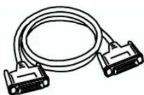
natural_image
Line drawing of a two-pin broadband cable with two connectors (no text or symbols)■ Clock cable

Use this to synchronize multiple DA-2496 units. For details, refer to Synchronization settings (p. 41).

It is not possible to use the DA-2496 simultaneously with the Roland RPC-1.

* DA-2496 doesn't work with the PCI Card slot providing 3.3V mode.

It is not possible to use the DA-2496 simultaneously with the Roland RPC-1.
■ 8 IN/8 OUT audio input/output with up to 24-bit/96 kHz quality
The DA-2496 supports eight channels of audio input and output simultaneously with astounding 24-bit/96 kHz quality, allowing pro-quality digital recording and playback. Sampling rates from 22.05–96 kHz are supported. MIDI input/output connectors and word clock input/output connectors are also standard.
Up to four DA-2496 units can be used simultaneously, letting you expand your system to 32 INs/32 OUTs. (Only on Windows Me/98.)
■ Internal digital mixer
The internal digital mixer can be controlled directly from the control panel of your computer. You can mix eight channels of input with audio data from your computer, and output the two-channel mix.
The Direct Monitor function lets you monitor in real time without passing the data through your computer application.
■ MIDI interface functionality
The DA-2496 provides a set of MIDI IN/OUT connectors, allowing it to be connected to MIDI devices for synchronization via MTC.
■ Included drivers
The included dedicated drivers for the DA-2496 support ASIO 2.0 for both Windows and Macintosh versions. A WDM drive for Windows 2000 is also included. You can enjoy enhanced performance with WDM-compatible applications such as SONAR, and ASIO-compatible applications such as Cubase and Logic. Of course, the DA-2496 can also be used with applications that support MME (Windows) or Sound Manager (Mac OS).
MEMO
In order to use the MIDI functionality of the DA-2496 on the Macintosh, you must install Opcode Corporation's OMS 2.3.3. Use the DA-PCI Driver CD-ROM to install this. For details, refer to Driver installation and settings (p. 18).
Names of things and what they do
DA-2496
■ Front panel

1. Clock select switch
This switches between the DA-2496's own internal clock and an external clock. (p. 40)
2. LOCK indicator
This will light when word clock is being received correctly from the DA-PCI or another digital device.
3. INPUT 1/2
These are combo-type jacks that allow either phantom-powered XLR balanced connections or TRS balanced connections. Condenser mics or audio devices that provide TRS balanced output can be connected here.
* This instrument is equipped with balanced (XLR/TRS) type input jacks. Wiring diagrams for these jacks are shown below. Make connections after first checking the wiring diagrams of other equipment you intend to connect.

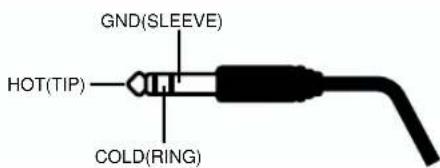
- Phantom power supply ON/OFF button (PHANTOM 48V) This switches the power supply on/off.
- -20 dBu/+4 dBu select switch (PAD 24 dB)
This switches the input level. When connecting a low output gain device such as a mic, set this to the OFF position.
- SENS knobs
These adjust the input level. - Peak indicators (PEAK)
These indicators will light in red at a point -6 dB below the level at which distortion begins. Adjust the SENS knobs so that the peak indicators do not light.

Always turn the phantom power off when connecting any device other than condenser microphones that require phantom power. You risk causing damage if you mistakenly supply phantom power to dynamic microphones, audio playback devices, or other devices that don't require such power. Be sure to check the specifications of any microphone you intend to use by referring to the manual that came with it. (This instrument's phantom power: 48 V DC, 10 mA Max)
4. INPUT 3/4
These are high impedance jacks that allow a guitar or bass to be connected.
- SENS knobs
These knobs adjust the input level.
• Peak indicators (PEAK)
These indicators will light in red at a point -6 dB below the level at which distortion begins. Adjust the SENS knobs so that the peak indicators do not light.
5. INPUT 5/6
- SENS knob
This knob adjusts the input level of the rear panel TRS balanced inputs (5/6). - Peak indicator (PEAK)
This indicator will light in red at a point -6 dB below the level at which distortion begins. Adjust the SENS knob so that the peak indicators do not light.
6. INPUT 7/8
This is an optical digital input jack that allows input from a CD/MD/DAT.
• DIGITAL/ANALOG select switch
This switches between the rear panel TRS balanced inputs (7/8) and the optical/coaxial digital inputs.
- SENS knob
If the select switch is set to the ANALOG position, this knob adjusts the input level of the rear panel TRS balanced inputs (7/8).
- Peak indicator (PEAK)
This indicator will light in red at a point -6 dB below the level at which distortion begins. Adjust the SENS knob so that the peak indicators do not light.
7. Headphone jack
Headphones can be connected here. At the default settings, the input from INPUT 1/2 will be monitored, but you can change the Control Panel settings (described later) to switch the input jacks that will be monitored. For details on the Control Panel, refer to DA-PCI Control Panel (p. 32).
8. Headphone volume knob
This knob adjusts the volume of the headphones.
9. OUTPUT indicators
When audio data is being output from the DA-2496, the corresponding output indicators will light to show the level.
10. Power switch
This turns the power of the DA-2496 on/off. The power is on when the switch is pressed in, and off when the switch is in the outward position. When the power is on, the indicator at the upper left of the power switch will light in green.
Lower position

Upper position


It is not possible to adjust the input level from the digital input jacks. You must adjust the output level of the playback device.
■ Rear panel
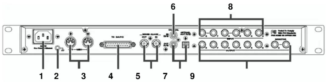
1. AC inlet
Connect the supplied AC power cord here. Plug it in firmly, so that it doesn't get pulled out accidentally. (For details on electrical current consumption, refer to Main Specifications (p. 45).)
2. Grounding terminal
This prevents the panel surface from developing an electrical charge.
3. MIDI IN/OUT connectors
These can be connected to the MIDI connectors of another MIDI device in order to transmit and receive MIDI messages.
4. DA-PCI cable connector
Connect the included DA-PCI cable to this connector.
5. WORD CLOCK IN/OUT connector
Use this when synchronizing with a digital recorder. This is also used in order to synchronize multiple DA-2496 units that are used together.
For details, refer to Synchronization settings (p. 41)
6. COAXIAL IN jack (7/8)
Use this jack to input digital audio from a CD/MD/DAT. If a digital device is connected to the optical digital input jack on the front panel, the optical digital input jack will take priority, and the signal from COAXIAL IN will not be input.
7. COAXIAL OUT jack/OPTICAL OUT jack (1/2)
Use this jack to make digital connections to a digital audio device such as a DAT or MD. You can use the included Control Panel application to change the output destination (1/2) to another number if desired.
8. TRS balanced input jacks (3–8)
External MIDI sound modules, synthesizers, CD players, MD players, etc., can be connected to these jacks. If an audio source is connected to the identically numbered input jack on the front panel, the front panel input will take priority, and the rear panel signal will not be input.
9. TRS balanced output jacks (1–8)
External stereo systems, amplified speakers, or mixers can be connected to these jacks.

Never use an AC power cord other than the one supplied with the DA-2496. Doing so can cause malfunction.

If a device is connected to the front panel optical digital input jack, the input of the optical digital input jack will take priority.
DA-PCI
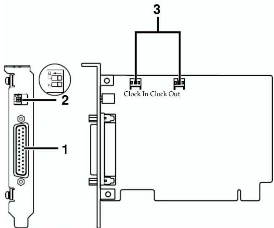
1. DA-PCI cable connector
Connect this to the DA-2496.
2. DP switch
Set SW1:OFF and SW2:OFF.
3. Clock In, Clock Out connectors
Use these to synchronize multiple DA-2496 units.
To avoid the risk of damage to internal components that can be caused by static electricity, please carefully observe the following whenever you handle the board.
- Before you touch the board, always first grasp a metal object (such as a water pipe), so you are sure that any static electricity you might have been carrying has been discharged.
- When handling the board, grasp it only by the panel or the board's edges. Avoid touching any of the electronic components or connectors.
- Before you connect any cables, make sure they do not carry a static electricity charge. Such charges can be transmitted, for example, if the other end of the cable has been in contact with a carpet (or other object) where there is a static electricity buildup.
- Save the bag in which the board was originally shipped, and put the board back into it whenever you need to store or transport it.

* DA-2496 doesn't work with the PCI Card slot providing 3.3V mode.

For details on synchronization when using multiple units simultaneously, please read Synchronization settings (p. 41).
French language
for Canadian Safety Standard
DA-PCI (French language)

1. DA-PCI cable connector
Connect this to the DA-2496.
2. DP switch
Set SW1:OFF and SW2:OFF.
3. Clock In, Clock Out connectors
Use these to synchronize multiple DA-2496 units.
For details on synchronization when using multiple units simultaneously, please read Synchronization settings (p. 41).
Preparations for using the DA-2496
Note for Windows 2000 users
If you are using Windows 2000, you must log on as Administrator when installing the VSC multi-pack. In addition, you must use the following procedure to check the Driver Signing Options settings.
- Start up Windows and log on as Administrator.
- Click the Start button of Windows, point to Settings, and click Control Panel. The Control Panel will open.
-
In the Control Panel, double-click System. The System Properties dialog box will appear.
-
Click the Hardware tab, and click the Driver Signing button. The Driver Signing Options dialog box will appear.

- Verify that the File signature verification is set to "Ignore." If not, change it to "Ignore."
- Click [OK].
- Turn off computer.

Installing the DA-PCI
Here's how to install the DA-PCI into the PCI slot of your computer. For details on installing PCI cards, refer to the owner's manual of your computer.
1
Turn off the power of your computer, and disconnect the power cord.
2
Remove the cover of your computer, and remove the cover of the PCI slot into which you will install the DA-PCI.
3
Insert the DA-PCI into the PCI slot. Make sure that the DA-PCI is oriented correctly. If it is oriented incorrectly, it cannot be inserted.
4
Fasten the DA-PCI using the screws that had held the PCI slot cover in place.
5
Re-attach the cover of your computer.
You must install the DA-PCI driver before you connect the DA-2496. Now please continue with Driver installation and settings (p. 18).
- When circuit board installation is complete, double-check your work.
- Always turn the unit off and unplug the power cord before attempting installation of the circuit board (DA-PCI).
- Install only the specified circuit board(s) (DA-PCI). Remove only the specified screws.

Do not touch any of the printed circuit pathways or connection terminals.

Never use excessive force when installing a circuit board. If it doesn't fit properly on the first attempt, remove the board and try again. remove the board and try again.
French language
for Canadian Safety Standard
Installation de la carte DA-PCI (French language)
If you change the File signature verification, you must restore the original setting after you have finished installing the DA-PCI driver and have restarted Windows. (To change the setting, you will need to log on as Administrator.)
Driver installation and settings
* You must install the DA-PCI driver before connecting the DA-2496.
* Disconnect the DA-2496 from the DA-PCI before you start up your computer.
The procedure for installation and settings will depend on your system. Please proceed to the explanation for your system.
- Windows Me...... p. 18
- Windows 98 ...... p. 19
- Windows 2000 ...... p. 21
• Macintosh ...... p. 26
■ Windows Me
1
Start up your computer.
2
The DA-PCI will be automatically detected, and the "Add new hardware wizard" will start up.
3
Insert the included DA-PCI Driver CD-ROM into the CD-ROM drive.
4
Check "Specify the location of the driver," and click "Next."

5
Check "Find best driver for currently used device" and "Specify search location." Then click "Browse."
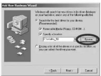
Select the CD-ROM drive (DA2496_drv), select the "WinMe_98" folder, and click the [OK] button.
When you return to the previous dialog box, click [Next].

6
When the dialog box shown at right appears, verify that Edirol DA-PCI is displayed, and click [Next].

7
When the dialog box shown at right appears, click [Next].
Installation will begin.

8
When the dialog box indicates "Edirol DA-PCI: Windows has finished installing the new hardware device," click "OK."

9
Installation will be completed, and the Windows desktop will appear.
Next, you need to connect the DA-2496 to the DA-PCI. Proceed to Connecting the DA-2496 to the DA-PCI (p. 23).
■ Windows 98
1
Start up your computer.
2
The DA-PCI will be detected automatically, and the "Add new hardware wizard" will start up.
Click [Next].
3
Insert the included DA-PCI Driver CD-ROM into the CD-ROM drive.
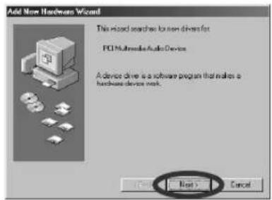
4
Check "Search for the best driver for your device" and click "Next."

5
Check "Specify search location," and then click "Browse." Select the CD-ROM drive (DA2496_drv), select the "WinMe_98" folder, and click the [OK] button.

6
Click "Next," and preparations for installation will be completed.
7
Click "Next" to begin the installation.

8
When the display indicates "Windows has finished installing the software that your new hardware device requires," click "OK."

9
The Windows desktop will appear.
Next, you need to connect the DA-2496 to the DA-PCI. Proceed to Connecting the DA-2496 to the DA-PCI (p. 23).
■ Windows 2000
1
Start up your computer.
Log on to Windows as a user with administrative privileges (such as Administrator).
2
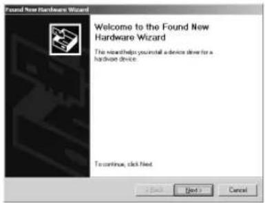
The DA-PCI will be detected automatically, and the "Found New Hardware Wizard" will appear. Click "Next."
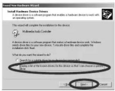
3
Check "Display of the list known drivers for this device so that I can choose a specific driver," and then click "Next."
4
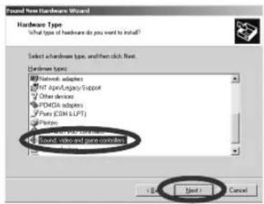
When the "Hardware type" dialog box appears, click "Sound, video, and game controllers," and click [Next].
5
Insert the DA-PCI Driver CD-ROM (included with the DA-2496) into the CD-ROM drive.
6
When the "Select device driver" dialog box appears, click "Have disk."

MEMO
If the display asks "Could not find digital signature. Continue installation?," click "Yes."
7
Specify the location of the driver data file.
From the CD-ROM drive (DA2496_drv) -> Win2000 folder, select DAPCI.INF, and click "Open."

8
Click "OK."
9
The dialog box shown at the right will appear. Click "Next."
* If more than one device driver is displayed, click the device driver that is displayed as DA-PCI.
![Found New Hardware Wizard Select a Device Driver Which driver do you want to install for this device? Select the manufacturers and models of your hardware device and then click Next. If you have a disk that contains the drive you want to install, click New Disk. Models: [ ] [ ] [ ] Save Disk... < Buy Edit > Cancel](/content/2026/05/976748/images/936b1713dc0e4a558a3016f4353442f02272a54b4ae85664b5da77a808bb8b72.jpg)
10
When the "Start installing the device driver" dialog box appears, click "Next."
11
Installation will begin.

12
When the display indicates "Completing the New Hardware Wizard finished. EDIROL DA-PCI: Windows are finished installing the Software for this device," click "OK."

13
When the dialog box shown at the right appears, click "Yes" to restart Windows.

Next, you need to connect the DA-2496 to the DA-PCI. Proceed to Connecting the DA-2496 to the DA-PCI (p. 23).

If the "Driver update notification" dialog box appears, click "Yes."

If the display indicates "Could not find digital signature... Continue installation?," click "Yes."
■ Connecting the DA-2496 to the DA-PCI
1
Turn off the power of your computer.
2
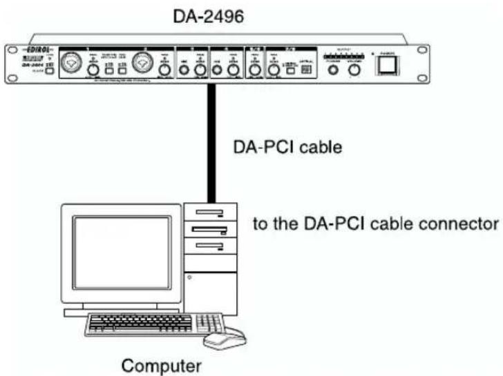
Connect the PCI cable included with the DA-2496 to the "TO DA-PCI" connector on the rear of the DA-2496. Then connect the other end of the DA-PCI cable to the connector of the DA-PCI.
3
Turn on the power of your computer.
4
Turn on the power of the DA-2496.
5
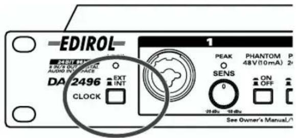
Make sure that the clock select switch located on the front panel of the DA-2496 is set to INT.
Next, you need to make the driver settings. Please proceed to Audio/MIDI input and output settings (p. 24).
NOTE
To prevent malfunction and/or damage to speakers or other devices, always turn down the volume, and turn off the power on all devices before making any connections.
NOTE
Once the connections have been completed, turn on power to your various devices in the order specified. By turning on devices in the wrong order, you risk causing malfunction and/or damage to speakers and other devices.
NOTE
This unit is equipped with a protection circuit. A brief interval (a few seconds) after power up is required before the unit will operate normally.
MEMO
For details on setting the clock select switch, refer to Synchronization settings (p. 41).
■ Audio/MIDI input and output settings
* If you are using the DA-2496 with a sequencer or similar application, please read the operation manual for your application.

Open the Control Panel.
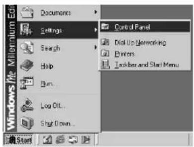
Click the Windows Start button, and from Settings, select the Control Panel.

Double-click the Sound and Multimedia icon (in Windows 98, the Multimedia icon).

Sounds and Multimedia

Multimedia

Click the Audio tab.
Set the Sound Playback, Sound Recording, and Preferred MIDI Music Playback as follows.
| Windows Me/98 Windows 2000 | |
| Sound Playback Wave | Out 1/2 EdirolDA-PCI Edirol DA-PCI |
| Sound Recording PCM | In 1/2 EdirolDA-PCI Edirol DA-PCI |
| MIDI Music Playback Medi | Out EdirolDA-PCI Edirol DA-PCI MIDI |
Windows Me/2000 Windows 98
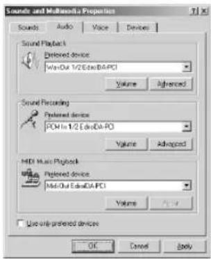


If you do not need to make audio/MIDI settings, proceed to Connecting the DA-2496 to the DA-PCI (p. 23).

If the Sound and Multimedia icon is not displayed, click "Display all Control Panel Options" from the frame at the left.
4
If you are using Windows 98, click the MIDI tab, and select MIDI Out Edirol DA-PCI for MIDI output.
5
Click [OK].
The window will close.

This completes the basic settings for the DA-2496 and DA-PCI. If you want to use the Direct Monitor function of the digital mixer built into the DA-PCI, refer to DA-PCI Control Panel (p. 32).

The standard driver included with Windows does not support ASIO.
■ Macintosh
Use the following procedure to install the DA-PCI driver.
* Disconnect the DA-2496 from your computer before starting up Macintosh.
* Exit all applications before you begin installing the driver.
* The DA-PCI OMS Driver included on the disc is provided as an additional module that allows the DA-PCI to be used with OMS. In order to use it, OMS must already be installed on the start-up hard disk.
To learn more about OMS
If you would like to learn more about OMS, please refer to "OMS_2.3_Mac.pdf" (on-line manual) located in the "OMS 2.3.8E" folder on the CD-ROM. In order to read "OMS_2.3_Mac.pdf," you will need the Adobe Acrobat Reader.
Installing the driver
1
Insert the included DA-PCI CD-ROM into the CD-ROM drive, and double-click the CD-ROM icon.
2
In the DA-PCI Driver CD-ROM, open the DA-2496 OMS Driver folder, and copy the Edirol DA-PCI Driver into the Extensions folder within the System folder.
3
Copy the DA-PCI OMS Driver into the OMS Folder within the System folder.


MEMO
To install OMS, double-click the Install OMS 2.3.8 icon located in the OMS 2.3.8E folder.
4
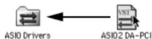
Copy ASIO2 DA-PCI to the specified location for your ASIO driver-compatible software. (In the case of Logic Audio or Cubase VST, this will be the ASIO Drivers folder.)
The following three ASIO drivers are included with the Mac version.
ASIO2 DA-PCI:
This driver supports ASIO 2.0.
ASIO Edirol DA-PCIv4:
This is an ASIO 2.0 driver without the Direct Monitor function.
If you are using Sound It!, copy only this driver to your ASIO Drivers folder.
ASIO Edirol DA-PCIv3:
This is an ASIO 1 driver for Digital Performer, Cubase 3, Reason, Reaktor, Unity, and Peak.
5
Copy the Edirol DA-PCI Control Panel to your hard disk (e.g., desktop).
6
Restart Mac OS.

Edirol DA-PCI ControlPanel
■ Connecting the DA-2496 to the DA-PCI

Turn off the power of your computer.

Connect the PCI cable included with the DA-2496 to the "TO DA-PCI" connector on the rear of the DA-2496. Then connect the other end of the DA-PCI cable to the connector of the DA-PCI.


Turn on the power of your computer.

Turn on the power of the DA-2496.

Make sure that the clock select switch located on the front panel of the DA-2496 is set to INT.

Next, you need to make the driver settings. Please proceed to OMS settings (p. 29).

To prevent malfunction and/or damage to speakers or other devices, always turn down the volume, and turn off the power on all devices before making any connections.

Once the connections have been completed, turn on power to your various devices in the order specified. By turning on devices in the wrong order, you risk causing malfunction and/or damage to speakers and other devices.

This unit is equipped with a protection circuit. A brief interval (a few seconds) after power up is required before the unit will operate normally.

For details on setting the clock select switch, refer to Synchronization settings (p. 41).
■ OMS settings
* If other MIDI devices are connected, you must turn off the power on all devices, and then make OMS settings according to the following procedure.
1
In the "Opcode" folder in the location where OMS is installed, open the "OMS Applications" folder, and double-click the "OMS Setup" icon.

OMS Setup
2
If the "Apple Talk" dialog box appears, click [Turn It Off].
Then, in the dialog box that appears next, click [OK].
3
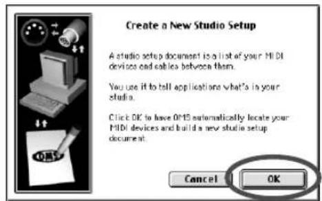
The "Create a New Studio setup" dialog box will appear. Click [OK].
4
The "OMS Driver Search" dialog box will appear. Click [Search].
5
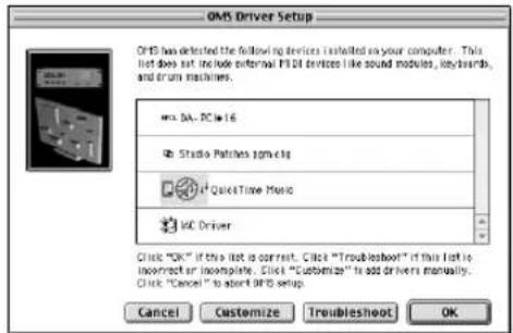
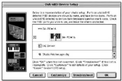
When the search ends, verify that DA-PCI 16 is listed in the OMS driver setting dialog box, and click [OK].



If you are using the DA-2496 with a sequencer, do not disconnect the MIDI cable connected to the DA-2496 while a song is playing back.

If the "Create a New Studio setup" dialog box does not appear, click [New Studio setup] in the [File] menu.

If an error dialog box is displayed during the setup, disconnect all MIDI cables connected to the DA-2496, and make the OMS settings once again.

Verify that the DA-PCI 16 is listed in the OMS MIDI device setting dialog box. Click [OK].

A dialog box will appear, allowing you to save the settings file.
Input the desired filename, and click [Save].

A settings window like the one shown at right will appear.

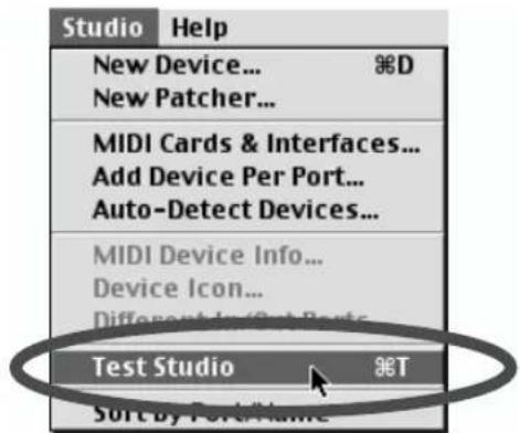
If a sound module is connected to a MIDI connector of the DA-2496, select [Test Studio] in the [Studio] Menu and check it in order to Test Studio whether sound is produced.

Turn on the power of the MIDI device connected to the DA-2496.

In the "My Studio Setup Window," click the keyboard icon.
When you move the mouse cursor near the keyboard icon, the cursor will change to the shape of an eighth note. Verify that you can hear sound from your sound module.


flowchart
graph TD
    A["MA-PC"] --> B["1"]
    B --> C["DA-PC"]
    D["IAC Driver"] --> E["Studio Patches ppm chg"]
    F["QuickTime Music"] --> G["1"]

flowchart
graph TD
    A["RFIC1"] --> B["1"]
    C["DA-PCI•16"] --> D["AND"]
    E["IAC Driver"] --> F["AND"]
    G["DA-PCI•16"] --> H["AND"]
    I["1"] --> J["AND"]
    K["AND"] --> L["AND"]

This is only one possible example of the settings window. The settings window that you actually see will differ depending on your system.

The following step will cause a relatively loud sound to be produced by the sound module, so turn down the volume of your sound module before continuing.

Since loud sounds may be produced, you should set your MIDI sound generator to a low volume setting.
12
After checking for sound, select the [Quit] command from the File menu to exit OMS Setup. If the Save dialog box appears, input a filename, and click [Save].
■ Sound Manager settings
* If you are using the DA-2496 with a sequencer or similar application, please read the operation manual for your application.
Sound Manager is the standard Mac OS digital sound specification. Sound Manager can handle only 16-bit two-channel input and output.
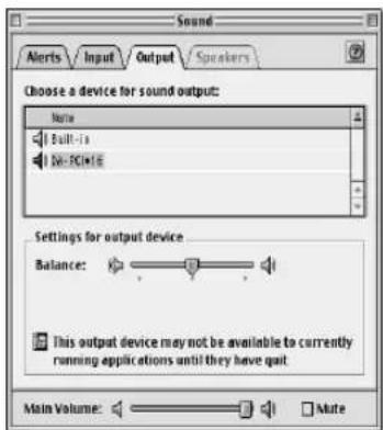
Use the following procedure to specify the DA-PCI as the Sound Manager output destination.
1
From the Apple menu, open Control Panels and then open Sound.
2
Select the Input tab and then the Output tab, and select the DA-PCI for input and output.
This completes basic settings for the DA-2496 and DA-PCI. If you want to use the Direct Monitor function of the digital mixer built into the DA-PCI, refer to DA-PCI Control Panel (p. 32).

Depending on your system, it may not be possible to select DA-PCI in Sound Manager.
DA-PCI Control Panel
When you install the DA-PCI driver, a dedicated “DA-PCI Control Panel” application will be installed along with the driver.
The Control Panel has the following major functions.
- Parameter settings for the various functions of the DA-PCI
- Input/output level meters
- Input/output mixing
Starting the Control Panel
Start up the DA-PCI Control Panel as follows.
Windows
Click the [Start] button, and choose Settings -> Control Panel -> Edirol DA-PCI H/W.
Macintosh
Double-click the "DA-PCI Control Panel" icon that you copied manually.
Signal flow
The flow of the principal signals is shown in the following table.
| DA In from the | DA-2496's inputs to the DA-PCI |
| DA Out from the | DA-PCI to the DA-2496's outputs |
| Wav In | from the DA-2496's inputs to the application's inputs |
| Wav Out from the | application to the Monitor Mixer and the DA-PCI |
| Mixer Input from the | application to the Monitor Mixer |

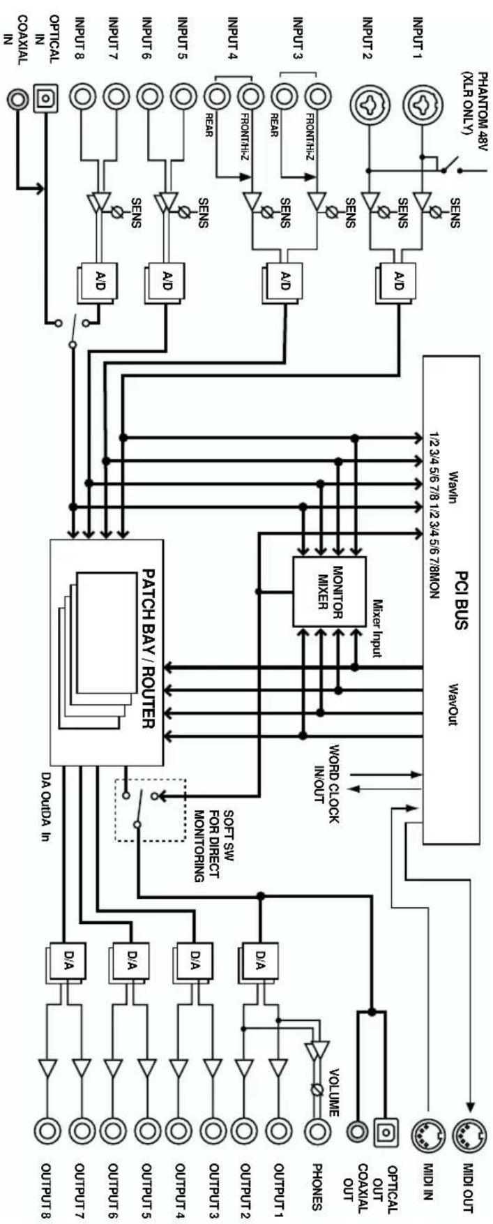
A larger block diagram is provided on p. 44.

flowchart
graph TD
    A["PHANTOM 48V (XLR ONLY)"] --> B["SENS"]
    C["INPUT 1"] --> D["SENS"]
    E["INPUT 2"] --> F["SENS"]
    G["INPUT 3"] --> H["SENS"]
    I["INPUT 4"] --> J["SENS"]
    K["INPUT 5"] --> L["SENS"]
    M["INPUT 6"] --> N["SENS"]
    O["INPUT 7"] --> P["SENS"]
    Q["INPUT 8"] --> R["SENS"]
    S["OPTICAL IN COAXIAL IN"] --> T["SENS"]
    B --> U["A/D"]
    D --> V["A/D"]
    F --> W["A/D"]
    H --> X["A/D"]
    J --> Y["A/D"]
    L --> Z["A/D"]
    N --> AA["A/D"]
    P --> AB["A/D"]
    R --> AC["A/D"]
    T --> AD["A/D"]
    U --> AE["Mixer Input"]
    V --> AE
    W --> AE
    X --> AE
    Y --> AE
    Z --> AE
    AA --> AE
    AB --> AE
    AC --> AE
    AD --> AE
    AE --> AF["PCI BUS"]
    AF --> AG["MONITOR MIXER"]
    AG --> AH["WORD CLOCK IN/OUT"]
    AH --> AI["MIDI OUT"]
    AH --> AJ["MIDI IN"]
    AK["VOLUME"] --> AL["D/A"]
    AL --> AM["OUTPUT 1"]
    AL --> AN["OUTPUT 2"]
    AL --> AO["OUTPUT 3"]
    AL --> AP["OUTPUT 4"]
    AL --> AQ["OUTPUT 5"]
    AL --> AR["OUTPUT 6"]
    AL --> AS["OUTPUT 7"]
    AL --> AT["OUTPUT 8"]
    AU["SOFT SW FOR DIRECT MONITORING"] --> AV["PACK BAY / ROUTER"]
    AW["DA OutDA In"] --> AX["PACK BAY / ROUTER"]
* The signals that are output from the DA-PCI can be selected in the Control Panel. For details, refer to Patchbay/Router (p. 34) in this chapter.
DA-PCI Control Panel
■ Monitor Mixer
Here you can adjust the input levels of the signals that are sent from WavOut to the Monitor Mixer.

1. Save button
Assign a name to settings and save them. (For the Macintosh version, this can be selected from the File menu.)
2. Delete button
Delete the saved settings. (The Macintosh version does not have this function.)
3. Load button
Load previously saved settings. (For the Macintosh version, select the File menu -> Open command.)
* DA-PCI Control Panel will automatically load the settings that were used most recently. This means that it is not necessary to save the settings each time you close the Control Panel. The Save and Load functions described above are used when you want to save several different settings under different filenames, and load them later.
4. H/W Installed
If multiple DA-PCI units are installed, select the DA-PCI for which you want to make settings.
5. Monitor Mixer
- Level meters... indicate the pre-fader level.
- Mixer Inputs faders... adjust the amount that is sent to Master.
- Solo... switch the Solo function on/off.
- Stereo Link... switch Stereo Link on/off.
- Master Volume... adjust the Master level.
* Fader and mute settings you make here will not affect the DA-PCI In or WavOut device.
6. Done button (Windows only)
When you finish making settings, click this button to close the Control Panel.
MEMO
At the default settings, all inputs of the Monitor Mixer are muted.
MEMO
Mixing is performed within the DA-PCI, and does not place a burden on the CPU.
MEMO
The S/PDIF tab is not available for use.
MEMO
For details on how DA-PCI units are numbered, refer to Synchronization settings (p. 41).
■ Patchbay/Router
When you click the Patchbay/Router tab, a screen like the following will appear. Here you can select which of the input sources being input to the DA-PCI will be sent from outputs DA Out 1/2 through DA Out 7/8. Normally, WavOut will be selected as the output.
For DA Out 1/2 you can also choose Monitor Mixer. If you select Monitor Mixer, all data being output from WavOut will be sent to DA Out 1/2.

■ Hardware Settings
When you click the Hardware Settings tab, a screen like the following will appear. Here you can make various settings for the DA-PCI, such as the master clock and the sampling frequency.

- Master Clock
Select the master clock.
- Int. Clock... The DA-PCI will be the word clock master. In this case, set the DA-2496's clock select switch to the INT (internal) position.
- Ext. Clock... The DA-PCI will synchronize to the DA-2496 (or to another DA-PCI). In this case, set the DA-2496 (or the other DA-PCI) to EXT (external).

Clock Sample Rate can be set to 22.05, 32, 44.1, 48, 88.2, and 96. Other sample rate settings cannot be used.

If the master clock is set to Ext. Clock, the sampling frequency cannot be changed from software.
- Int. Clock Sample Rate
Select the sampling frequency when the Master Clock is set to Int. Clock.
- Reset Rate When Idle... If this is checked, the sampling frequency will return to the value specified by the control panel when the device is released by the software.
- Ext. Clock Sample Rate
Select the sampling frequency when the Master Clock is set to Ext. Clock. Only the sampling frequency selected here can be used by software.
- Multitrack Driver Device (Windows Me/98 only)
Specify how the MME device will be handled by software.
- Single and In-Sync... When a certain software program handles all MME devices simultaneously, this ensures that each MME device is synchronized.
- Independent... Use this setting when each MME device is used by different software.
- Multiple Card Sync... When multiple DA-PCI units are used simultaneously, this ensures that they will be synchronized.
- DMA Buffer Size
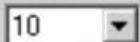
Specify the buffer size for MME (Windows), ASIO, and Sound Manager (Macintosh). The buffer size is closely related to latency, and decreasing the buffer size will also decrease the latency.
DMA Buffer Sizes
Wave
ASIO

ms per buffer
samples per buffer
When using Windows
2000, the DMA Buffer Size will be displayed as shown at the right.
When using
Macintosh, the DMA Buffer Size will be the Sound Manager input/output port select fields.
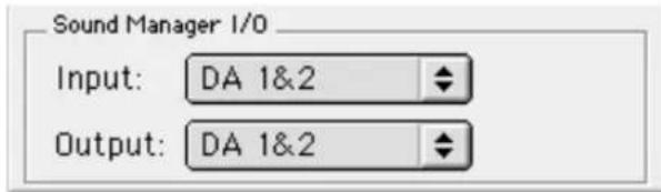
The default values for buffer size are as follows.
Windows: 20 ms
Macintosh: ASIO, Sound Manager 1024 bytes
- Disable Control of the Monitor Mixer and Patchbay/Router by Audio Applications (Windows Me/98 only)
If this is checked, the software (sequencer) will not be able to control the Monitor Mixer or Patchbay/Router.

Depending on the performance of your computer, the digital data may not be transferred correctly if the buffer is too small, causing noise. If this occurs, increase the buffer size.

Depending on your software, you may need to set the buffer size from your software. For details, refer to the operation manual for your software.
Troubleshooting
- Can’t install the DA-PCI into the computer
- Is the DA-PCI oriented correctly?
■ The DA-PCI Control Panel does not start up
- Is the DA-PCI correctly inserted in a PCI slot?
- Was the driver installed correctly?
■ No sound, cannot input sound
- Is the DA-PCI cable connected correctly?
- Is the DA-2496 clock select switch set correctly?
Audio cannot be input or output unless the DA-2496's clock select switch and the DA-PCI Control Panel "Master Clock" setting are set correctly. For details, refer to Connecting the DA-2496 to DA-PCI (p. 23, p. 28). - Mute may have been checked in the DA-PCI Control Panel "Monitor Mixer" tab.
If Mute is checked in the "Monitor Mixer" tab of the Control Panel, the audio output will be muted. Uncheck the Mute setting(s) in the Control Panel. For details on the Control Panel, refer to DA-PCI Control Panel (p. 32). - Are the input/output settings of your software correct?
Check the audio input/output settings of your software.
■ The volume level of the instrument connected to DA-2496 is too low.
- Could you be using a connection cable that contains a resistor? Use a connection cable that does not contain a resistor. (Roland: PCS cable or equivalent).
■ Can't use MIDI
- Is the DA-PCI cable connected correctly?
- Is the driver installed correctly?
Install the driver according to the procedure given in Driver installation and settings (p. 18). - Are the MIDI settings of your software correct?
Check the MIDI input/output settings of your software.
■ Noise is present in the sound
- Is synchronization occurring correctly with the PCI device?
For details, refer to Connecting the DA-2496 to DA-PCI (p. 23, p. 28). - If your computer has insufficient RAM, the system will not be able to perform as designed, and noise may be heard in the sound.
In this case, we recommend that you expand your memory to 128 MB or more of RAM.
- Depending on the performance of your computer, digital data may not be transferred correctly if the buffer size is too small, causing noise to be heard.
In this case, you should increase the buffer size. For details, refer to DA-PCI Control Panel (p. 32). Depending on your software, it may be necessary to set the buffer size from your software. For details, refer to the operation manual for your software.\
- Howling could be produced depending on the location of microphones relative to speakers. This can be remedied by:
- Changing the orientation of the microphone(s).
- Relocating microphone(s) at a greater distance from speakers.
- Lowering volume levels.
- When Word Clock is used, jitter from the master device may cause noise to occur.
If you are using Word Clock with another digital device as the master and the DA-2496 and DA-PCI as the slave, jitter from the master device may cause noise to occur.
■ When using SONAR, DA In 9/10 is displayed as an audio input source
- The Monitor Mixer input may be displayed as DA In 9/10.
Even in this case, DA In 9/10 can be used normally for the Monitor Mixer.
■ In Windows 2000, only one set of audio output destinations is displayed for SONAR.
- By performing the following procedure, you will be able to use four sets of audio with SONAR.
- From the Option menu, select Audio, and click the Advanced tab.
- In the Playback and Recording area, uncheck "Always Use MME Interface, Even When WDM Drivers Are Available."
- Click [OK].
- When the dialog box appears, restart SONAR.
- Once again select Audio from the Option menu, and click the Drivers tab.
- In the Input Drivers and Output Drivers area, click all devices named Edirol DA-PCI to highlight them.
- Next click the General tab, and select the device named Edirol DA-PCI as the Playback Timing Master and the Recording Timing master.
- Click [OK].
- When the dialog box appears, restart SONAR.
- When using Cubase on Windows 2000, can’t specify the audio output destination
- By performing the following procedure, you will be able to use four sets of audio with Cubase.
- From the Panels menu, select VST Inputs.
- Click the buttons indicated as DA In 1/2–DA In 7/8 and Mixer In L/R, getting them to light.
- Close the VST Inputs window.
- From the Panels menu, select VST Master Mixer.
- Drag the lower right of the window toward the right to expand the window.
- Click the [Active] buttons to make all of them light.
- Click the buttons located below the sliders to successively select DA Out 1/2-DA Out 7/8.
- Close the VST Master Mixer window.
- In the Arrangements window, click the Out area and select either Master, BUS2, BUS3, or BUS4.
- If you want the output to be stereo, select the track, and then click the [Stereo] button in Track Info.
- Can’t use the ASIO driver on the Macintosh
- You may have copied all of the ASIO drivers from the DA-PCI Driver CD-ROM into your ASIO Drivers folder.
If all of the ASIO drivers were copied from the DA-PCI Driver CD-ROM into your ASIO Drivers folder, it may not be possible for your software to select the DA-PCI ASIO driver. Please copy only the necessary file into the ASIO Drivers folder. For details, refer to About the drivers (p. 39).
About the drivers
When you install the DA-PCI, you will be able to use the following drivers. Refer to the manual for your software, and use the driver that best suits your environment.
WDM driver
Use this driver if you have set SONAR (or a similar application) to WDM driver mode. This provides the optimal audio performance, with high audio quality and low latency.
* 24-bit audio cannot be used with applications that do not support WDM, such as Cool Edit and Media Player.
ASIO driver
ASIO (Audio Stream In/Out) is a driver specification promoted by Steinberg Corporation which provides for the connection of audio software and audio hardware. ASIO supports both Windows and Macintosh platforms, and allows high-quality, multi-channel input and output. ASIO drivers that support ASIO 2.0 for both Windows (Me/98/2000) and Mac OS (8.6 or later) are included with the DA-PCI.
The following three types of ASIO driver are included with the Mac version.
ASIO2 DA-PCI:
This is an ASIO 2.0 compatible driver.
ASIO Edirol DA-PCIv4:
This is the ASIO 2.0 driver without the Direct Monitor function.
If you are using Sound It!, copy only this driver to the ASIO Drivers folder.
ASIO Edirol DA-PCIv3:
This is an ASIO 1 driver for Digital Performer, Cubase 3, Reason, Reaktor, Unity, and Peak.
EASI driver
EASI (Enhanced Audio Stream Interface) is a driver specification promoted by E-magic Corporation to connect audio software and audio hardware. As with ASIO, it supports both Windows and Macintosh platforms, and provides high-quality, multi-channel input and output. EASI drivers for Windows (Me/98/2000) are included with the DA-PCI.
MME driver (Windows)
Windows MME (Multi Media Extensions) is the standard Windows expansion specification for multimedia functionality.
If you want to specify the DA-2496 as the input/output for system sounds, make the following settings.
- From the "Start" menu, select "Control Panel" and then open "Multimedia."
- In the "Audio" tab, specify the DA-2496 as the input/output device in "Sound Playback/ Sound Recording."
Sound Manager driver (Macintosh)
Sound Manager is the standard digital sound specification for Mac OS. For both input and output, only 16-bit 2-channel audio can be handled by Sound Manager. For details on making Sound Manager settings, refer to Sound Manager settings (p. 31).
MIDI driver (Windows)
This is a driver for handling DA-2496 MIDI in Windows. A Windows MME-compatible MIDI driver is included with the DA-PCI.
OMS MIDI driver (Macintosh)
This is an OMS driver for handling DA-2496 MIDI on the Macintosh. OMS 2.3.3 or higher is required in order to use this. Opcode Corporation's OMS 2.3.3 MIDI driver is included on the DA-PCI Driver CD-ROM.
For details on making OMS driver settings, refer to OMS settings (p. 29).
Synchronization settings
DA-2496/ DA-PCI synchronization settings
In order to use the DA-2496/DA-PCI, you must set the word clock of each unit to either internal (INT), or external (EXT). You will need to set the DA-2496 and DA-PCI appropriately for your situation.
The word clock of the DA-2496 is selected using the clock select switch on its front panel. The word clock of the DA-PCI is selected through the Master Clock setting in the Hardware Settings section of the included Control Panel software.
■ Using the DA-2496/DA-PCI as the master
Set both the DA-2496 and DA-PCI to Internal. In this case, even if a signal of a sampling frequency differing from that of the master is received at the digital input jack of the DA-2496, it will be converted into the sampling frequency of the master, and sent to the computer.
If the settings are correct, the front panel LOCK indicator will light.


For details on the Control Panel, refer to DA-PCI Control Panel (p. 32).

If you are using the DA-2496 with a sequencer, the MIDI cables connected to the DA-2496 must not be disconnected while a song is playing.
Synchronization settings
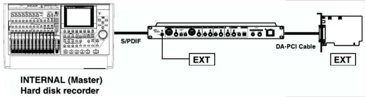
■ Using another hard disk recorder as the master
Set both the DA-2496 and DA-PCI to External. In this case, the sampling frequency of the DA-2496 and DA-PCI will be the same as the sampling frequency specified on the master device.
If the settings are correct, the front panel LOCK indicator will light.

flowchart
graph LR
    A["INTERNAL (Master) Hard disk recorder"] --> B["Word Clock"]
    B --> C["DA-PCI Cable"]
    C --> D["EXT"]
    C --> E["EXT"]
    style A fill:#f9f,stroke:#333
    style B fill:#ccf,stroke:#333
    style C fill:#cfc,stroke:#333
    style D fill:#fcc,stroke:#333
    style E fill:#cff,stroke:#333
Synchronization settings for multiple DA-PCI units
Up to four DA-PCI units can be used simultaneously in one computer. Each DA-PCI will be assigned a number from 1 through 4, following the order in which the cards are detected. (Usually, such detection occurs in numerical order, beginning with the lowest-numbered PCI slot.) Settings for each card are made from the DA-PCI control panel. When using multiple DA-PCI units simultaneously, all cards and PCI devices must be synchronized.
■ Synchronizing multiple DA-PCI units
In order to synchronize multiple DA-PCI units, the sampling frequency of all DA-PCI and DA-2496 units must match, and they must be using the same word clock. As shown below, there are two ways in which the word clock can be shared.
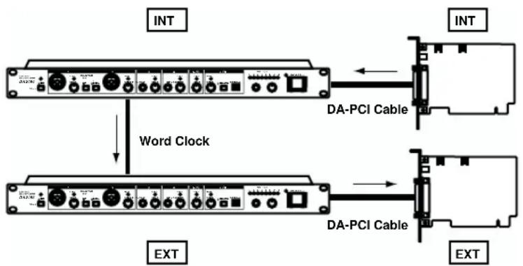
1. Supplying the word clock via PCI
flowchart
graph TD
    A["INT"] --> B["Word Clock"]
    B --> C["EXT"]
    D["INT"] --> E["DA-PCI Cable"]
    E --> F["EXT"]
    G["EXT"] --> H["DA-PCI Cable"]
    H --> I["EXT"]
The word clock is supplied to multiple DA-PCI units via the DA-2496. For each slave DA-PCI (units to which the word clock is being supplied), set the master clock to Ext. Clock.
2. Using the included clock cable to supply the word clock

flowchart
graph TD
    A["DA-PCI Cable"] --> B["Clock In"]
    A --> C["Clock Cable"]
    D["INTINT"] --> E["Clock Out"]
    F["EXTINT"] --> G["Clock In"]
The word clock is supplied to multiple DA-PCI units via the clock cable. In this case, use the included clock cable to connect the Clock Out connector of the master unit (INTERNAL) to the Clock In connector of the slave unit (EXTERNAL). On each slave (EXTERNAL) DA-PCI unit, set the master clock setting to Ext. Clock.

Simultaneous use of multiple DA-PCI units is not supported for Windows 2000 and Macintosh.

For details on the Control Panel, refer to DA-PCI Control Panel (p. 32).

If a clock cable is connected to the Clock In connector, the clock from the Clock In connector will take priority. If you want to supply the word clock via PCI, disconnect the clock cable.

If you are using a sampling frequency of 88.2 kHz or 96 kHz, it is not possible to synchronize multiple DA-PCI units via a clock cable. Please supply the word clock via the PCI cable.
Block diagram
flowchart
graph TD
    subgraph Input Port1
        direction TB
        A["OPTICAL OUT COXIAL OUT"] --> B["OPTICAL"]
        C["MIDI IN"] --> D["MINI OUT"]
    end

    subgraph Input Port2
        direction TB
        E["INPUT 1"] --> F["INPUT 2"]
        G["INPUT 3"] --> H["INPUT 4"]
        I["INPUT 5"] --> J["INPUT 6"]
        K["INPUT 7"] --> L["INPUT 8"]
    end

    subgraph Input Port3
        direction TB
        M["VOLUME"] --> N["VOLUME"]
        O["OUTPUT 1"] --> P["VOLUME"]
        Q["VOLUME"] --> R["VOLUME"]
        S["VOLUME"] --> T["VOLUME"]
        U["VOLUME"] --> V["VOLUME"]
        W["VOLUME"] --> X["VOLUME"]
    end

    subgraph Input Port4
        direction TB
        Y["OPTICAL OUT COXIAL OUT"] --> Z["MIDI OUT"]
    end

    subgraph Input Port5
        direction TB
        AA["VOLUME"] --> AB["VOLUME"]
        AC["VOLUME"] --> AD["VOLUME"]
        AE["VOLUME"] --> AF["VOLUME"]
        AG["VOLUME"] --> AH["VOLUME"]
    end

    subgraph Input Port6
        direction TB
        AI["VOLUME"] --> AJ["VOLUME"]
        AK["VOLUME"] --> AL["VOLUME"]
        AM["VOLUME"] --> AN["VOLUME"]
        AO["VOLUME"] --> AP["VOLUME"]
        AQ["VOLUME"] --> AR["VOLUME"]
    end

    subgraph Input Port7
        direction TB
        AS["VOLUME"] --> AT["VOLUME"]
        AU["VOLUME"] --> AV["VOLUME"]
        AW["VOLUME"] --> AX["VOLUME"]

    subgraph Input Port8
        direction TB
        AY["D/A"] --> AZ["D/A"]
        BA["D/A"] --> BB["D/A"]
        BC["D/A"] --> BD["D/A"]
    end

    subgraph Input Port9
        direction TB
        BE["A/D"] --> BF["A/D"]
        BG["A/D"] --> BH["A/D"]
    end

    subgraph Input Port10
        direction TB
        BI["SENS"] --> BJ["SENS"]
        BK["SENS"] --> BL["SENS"]
    end

    subgraph Input Port11
        direction TB
        BM["SENS"] --> BN["SENS"]
        BO["SENS"] --> BP["SENS"]
    end

    subgraph Input Port12
        direction TB
        BQ["SENS"] --> BR["SENS"]
        BS["SENS"] --> BT["SENS"]
    end

    subgraph Input Port13
        direction TB
        CA["SENS"] --> CB["SENS"]
        CC["SENS"] --> DA["SENS"]
    end

    subgraph Input Port14
        direction TB
        DB["SENS"] --> DC["SENS"]
        DD["SENS"] --> EE["SENS"]
    end

    subgraph Input Port15
        direction TB
        FL["SENS"] --> DG["SENS"]
        DH["SENS"] --> DI["SENS"]
    end

    subgraph Input Port16
        direction TB
        EY["SENS"] --> ZE["SENS"]
        ZE["SENS"] --> BZ["SENS"]
    end

    subgraph Input Port17
        direction TB
        BAZ["SENS"] --> BBZ["SENS"]
        BCZ["SENS"] --> BDZ["SENS"]
    end

    subgraph Input Port18
        direction TB
        BZS["SENS"] --> CCZ["SENS"]
        CCZ["SENS"] --> DZS["SENS"]
    end

    subgraph Input Port19
        direction TB
        BZS2["SENS"] --> CCZ2["SENS"]
        CCZ2["SENS"] --> DZS2["SENS"]
    end

    subgraph Input Port20
        direction TB
        BZS3["SENS"] --> CCZ3["SENS"]
        CCZ3["SENS"] --> DZS3["SENS"]
    end

    subgraph Input Port21
        direction TB
        BZS4["SENS"] --> CCZ4["SENS"]
        CCZ4["SENS"] --> DZS4["SENS"]
    end

    subgraph Input Port22
        direction TB
        BZS5["SENS"] --> CCZ5["SENS"]
        CCZ5["SENS"] --> DZS5["SENS"]
    end

    subgraph Input Port23
        direction TB
        BZS6["SENS"] --> CCZ6["SENS"]
        CCZ6["SENS"] --> DZS6["SENS"]
    end

    subgraph Input Port24
        direction TB
        BZS7["SENS"] --> CCZ7["SENS"]
        CCZ7["SENS"] --> DZS7["SENS"]
    end

    subgraph Input Port25
        direction TB
        BZS8["SENS"] --> CCZ8["SENS"]
        CCZ8["SENS"] --> DZS8["SENS"]
    end

    subgraph Input Port26
        direction TB
        BZS9["SENS"] --> CCZ9["SENS"]
        CCZ9["SENS"] --> DZS9["SENS"]
    end

    subgraph Input Port27
        direction TB
        BZS10["SENS"] --> CCZ10["SENS"]
        CCZ10["SENS"] --> DZS10["SENS"]
    end

    subgraph Input Port28
        direction TB
        BZS11["SENS"] --> CCZ11["SENS"]
        CCZ11["SENS"] --> DZS11["SENS"]
    end

    subgraph Input Port29
        direction TB
        BZS12["SENS"] --> CCZ12["SENS"]
        CCZ12["SENS"] --> DZS12["SENS"]
    end

    subgraph Input Port30
        direction TB
        BZS13["SENS"] --> CCZ13["SENS"]
        CCZ13["SENS"] --> DZS13["SENS"]
    end

    subgraph Input Port31
        direction TB
        BZS14["SENS"] --> CCZ14["SENS"]
        CCZ14["SENS"] --> DZS14["SENS"]
    end

    subgraph Input Port32
        direction TB
        BZS15["SENS"] --> CCZ15["SENS"]
        CCZ15["SENS"] --> DZS15["SENS"]
    end

    subgraph Input Port33
        direction TB
        BZS16["SENS"] --> CCZ16["SENS"]
        CCZ16["SENS"] --> DZS16["SENS"]
    end

    subgraph Input Port34
        direction TB
        BZS17["SENS"] --> CCZ17["SENS"]
        CCZ17["SENS"] --> DZS17["SENS"]
    end

    subgraph Input Port35
        direction TB
        BZS18["SENS"] --> CCZ18["SENS"]
        CCZ18["SENS"] --> DZS18["SENS"]
    end

    subgraph Input Port36
        direction TB
        BZS19["SENS"] --> CCZ19["SENS"]
        CCZ19["SENS"] --> DZS19["SENS"]
    end

    subgraph Input Port37
        direction TB
        BZS20["SENS"] --> CCZ20["SENS"]
        CCZ20["SENS"] --> DZS20["SENS"]
    end

    subgraph Input Port38
        direction TB
        BZS21["SENS"] --> CCZ21["SENS"]
        CCZ21["SENS"] --> DZS21["SENS"]
    end

    subgraph Input Port39
        direction TB
        BZS22["SENS"] --> CCZ22["SENS"]
        CCZ22["SENS"] --> DZS22["SENS"]
    end

    subgraph Input Port40
        direction TB
        BZS23["SENS"] --> CCZ23["SENS"]
        CCZ23["SENS"] --> DZS23["SENS"]
    end

    subgraph Input Port41
        direction TB
        BZS24["SENS"] --> CCZ24["SENS"]
        CCZ24["SENS"] --> DZS24["SENS"]
    end

    subgraph Input Port42
        direction TB
        BZS25["SENS"] --> CCZ25["SENS"]
        CCZ25["SENS"] --> DZS25["SENS"]
    end

    subgraph Input Port43
        direction TB
        BZS26["SENS"] --> CCZ26["SENS"]
        CCZ26["SENS"] --> DZS26["SENS"]
    end

    subgraph Input Port44
        direction TB
        BZS27["SENS"] --> CCZ27["SENS"]
        CCZ27["SENS"] --> DZS27["SENS"]
    end

    subgraph Input Port45
        direction TB
        BZS28["SENS"] --> CCZ28["SENS"]
        CCZ28["SENS"] --> DZS28["SENS"]
    end

    subgraph Input Port46
        direction TB
        BZS29["SENS"] --> CCZ29["SENS"]
        CCZ29["SENS"] --> DZS29["SENS"]
    end

    subgraph Input Port47
        direction TB
        BZS30["SENS"] --> CCZ30["SENS"]
        CCZ30["SENS"] --> DZS30["SENS"]
    end

    subgraph Input Port48
        direction TB
        BZS31["SENS"] --> CCZ31["SENS"]
        CCZ31["SENS"] --> DZS31["SENS"]
    end

    subgraph Input Port49
        direction TB
        BZS32["SENS"] --> CCZ32["SENS"]
        CCZ32["SENS"] --> DZS32["SENS"]
    end

    subgraph Input Port50
        direction TB
        BZS33["SENS"] --> CCZ33["SENS"]
        CCZ33["SENS"] --> DZS33["SENS"]
    end

    subgraph Input Port51
        direction TB
        BZS34["SENS"] --> CCZ34["SENS"]
        CCZ34["SENS"] --> DZS34["SENS"]
    end

    subgraph Input Port52
        direction TB
        BZS35["SENS"] --> CCZ35["SENS"]
        CCZ35["SENS"] --> DZS35["SENS"]
    end

    subgraph Input Port53
        direction TB
        BZS36["SENS"] --> CCZ36["SENS"]
        CCz6-SNS & OUTDOOUTDOOUTDOOUTDOOUTDOOUTDOOUTDOOUTDOOUTDOOUTDOOUTDOOUTDOOUTDOOUTDOOUTDOOUTDOOUTDOOUTDOOUTDOOUTDOOUTDOOUTDOOUTDOOUTDOOUTDOOUTDOOUTDOOUTDOOUTDOOUTDOOUTDOOUTDOOUTDOOUTDOOUTDOOUTDOOUTDOOUTDOOUTDOOUTDOOUTDOOUTDOOUTDOOUTDOOUTDOOUTDOOUTDOOUTDOOUTDOOUTDOOUTDOOUITDINNININININININININININININININININININININININININININININININININININININININININININININININININININININININININININININININININININININININININININININININININININININININININININININININININININININ IN-IN IN-IN IN-IN IN-IN IN-IN IN-IN IN-IN IN-IN IN-IN IN-IN IN-IN IN-IN IN-IN IN-IN IN-IN IN-IN IN-IN IN-IN IN-IN IN-IN IN-IN IN-IN IN-IN IN-IN IN-IN IN-IN IN-IN IN-IN IN-IN IN-IN IN-IN IN-IN IN-IN IN-IN IN-IN IN-IN IN-IN IN-IN IN-IN IN-IN IN-IN IN-IN IN-IN IN-IN IN-IN IN-IN IN-IN IN-IN IN-IN IN-IN IN-I NIN IN IN-IN IN-IN IN-IN IN-IN IN-IN IN-IN IN-IN IN-IN IN-IN IN-IN IN-IN IN-IN IN-IN IN-IN IN-IN IN-IN IN-IN IN-IN IN-IN IN-IN IN-IN IN-IN IN-IN IN-IN IN-IN IN-IN IN-IN IN-IN IN-IN IN-IN IN-IN IN-IN IN-IN IN-IN IN-IN IN-IN IN-IN IN-IN IN-IN IN-IN IN-IN IN-IN IN-IN IN-IN IN-IN IN-IN IN-IN In-IN In-IN In-In In-In In-In In-In In-In In-In In-In In-In In-In In-In In-In In-In In-In In-In In-In In-In In-In In-In In-In In-In In-In In-In In-In In-In In-In In-In In-In In-In In-In In-In In-In In-In In-In In-In In-In In-In In-In In-In In-In In-In In-In In-In In-In In-In In-In In-In In-In In-In In-In In-In In-INA NO.

    %% Subgraph Output Port: PCI BUS Wavelet; WAIN; SWORD CLOCK CLK; WORD CLICK INPUT; WORO CLOCK CLK; WORD CLOCK CLK; WORD CLOCK CLK; WORD CLOCK CLK; WORD CLOCK CLK; WORD CLOCK CLK; WORD CLOCK CLK; WORD CLOCK CLK; WORD CLOCK CLK; WORD CLOCK CLK; WORD CLOCK CLK; WORD CLOCK CLK; WORD CLOCK CLK; WORD CLOCK CLK; WORD CLOCK CLK; WORD CLOCK CLK; WORD CLOCK CLK; WORD CLOCK CLK; WORD CLOCK CLK; WORD CLOCK CLK; WORD CLOCK CLK; WORD CLOCK CLK; WORD CLOCK CLK; WORD CLOCK CLK; WORD CLOCK CLK; WORD CLOCK CLK; WORO CLOCK CLK; WORD CLOCK CLK; WORD CLOCK CLK; WORD CLOCK CLK; WORD CLOCK CLK; WORD CLOCK CLK; WORD CLOCK CLK; WORD CLOCK CLK; WORD CLOCK CLK; WORD CLOCK CLK; WORD CLOCK CLK; WORD CLOCK CLK; WORD COLDING SENSE SENSE SENSE SENSE SENSE SENSE SENSE SENSE SENSE SENSE SENSE SENSE SENSE SENSE SENSE SENSE SENSE SENSE SENSE SENSE SENSE SENSE SENSE SENSE SENSE SENSE SENSE SENSE SENSE SENSE SENSE SENSE SENSE SENSE SENSE SENSE SENSE SENSE SENSE SENSE SENSE SENSE SENSE SENSE SENSE SENSE SENSE SENSE SENSE SENSE SASESSA SESSA SESSA SESSA SESSA SESSA SESSA SESSA SESSA SESSA SESSA SESSA SESSA SESSA SESSA SESSA SESSA SESSA SESSA SESSA SESSA SESSA SESSA SESSA SESSA SESSA SESSA SESSA SESSA SESSA SESSA SESSA SESSA SESSA SECCSESESESESESESESESESESESESESESESESESESESESESESESESESESESESESESESESESESESESESESESESESESESESESESESESESESESESESESESESESESESESESESESESESESESESESESESESESESESESESESESESESESESESESESESESESESESESESESESESESESESESTRENDRENDRENDRENDRENDRENDRENDRENDRENDRENDRENDRENDRENDRENDRENDRENDRENDRENDRENDRENDRENDRENDRENDRENDRENDRENDRENDRENDRENDRENDRENDRENDRENDRENDRENDRENDRENDRENDRENDRENDRENDRENDRENDRENDRENDRENDRENDRENDRENDRENDREDDNEEDNEEDNEEDNEEDNEEDNEEDNEEDNEEDNEEDNEEDNEEDNEEDNEEDNEEDNEEDNEEDNEEDNEEDNEEDNEEDNEEDNEEDNEEDNEEDNEEDNEEDNEEDNEEDNEEDNEEDNEEDNEEDNEEDNEEDNEEDNEEDNEEDNEEDNEEDNEEDNEEDNEEDNEEDNEEDNEEDNEEDNEEDNEEDNEEDNEEDNEEEDNEEDNEEDNEEDNEEDNEEDNEEDNEEDNEEDNEEDNEEDNEEDNEEDNEEDNEEDNEEDNEEDNEEDNEEDNEEDNEEDNEEDNEEDNEEDNEEDNEEDNEEDNEEDNEEDNEEDNEEDNEEDNEEDNEEDNEEDNEEDNEEEDNEEEDNEEEDNEEEDNEEEDNEEEDNEEEDNEEEDNEEEDNEEEDNEEEDNEEEDNEEEDNEEEDNEEEDNEEEDNEEEDNEEEDNEEEDNEEEDNDEEENDEEENDEEENDEEENDEEENDEEENDEEENDEEENDEEENDEEENDEEENDEEENDEEENDEEENDEEENDEEENDEEENDEEENDEEENDEEENDEEENDEEENDEEENDEEENDEEENDEEENDEEENDEEENDEEENDEEENDEEENDEEENDEEENDEEENDEEFEEFEEFEEFEEFEEFEEFEEFEEFEEFEEFEEFEEFEEFEEFEEFEEFEEFEEFEEFEEFEEFEEFEEFEEFEEFEEFEEFEEFEEFEEFEEFEEFEEFEEFEEFEEFEEFEEFEEFEEFEEFEEFEEFEEFEEFEEFEEFEEFEEFEE FEEFEEFEEFEEFEEFEEFEEFEEFEEFEEFEEFEEFEEFEEFEEFEEFEEFEEFEEFEEFEEFEEFEEFEEFEEFEEFEEFEEFEEFEEFEEFEEFEEFEEFEEFEE FEE FEE FEE FEE FEE FEE FEE FEE FEE FEE FEE FEE FEE FEE FEE FEE FEE FEE FEE FEE FEE FEE FEE FEE FEE FEE FEE FEE FEE FEE FEE FEE FEE FEE FEE FEE FEE FEE FEE FEE FEE FFE FFE FFE FFE FFE FFE FFE FFE FFE FFE FFE FFE FFE FFE FFE FFE FFE FFE FFE FFE FFE FFE FFE FFE FFE FFE FFE FFE FFE FFE FFE FFE FFE FFE FFE FFE FFE FFE FFE FFE FFE FFE FFE FFE FFE FFE FFE FFE FFE FFE FFL FE FE FE FE FE FE FE FE FE FE FE FE FE FE FE FE FE FE FE FE FE FE FE FE FE FE FE FE FE FE FE FE FE FE FE FE FE FE FE FE FE FE FE FE FE FE FE FE FE FE FE FE FE FE FE FE FE FE FE FE FE FE FE FE FE FE FE FE FE FE FE FE FE FE FE FE FE FE FE FE FE FE FE FE FE FE FE FE FE FE FE FE FE FE FE FE FE FE FE FE FOET FOET FOET FOET FOET FOET FOET FOET FOET FOET FOET FOET FOET FOET FOET FOET FOET FOET FOET FOET FOET FOET FOET FOET FOET FOET FOET FOET FOET FOET FOET FOET FOET FOET FOET FOET FOET FOET FOET FOET FOET FOET FOET FOET FOET FOET FOET FOET FOET FOET FO ET FO ET FO ET FO ET FO ET FO ET FO ET FO ET FO ET FO ET FO ET FO ET FO ET FO ET FO ET FO ET FO ET FO ET FO ET FO ET FO ET FO ET FO ET FO ET FO ET FO ET FO ET FO ET FO ET FO ET FO ET FO ET FO ET FO ET FO ET FO ET FO ET FO ET FO ET FO ET FO ET FO ET FO ET FO ET FO ET FO ET FO ET FO ET FO ET FO ET FO,FO,FO,FO,FO,FO,FO,FO,FO,FO,FO,FO,FO,FO,FO,FO,FO,FO,FO,FO,FO,FO,FO,FO,FO,FO,FO,FO,FO,FO,FO,FO,FO,FO,FO,FO,FO,FO,FO,FO,FO,FO,FO,FO,FO,FO,FO,FO,FO,FO,FO,PO,PO,PO,PO,PO,PO,PO,PO,PO,PO,PO,PO,PO,PO,PO,PO,PO,PO,PO,PO,PO,PO,PO,PO,PO,PO,PO,PO,PO,PO,PO,PO,PO,PO,
            |          |
            |          |
            |          |
            |          |
            |          |
            |          |
            |          |
            |          |
            |          |
            |          |
            |          |
            |          |
            |          |
            |          |
            |          |
            |          |
            |          |
            |          |
            |          |
            |          |
            |          |
            |          |
            |          |
            |          |
            |          |
            |          |
Main Specifications
■ DA-2496
Singnal Processing
AD conversion: 24-bit, 64 times oversampling (8 channels)
DA conversion: 24-bit, 128 times oversampling (8 channels)
Sampling Rate
CLOCK SOURCE = INTERNAL: 22.05, 32, 44.1, 48, 88.2, 96 kHz
CLOCK SOURCE = EXTERNAL: 32, 44.1, 48, 88.2, 96 kHz
Monitor Mixer
Number of Input Channels: 16
Number of Output Channels: 2
Fader: -144 to 0 dB
Internal Processing: 36-bit
Normal Input Level
Input 1 to 2: -60 to +4 dBu
Input 3 to 8 : -50 to +4 dBu
Normal Output Level
Output 1 to 8: +4 dBu (balanced)
Input Impedance
Input 1 to 8: 24 k ohms (XLR, TRS)
Input 3, 4: 470 k ohms (Hi-Z)
Output Impedance
Output 1 to 8: 300 ohms
Recommended Load Impedance
Output 1 to 8: 10 k ohms
Headphones jack: 20 to 600 ohms
Frequency Response
96.0 kHz: 20 Hz to 40 kHz (+0 dB / -2 dB)
48.0 kHz: 20 Hz to 22 kHz (+0 dB / -2 dB)
44.1 kHz: 20 Hz to 20 kHz (+0 dB / -2 dB)
Residual Noise Level
Ch. 1 to 8: -85 dBu or less (input terminated with 1 k ohms, INPUT SENS = LINE, IHF-A, typ.)
Connectors
Input jacks 1, 2: XLR type (phantom power), 1/4" TRS phone type
Input jacks 3, 4: 1/4" TRS phone type, 1/4" phone type (Hi-Z)
Input jacks 5 to 8: 1/4" TRS phone type
Output jacks 1 to 8: 1/4" TRS phone type
Headphones jack: Stereo 1/4" phone type
Digital In connectors: Optical type, Coaxial type (conform to S/P DIF)
Digital Out connectors: Optical type, Coaxial type (conform to S/P DIF)
MIDI connectors (in x 1, out x 1): 5-pin DIN type
Word Clock input jack: BNC type
Word Clock output jack: BNC type
DA-PCI connector: 25-pin D-sub type
Power Supply
AC 117 V, AC 230 V, AC 240 V
Power Consumption:
14 W (AC 117 V, AC 230 V, AC 240 V)
Demensions:
482 (W) × 223 (D) × 44 (H) mm / 19 (W) × 8-13/16 (D) × 1-3/4 (H) inches
Weight:
2.65 kg / 5 lbs 14 oz
Accessories
Owner's Manual
Driver CD-ROM
Interface Card (DA-PCI)
DA-PCI Cable (2 m)
Power cord
Clock cable
$$ (0 \mathrm{dBu} = 0. 7 7 5 \mathrm{Vrms}) $$
* In the interest of product improvement, the specifications and/or appearance of this unit are subject to change without prior notice.

For EU Countries
This product complies with the requirements of European Directives EMC 89/336/EEC and LVD 73/23/EEC.
For the USA
FEDERAL COMMUNICATIONS COMMISSION RADIO FREQUENCY INTERFERENCE STATEMENT
This equipment has been tested and found to comply with the limits for a Class B digital device, pursuant to Part 15 of the FCC Rules. These limits are designed to provide reasonable protection against harmful interference in a residential installation. This equipment generates, uses, and can radiate radio frequency energy and, if not installed and used in accordance with the instructions, may cause harmful interference to radio communications. However, there is no guarantee that interference will not occur in a particular installation. If this equipment does cause harmful interference to radio or television reception, which can be determined by turning the equipment off and on, the user is encouraged to try to correct the interference by one or more of the following measures:
– Reorient or relocate the receiving antenna.
– Increase the separation between the equipment and receiver.
- Connect the equipment into an outlet on a circuit different from that to which the receiver is connected.
- Consult the dealer or an experienced radio/TV technician for help.
This device complies with Part 15 of the FCC Rules. Operation is subject to the following two conditions:
(1) This device may not cause harmful interference, and
(2) This device must accept any interference received, including interference that may cause undesired operation.
Tested To Comply With FCC Standards
FOR HOME OR OFFICE USE
Unauthorized changes or modification to this system can void the users authority to operate this equipment.
This equipment requires shielded interface cables in order to meet FCC class B Limit.
For the USA
DECLARATION OF CONFORMITY Compliance Information Statement
Model Name : DA-2496
Type of Equipment : Digital Audio Interface
Responsible Party : Edirol Corporation North America
Address: 425 Sequoia Drive, Suite 114, Bellingham, WA 98226
Telephone : (360) 594-4276
For Canada
NOTICE
This Class B digital apparatus meets all requirements of the Canadian Interference-Causing Equipment Regulations.
AVIS
170 Admiral Boulevard
Mississauga On L5T 2N6
CANADA
TEL: (905) 362 9707
U. S. A.
Roland Corporation U.S.
5100 S. Eastern Avenue
Los Angeles, CA 90040-2938,
U.S.A.
TEL: (323) 890 3700
AFRICA
EGYPT
Al Fanny Trading Office
9, EBN Hagar A1 Askalany
Street,
ARD E1 Golf, Heliopolis,
Cairo 11341, EGYPT
TEL: 20-2-417-1828
REUNIÓN
Royal Cape Park, Unit 24
Londonderry Road, Ottery 7800
Cape Town, SOUTH AFRICA
TEL: (021) 799 4900
ASIA
CHINA
Roland Shanghai Electronics
Co., Ltd.
5F. No.1500 Pingliang Road
Shanghai 200090, CHINA
TEL: (021) 5580-0800
Roland Shanghai Electronics
Co,Ltd.
(BEIJING OFFICE)
10F. No.18 3 Section Anhuaxili
Chaoyang District Beijing
100011 CHINA
TEL: (010) 6426-5050
Roland Shanghai Electronics
Co., Ltd.
(GUANGZHOU OFFICE)
2/F., No.30 Si You Nan Er Jie
Yi Xiang, Wu Yang Xin Cheng
Guangzhou 510600, CHIN
TEL: (020) 8736-0428
HONG KONG
Parsons Music Ltd.
8th Floor, Railway Plaza, 39
Chatham Road South, T.S.T,
Kowloon, HONG KONG
TEL: 2333 1863
INDIA
Rivera Digitec (India) Pvt. Ltd.
409, Nirman Kendra
Mahalaxmi Flats Compound
Off. Dr. Edwin Moses Road,
Mumbai-400011, INDIA
TEL: (022) 2493 9051
INDONESIA
PT Citra IntiRama
J1. Cideng Timur No. 15J-150
Jakarta Pusat
INDONESIA
TEL: (021) 6324170
KOREA
Cosmos Corporation
1461-9, Seocho-Dong,
Scocho Ku, Seoul, KOREA
TEL: (02) 3486-8855
MALAYSIA/
SINGAPORE
Roland Asia Pacific Sdn. Bhd.
45-1, Block C2, Jalan PJU 1/39,
Dataran Prima, 47301 Petaling
Jaya, Selangor, MALAYSIA
TEL: (03) 7805-3263
PHILIPPINES
G.A. Yupangco & Co. Inc.
339 Gil J. Puyat Avenue
Makati, Metro Manila 1200,
PHILIPPINES
TEL: (02) 899 9801
TAIWAN
ROLAND TAIWAN
ENTERPRISE CO., LTD.
Room 5, 9fl. No. 112 Chung
Shan N.Road Sec.2, Taipei,
TAIWAN, R.O.C.
TEL: (02) 2561 3339
THAILAND
Theera Music Co., Ltd.
330 Soi Verng NakornKasem,
New Road, Sumpantawongse,
Bangkok 10100, THAILAND
TEL: (02) 224-8821
VIETNAM
SAIGON MUSIC
DISTRIBUTOR
(TAN DINH MUSIC)
138 Tran Quang Khai Street
Dist. 1, Ho Chi Minh City
VIETNAM
TEL: (08) 848-4068
AUSTRALIA/ NEW ZEALAND
AUSTRALIA/
NEW ZEALAND
Roland Corporation
Australia Pty., Ltd.
38 Campbell Avenue
Dee Why West. NSW 2099
AUSTRALIA
For Australia
Tel: (02) 9982 8266
For New Zealand
Tel: (09) 3098 715
CENTRAL/LATIN AMERICA
ARGENTINA
Instrumentos Musicales S.A.
Av.Santa Fe 2055
(1123) Buenos Aires
ARGENTINA
TEL: (011) 4508-2700
BARBADOS
A&B Music Supplies LTD
12 Webster Industrial Park
Wildey, St. Michael, Barbados
TEL: (246)430-1100
BRAZIL
Roland Brasil Ltda.
Rua San Jose, 780 Sala B
Parque Industrial San Jose
Cotia - Sao Paulo - SP, BRAZIL
TEL: (011) 4615 5666
CHILE
Comercial Fancy II S.A.
Rut.: 96.919.420-1
Nataniel Cox #739, 4th Floor
Santiago - Centro, CHILE
TEL: (02) 688-9540
COLOMBIA
Centro Musical Ltda.
Cra 43 B No 25 A 41 Bododega 9
Medellin, Colombia
TEL: (574)3812529
CURACAO
Zeelandia Music Center Inc.
Orionweg 30
Curacao, Netherland Antilles
TEL:(305)5926866
DOMINICAN REPUBLIC
Instrumentos Fernando Giraldez
155, New National Road
Patras 26442, GREECE
TEL: 2610 435400
HUNGARY
Roland East Europe Ltd.
Warehouse Area 'DEPO' Pf.83
II-2046 Torokbalint,
- CAUTION
- IMPORTANT SAFETY INSTRUCTIONS SAVE THESE INSTRUCTIONS
- USING THE UNIT SAFELY
- INSTRUCTIONS FOR THE PREVENTION OF FIRE, ELECTRIC SHOCK, OR INJURY TO PERSONS
- ALWAYS OBSERVE THE FOLLOWING
- WARNING
- IMPORTANT NOTES
- ■ Power Supply
- - Placement
- ■ Maintenance
- ■ Additional Precautions
- ■ Handling CD-ROMs
- ■ Copyright
- Contents
- Before you begin
- Check the included items
- ■ DA-2496
- pump
- ■ DA-PCI (PCI card)
- ■ DA-PCI Driver CD-ROM
- ■ DA-2496 Owner's Manual
- ■ DA-PCI cable
- ■ Clock cable
- ■ 8 IN/8 OUT audio input/output with up to 24-bit/96 kHz quality
- ■ Internal digital mixer
- ■ MIDI interface functionality
- ■ Included drivers
- MEMO
- Names of things and what they do
- DA-2496
- ■ Front panel
- Clock select switch
- LOCK indicator
- INPUT 1/2
- INPUT 3/4
- INPUT 5/6
- INPUT 7/8
- Headphone jack
- Headphone volume knob
- OUTPUT indicators
- Power switch
- ■ Rear panel
- AC inlet
- Grounding terminal
- MIDI IN/OUT connectors
- DA-PCI cable connector
- WORD CLOCK IN/OUT connector
- COAXIAL IN jack (7/8)
- COAXIAL OUT jack/OPTICAL OUT jack (1/2)
- TRS balanced input jacks (3–8)
- TRS balanced output jacks (1–8)
- DA-PCI
- DA-PCI cable connector
- DP switch
- Clock In, Clock Out connectors
- French language
- DA-PCI (French language)
- Preparations for using the DA-2496
- Note for Windows 2000 users
- Installing the DA-PCI
- 1
- 2
- 3
- 4
- 5
- Installation de la carte DA-PCI (French language)
- Driver installation and settings
- ■ Windows Me
- 6
- 7
- 8
- 9
- ■ Windows 98
- ■ Windows 2000
- 10
- 11
- 12
- 13
- ■ Connecting the DA-2496 to the DA-PCI
- NOTE
- ■ Audio/MIDI input and output settings
- Open the Control Panel.
- Click the Audio tab.
- ■ Macintosh
- To learn more about OMS
- Installing the driver
- ASIO2 DA-PCI:
- ASIO Edirol DA-PCIv4:
- ASIO Edirol DA-PCIv3:
- IN/8 OUT
- ■ OMS settings
- ■ Sound Manager settings
- DA-PCI Control Panel
- Starting the Control Panel
- Windows
- Macintosh
- Signal flow
- ■ Monitor Mixer
- Save button
- Delete button
- Load button
- H/W Installed
- Monitor Mixer
- Done button (Windows only)
- ■ Patchbay/Router
- ■ Hardware Settings
- Troubleshooting
- - Can’t install the DA-PCI into the computer
- ■ The DA-PCI Control Panel does not start up
- ■ No sound, cannot input sound
- ■ The volume level of the instrument connected to DA-2496 is too low.
- ■ Can't use MIDI
- ■ Noise is present in the sound
- ■ When using SONAR, DA In 9/10 is displayed as an audio input source
- ■ In Windows 2000, only one set of audio output destinations is displayed for SONAR.
- - When using Cubase on Windows 2000, can’t specify the audio output destination
- - Can’t use the ASIO driver on the Macintosh
- About the drivers
- WDM driver
- ASIO driver
- EASI driver
- MME driver (Windows)
- Sound Manager driver (Macintosh)
- MIDI driver (Windows)
- OMS MIDI driver (Macintosh)
- Synchronization settings
- DA-2496/ DA-PCI synchronization settings
- ■ Using the DA-2496/DA-PCI as the master
- ■ Using another hard disk recorder as the master
- Synchronization settings for multiple DA-PCI units
- ■ Synchronizing multiple DA-PCI units
- Supplying the word clock via PCI
- Using the included clock cable to supply the word clock
- Block diagram
- Main Specifications
- Singnal Processing
- Sampling Rate
- Monitor Mixer
- Normal Input Level
- Normal Output Level
- Input Impedance
- Output Impedance
- Recommended Load Impedance
- Frequency Response
- Residual Noise Level
- Connectors
- Power Supply
- Power Consumption:
- Demensions:
- Weight:
- Accessories
- FEDERAL COMMUNICATIONS COMMISSION RADIO FREQUENCY INTERFERENCE STATEMENT
- FOR HOME OR OFFICE USE
- DECLARATION OF CONFORMITY Compliance Information Statement
- NOTICE
- AVIS
- S. A.
- AFRICA
- EGYPT
- REUNIÓN
- ASIA
- CHINA
- HONG KONG
- INDIA
- INDONESIA
- KOREA
- MALAYSIA/
- SINGAPORE
- PHILIPPINES
- TAIWAN
- THAILAND
- VIETNAM
- AUSTRALIA/ NEW ZEALAND
- AUSTRALIA/
- NEW ZEALAND
- CENTRAL/LATIN AMERICA
- ARGENTINA
- BARBADOS
- BRAZIL
- CHILE
- COLOMBIA
- CURACAO
- DOMINICAN REPUBLIC
- HUNGARY
Brand : ROLAND
Model : DA-2496
Category : Digital audio interface