ProMax 200 - Charger Xenteq - Free user manual and instructions
Find the device manual for free ProMax 200 Xenteq in PDF.


| Product Type | Battery Charger |
| Brand | Xenteq |
| Model | ProMax 200 |
| Input Voltage | 230 VAC (also 115 VAC on some models) |
| Output Voltage | 12 V or 24 V (selectable) |
| Charging Current | Up to 90 A (depending on sub-model) |
| Charging Programs | GEL, AGM, NAT, SEMI-TRACTION, TRACTION, CALCIUM, SPIRAL |
| Applications | On-board (with users) or Stand-alone (no users) |
| Charging Phases | Boost (T1), Equalize (T2), Compensate (T3), Float (T4), Jogging (T5) |
| Protection Features | Reverse polarity, short circuit, over-temperature, over-current, charge time monitoring |
| Voltage Drop Compensation | Automatic compensation for cable losses |
| Soft Start | Yes, 3-minute delay before full output |
| Cooling | Fan (auto on at 40°C, off at 35°C) |
| IP Rating | IP205 (protected against solid particles >12mm, not waterproof) |
| Display | Digital screen with LED indicators for charge status |
| Temperature Sensor | Optional (BTC 100) for temperature compensation |
| Remote Monitoring | Optional LCD monitor PCM 100 |
| Battery Isolator Support | Yes, via D+ connection |
| Mounting | Wall or surface mount with supplied brackets |
| Warranty | 5 years |
| Maintenance | Wipe housing with dry cloth; keep ventilation openings clean |
| Compliance | CE, Low Voltage Directive, EMC standards |
Frequently Asked Questions - ProMax 200 Xenteq
User questions about ProMax 200 Xenteq
0 question about this device. Answer the ones you know or ask your own.
Ask a new question about this device
Download the instructions for your Charger in PDF format for free! Find your manual ProMax 200 - Xenteq and take your electronic device back in hand. On this page are published all the documents necessary for the use of your device. ProMax 200 by Xenteq.
USER MANUAL ProMax 200 Xenteq
battery charger Profline
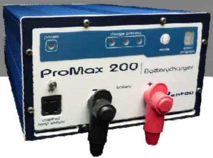
ProMax 200
Software V1.3.1
Mobile energy technics
INTRODUCTIE
2. Nalading (equalize) = T2
The voltages mentioned in this user manual are based on a 12V system. The voltages must be multiplied as follows: x2 for 24 Volt, x3 for 36 Volt and x4 for 48Volt. On the last pages you will find the technical specifications of the Promax 200.
The Promax 200 is a fully automatic battery charger and floatcharger in one and can be left connected to the mains power supply keeping the battery in a good condition. The microprocessor measures and checks the battery and charge process continuously, which results in a very safe and reliable charging process.
The ProMax contains different charging programs. By means of the 'mode' button on the front the charger the charging program is set easily. This way the charger can be adjusted optimally for each battery type and specific application.
You can use multiple powersources, like solar panels or a dynamo, together with the ProMax 200.
Important
Don't connect devices directly to the connection terminals on the battery charger.
FEATURES
The ProMax 200 contains a wide variety of features and protections to promote the usability and of course also to ensure that the charge process progresses extremely safe.
Reverse polarisation
Reverse polarisation means that the plus and minus connection wires are inadvertently reversed on the battery or on the charger. Reverse polarisation is indicated by an error indication. Disconnect, and connect the battery and the charger properly.
Short circuit (output)
The charger is protected from short circuit when no battery is connected, even in the presence of the mains voltage.
Batteries on the other hand cannot withstand short circuit!
You should for this reason never short circuit the battery. Never short circuit when the charger is connected to the battery, irrespective of whether the mains voltage is present.
When a battery is short circuited there is a danger that it will explode!!! The charger too will then incur serious damage.
Output voltage
The charger can only be activated if a battery has been connected to it. Without the presence of a battery no voltage readings will be measured.
Input voltage
The input of the charger is protected by means of a fuse. If the fuse needs to be replaced, a fuse with the same value must always be used for the replacement.
Current limitation
The charger incorporates a current limitation feature.
Charge time monitoring
When the charger is set for a 'stand alone' application, the duration of the charging process is monitored. If the boost and equalize phase together take more than 14 hours, the charging process will be stopped. This way it can be prevented a broken battery will be charged continuously. But with this feature it also can become clear that the charge current isn't in the correct proportion to the battery capacity (the battery can become damaged when the charge process takes too long).
Voltage drop compensation
The battery charger automatically compensates for the voltage drop over the connection cables. Because of this, it's possible that a voltage reading on the connection terminals will be higher than the set value. The correct current can therefore only be measured through the battery poles.
Soft start
The Promax 200 features a soft start, so that the charger has no influence on any power users which may be turned on (such as lighting for example). Because of this the correct charge level can only be indicated 3 min after start-up.
Temperature
The Promax 200 is protected against excess temperatures. At an internal temperature of more than 40^ the fan will turn on automatically. When the internal temperature is cooled down until 35^ , the fan also stops automatically. If the cooling of the fan isn't enough the charger will shut down totally. This thermal stop is indicated by an error indication. When the charger has cooled down until 100^ it will continue the charging process. How the temperature protective devices operate will depend strongly on the ambient temperature.
Level of protection
The indication for the degree of protection contains the character 'IP' (International Protection) followed by two or three digits that stipulates the conditions that it complies with. The first digit refers to the class of protection for density, the second digit to the fluid density and the last digit refers to the impact resistance. The Promax 200 can be assigned IP 205, which means:
2 = the charger is protected against solid particulate larger than 12mm.
0 = the charger is not protected against water/liquid etc.
5 = the charger can bear a n impact force of 2.00 Joule (2Nm) max.
Important
Protect the charger against moisture, pollution etc. This can be sucked in by the fan en will damage the charger internally. The cost for this repair is not covered by warranty.
SETTING THE CHARGING PROGRAM
The charging program can be set by pressing the 'mode' pushbutton on the front of the charger. Set the ProMax 200 to the correct program before mounting the case. The battery may be connected already but this is not a requirement.
The set up of the charger consists out of three phases.
→ First the application needs to be determined; there are 2 options: 'on-board' use or 'stand-alone' use (see explanation below).
→ In the second step the type of battery is determined.
→ As last step the determination whether a temperature sensor is present needs to be made.
The combination of these three adjustments determines the charging program.
If the charger is being set for the first time a '2' will appear in the display screen and the green led located under 'charge process' will come on. This charging program is the default factory setting.

Important
Under no circumstances must the charge program be set arbitrarily. This can lead to irreparable damage of the battery and any devices which may be connected. Since each battery type and -brands has its own charge requirements, the mentioned charging programs are purely suggestions. Always check if the recommended charging program matches the charging guides of your battery. See enclosures. If not, please contact your battery supplier for another suitable setting.
Used terms:
- On-board
There are users connected during the charging process. The charger will indirectly supply the present consumers. When charging a (partially) empty battery, the current draw of the consumers comes at the expense of the charge current for the battery.
- Stand-alone:
The opposite of on-board use. After discharging, the battery will be connected or the charger will be turned on. When the battery is going to be used again, the charger is disconnected or turned off. There are no users connected during the charging process.
- Heavy cyclic use
Heavy cyclic use means that the battery on a regular basis is discharged deeply ( >30% ) and then recharged. Because more sulphation occurs, some batteries require a different charging program.
Activating set-up mode:
→ Make sure you know the correct charger settings before you begin with the adjustment procedure (your application: on-board or stand-alone, which battery type you have and if a temperature sensor is present).
■ Connect the charger to the mains voltage supply.
- Press and hold down the 'mode' button and turn, at the same time, the charger on by way of the on/off button situated on the back of the device.
- Keep the button pressed down until a point lights up in the lower right corner of the display screen.
■ Continue with the steps appropriate for the particular application (on-board page 17, stand-alone page 18)
ON BOARD (users present during the charge process)
Put the charger in set-up mode, as described earlier.
A '0' will appear in the display screen. By way of pressing on the 'mode' button it is possible to switch between the green and the red led. Adjust the charger as per the green led (= factory setting).

After this wait for 10 seconds. A number will now appear in the display screen which indicates the charging program. By way of repeatedly pressing the 'mode' button it is possible to enter the correct charging program which corresponds to the battery type.
Battery type Suggested charging program
GEL, AGM ^1
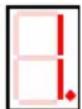
NAT (factory setting)

SEMI TRACTION
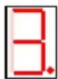
TRACTION

CALCIUM. AGM ^2 , SPIRAL

After this wait for 10 seconds.
A 't' will appear in the display screen. Now it is possible to determine if the optional temperature sensor has been connected. By way of pressing the 'mode' button it is once again possible to switch between the green and red led.
Temperature sensor present
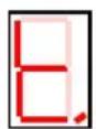


Set the LED to green.
Temperature sensor isn't present
(factory setting)




Set the LED to red.
STAND-ALONE (no users present during the charge process)
Put the charger in set-up mode, as described earlier.
A '0' will appear in the display screen. By way of pressing on the 'mode' button it is possible to switch between the green and the red led. Adjust the charger as per the red led.

After this wait for 10 seconds.
A number will now appear in the display screen which indicates the charging program. By way of repeatedly pressing the 'mode' button it is possible to enter the correct charging program which corresponds to the battery type.
Battery type
Suggested program
GEL, AGM ^1
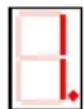
CALCIUM, AGM ^2 , SPIRAL
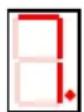
Heavy cyclic use?
(comp. phase on?

SEMI-TRACTION
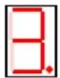
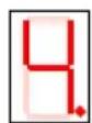
TRACTION


After this wait for 10 seconds.
A 't' will appear in the display screen. Now it is possible to determine if the optional temperature sensor has been connected. By way of pressing the 'mode' button it is once again possible to switch between the green and red led.
Temperature sensor present
Set

to green

Temperature sensor isn't present
(factory setting)
Set the LED



If after the adjustment of the temperature sensor the 'mode' button is not used for a duration of 10 seconds the charger will exit the set-up mode. If at that time a battery has already been connected then the charging process will start according to the selected program.
The selected settings will always briefly light up when turning on the charger. In the appendix you will find a brief list of all the charge settings.
If the mains voltage supply is removed, the last chosen charging program will remain in the memory of the battery charger. In the case the charger will next be utilized for a different function than the previous one then the proper adjustments will have to be made to the charging program.
INSTALLATION
The atmosphere
The battery should be charged in an area with adequate because it may emit explosive gases. Be sure that there is enough space around the charger. This is important for the air circulation, for cooling of the charger and release of gases emitted.
The Promax 200 may not be used outdoors.
Important
Do not charge when there is a fuel leak or fuel is evaporating.
Wire thickness
You can use the formula given below to determine the correct cable thickness. Keep the cables as short as possible.
$$ \text { Max. current } \quad x \quad \text { distance } \quad x \quad 0, 2 = \text { cable mmq } $$
$$ b a t t e r y - c h a r g e r $$
Example: ProMax 212-25 is connected on a distance of 2 meters.
$$ 2 5 (\text { current }) \times 2 (\text { meters }) \times 0, 2 = 1 0 \mathrm{mmq} $$
If the result is not a standard cable thickness, then use the nearest standard cable thickness.
Mounting
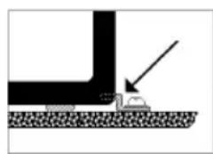
The charger can be mounted in different ways with the delivered mounting-material. For protection and stability, stick the self-adhesive rubber pads on the bottom of the case.
natural_image
Diagram showing a vehicle approaching a road with an arrow indicating direction (no text or symbols)Important
When the charger is to be used in an aluminium or steel ship/vessel, it must be insulated by suspension. That is, in order to avoid electrolysis, the casing of the charger may not be in contact with the ship. A possibility is to install a isolation transformer.
Connection
- Connect a red wire on the + bolt and a black wire on the - bolt of the charger by means of a terminal ring. Depending on the model charger, this is M6 or M8.
- Fasten firstly the other side of the red cable on the + pole of the battery (with an alligator clip, battery clamp or terminal ring). Repeat this with the black wire.
- The power plug can be put into a socket outlet and the charger can be switched on. The charging process will begin.
When you want to disconnect the charger from the battery, the charger must be switched off firstly.
Important
- The battery junction that isn't linked with the frame should be connected firstly. The other junction must be made with the frame.
- The connection between the charger and the battery must be made some distance from the fuel installation.
- Check whether the mains voltage of the voltage source is the same as the required voltage of the charger.
It is also very important that you observe the following procedures:
- always use the screw nuts and washers (brass nickel) included. When other materials are used there is a risk that the bolt will burn out of the print board.
- make sure that the wires make good contact between the charger and the battery. If this connection is weak, there is a chance that the bolts will burn out of the print board.
- do not tighten the screws more than necessary. If the screws are tightened too much the bolts may disconnect from the print board.
If the charger has a malfunction because these procedures are not observed, the warranty will lapse.
Advice
It is advisable to mount a fuse between the + pole of the battery and the + bolt of the charger. Always use a fuse that is heavier than the charge current.
CONNECTING A BATTERY ISOLATOR
You can charge/maintain two or three battery sets simultaneously by using a battery isolator. It is important to connect the D+ connector of the charger. If the D+ connector is not connected then the system will not work. Connect the D+ connection on the charger with the D+ connection on the battery isolator by means of a thin cable (+/-1.5mmq). In addition, mount a diode between the D+ of the dynamo and the D+ battery isolator. We advise to use the low-loss DB 180 (2 outputs) or the DB 270 (3 outputs).
IN USE
When turning on the charger the display will briefly indicate the adjusted charging setting by way of a number and one or more led's under 'charge process' will light up. At the start of the charging process the Promax 200 first checks the battery voltage. If the battery voltage is not correct then an error indicator will indicate this.
The charging process consists of 5 phases at most, depending on the dipswitch settings. The length of the charging time depends on the battery quality, battery capacity, depth of discharge and the current draw of any present users. Furthermore any faults could delay the process. A short description of each charging phase:
1. Boost = T1
Every charging session begins with this phase, whether the battery is full or not. The charging current is 100% and the voltage increases until the set voltage is reached. The boost charge always takes at least 30 minutes. As such, even if a full battery is connected this phase always takes 30 minutes.
During this phase the red LED under 'charging process' lights.
2. Equalize = T2
In this phase the charger keeps the charge voltage on the set value. Because the battery is filling up the charging current decreases. The point at which the following phase is entered depends on the charging program. However, this charge phase always has a duration of maximum 4 hours, without any thermal stops which may occur.
During this phase the yellow LED under 'charging process' lights.
3. Compensate = T3
This is a special and extra phase for breaking down the sulphates which build up when a battery is (deeply) discharged on a regular basis. The voltage can increase to 16Volt. As such, this phase is only used in 'stand alone' applications (no users present during the charging process). This phase isn't suitable for most sealed, maintenance free batteries.
The compensation phase lasts at most 4 hours, plus any thermal stops which may occur.
During this phase the yellow LED under 'charging process' blinks.
4. Float = T4
The battery is full and is maintained with a lower, stable voltage of 13.5Volt or 13.8Volt, depending on the charge setting. During this phase, the charger can still supply its maximum current without the charger going into the boost phase. Because of this the Promax 200 is capable of supplying other devices when used 'on board'. If the battery voltage drops below 12.65 Volt for a longer period of time, the charger automatically switches back to the boost phase (T1). During this phase the green LED under 'charging process' lights.
5. Jogging = T5
If, during float charging, the charging current is less than 10% for more than 24 hours, the charger switches over to jogging. This phase prevents a battery, which has been on float charge for a long time, from becoming "lazy". During this phase no charging current is delivered. If the battery voltage drops below 12.65 Volt the charger automatically switches back to the boost charge phase (T1).
During this phase the green LED under 'charging process' blinks.
Important
If you want to remove the charger from the battery, it's important that the charging process is always completely finished. As such, the charging process may only be stopped when the green LED from 'charge process' lights or blinks. If the charging process is interrupted before it is completed, the battery loses its charge and its acid balance.
When disconnecting the battery, at interruption of the mains voltage or when the charger is turned off, the current charging process will stop. When a battery is re-connected, the mains voltage is present again or when the charger is turned on again, in all cases a new charging process will start.
When a problem is detected at the start or during the charge process, a number will appear in the display which indicates a certain error. Consult the 'Charge Status' and 'Trouble Shooting' for the right actions.
CHARGE STATUS
| LED red | LED yellow LED | green | Error display | |||
| lights | links lights | blinks | ||||
| Boost X | ||||||
| Equalize X | ||||||
| Compensate X | ||||||
| Float X | ||||||
| Jogging X | ||||||
| Reverse polarisation or no battery present | 1 | |||||
| Battery voltage too low | 2 | |||||
| 14 hours limit | 3 | |||||
| Temperature sensor | 4 | |||||
| Battery sulphated | 5 | |||||
| Temp.sensor error | 6 | |||||
Consult "Trouble shooting" for the error messages
TROUBLE SHOOTING
Problem (Possible) cause Action
| Error 1(Error message 1 alternates with displaying the set charging program) | Reversed polarization of the cables. | Remove the connection and attach the cables correctly. |
| No battery voltage present. | Check the connection and the fuses between the battery and the charger. | |
| There is a battery isolator connected that blocks the battery voltage. | Use the D+ connection on the front of the charger. See chapter 'Connecting a battery isolator'. | |
| Error 2 | The battery has a voltage between 1.0 and 11.0Volt. | This indicator stays lighting for 5 minutes. Take no further action and wait for the charging process to complete.Warning! If the battery is frequently discharged too deeply, the battery will breakdown quickly. |
| Error 3 | The boost phase (T1) + the equalize phase (T2) is longer than 14 hours.The charging process has stopped. | Check whether the charger can deliver enough current for the battery.Check whether there are any devices on, which consume a lot of power, during charging.Change the charging program.Check the battery. |
| Error 4 | The charger is in a thermical stop. | The charging process will continue automatically when the charger has could down.- Try to place the charger in a environment that is as cool as possible.- Check whether the battery has sufficient ventilation. |
| Error 5 | Battery sulphated. | Monitor this error indication during the following charging sessions. If this error continues to occur, have the battery checked/replaced. |
| Error 6 | Temperature sensor broken. | Replace the temperature sensor |
| The charger is set for use of the temperature sensor, but the sensor isn't present. | Change the charging program (page 16-19). | |
| Charger doesn't work. No mains voltage. | - Measure the mains voltage. It should be higher than 180VAC (95VAC for 115VAC input). - Have the internal fuse checked by your dealer. | |
| The Power LED lights, but the charger doesn't work | Mains voltage to low. | Measure the mains voltage. It should be higher than 180VAC (95VAC for 115VAC input). |
| The charger gives the correct indication but the battery is not charging. The charger does not supply the correct voltage (and current). | The charger is busy with its soft start. | 3 minutes after switching o the charger, the correct charge level is indicated. |
| Charger doesn't deliver its maximum charging current | Mains voltage to low. | Measure the mains voltage. Below a voltage of 200VAC (100VAC for 115VAC input) the charger can't deliver its complete charging current. |
| Battery doesn't fill up, the red or yellow LED continues to burn. | The battery is defective | Measure the acid and replace the battery if necessary. |
| There are heavy consumers connected to the battery. | Turn off as many consumer as possible. | |
| Battery is too heavy for the charger | Ask your supplier for advice. | |
| The voltage you measure on the output terminals is too high | The charger automatically compensates for the voltage drop over the cables. | Measure the voltage on the battery terminals. |
ACCESSORIES
Temperature sensor BTC 100
The optional temperature sensor BTC 100 measures the temperature of the battery during the entire charging process. Depending on the temperature measured the end voltage is compensated. Important this compensation must be activated. See the chapter 'Setting the charge program'.
LCD-monitor PCM 100
With this monitor it is possible to follow the charging process remotely. The monitor displays details such as the battery voltage, charging current, charging phase and any errors which may occur.
T-Splitter
For connecting the PCM 100 and BTC 100 both, the t-splitter is needed.
MAINTENANCE
The charger doesn't need any specific maintenance. When cleaning the housing, use a (squeezed) dry cloth. Remove any filth and dust from the ventilation openings of the charger. Follow the instructions of the manufacturer when using and handling the battery. CAUTION! A battery contains corrosive sulphuric acid.
Important
- Check the charge status of battery charger on a regular basis.
- Check the cables and connection between the charger and battery regularly.
- Check the ventilation vents en fan on a regular basis.
- Check the degree of acidity of a non-maintenance free battery on a regular basis
WARRANTY AND SERVICE

The ProMax 200 chargers are marked with the Smart Value service label of Xenteq. This service label gives you additional advantages and certainties on service. Read more about this on our website
Before sending the charger back, always advice the Trouble Shooter and other information in this manual firstly. If a problem could have been solved by means of this manual, we are obligated to charge the repair/research costs.
In case of a malfunction, the charger can be brought back to your supplier or it can be send to the address on the back of this manual. The charger must be send prepaid. The ProMax 200 carries a five-year warranty from selling date. This warranty only covers the costs of parts and labour for the repair. The warranty period is only valid when the (copy)purchase ticket is handed over with the repaiThe warranty will lapse when a third party has attempted to repair the charger or when the ProMax 200 is not installed or used in accordance with the instructions. The only activities that may carried out yourselves is the replacement of the input fuseDo not attempt to repair the charger yourselves.
The manufacturer cannot be hold responsible for the (suggested) charge settings or any damage resulting from use of the Promax 200.
ALGEMEIN
natural_image
Diagram showing a mechanical setup with a tool and a block, no visible text or symbolsAchtung
EC DECLARATION OF CONFORMITY
This certifies that the following designated product
Product name: Type / model:
ProMax 200 Battery Charger
| ProMax 212-15 | ProMax 224-10 |
| ProMax 212-25 | ProMax 224-20 |
| ProMax 212-35 | ProMax 224-30 |
| ProMax 212-50 | ProMax 224-50 |
| ProMax 212-70 | ProMax 224-70 |
| ProMax 212-90 |
Complies with the requirements of the European Community Directive 73/23/EEC and 93/68/EEC for Low Voltage Directive and 89/336/EEC for Electro Magnetic Compatibility.
Used standards:
Assessment of compliance of the product with the requirements relating to electromagnetic compatibility was based on the following standards:
| EN61000-6-3 | EN61000-4-4 |
| EN61000-6-2 | EN61000-4-5 |
| EN61000-3-2 | EN61000-4-6 |
| EN61000-3-3 | EN61000-4-8 |
| EN61000-4-2 | EN61000-4-11 |
| EN61000-4-3 | ENV50204 |
Assessment of compliance of the product with the requirements relating to Low Voltage Directive was based on the following standards:
EN 61010
This is the result of the tests, that was carried out from the submitted type-sample of a product in conformity with the specification of the respective standards. The certificate holder has the right to fix the CE-mark for EMC and LVD on the product complying with the inspection sample.
Manufacturer name: Address: Country:
Xenteq BV Banmolen 14 5768 ET Meijel The Netherlands
Name and signature of the authorized person:
Place and date of issue
P.J.F. Linders

Meijel, 1 ^st January 2013
Xenteq BV
Banmolen 14
5768 ET Meijel (NL)
Tel. 0031-(0)774662067
Fax 0031-(0)774662845
www.xenteq.nl
info@xenteq.nl
- battery charger Profline
- ProMax 200
- INTRODUCTIE
- Nalading (equalize) = T2
- Important
- FEATURES
- Reverse polarisation
- Short circuit (output)
- Output voltage
- Input voltage
- Current limitation
- Charge time monitoring
- Voltage drop compensation
- Soft start
- Temperature
- Level of protection
- SETTING THE CHARGING PROGRAM
- Used terms:
- Activating set-up mode:
- ON BOARD (users present during the charge process)
- STAND-ALONE (no users present during the charge process)
- INSTALLATION
- The atmosphere
- Wire thickness
- Mounting
- Connection
- Advice
- CONNECTING A BATTERY ISOLATOR
- IN USE
- Boost = T1
- Equalize = T2
- Compensate = T3
- Float = T4
- Jogging = T5
- TROUBLE SHOOTING
- ACCESSORIES
- Temperature sensor BTC 100
- LCD-monitor PCM 100
- T-Splitter
- MAINTENANCE
- WARRANTY AND SERVICE
- ALGEMEIN
- Achtung
- EC DECLARATION OF CONFORMITY
- EN 61010
- Xenteq BV
Brand : Xenteq
Model : ProMax 200
Category : Charger