
AT-HDR-EX-70-2PS - Audio/video extender Atlona - Free user manual and instructions
Find the device manual for free AT-HDR-EX-70-2PS Atlona in PDF.


| Type | Audio/video extender (HDBaseT transmitter/receiver kit) |
| Model | AT-HDR-EX-70-2PS |
| Brand | Atlona |
| Video Support | 4K/UHD @ 60 Hz with 4:4:4 chroma sampling, HDR, up to 18 Gbps data rate |
| HDCP | HDCP 2.2 compliant |
| HDMI Specification | HDMI 2.0a |
| Maximum Distance (1080p) | 230 ft (70 m) over CAT6a/7 |
| Maximum Distance (4K HDR) | 130 ft (40 m) over CAT6a/7 |
| Compression | Visually lossless with no latency |
| Power Supply | Two 5 V DC power supplies (included) |
| Dimensions (Transmitter) | Approx. 4.5 x 2.6 x 1.0 in (114 x 66 x 25 mm) |
| Dimensions (Receiver) | Approx. 4.5 x 2.6 x 1.0 in (114 x 66 x 25 mm) |
| Weight (each unit) | Approx. 0.4 lb (0.18 kg) |
| Package Contents | 1 TX, 1 RX, 4 mounting brackets, 8 screws, 2 power supplies, installation guide |
| LED Indicators | POWER (solid green) and LINK (solid yellow = good, blinking = poor, off = no link) |
| Firmware Update | Via mini-USB port and AT-HDR-EX-70-2PS Analyzer software (Windows) |
| Cable Type Recommended | Solid core CAT5e/6/6a/7 (stranded not recommended) |
| Mounting | Surface mount with included brackets and screws |
| Warranty | 10-year limited product warranty |
| Maintenance | Clean with a soft, dry cloth; avoid liquids |
| Safety | Use only included power supplies; do not over-tighten locking connector |
Frequently Asked Questions - AT-HDR-EX-70-2PS Atlona
User questions about AT-HDR-EX-70-2PS Atlona
0 question about this device. Answer the ones you know or ask your own.
Ask a new question about this device
Download the instructions for your Audio/video extender in PDF format for free! Find your manual AT-HDR-EX-70-2PS - Atlona and take your electronic device back in hand. On this page are published all the documents necessary for the use of your device. AT-HDR-EX-70-2PS by Atlona.
USER MANUAL AT-HDR-EX-70-2PS Atlona
The Atlona AT-HDR-EX-70-2PS is an HDBaseT transmitter/receiver kit for high dynamic range (HDR) formats. The kit is HDCP 2.2 compliant and supports 4K/UHD video @ 60 Hz with 4:4:4 chroma sampling, as well as HDMI data rates up to 18 Gbps. The HDR-EX-70-2PS provides HDMI transmission up to 230 feet (70 meters) for 1080p video, and up to 130 feet (40 meters) for 4K HDR over CAT6a/7 cable. This extender kit features visually lossless compression with no latency to enable HDR and 4K/60 4:4:4 video signal extension over HDBaseT. The HDR-EX-70-2PS delivers a cost-effective solution for HDMI extension, with locally powered transmitter and receiver endpoints as well as surface mounting hardware for discreet installation.
The HDR-EX-70-2PS is ideal for residential applications with the latest as well as emerging 4K/UHD and HDR sources and displays. It is compatible with all video resolutions, audio formats, and color space formats supported in the HDMI 2.0a specification, plus the ability to pass metadata for HDR content. The HDR-EX-70-2PS includes Atlona's award-winning 10 year limited product warranty and customer support services, so that integrators can specify, purchase, and install with confidence.
Package Contents
1 x AT-HDR-EX-70-2PS-TX
1 x AT-HDR-EX-70-2PS-RX
4 x Mounting brackets
8 x Mounting screws
2 x 5 V DC power supplies
1 x Installation Guide

IMPORTANT: Visit http://www.atlona.com/product/AT-HDR-EX-70-2PS for the latest firmware updates and Installation Guide.
Panel Descriptions
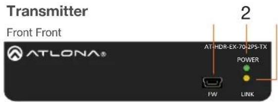
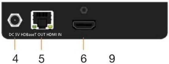
Rear Rear
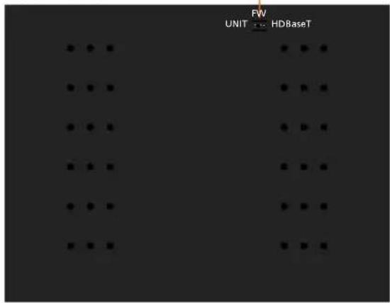
Bottom Bottom
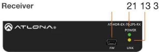
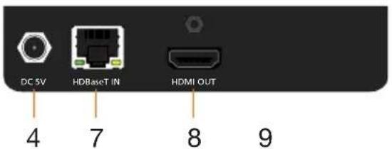
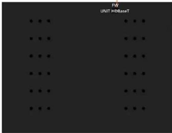
1 FW
Connect a mini-USB to USB-A type cable from this port to a computer, to update the firmware. Refer to Updating the Firmware, on page 5, for more information.
2 POWER
This LED indicator glows solid green when the unit is powered. Refer to LED Indicators, on page 4, for more information.
3 LINK
This LED indicator indicates the link status between the transmitter and the receiver. Refer to LED Indicators, on page 4, for more information.
4 DC 5V
Connect the included power supply to this power receptacle.
5 HDBaseT OUT
Connect an Ethernet cable from this port
to the HDBaseT IN port on the receiver.
6 HDMI IN
Connect an HDMI cable from this port to a UHD/HD source.
7 HDBaseT IN
Connect an Ethernet cable from this port to the HDBaseT OUT port on the transmitter.
8 HDMI OUT
Connect an HDMI cable from this port to an UHD/HD display.
9 FW (UNIT / HDBaseT)
Set this switch to the UNIT position to update the firmware. Refer to Updating the Firmware, on page 7, for more information. For normal operation or for HDBaseT cable testing, set to the HDBaseT position. Refer to Testing HDBaseT Signal Integrity, on page 5, for more information.
Installation
- Connect a UHD/HD source to the HDMI IN port on the AT-HDR-EX-70-2PS-TX.
- Connect a UHD/HD display to the HDMI OUT port on the AT-HDR-EX-70-2PS-RX.
- Connect an Ethernet cable, from the HDBaseT OUT port on the AT-HDR-EX-70-2PS-TX, to the HDBaseT IN port on the AT-HDR-EX-70-2PS-RX.
- Connect each of the included 5 V DC power supplies to the DC 5V locking power receptacles on both the AT-HDR-EX-70-2PS-TX and AT-HDR-EX-70-2PS-RX.

IMPORTANT: Do not over-tighten or apply high-torque devices to the locking connector. Doing so may damage the power receptacle and/or locking connector.
- Connect each of the power supplies to an available AC outlet.

IMPORTANT: The DIP switch, on the bottom of both the transmitter and receiver, must be set to HDBaseT mode for normal operation. If this is not the case, then disconnect power from the unit, set the DIP switch to HDBaseT mode, and then reconnect the power.
LED Indicators
The POWER and LINK LED indicator on the transmitter and receiver unit provides basic information on the current status of the AT-HDR-EX-70-2PS. The information in the table below applies to both the transmitter and receiver unit.
POWER Description
| Solid green Unit is powered. | |
| Off Unit is not powered. | ·Verify that the locking connector is securely fastened to the power receptacle.·Make sure that the power supply is connected to an active AC outlet. |
LINK Description
| Solid yellow The link integrity | between the transmitter and the receiver is good. |
| Blinking yellow Poor signal integrity between the transmitter and the receiver.Make sure that the Ethernet connection between the HD-BaseT IN port on the transmitter and the HDBaseT OUT port on the receiver is secure.The Ethernet cable may be compromised. Try using a different Ethernet cable. Make sure that the cable is solid core. Stranded or patch cables are not recommended. | |
| Off The link integrity between the transmitter and the receiver is compromised.Check the Ethernet cable between the HDBaseT IN port on the transmitter and the HDBaseT OUT port on the receiver. | |
Testing HDBaseT Signal Integrity
The AT-HDR-EX-70-2PS Analyzer is a free, downloadable software application that is used to test the signal integrity of HDBaseT cables. The software is available from Atlona.com, on the AT-HDR-EX-70-2PS product page.
Requirements
• AT-HDR-EX-70-2PS-TX / AT-HDR-EX-70-2PS-RX
• AT-HDR-EX-70-2PS Analyzer software
• Computer running Microsoft Windows®
• USB-A to mini-B cable
- Download and run the AT-HDR-EX-2PS Analyzer.exe file. The software comes with a ConnectorTool.dll file. The DLL file must exist in the same folder as the executable, in order for the software to run.
- Verify that the DIP switch, on the bottom of the unit, is set to the HDBaseT position, as shown below.
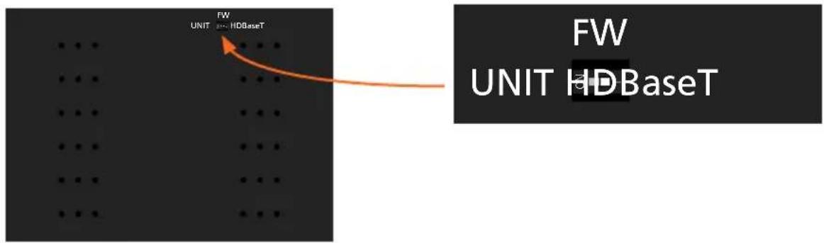
-
Reconnect power to both the transmitter and receiver. Make sure that a signal is passing between the transmitter and the receiver.
-
Set the DIP switch to the UNIT position.
-
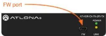
Connect a USB-A to USB mini-B cable from the computer to the FW port on either the transmitter or the receiver.
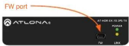
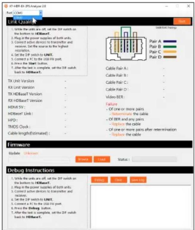
When performing an HDBaseT test, connecting to either the transmitter or receiver will provide the same results.
- Launch the AT-HDR-EX-70-2PS Analyzer software.
- Click the Start button.
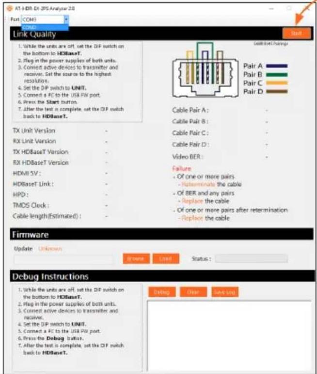
Start button
- If the HDBaseT link integrity is good, then all tests will display as "Pass".
-
If any part of the HDBaseT cable fails, then a numerical value, in decibels, will be displayed next to the associated pair, under the Signal Quality section. These values can be reported to Atlona Technical Support Engineers to help resolve possible issues.
-
After testing is complete, set the DIP switch on the bottom of the unit to the HDBaseT position.
Cable Recommendation Guidelines
Refer to the tables below for recommended cabling when using Altona products with HDBaseT. The green bars indicate the signal quality when using each type of cable. Higher-quality signals are represented by more bars.
Core Shielding CAT5e CAT6 CAT6a CAT7
| Solid UTP (unshielded) N/A | ||||
| STP (sheilded) | ||||
| Performance Rating (MHz) 350 500 600 800 | ||||

IMPORTANT: Stranded or patch cables are not recommended due to performance issues.
Cable* Max. Distance @ 4K Max. Distance @ 1080p
| CAT5e / CAT6 | 115 feet (35 meters) | 200 feet (60 meters) |
| CAT6a / CAT7 | 130 feet (40 meters) | 230 feet (70 meters) |
*Atlona recommends TIA/EIA 568-B termination for optimal performance.
Updating the Firmware
The follow procedure outlines the firmware update procedure and applies to both the transmitter and receiver. Both the AT-HDR-EX-70-2PS firmware and analyzer software will be required for this process and are available from Atlona.com on the AT-HDR-EX-70-2PS product web page.
Requirements
• AT-HDR-EX-70-2PS-TX / AT-HDR-EX-70-2PS-RX
• AT-HDR-EX-70-2PS Analyzer software
- Firmware file
• Computer running Microsoft Windows®
• USB-A to mini-B cable
- Download and run the AT-HDR-EX-2PS Analyzer.exe file. The software comes with a ConnectorTool.dll file. The DLL file must reside in the same folder as the executable, in order for the software to run.
- Disconnect power from the unit.
- Set the DIP switch, on the bottom of the unit, to the UNIT position, as shown below.

-
Connect a USB-A to USB mini-B cable from the computer to the FW port on the AT-HDR-EX-70-2PS.
-
Launch the AT-HDR-EX-70-2PS Analyzer software.
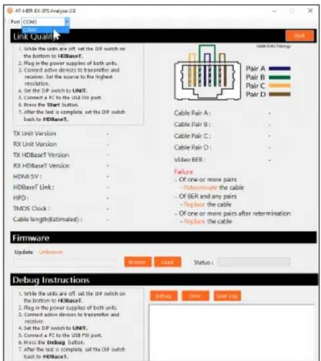
- Select the proper COM port from the drop-down list, in the top-left corner of the software screen.
- Extract the firmware, from the archive file, to the Windows desktop or other folder.
- Click the Browse button within the AT-HDR-EX-70-2PS Analyzer software. The Open file dialog box will be displayed.
- Select the proper firmware file from the location specified in step 6:
Transmitter: HDR-2PS-TX_[version].hex
Receiver: HDR-2PS-RX_[version].hex
- Click the Open button on the dialog box.
- Click the Load button, within the AT-HDR-EX-70-2PS Analyzer software, to begin the firmware update procedure. During the update process, the current progress will be displayed in the progress bar.
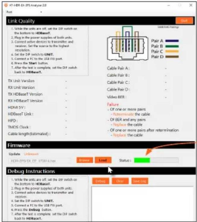
Progress bar
- Once the upgrade process is complete, set the DIP switch, on the bottom of the unit, to the HDBaseT position.

IMPORTANT: The DIP switch, on the bottom of both the transmitter and receiver, must be set to HDBaseT mode before reconnecting the power in order to resume normal operation.
- Reconnect the power supply to the unit.
- Repeat steps 2 though 13 for the other unit(s).
Mounting Instructions
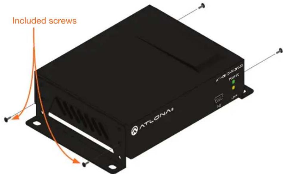
The AT-HDR-EX-70-2PS encoder includes two mounting brackets and four mounting screws, which can be used to attach the unit to any flat surface.
-
Position one of the mounting brackets, as shown below, aligning the holes on the side of the enclosure with one set of holes on the mounting bracket.
-
Use the enclosure screws to secure the mounting bracket to the enclosure.
-
Repeat the above steps to attach the second mounting bracket to the opposite side of the unit.
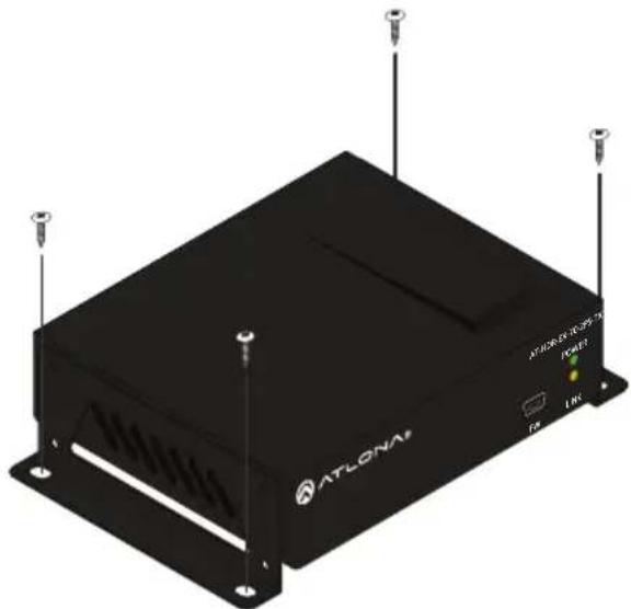
- Mount the unit using the oval-shaped holes, on each mounting bracket. If using a drywall surface, a #6 drywall screw is recommended.
natural_image
Black ATLONIA ATLONIA processor with visible power, I/O ports, and antenna (no text or symbols on body)
NOTE: Mounting brackets can also be inverted to mount the unit under a table or other flat surface.
Atlona, Inc. ("Atlona") Limited Product Warranty
Coverage
Atlona warrants its products will substantially perform to their published specifications and will be free from defects in materials and workmanship under normal use, conditions and service.
Under its Limited Product Warranty, Atlona, at its sole discretion, will either:
- repair or facilitate the repair of defective products within a reasonable period of time, restore products to their proper operating condition and return defective products free of any charge for necessary parts, labor and shipping.
OR
- replace and return, free of charge, any defective products with direct replacement or with similar products deemed by Atlona to perform substantially the same function as the original products.
OR
- refund the pro-rated value based on the remaining term of the warranty period, not to exceed MSRP, in cases where products are beyond repair and/or no direct or substantially similar replacement products exist.
Repair, replacement or refund of Atlona products is the purchaser's exclusive remedy and Atlona liability does not extend to any other damages, incidental, consequential or otherwise.
This Limited Product Warranty extends to the original end-user purchaser of Atlona products and is non-transferrable to any subsequent purchaser(s) or owner(s) of these products.
Coverage Periods
Atlona Limited Product Warranty Period begins on the date of purchase by the end-purchaser. The date contained on the end-purchaser 's sales or delivery receipt is the proof purchase date.
Limited Product Warranty Terms – New Products
- 10 years from proof of purchase date for hardware/electronics products purchased on or after June 1, 2013.
- 3 years from proof of purchase date for hardware/electronics products purchased before June 1, 2013.
• Lifetime Limited Product Warranty for all cable products.
Limited Product Warranty Terms – Refurbished (B-Stock) Products and Discontinued Products
- 3 years from proof of purchase date for all Refurbished (B-Stock) and Discontinued hardware and electronic products purchased on or after June 1, 2013.
Atlona, Inc. ("Atlona") Limited Product Warranty Cont.
Remedy
Atlona recommends that end-purchasers contact their authorized Atlona dealer or reseller from whom they purchased their products. Atlona can also be contacted directly. Visit www.atlona.com for Atlona's contact information and hours of operation. Atlona requires that a dated sales or delivery receipt from an authorized dealer, reseller or end-purchaser is provided before Atlona extends its warranty services. Additionally, a return merchandise authorization (RMA) and/or case number, is required to be obtained from Atlona in advance of returns.
Atlona requires that products returned are properly packed, preferably in the original carton, for shipping. Cartons not bearing a return authorization or case number will be refused. Atlona, at its sole discretion, reserves the right to reject any products received without advanced authorization. Authorizations can be requested by calling 1-877-536-3976 (US toll free) or 1-408-962-0515 (US/international) or via Atlona's website at www.atlona.com.
Exclusions
This Limited Product Warranty excludes:
- Damage, deterioration or malfunction caused by any alteration, modification, improper use, neglect, improper packaging or shipping (such claims must be presented to the carrier), lightning, power surges, or other acts of nature.
- Damage, deterioration or malfunction resulting from the installation or removal of this product from any installation, any unauthorized tampering with this product, any repairs attempted by anyone unauthorized by Atlona to make such repairs, or any other cause which does not relate directly to a defect in materials and/or workmanship of this product.
- Equipment enclosures, cables, power supplies, batteries, LCD displays, and any accessories used in conjunction with the product(s).
- Products purchased from unauthorized distributors, dealers, resellers, auction websites and similar unauthorized channels of distribution.
Disclaimers
This Limited Product Warranty does not imply that the electronic components contained within Atlona's products will not become obsolete nor does it imply Atlona products or their electronic components will remain compatible with any other current product, technology or any future products or technologies in which Atlona's products may be used in conjunction with. Atlona, at its sole discretion, reserves the right not to extend its warranty offering in instances arising outside its normal course of business including, but not limited to, damage inflicted to its products from acts of god.
Limitation on Liability
The maximum liability of Atlona under this limited product warranty shall not exceed the original Atlona MSRP for its products. To the maximum extent permitted by law, Atlona is not responsible for the direct, special, incidental or consequential damages resulting from any breach of warranty or condition, or under any other legal theory. Some countries, districts or states do not allow the exclusion or limitation of relief, special, incidental, consequential or indirect damages, or the limitation of liability to specified amounts, so the above limitations or exclusions may not apply to you.
Atlona, Inc. ("Atlona") Limited Product Warranty Cont.
Exclusive Remedy
To the maximum extent permitted by law, this limited product warranty and the remedies set forth above are exclusive and in lieu of all other warranties, remedies and conditions, whether oral or written, express or implied. To the maximum extent permitted by law, Atlona specifically disclaims all implied warranties, including, without limitation, warranties of merchantability and fitness for a particular purpose. If Atlona cannot lawfully disclaim or exclude implied warranties under applicable law, then all implied warranties covering its products including warranties of merchantability and fitness for a particular purpose, shall provide to its products under applicable law. If any product to which this limited warranty applies is a “Consumer Product” under the Magnuson-Moss Warranty Act (15 U.S.C.A. §2301, ET SEQ.) or other applicable law, the foregoing disclaimer of implied warranties shall not apply, and all implied warranties on its products, including warranties of merchantability and fitness for the particular purpose, shall apply as provided under applicable law.
Other Conditions
Atlona's Limited Product Warranty offering gives legal rights, and other rights may apply and vary from country to country or state to state. This limited warranty is void if (i) the label bearing the serial number of products have been removed or defaced, (ii) products are not purchased from an authorized Atlona dealer or reseller. A comprehensive list of Atlona's authorized distributors, dealers and resellers can be found at www.atlona.com.
- Package Contents
- FW
- POWER
- LINK
- DC 5V
- HDBaseT OUT
- HDMI IN
- HDBaseT IN
- HDMI OUT
- FW (UNIT / HDBaseT)
- Installation
- LED Indicators
- Testing HDBaseT Signal Integrity
- Requirements
- Start button
- Cable Recommendation Guidelines
- Updating the Firmware
- Mounting Instructions
- Atlona, Inc. ("Atlona") Limited Product Warranty
- Coverage
- OR
- Coverage Periods
- Limited Product Warranty Terms – New Products
- Limited Product Warranty Terms – Refurbished (B-Stock) Products and Discontinued Products
- Atlona, Inc. ("Atlona") Limited Product Warranty Cont.
- Remedy
- Exclusions
- Disclaimers
- Limitation on Liability
- Exclusive Remedy
- Other Conditions
Brand : Atlona
Model : AT-HDR-EX-70-2PS
Category : Audio/video extender