/UA — Cooker — Mode d'emploi PDF")
KN1G21S(W)/UA - Cooker INDESIT - Free user manual and instructions
Find the device manual for free KN1G21S(W)/UA INDESIT in PDF.

| Product type | Freestanding gas cooker with oven |
| Brand | Indesit |
| Model | KN1G21S(W)/UA |
| Oven dimensions (HxWxD) | 34 x 39 x 44 cm |
| Oven volume | 58 litres |
| Hob burners | 4 gas burners (Fast, Semi-Fast, Auxiliary, Auxiliary) |
| Oven burner | Gas, with thermostat (140°C - 250°C) |
| Grill burner | Gas, 2.30 kW |
| Rotisserie | Available (on selected models) |
| Timer | Mechanical timer with buzzer (on selected models) |
| Power supply voltage | 230 V ~ 50 Hz |
| Gas types | LPG (Butane/Propane) and Natural Gas (Methane) |
| Gas connection | Flexible rubber hose (max 1.5 m) or stainless steel pipe (max 2 m) |
| Ignition | Electronic ignition (button or built-in knob) or manual with lighter |
| Flame failure safety device | Yes on selected burners and oven |
| Oven light | 25 W, E14 cap |
| Lower storage compartment | Yes, with heat protection shield |
| Adjustable feet | Yes, for levelling |
| Glass cover | Available on selected models |
| Cleaning | Removable hob parts, enamel oven interior, door glass with non-abrasive products |
| Safety | Anti-tilt? Not mentioned, but oven door must not be used as shelf |
| Certifications | CE, Low Voltage Directive, EMC, Gas Appliance Directive |
Frequently Asked Questions - KN1G21S(W)/UA INDESIT
User questions about KN1G21S(W)/UA INDESIT
0 question about this device. Answer the ones you know or ask your own.
Ask a new question about this device
Download the instructions for your Cooker in PDF format for free! Find your manual KN1G21S(W)/UA - INDESIT and take your electronic device back in hand. On this page are published all the documents necessary for the use of your device. KN1G21S(W)/UA by INDESIT.
USER MANUAL KN1G21S(W)/UA INDESIT
Operating Instructions COOKER AND OVEN
Contents
Operating Instructions, 1
Description of the appliance-Overall view,2
Description of the appliance-Control Panel,3
Installation,4
Start-up and use,8
Precautions and tips, 11
Care and maintenance, 12
Assistance,12
RS
РусскийРусский
Description of the appliance
Overall view
1.Hob burner
2.Hob Grid
- Control panel
4.Sliding grill rack
5.DRIPPING pan
6.Adjustable foot
- Containment surface for spills
8.GUIDE RAILS for the sliding racks
9.position 5
10.position 4
11.position 3
12.position 2
13.position 1
- Glass Cover *(Available only on certain models)
RS
Описание изделия
Общий вид
1 Газовые горелки
Description of the appliance Control panel
- GAS BURNER IGNITION button*
2.TIMER knob*
3.OVEN AND GRILL CONTROL knob
4.OVEN LIGHT / ROTISSERIE button*
5.Hob BURNER control knob
*Available only on certain models
RS
! Before operating your new appliance please read this instruction booklet carefully. It contains important information concerning the safe installation and operation of the appliance.
! Please keep these operating instructions for future reference. Make sure that the instructions are kept with the appliance if it is sold, given away or moved.
! The appliance must be installed by a qualified professional according to the instructions provided.
! Any necessary adjustment or maintenance must be performed after the cooker has been disconnected from the electricity supply.
! We recommend cleaning the oven before using it for the first time, following the instructions provided in the "Care and maintenance" section.
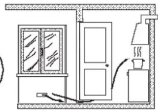
Room ventilation
The appliance may only be installed in permanently-ventilated rooms, according to current national legislation. The room in which the appliance is installed must be ventilated adequately so as to provide as much air as is needed by the normal gas combustion process (the flow of air must not be lower than 2 m^3/h per kW of installed power).
The air inlets, protected by grilles, should have a duct with an inner cross section of at least 100 cm^2 and should be positioned so that they are not liable to even partial obstruction (see figure A).
These inlets should be enlarged by 100% - with a minimum of 200 cm ^2 - whenever the surface of the hob is not equipped with a flame failure safety device. When the flow of air is provided in an indirect manner from adjacent rooms (see figure B), provided that these are not communal parts of a building, areas with increased fire hazards or bedrooms, the inlets should be fitted with a ventilation duct leading outside as described above.
A
Ventilation opening for
comburent air
Adjacent room Room requiring
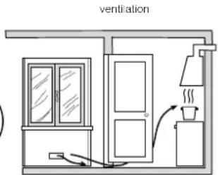
Increase in the gap between the door and the flooring
! After prolonged use of the appliance, it is advisable to open a window or increase the speed of any fans used.
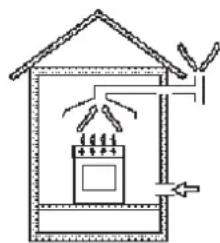
Disposing of combustion fumes
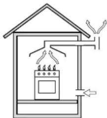
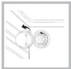
The disposal of combustion fumes should be guaranteed using a hood connected to a safe and efficient natural suction chimney, or using an electric fan that begins to operate automatically every time the appliance is switched on (see figure).
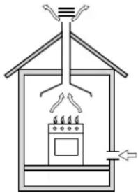
natural_image
Simple line drawing of a house interior with a stove and roof, no text or symbols presentFumes channelled straight outside
natural_image
Simple line drawing of a house interior with a stove, roof, and ventilation system (no text or symbols)Fumes channelled through a chimney or branched flue system reserved for cooking appliances)
! The liquefied petroleum gases are heavier than air and collect by the floor, therefore all rooms containing LPG cylinders must have openings leading outside so that any leaked gas can escape easily.
LPG cylinders, therefore, whether partially or completely full, must not be installed or stored in rooms or storage areas that are below ground level (cellars, etc.). Only the cylinder being used should be stored in the room; this should also be kept well away from sources of heat (ovens, chimneys, stoves) that may cause the temperature of the cylinder to rise above 50°C.
Positioning and levelling
! It is possible to install the appliance alongside cupboards whose height does not exceed that of the hob surface.
! Make sure that the wall in contact with the back of the appliance is made from a non-flammable, heat-resistant material (T 90°C).
To install the appliance correctly:
- Place it in the kitchen, dining room or the bed-sit (not in the bathroom).
- If the top of the hob is higher than the cupboards, the appliance must be installed at least 200 mm away from them.
- If the cooker is installed underneath a wall cabinet, there must be a minimum distance of 420 mm between this cabinet and the top of the hob. This distance should be increased to 700 mm if the wall cabinets are flammable (see figure).
- Do not position blinds behind the cooker or less than 200 mm away from its sides.
- Any hoods must be installed according to the
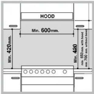
instructions listed in the relevant operating manual.
natural_image
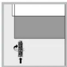
Simple diagram with a gray rectangle and a small black arrow pointing downward (no text or symbols)Levelling
If it is necessary to level the appliance, screw the adjustable feet into the places provided on each corner of the base of the cooker (see figure).
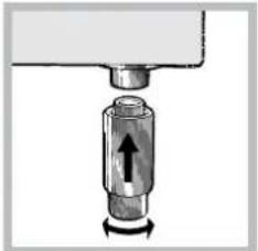
natural_image
Mechanical component diagram showing a cylindrical assembly with an arrow indicating force direction (no text or symbols)The legs* fit into the slots on the underside of the base of the cooker.
* Only available in certain models
Electrical connection
Install a standardised plug corresponding to the load indicated on the appliance data plate (see Technical data table).
The appliance must be directly connected to the mains using an omnipolar circuit-breaker with a minimum contact opening of 3 mm installed between the appliance and the mains. The circuit-breaker must be suitable for the charge indicated and must comply with NFC 15-100 regulations (the earthing wire must not be interrupted by the circuit-breaker). The supply cable must be positioned so that it does not come into contact with temperatures higher than 50°C at any point.
Before connecting the appliance to the power supply, make sure that:
- The appliance is earthed and the plug is compliant with the law.
- The socket can withstand the maximum power of the appliance, which is indicated by the data plate.
- The voltage is in the range between the values indicated on the data plate.
- The socket is compatible with the plug of the appliance. If the socket is incompatible with the plug, ask an authorised technician to replace it. Do not use extension cords or multiple sockets.
! Once the appliance has been installed, the power supply cable and the electrical socket must be easily accessible.
! The cable must not be bent or compressed.
! The cable must be checked regularly and replaced by authorised technicians only.
! The manufacturer declines any liability should these safety measures not be observed.
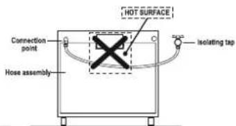
Gas connection
Connection to the gas network or to the gas cylinder may be carried out using a flexible rubber or steel hose, in accordance with current national legislation and after making sure that the appliance is suited to the type of gas with which it will be supplied (see the rating sticker on the cover: if this is not the case see below). When using liquid gas from a cylinder, install a pressure regulator which complies with current national regulations. To make connection easier, the gas supply may be turned sideways*: reverse the position of the hose holder with that of the cap and replace the gasket that is supplied with the appliance.
! Check that the pressure of the gas supply is consistent with the values indicated in the Table of burner and nozzle specifications (see below). This will ensure the safe operation and durability of your appliance while maintaining efficient energy consumption.
Gas connection using a flexible rubber hose
Make sure that the hose complies with current national legislation. The internal diameter of the hose must measure: 8 mm for liquid gas supply; 13 mm for methane gas supply.
Once the connection has been performed, make sure that the hose:
- Does not come into contact with any parts that reach temperatures of over 50°C.
- Is not subject to any pulling or twisting forces and that it is not kinked or bent.
- Does not come into contact with blades, sharp corners or moving parts and that it is not compressed.
- Is easy to inspect along its whole length so that its condition may be checked.
• Is shorter than 1500 mm. - Fits firmly into place at both ends, where it will be fixed using clamps that comply with current regulations.
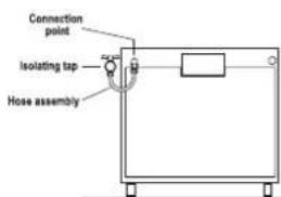
! If one or more of these conditions is not fulfilled or if the cooker must be installed according to the conditions listed for class 2 - subclass 1 appliances (installed between two cupboards), the flexible steel hose must be used instead (see below).
GB
Connecting a flexible jointless stainless steel pipe to a threaded attachment
Make sure that the hose and gaskets comply with current national legislation.
To begin using the hose, remove the hose holder on the appliance (the gas supply inlet on the appliance is a cylindrical threaded 1/2 gas male attachment).
! Perform the connection in such a way that the hose length does not exceed a maximum of 2 metres, making sure that the hose is not compressed and does not come into contact with moving parts.
Checking the connection for leaks
When the installation process is complete, check the hose fittings for leaks using a soapy solution. Never use a flame.
Adapting to different types of gas
It is possible to adapt the appliance to a type of gas other than the default type (this is indicated on the rating label on the cover).
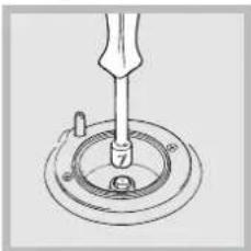
Adapting the hob
Replacing the nozzles for the hob burners:
- Remove the hob grids and slide the burners off their seats.
- Unscrew the nozzles using a 7 mm socket spanner (see figure), and replace them with nozzles suited to the new type of gas(see Burner and nozzle specifications table).
natural_image
Technical line drawing of a mechanical assembly with a tool inserted into a circular component (no text or symbols)- Replace all the components by following the above instructions in reverse.
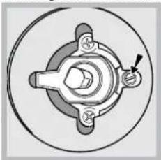
Adjusting the hob burners' minimum setting:
-
Turn the tap to the minimum position.
-
Remove the knob and adjust the regulatory screw, which is positioned inside or next to the tap pin, until the flame is small but steady.
! If the appliance is connected to a liquid gas supply, the regulatory screw must be fastened as tightly as possible. - While the burner is alight, quickly change the position of the knob from minimum to maximum and vice versa several times, checking that the flame is not extinguished.
! The hob burners do not require primary air adjustment.
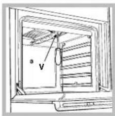
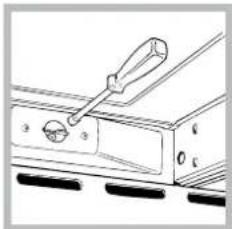
Adapting the oven
Replacing the oven burner nozzle:
- Remove the oven compartment.
- Slide out the protection panel A (see diagram).
- Remove the oven burner after unscrewing the screws V (see figure).
The whole operation will be made easier if the oven door is removed.
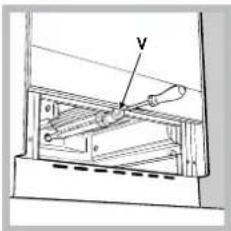
- Unscrew the nozzle using a special nozzle socket spanner (see figure) or with a 7 mm socket spanner, and replace it with a new nozzle that is suited to the new type of gas (see Burner and nozzle specifications table).
natural_image
Line drawing of a mechanical switch or lever assembly (no text or symbols)Adjusting the gas oven burner's minimum setting:
- Light the burner (see Start-up and Use).
- Turn the knob to the minimum position (MIN) after it has been in the maximum position (MAX) for approximately 10 minutes.
- Remove the knob.
- Tighten or loosen the adjustment screws on the outside of the thermostat pin (see figure) until the flame is small but steady.
! If the appliance is connected to liquid gas, the adjustment screw must be fastened as tightly as possible.
5. Turn the knob from the MAX position to the MIN position quickly or open and shut the oven door, making sure that the burner is not extinguished.
natural_image
Mechanical component diagram showing a central hub with four arms and a pointer indicating a specific section (no text or labels present)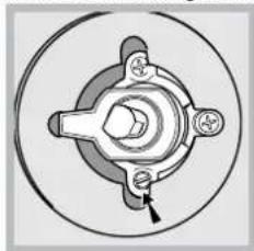
natural_image
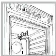
Mechanical component diagram showing a central hub with three arms and a central shaft, no text or symbols present.Adapting the grill
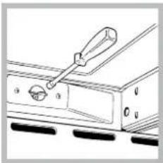
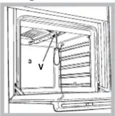
Replacing the grill burner nozzle:
- Remove the oven burner after loosening screw V (see figure).
- Unscrew the grill burner nozzle using a special nozzle socket spanner (see fi gure) or preferably with a 7 mm socket spanner, and replace it with a new nozzle that is suited to the new type of gas (see Burner and nozzle specifications table).
natural_image
Line drawing of a cabinet interior with doors and shelves, no text or symbols present! Be careful of the spark plug wires and the thermocouple tubes.
! The oven and grill burners do not require primary air adjustment.
! After adjusting the appliance so it may be used with a different type of gas, replace the old rating label with a new one that corresponds to the new type of gas (these labels are available from Authorised Technical Assistance Centres).
! Should the gas pressure used be different (or vary slightly) from the recommended pressure, a suitable pressure regulator must be fitted to the inlet hose in accordance with current national regulations relating to "regulators for channelled gas".
We recommend cleaning the oven before using it for the first time, following the instructions provided in the „Care and maintenance” section.
| TECHNICAL DATA | |
| Oven dimensions (HxWxD) | 34x39x44 cm |
| Volume | 58 l |
| Useful measurements relating to the oven compartment | width 42 cm depth 44 cm height 18 cm |
| Power supply voltage and frequency | see data plate |
| Burners | may be adapted for use with any type of gas shown on the data plate, which is located inside the flap or, after the oven compartment has been opened, on the left-hand wall inside the oven. |
 | EC Directives: 2006/95/EC dated 12/12/06 (Low Voltage) and subsequent amendments - 2004/108/EC dated 15/12/04 (Electromagnetic Compatibility) and subsequent amendments - 2009/142/EC dated 30/11/09 (Gas) and subsequent amendments - 93/68/EEC dated 22/07/93 and subsequent amendments - 2002/96/EC. 1275/2008 (Stand-by/ Off mode) |
Table of burner and nozzle specifications
| Table 1 Liquid Gas Natural Gas | |||||||||||
| Burner Diameter(mm) | Thermal PowerkW (p.c.s. *)Nominal Reduced (mm) (mm) **** (mm) (mm) | By-Pass1/100 | Nozzle1/100 | Flow*g/h | Nozzle1/100 | Flow*l/h | Nozzle1/100 | Flow*l/h | |||
| Fast(Large)(R) | 100 | 3.00 | 0.7 | 41 | 86 | 218 | 214 | 116 | 286 | 143 | 286 |
| Semi Fast(Medium)(S) | 75 | 1.90 | 0.4 | 30 | 70 | 138 | 136 | 106 | 181 | 118 | 181 |
| Auxiliary(Small)(A) | 55 | 1.00 | 0.4 | 30 | 50 | 73 | 71 | 79 | 95 | 80 | 95 |
| Oven | - | 2.80 | 1.0 | 46 | 80 | 204 | 200 | 119 | 267 | 132 | 257 |
| Grill | - | 2.30 | - | - | 75 | 167 | 164 | 114 | 219 | 139 | 227 |
| SupplyPressures | Nominal (mbar)Minimum (mbar)Maximum (mbar) | 28-30 | 37 | 20 | 13 | ||||||
| 20 | 25 | 17 | 6,5 | ||||||||
| 35 | 45 | 25 | 18 | ||||||||
* At 15°C and 1013 mbar- dry gas
** Propane P.C.S. = 50,37 MJ/Kg
*** Butane P.C.S. = 49,47 MJ/Kg
Natural P.C.S. = 37,78 MJ/m³
KN1G21/UA
KN1G21S/UA
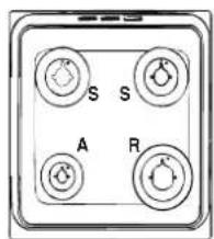
Using the hob
Lighting the burners
For each BURNER knob there is a complete ring showing the strength of the flame for the relevant burner.
To light one of the burners on the hob:
- Bring a flame or gas lighter close to the burner.
- Press the BURNER knob and turn it in an anticlockwise direction so that it is pointing to the maximum flame setting ⬆.
- Adjust the intensity of the flame to the desired level by turning the BURNER knob in an anticlockwise direction. This may be the minimum setting ⬆, the maximum setting ⬆ or any position in between the two.
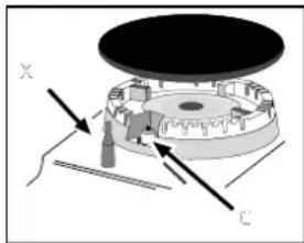
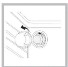
If the appliance is fitted with an electronic lighting device* (see figure), press the ignition button, marked
natural_image
Mechanical assembly diagram showing a rotating component with labeled axes X and C (no text or symbols beyond labels)with the symbol ☆, then hold the BURNER knob down and turn it in an anticlockwise direction, towards the maximum flame setting, until the burner is lit.
Several models are equipped with an ignition device
which is built into the knob; in this case the electronic ignition device* is present (C) but the ignition button is not. Simply press the BURNER knob and turn it in an anticlockwise direction so that it is pointing to the maximum flame setting, until the burner is lit. The burner may be extinguished when the knob is released. If this occurs, repeat the operation, holding the knob down for a longer period of time.
! If the flame is accidentally extinguished, switch off the burner and wait for at least 1 minute before attempting to relight it.
If the appliance is equipped with a flame failure safety device*(X), press and hold the BURNER knob for approximately 2-3 seconds to keep the flame alight and to activate the device.
To switch the burner off, turn the knob until it reaches the stop position •.
WARNING! The glass lid can break For the burners to work in the most in if it is heated up. Turn off all the efficient way possible and to save burners and the electric plates before closing the lid. *Applies to the models with glass cover only.
Practical advice on using the burners
on the amount of gas consumed, it is recommended that only pans that have a lid and a flat base are used. They should also be suited to the size of the burner.
| Burner Cookware diameter (cm) | |
| Fast (R) 24 - 26 | |
| Semi Fast (S) 16 - 20 | |
| Auxiliary (A) 10 - 14 | |
To identify the type of burner, please refer to the diagrams contained in the "Burner and nozzle specifications".
Using the oven
! The first time you use your appliance, heat the empty oven with its door closed at its maximum temperature for at least half an hour. Ensure that the room is well ventilated before switching the oven off and opening the oven door. The appliance may emit a slightly unpleasant odour caused by protective substances used during the manufacturing process burning away.
! Before operating the product, remove all plastic film from the sides of the appliance.
! Never put objects directly on the bottom of the oven; this will avoid the enamel coating being damaged. Only use position 1 in the oven when cooking with the rotisserie spit.
Lighting the oven
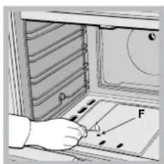
To light the oven burner, bring a flame or gas lighter close to opening F (see figure) and press the OVEN control knob while turning it in an anticlockwise direction until it reaches the MAX position.
If, after 15 seconds, the burner is still not alight, release the knob, open the oven door and wait for at least 1 minute before trying to light it again.
! The oven is fitted with a safety device and it is therefore necessary to hold the OVEN
control knob down for approximately 6 seconds.
! If the flame is accidentally extinguished, switch off the burner and wait for at least 1 minute before attempting to relight the oven.
* Only available in certain models.
Adjusting the temperature
To set the desired cooking temperature, turn the OVEN control knob in an anticlockwise direction. Temperatures are displayed on the control panel and may vary between MIN (140°C) and MAX (250°C). Once the set temperature has been reached, the oven will keep it constant by using its thermostat.
Grill
To light the grill, bring a flame or gas lighter close to the burner and press the OVEN control knob while turning it in a clockwise direction until it reaches the position. The grill enables the surface of food to be browned evenly and is particularly suitable for roast dishes, schnitzel and sausages. Place the rack in position 4 or 5 and the dripping pan in position 1 to collect fat and prevent the formation of smoke.
! The grill is fitted with a safety device and it is therefore necessary to hold the OVEN control knob down for approximately 6 seconds.
! If the flame is accidentally extinguished, switch off the burner and wait for at least 1 minute before attempting to relight the grill.
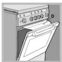
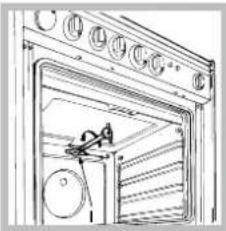
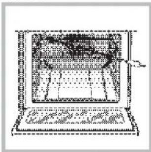
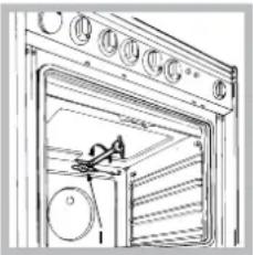
! When using the grill, leave the oven door ajar, positioning the deflector D between the door and the control panel (see figure) in order to prevent the knobs from overheating.
natural_image
Diagram of a refrigerator interior with a hand pulling a cable (no text or symbols)Turnspit\*
To operate the rotisserie (see diagram) proceed as follows: 1. Place the dripping pan in position 1.
- Place the rotisserie support in position 4 and insert the spit in the hole provided on the back panel of the oven.
- Acitvate the function by pressing the TURNSPIT button.
Timer\*
To activate the Timer proceed as follows:
- Turn the TIMER knob in a clockwise direction for almost one complete revolution to set the buzzer.
- Turn the TIMER knob in an anticlockwise direction ○ to set the desired length of time.
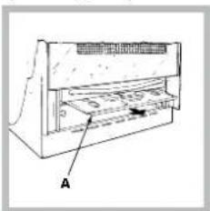
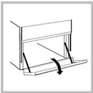
Lower compartment\*
There is a compartment underneath the oven that may be used to store oven accessories or deep dishes. To open the door pull it downwards (see figure).
natural_image
Simple line drawing of a mechanical assembly with a lever and base (no text or symbols)! The internal surfaces of the compartment (where present) may become hot.
! Do not place flammable materials in the lower oven compartment.
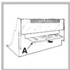
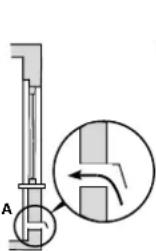
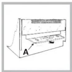
natural_image
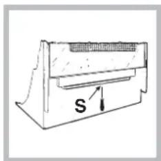
Technical line drawing of a mechanical device with labeled component A (no text or symbols beyond label)In gas cooker models, there is a sliding protection layer A that shields the lower compartment from the heat generated by the burner (see figure).
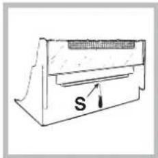
natural_image
Simple line drawing of a mechanical component with labeled 's' and directional arrow (no text or symbols beyond the label)To remove the sliding protection remove the screw S (see figure). To replace it, lock it in place with the screw S.
!Before using the oven make sure that the sliding protection is fixed correctly.
Oven light
The light may be switched on at any moment by pressing the OVEN LIGHT button.
* Only available in certain models.
Oven cooking advice table
| Food to be cooked | Wt. (Kg) | Cooking position of shelves from bottom | Temperature (°C) | Pre-heating time (min) | Cooking time (min.) |
| Pasta | |||||
| Lasagne | 2.5 | 4 | 200-210 | 10 | 75-85 |
| Cannelloni | 2.5 | 4 | 200 | 10 | 50-60 |
| Pasta bakes au gratin | 2.5 | 4 | 200 | 10 | 50-60 |
| Meat | |||||
| Veal | 1.5 | 3 | 200-210 | 10 | 95-100 |
| Chicken | 1.5 | 3 | 210-220 | 10 | 90-100 |
| Duck | 1.8 | 3 | 200 | 10 | 100-110 |
| Rabbit | 2.0 | 3 | 200 | 10 | 70-80 |
| Pork | 2.1 | 3 | 200 | 10 | 70-80 |
| Lamb | 1.8 | 3 | 200 | 10 | 100-105 |
| Fish | |||||
| Mackerel | 1.1 | 3 | 180-200 | 10 | 45-50 |
| Dentex | 1.5 | 3 | 180-200 | 10 | 45-55 |
| Trout baked in paper | 1.0 | 3 | 180-200 | 10 | 45-50 |
| Pizza | |||||
| Napolitan 1.0 4 210-220 15 | 20-25 | ||||
| Cake | |||||
| Biscuits | 0.5 | 4 | 180 | 15 | 25-35 |
| Tarts | 1.1 | 4 | 180 | 15 | 40-45 |
| Savoury pie | 1.0 | 4 | 180 | 15 | 50-55 |
| Raised Cakes | 1.0 | 4 | 170 | 15 | 40-45 |
| Grill cooking | |||||
| Veal steaks | 1 | 4 | 5 | 15-20 | |
| Cutlets | 1,5 | 4 | 5 | 20 | |
| Hamburgers | 1 | 3 | 5 | 20-30 | |
| Mackerels | 1 | 4 | 5 | 15-20 | |
| Toast sandwiches | n.° 4 | 4 | 5 | 4-5 | |
| Grill cooking with rotisserie | |||||
| Veal on the spit | 1 | - | 5 | 70-80 | |
| Chicken on the spit | 2 | - | 5 | 70-80 | |
| Grill cooking with multi-skewer rotisserie (only a few models) | |||||
| Meat kebabs | |||||
| Vegetable kebabs 1,0 | 0,8 | - | 5 | 40-45 | |
| 5 | 25-30 |
NB: cooking times are approximate and may vary according to personal taste. When cooking using the grill, the dripping-pan must always be placed on the 1st oven rack from the bottom.
! This appliance has been designed and manufactured in compliance with international safety standards.
The following warnings are provided for safety reasons and must be read carefully.
General safety
- These instructions are only valid for the countries whose symbols appear in the manual and on the serial number plate. The appliance was designed for domestic use inside the home and is not intended for commercial or industrial use.
- The appliance must not be installed outdoors, even in covered areas. It is extremely dangerous to leave the appliance exposed to rain and storms.
- Do not touch the appliance with bare feet or with wet or damp hands and feet.
- The appliance must be used by adults only for the preparation of food, in accordance with the instructions outlined in this booklet. Any other use of the appliance (e.g. for heating the room) constitutes improper use and is dangerous. The manufacturer may not be held liable for any damage resulting from improper, incorrect and unreasonable use of the appliance.
- The instruction booklet accompanies a class 1 (insulated) or class 2 - subclass 1 (recessed between 2 cupboards) appliance.
- Keep children away from the oven.
- Make sure that the power supply cables of other electrical appliances do not come into contact with the hot parts of the oven.
- The openings used for the ventilation and dispersion of heat must never be covered.
- Do not close the glass hob cover (selected models only) when the burners are alight or when they are still hot.
- Always use oven gloves when placing cookware in the oven or when removing it.
- Do not use flammable liquids (alcohol, petrol, etc...) near the appliance while it is in use.
- Do not place flammable material in the lower storage compartment or in the oven itself. If the appliance is switched on accidentally, it could catch fire.
- Always make sure the knobs are in the • position and that the gas tap is closed when the appliance is not in use.
- When unplugging the appliance, always pull the plug from the mains socket; do not pull on the cable.
- Never perform any cleaning or maintenance work without having disconnected the appliance from the electricity mains.
- If the appliance breaks down, under no circumstances should you attempt to repair the appliance yourself. Repairs carried out by inexperienced persons may cause injury or further malfunctioning of the appliance. Contact Assistance.
- Do not rest heavy objects on the open oven door.
- The appliance should not be operated by people (including children) with reduced physical, sensory or mental capacities, by inexperienced individuals or by anyone who is not familiar with the product. These individuals should, at the very least, be supervised by someone who assumes responsibility for their safety or receive preliminary instructions relating to the operation of the appliance.
- Do not let children play with the appliance.
Disposal
- When disposing of packaging material: observe local legislation so that the packaging may be reused.
- The European Directive 2002/96/EC relating to Waste Electrical and Electronic Equipment (WEEE) states that household appliances should not be disposed of using the normal solid urban waste cycle. Exhausted appliances should be collected separately in order to optimise the cost of re-using and recycling the materials inside the machine, while preventing potential damage to the atmosphere and to public health. The crossed-out dustbin is marked on all products to remind the owner of their obligations regarding separated waste collection.
Exhausted appliances may be collected by the public waste collection service, taken to suitable collection areas in the area or, if permitted by current national legislation, they may be returned to the dealers as part of an exchange deal for a new equivalent product.
All major manufacturers of household appliances participate in the creation and organisation of systems for the collection and disposal of old and disused appliances.
Respecting and conserving the environment
- You can help to reduce the peak load of the electricity supply network companies by using the oven in the hours between late afternoon and the early hours of the morning.
- Check the door seals regularly and wipe them clean to ensure they are free of debris so that they adhere properly to the door, thus avoiding heat dispersion.
Switching the appliance off
Disconnect your appliance from the electricity supply before carrying out any work on it.
Cleaning the appliance
! Do not use abrasive or corrosive detergents such as stain removers, anti-rust products, powder detergents or sponges with abrasive surfaces: these may scratch the surface beyond repair.
! Never use steam cleaners or pressure cleaners on the appliance.
- It is usually sufficient simply to wash the hob using a damp sponge and dry it with absorbent kitchen roll.
- The stainless steel or enamel-coated external parts and the rubber seals may be cleaned using a sponge that has been soaked in lukewarm water and neutral soap. Use specialised products for the removal of stubborn stains. After cleaning, rinse well and dry thoroughly. Do not use abrasive powders or corrosive substances.
- The hob grids, burner caps, flame spreader rings and the hob burners can be removed to make cleaning easier; wash them in hot water and non-abrasive detergent, making sure all burnt-on residue is removed before drying them thoroughly.
- For hobs with electronic ignition, the terminal part of the electronic lighting devices should be cleaned frequently and the gas outlet holes should be checked for blockages.
- The inside of the oven should ideally be cleaned after each use, while it is still lukewarm. Use hot water and detergent, then rinse well and dry with a soft cloth. Do not use abrasive products.
- Clean the glass part of the oven door using a sponge and a non-abrasive cleaning product, then dry thoroughly with a soft cloth. Do not use rough abrasive material or sharp metal scrapers as these could scratch the surface and cause the glass to crack.
- The accessories can be washed like everyday crockery, and are even dishwasher safe.
- Stainless steel can be marked by hard water that has been left on the surface for a long time, or by aggressive detergents containing phosphorus. After cleaning, rinse well and dry thoroughly. Any remaining drops of water should also be dried.
The cover
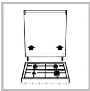
natural_image
Simple line drawing of a gas stove with four outlets and two upright doors (no text or symbols)If the cooker is fitted with a glass cover, this cover should be cleaned using lukewarm water. Do not use abrasive products. It is possible to remove the cover in order to make cleaning the area behind the hob easier. Open the cover fully and pull it
upwards (see figure).
! Do not close the cover when the burners are alight or when they are still hot.
Inspecting the oven seals
Check the door seals around the oven periodically. If the seals are damaged, please contact your nearest Authorised After-sales Service Centre. We recommend that the oven is not used until the seals have been replaced.
Gas tap maintenance
Over time, the taps may become jammed or difficult to turn. If this occurs, the tap must be replaced.
! This procedure must be performed by a qualified technician who has been authorised by the manufacturer.
natural_image
Pure technical diagram showing two circular components with directional arrows, no text or symbols presentReplacing the oven light bulb
- After disconnecting the oven from the electricity mains, remove the glass lid covering the lamp socket (see figure).
- Remove the light bulb and
replace it with a similar one: voltage 230 V, wattage 25 W, cap E 14.
- Replace the lid and reconnect the oven to the electricity supply.
Assistance
Please have the following information handy:
• The appliance model (Mod.).
• The serial number (S/N).
This information can be found on the data plate located on the appliance and/or on the packaging.
natural_image
Technical diagram of a cabinet with an inset showing a cross-section view of the door (no text or symbols present)natural_image
Diagram of a greenhouse with a stove, cooling tower, and piping (no text or labels)natural_image
Simple line drawing of a house interior with roof, stove, and electrical connections (no text or symbols)natural_image
Pure diagram of a mechanical component with no text, numbers, or symbols visibleВыравнивание
natural_image
Mechanical component diagram showing a cylindrical shaft with a downward rotation arrow (no text or symbols)natural_image
Technical line drawing of a mechanical device with labeled component A (no text or symbols beyond label)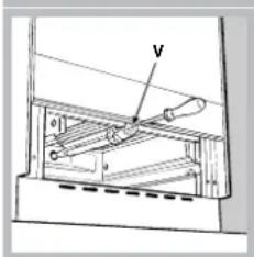
natural_image
Technical line drawing of a mechanical component with a handle and base (no text or symbols)natural_image
Mechanical component diagram showing a central hub with four arms and a central shaft, enclosed in a circular housing (no text or symbols)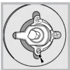
natural_image
Mechanical component diagram showing a central hub with four surrounding holes and a bolt, enclosed in a circular housing (no text or symbols)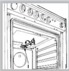
natural_image
Technical line drawing of a door with ventilation grilles and a small mechanical component inside (no text or symbols)рисунок);
natural_image
Diagram of a kitchen appliance with a door open, showing control buttons and a lid (no text or symbols)natural_image
Line drawing of a laptop oven with a handle and internal structure (no text or symbols)natural_image
Simple line drawing of a mechanical assembly with a lever and base (no text or symbols)natural_image
Technical line drawing of a mechanical component with labeled section A (no text or symbols beyond label)natural_image
Technical line drawing of a mechanical component with labeled dimension 'S' (no text or symbols beyond the label)natural_image
Simple line drawing of a kitchen appliance with a pan and four wheels, no text or symbols present.natural_image
Pure diagram of two circular components with directional arrows, no text or symbols presentnatural_image
Simple line drawing of a house interior with a stove, roof, and air vent (no text or symbols)natural_image
Simple line drawing of a house with a stove and roof, showing airflow or ventilation (no text or symbols)natural_image
Simple diagram showing a gray rectangle with a downward arrow and a black spiral shape, no text or symbols present.natural_image
Mechanical component diagram showing a cylindrical shaft with a curved arrow indicating rotation (no text or symbols)natural_image
Technical line drawing of a mechanical assembly with a tool inserted into a circular component (no text or symbols)natural_image
Technical line drawing of a mechanical component with labeled section A (no text or symbols beyond label)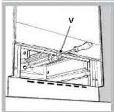
natural_image
Technical line drawing of a mechanical assembly with a tool interacting with a component (no text or symbols)natural_image
Mechanical component diagram showing a central hub with mounting holes and a pointer (no text or symbols)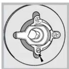
natural_image
Mechanical component diagram showing a central hub with four arms and a bolt, enclosed in a circular housing (no text or symbols)Налаштування гриля
natural_image
Technical line drawing of a door with ventilation grilles and a hanging component (no text or symbols)KN1G21/UA
KN1G21S/UA
natural_image
Mechanical assembly diagram showing a rotating component with labeled axes X and C (no text or symbols beyond labels)natural_image
Diagram of an open kitchen appliance with control panel and door, no visible text or symbolsРожен\*
natural_image
Diagram of an oven with a diagonal line indicating a cable or wire, showing internal structure without any text or symbols.natural_image
Simple line drawing of a mechanical or architectural component with a curved arrow indicating rotation (no text or symbols)natural_image
Technical line drawing of a mechanical component with labeled dimension 's' (no text or symbols beyond the label)natural_image
Simple line drawing of a kitchen appliance with a grater and two upward arrows (no text or symbols)natural_image
Pure mechanical diagram showing two circular components with a directional arrow, no text or symbols presentnatural_image
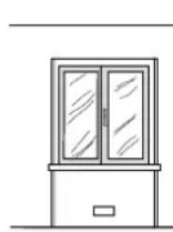
Simple line drawing of a room interior with glass doors, cabinet, and coffee cup (no text or symbols)natural_image
Diagram of a greenhouse with a central container and surrounding structures (no text or symbols)natural_image
Diagram of an electrical circuit setup with a box, transformer, and wiring (no text or labels)Išlyginimas
natural_image
Mechanical component diagram showing a cylindrical assembly with an arrow indicating force or direction (no text or symbols)Kojos* îlenda î lizdus, esančius po virykle.
Elektros jungtys
natural_image
Technical line drawing of a mechanical assembly with a tool inserted into a circular component (no text or symbols)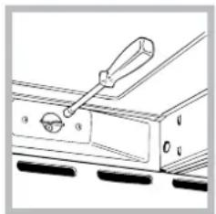
natural_image
Technical line drawing of a mechanical clamp or bracket with no visible text or symbolsnatural_image
Mechanical component diagram showing a central hub with four arms and a circular housing (no text or symbols)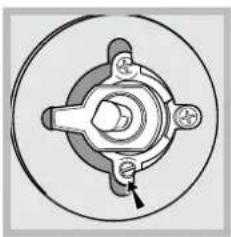
natural_image
Mechanical component diagram showing a central hub with four surrounding parts, no text or symbols present.natural_image
Illustration of a refrigerator with doors and control panel (no text or symbols)lešmas*
natural_image
Simple line drawing of a laptop with a screen and keyboard, no text or symbols presentnatural_image
Simple line drawing of a mechanical frame or bracket with no text or symbolsnatural_image
Simple line drawing of a mechanical component with no text or symbolsNorëdami nuimti apsaugr, atsukite varttir S (žr. pav.). Norëdami jí utdëti, pritvirtinkite varttu S.
natural_image
Simple line drawing of a rectangular frame with two small protrusions, mounted on a grid base (no text or symbols)natural_image
Pure technical diagram showing two circular components with an arrow indicating direction, no text or symbols present.Pagalba
Ventilâcijas atvere dedzinâdanai nepiecieđamâ gaisa plûsmai
Blakus esodā telpa
B
Telpa, kurai
nepiecieđama
ventilçdana
natural_image
Simple line drawing of a room with window, door, lamp, and coffee cup (no text or symbols)Atstatuma palielinâmjums starp durvîm un grîdas segumu
! Pçc tam, kad ierîce ir lietota ilgstođi, ieteicams atvçrt logu vai palielinât jebkâdu izmantoto ventilatoru darbîbas âtrumu.
Atbrîvođanâs no dûmiem
Tvaiki tiek izvadîti tiedi ârâ
natural_image
Simple line drawing of a house interior with a stove and air duct (no text or symbols)Tvaiki tiek izvadīti pa dūmvađu vai sazarotu dūmvađu sistçmu (rezervçta çdiena gatavođanas ierîcçm)
natural_image
Mechanical assembly diagram showing a cylindrical component with directional arrows indicating motion (no text or symbols)Ja ierîci ir nepiecieđams lîmeňot, katrâ plîts pamatnes stûrî tam îpađi paredzçtâs vietâs pieskr ŭvcjiet regulçjamas kâjas (skatît attçlu).
Kâjas* var ieskrůvçt attiecîgajâs ligzdâs zem plîts pamatnes.
Elektrîbas pieslçgdana
natural_image
Technical line drawing of a mechanical assembly with a tool inserted into a circular component (no text or symbols)- atskrūvçijiet sprauslu ar îpađu sprauslas uzmaucamo uzgrietňu atslęgu (skatît attçlu) vai 7 mm uzmaucamo uzgrietňu atslęgu un nomainiet ar jaunu sprauslu, kas ir piemçrota attiecîgajam gâzes veidam (skatîtDegd'u un sprauslu specifi kâciju tabula).
natural_image
Technical line drawing of a mechanical clamp or bracket with no visible text or symbolslestatiet gâzes plîts degd'a minimâlos iestatijumus:
- aizdedziniet degli (skatît "leslçgdana un lietodana");
-
pçc tam, kad grozâmais slçdzis ir bijis maksimâlajâ pozîcijâ (MAX) apmçram desmit minûtes, pagrieziet to uz minimâlo iestatîjumu (MIN);
-
nošemiet grozâmo slçdzi;
-
pievelciet vai atbrîvojiet termostata tapiñas ârpusç redzamâs regulçđanas skrûves (skatît attçlu), kamçr liesma ir neliela, bet stabila.
natural_image
Mechanical component diagram showing a central hub with four surrounding parts and an arrow indicating direction (no text or labels)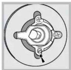
natural_image
Mechanical component diagram showing a central hub with four mounting holes and a central shaft (no text or labels)Grila pielâgođana
Grila degda sprauslas maiña:
- atskrüvcjiet skrüvi V (skatit attçlu) un noñemiet plîts degli;
natural_image
Technical line drawing of a door with circular components and a hanging mechanism (no text or symbols)- atskrūvçijet grila degd'a sprauslu ar îpađu sprauslas uzmaucamo uzgrietňu atslęgu (skatît attçlu) vai 7 mm uzmaucamo uzgrietňu atslęgu un nomainiet ar jaunu sprauslu, kas ir piemçrota attiecîgajam gâzes veidam (skatît Degd'u un sprauslu specifi kâciju tabula).
!
ar aizdedzes sveces vadiem un termoelementa caurulçm.
! Pšitupiegsaladzlegdkiend steådâjat nepiecieđama primârâ gaisa regulčdana.
! Pcc ierîces noregulçđanas, lai
to varçtu izmantot ar cita veida gâzi, iepriekđćjo vçrtçjuma maríçjumu nomainiet pret jauno, kas atbilst jaunajam gâzes veidam (đie maríçjumi ir pieejami pilnvarotos tehniskâs palîdzîbas centros).
! Ja izmantotâs gâzes spiediens ir citâds (vai mazliet atđíirîgs) nekâ ieteicamais spiediens, ieplüdes cauruđvadam ir jäpiestiprina piemçrots spiediena regulators, kas atbilst spçkâ esodajiem noteikumiem saistîbâ ar gâzes cauruđvadu noteikumiem.
Pirms pirmâs lietođanas reizes plîti ieteicams iztîrît. Rîkojieties saskaňâ ar instrukcijâm, kas aprakstítas "Tehniskâ apkope un tîrîđana" sadad'â.
Lai aizdegtu cepedkrâsns degli, pietuviniet liesmu vai gâzes dîiltavas F atverei (skatît attçlu), nospiediet CEPEDKRÂSNS vadîbas slçdzi un grieziet pretçji pulksteñrådîtâja virzienam, lîdz tas ir MAX pozîcijâ.
Ja pçc 15 sekundçm deglis vçl nav aizdegts, atlaidiet grozâmo slçdzi, atveriet cepeđkrâsns durvis un pagaidiet vismaz vienu minüti, bet pçc tam mçëiniet aizdegt degli vçlreiz.
! Cepedkråsns ir aprikota ar drođibas ieriči. Tâpçc CEPEDKRÅSNS vadibas slçdzis ir jânospiet vismaz uz seđâm sekundçm.
natural_image
Diagram of a kitchen appliance with labeled control panel (no text or symbols on the device itself)Grozâmais iesms\*
Lai lietotu iesmu (skatît attçlu), rîkojieties turpmâk minçtajâveidâ.
cepedkrâsns aizmugurçjâ paned'a atverç.
- Aktivizçijet funkciju, nospiețot GROZÂMÂ IESMA pogu.
natural_image
Simple line drawing of a mechanical or architectural component with no text or symbols! Nodalijuma (ja cepedkrâsns ar to ir aprîkota) iekđçjâs virsmas lietodanas laikâ var sakarst.
! Cepedkrâsns apakđçjâ nodalîjumâ nedrîkst novietot viegli uzliesmojođus materiâlus.
Gâzes cepeđkrâsnîm ir bîdâms aizsargslânis A, kas apakđcjo nodalîjumu aizsargâ pret degđa izstaroto siltumu (skatît attçlu).
Lai bîdâmo aizsargslâni noñemtu, atskrûvçjiet S skrûvi (skatît attçlu). Lai bîdâmo aizsargslâni uzstâdîtu atpakad', ievietojiet to pozîcijâ un ieskrûvçjiet S skrûvi.
natural_image
Simple line drawing of a mechanical component with labeled dimension 's' (no text or symbols beyond the label)! Pirms cepedkrâsns lietođanas pârbaudiet, vai bîdâmais aizsargslânis ir pareizi uzstâdîts
Çdiena gatavođanas ieteikumu tabula
LV
| Gatavojamais ēdiens | Svars (kg) | Plauktu poz icija no apakšas | Temperatura (°C) | Sild išanas laiks (minūtes) | Gatavošan as laiks (minūtes) |
| Pasta | |||||
| Lazanja | 2,5 | 4 | 200–210 | 10 | 75–85 |
| Cannelloni | 2,5 | 4 | 200 | 10 | 50–60 |
| Makaronu sacepumi | 2,5 | 4 | 200 | 10 | 50–60 |
| Ga ʃa | |||||
| Te ʃa ga ʃa | 1,5 | 3 | 200–210 | 10 | 95–100 |
| Vista | 1,5 | 3 | 210–220 | 10 | 90–100 |
| P ̄le | 1,8 | 3 | 200 | 10 | 100–110 |
| Trusis | 2,0 | 3 | 200 | 10 | 70–80 |
| Cūkga ʃa | 2,1 | 3 | 200 | 10 | 70–80 |
| Jērs | 1,8 | 3 | 200 | 10 | 100–105 |
| Zivis | |||||
| Makrele | 1,1 | 3 | 180–200 | 10 | 45–50 |
| Zobaine | 1,5 | 3 | 180–200 | 10 | 45–55 |
| Piparos cepta forele | 1,0 | 3 | 180–200 | 10 | 45–50 |
| Pica | |||||
| Napolita | 1,0 | 4 | 210–220 | 15 | 20–25 |
| Kūka | |||||
| Biskv ̄ti | 0,5 | 4 | 180 | 15 | 25–35 |
| P ̄r āgi | 1,1 | 4 | 180 | 15 | 40–45 |
| Pikantie p ̄r āgi | 1,0 | 4 | 180 | 15 | 50–55 |
| Uzbriestošas kūkas | 1,0 | 4 | 170 | 15 | 40–45 |
| Grila ēdieni | 4 | ||||
| Te ʃa ga ̄as steiki | 1 | 4 | 5 | 15–20 | |
| Ga ̄as siteni | 1,5 | 4 | 5 | 20 | |
| Hamburgeri | 1 | 3 | 5 | 20–30 | |
| Makreles | 1 | 4 | 5 | 15–20 | |
| Grauzdētas sviestmaizes | 4 maiz. | 4 | 5 | 4–5 | |
| Grila ēdieni, kas gatavoti uz iesma | |||||
| Te ʃa ga ̄a uz iesma | 1 | - | 5 | 70–80 | |
| Vistas ga ̄a uz iesma | 2 | - | 5 | 70–80 | |
| Grila ēdieni, kas gatavoti ar vairākiem iesmiem (tikai dažiem mode ̄iem) | 1,0 | - | 5 | 40–45 | |
| Ga ̄as kebabi Dārzenu kebabi | 0,8 | - | 5 | 25–30 |
natural_image
Technical line drawing of a mechanical assembly with two vertical components mounted on a grid base (no text or symbols)Ja plîts ir aprîkota ar stikla pârsegu, dis pârsegs ir jâtîra ar remdenu üdeni. Nelietojiet abrazîvus tîrîdanas lîdzekđus. Pârsegu var noñemt, lai vietu aiz plîts virsmas bûtu çrtâk tîrît. Atveriet pârsegu lîdz galam un pavelciet to uz augđu (skatît attçlu).
! Ja degdi ir iedegti vai joprojâm ir karsti, pârsegu nedrîkst aizvçrt.
Cepedkrâsns durtiňu blívju pârbaudîđana
Cepedkrâsns durtiňu blîves ir regulâri jâpârbauda. Ja blîves ir bojâtas, sazinieties ar tuvâko pilnvaroto pçcpârdođanas tehniskâs apkopes dienestu. Pirms blívju nomaiñas ieteicams cepedkrâsni nelietot.
Gâzes krâna tehniskâ apkope
Laika gaitâ krâniem var rasties aizsçrçjumi vai pagriedanas grütîbas. Tâdâ gadîjumâ krâns ir jâmaina.
! Dî procedûra jâveic kvalificçtam, rațotâja pilnvarotam tehniskajam darbiniekam.
Cepedkrâsns spuldzîdu maiňa
natural_image
Pure technical diagram showing two circular components with an arrow indicating direction (no text or symbols)- Kad cepedkrâsns ir atvienota no elektrotikla, noñemiet spuldzes niñas stikla vâciňu (skatît attçlu)..
-
Noñemiet spuldzîti un nomainiet to pret lîdzîgu: spriegums 230 V, jauda 25 W, lielums E 14.
-
Uzlieciet atpakad'vâciňu un atkal pieslçdziet cepedkrâsni elektrotiklam.
Palîdzîba
Lüdzu, norâdiet turpmâk minçto informâciju:
- ierîces modelis (Mod.);
- scrijas numurs (S/N).
Đî informâcija ir norâdîta uz tehnisko datu plâksnîtes, kas piestiprinâta ierîcei un/vai tâs iepakojumam.
natural_image
Diagram of a mechanical or electrical system with no visible text, numbers, or symbolsnatural_image
Simple line drawing of an electrical circuit setup with a box, wires, and power lines (no text or symbols)natural_image
Pure diagram of a mechanical component with no text, numbers, or symbolsnatural_image
Mechanical component diagram showing a cylindrical assembly with an arrow indicating rotation (no text or symbols)natural_image
Technical line drawing of a mechanical assembly with a tool inserted into a circular component (no text or symbols)natural_image
Line drawing of a mechanical switch or lever assembly with no visible text or symbolsnatural_image
Mechanical component diagram showing a central hub with four mounting holes and a circular housing (no text or symbols)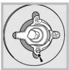
natural_image
Mechanical component diagram showing a central hub with four arms and a pointer indicating a specific part (no text or symbols present)Grilli seadmine
natural_image
Line drawing of a door with circular components and a small object inside (no text or symbols)natural_image
Illustration of an open refrigerator with a door and lid, no text or symbols presentnatural_image
Simple line drawing of a mechanical support structure (no text or symbols)natural_image
Technical line drawing of a mechanical component with labeled section A (no text or symbols beyond label)natural_image
Simple line drawing of a mechanical component with no text or symbolsnatural_image
Pure technical diagram of a mechanical or electrical component with no text, numbers, or symbolsnatural_image
Pure technical diagram showing two circular components with directional arrows, no text or symbols presentnatural_image
Diagram of a double door with a vertical structure and a magnified inset showing a hand mechanism (no text or symbols)natural_image
Simple line drawing of a room with a door, lamp, and coffee cup (no text or symbols)natural_image
Diagram of a house interior with a stove, roof, and heating elements (no text or labels)natural_image
Simple line drawing of a house interior with steam rising from the chimney, no text or symbols presentnatural_image
Abstract geometric pattern with a black arrow pointing upward and a gray grid background (no text or symbols)natural_image
Pure mechanical diagram showing a cylindrical component with an arrow indicating direction, no text or symbols present.natural_image
Technical line drawing of a mechanical assembly with a tool inserted into a circular component (no text or symbols)natural_image
Technical line drawing of a mechanical device with labeled component A (no text or symbols beyond label)natural_image
Technical line drawing of a mechanical component with a tool inserted, showing no text or symbolsnatural_image
Mechanical component diagram showing a central hub with mounting holes and a pointer (no text or labels)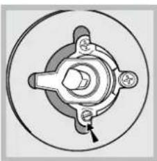
natural_image
Mechanical component diagram showing a central hub with four surrounding components and a small arrow pointing to a specific part (no text or symbols present)natural_image
Technical line drawing of a door frame with internal components and a downward arrow indicating direction (no text or symbols)natural_image
Line drawing of a window with circular elements and a small figure inside (no text or symbols)natural_image
Hand holding a small object inside a storage cabinet (no visible text or symbols)Төменгі белім
natural_image
Simple line drawing of a mechanical or architectural component with no text or symbolsnatural_image
Line drawing of a microwave oven with a hand pointing to the interior (no text or symbols)natural_image
Technical line drawing of a mechanical component with labeled section A (no text or symbols beyond label)natural_image
Simple line drawing of a mechanical component with labeled 'S' and directional arrow (no text or symbols beyond the label)natural_image
Simple line drawing of a gas stove with four wheels and an open lid (no text or symbols)natural_image
Pure technical line drawing of a mechanical component with no text or symbols
- Operating Instructions COOKER AND OVEN
- Contents
- RS
- Description of the appliance
- Overall view
- Описание изделия
- Общий вид
- Description of the appliance Control panel
- Room ventilation
- Disposing of combustion fumes
- Positioning and levelling
- Levelling
- Electrical connection
- Gas connection
- Gas connection using a flexible rubber hose
- GB
- Connecting a flexible jointless stainless steel pipe to a threaded attachment
- Checking the connection for leaks
- Adapting to different types of gas
- Adapting the hob
- Adapting the oven
- Adjusting the gas oven burner's minimum setting:
- Adapting the grill
- Using the hob
- Lighting the burners
- Practical advice on using the burners
- Using the oven
- Lighting the oven
- Adjusting the temperature
- Grill
- Turnspit\*
- Timer\*
- Lower compartment\*
- Oven light
- Oven cooking advice table
- General safety
- Disposal
- Respecting and conserving the environment
- Switching the appliance off
- Cleaning the appliance
- Inspecting the oven seals
- Gas tap maintenance
- ! This procedure must be performed by a qualified technician who has been authorised by the manufacturer.
- Replacing the oven light bulb
- Assistance
- Please have the following information handy:
- Выравнивание
- Налаштування гриля
- Рожен\*
- Išlyginimas
- Elektros jungtys
- Pagalba
- Atbrîvođanâs no dûmiem
- Elektrîbas pieslçgdana
- lestatiet gâzes plîts degd'a minimâlos iestatijumus:
- Grila pielâgođana
- Grozâmais iesms\*
- Çdiena gatavođanas ieteikumu tabula
- Cepedkrâsns durtiňu blívju pârbaudîđana
- Gâzes krâna tehniskâ apkope
- Cepedkrâsns spuldzîdu maiňa
- Palîdzîba
- Grilli seadmine
- Төменгі белім
Brand : INDESIT
Model : KN1G21S(W)/UA
Category : Cooker