HT-SL70 - Soundbar SHARP - Free user manual and instructions
Find the device manual for free HT-SL70 SHARP in PDF.
| Product type | Home theater soundbar with subwoofer |
| Brand | SHARP |
| Model | HT-SL70 |
| Soundbar dimensions (horizontal configuration for TV 46") | 1071 x 26 x 50 mm (W x H x D) |
| Soundbar dimensions (horizontal configuration for TV 52") | 1204 x 26 x 50 mm (W x H x D) |
| Subwoofer dimensions | 115 x 422 x 307 mm (W x H x D) |
| Soundbar weight (horizontal configuration for TV 46") | 1.15 kg |
| Soundbar weight (horizontal configuration for TV 52") | 1.20 kg |
| Subwoofer weight | 4.50 kg |
| Power supply | AC 120 V ~ 60 Hz |
| Power consumption | 40 W |
| Total RMS output power | 200 W |
| Front left/right power (RMS) | 50 W per channel at 3 ohms, 1 kHz, 10% THD |
| Subwoofer power (RMS) | 100 W at 4 ohms, 100 Hz, 10% THD |
| Soundbar speaker type | 2.2 x 11.5 cm, full-range |
| Soundbar speaker impedance | 3 ohms per channel (4 in parallel) |
| Subwoofer speaker type | 16 cm (6-5/16") woofer |
| Subwoofer impedance | 4 ohms |
| HDMI connectivity | 1 input, 1 output with ARC (Audio Return Channel) |
| Analog audio input | 3.5 mm stereo mini-jack plug |
| Supported audio formats (HDMI) | PCM only |
| Installation methods | Horizontal stand, vertical stand, wall mounting |
| Included accessories | HDMI and audio cables, soundbar and subwoofer brackets, drilling template, pads |
| Maintenance | Clean with a soft dry cloth. Do not use chemical products. |
| Important safety instructions | Do not expose to moisture, unplug during storms, use on a stable surface. |
Frequently Asked Questions - HT-SL70 SHARP
User questions about HT-SL70 SHARP
0 question about this device. Answer the ones you know or ask your own.
Ask a new question about this device
Download the instructions for your Soundbar in PDF format for free! Find your manual HT-SL70 - SHARP and take your electronic device back in hand. On this page are published all the documents necessary for the use of your device. HT-SL70 by SHARP.
USER MANUAL HT-SL70 SHARP
Thank you for purchasing this SHARP product. To obtain the best performance from this product, please read this manual carefully. It will guide you in operating your SHARP product.
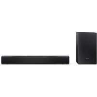
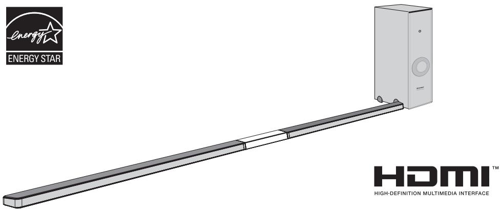
HT-SL70 and HT-SL75 Sound Bar Home Theater system consisting of Sound Bar and Subwoofer.
Notes:
- This product is recommended for flat panel TV (LCD and plasma).
- For HDMI connection, this product only supports PCM (Pulse Code Modulation) signals.
- This product is controlled via HDMI CEC (Consumer Electronics Control) specification, therefore for HDMI connection, your TV's CEC must be enabled. For detail, refer to the operation manual of the TV.
- For TV without HDMI CEC, headphone or RCA (variable output) analogue connection is available.
- For TV without HDMI, headphone or RCA (variable output) connection is required.
- This unit supports HDMI which enables Audio Return Channel (ARC).
Recommended Connection:
| TV Type | CEC FUNCTION | CONNECTION | CONNECTION METHOD |
| HDMI( with ARC) | MUST BE ENABLED | HDMI IN(ARC) | Page 11,Method 1 |
| with HDMI | MUST BE ENABLED | HDMI IN | Page 11,Method 2 |
| HDMI TV without CEC & ARC or non HDMI TV | NONE | HEADPHONE OUT | Page 12,Method 1 |
| RCA(VARIABLE OUT) | Page 12,Method 2 |
Accessories
The following accessories are included. This product has no remote control.
| RCA to Headphone Cable (1pin - 2 pins) x 1 (QCNWGA064AWPZ) | Subwoofer Stand x 2 (GITAUA004AW01) | Audio Cable x 1 (QCNWGA062AWPZ) | HDMI Cable x 1 (QCNWGA065AWPZ) | Wall Mount Bracket x 2 (LHLDZA267AWSA) | ||||
| Wall Mount Angle x 2 (LANGKA225AW01) | Pattern Paper For HT-SL75 only: (TCAUHA028AWZZ) For HT-SL70 only: (TCAUHA027AWZZ) | Speaker Wire For HT-SL75 only: (QCNWHA046AW01) For HT-SL70 only: (QCNWHA043AW01) | Sound Bar Stand x 2 (GITAUA012AW01) | Screw for Brackets x 6 (XEBY830P08000) | Sound Bar Stand Cushion x 2 (PCUSSA190AWZZ) | |||
For HT-SL75 only.
| Sound Bar Cover Joint for 60" TV (short) x 1 (GCOVAA331AW01) | Sound Bar Cover Joint for 70" TV (long) x 1 (GCOVAA333AW01) | Stand Cover x 2 (GCOVAA330AW01) | Stand Base x 2 (GDAI-A016AW01) |
For HT-SL70 only.
| Sound Bar Cover Joint for 46" TV (short) x 1 (GCOVAA300AW01) | Sound Bar Cover Joint for 52" TV (long) x 1 (GCOVAA302AW01) | Stand Cover x 2 (GCOVAA306AW01) | Stand Base x 2 (GDAI-A013AW01) |
The illustrations printed in this operation manual are for the model HT-SL70.

CAUTION
RISK OF ELECTRIC SHOCK DO NOT OPEN

CAUTION: TO REDUCE THE RISK OF ELECTRIC SHOCK,DO NOT REMOVE COVER (OR BACK). NO USER-SERVICEABLE PARTS INSIDE.REFER SERVICING TO QUALIFIED SERVICE PERSONNEL.
Explanation of Graphical Symbols:

The lightning flash with arrowhead symbol, within an equilateral triangle, is intended to alert the user to the presence of uninsulated "dangerous voltage" within the product's enclosure that may be of sufficient magnitude to constitute a risk of electric shock to persons.

The exclamation point within an equilateral triangle is intended to alert the user to the presence of important operating and maintenance (servicing) instructions in the literature accompanying the appliance.
WARNING: TO REDUCE THE RISK OF FIRE OR ELECTRIC SHOCK, DO NOT EXPOSE THIS APPLIANCE TO RAIN OR MOISTURE.
FOR YOUR RECORDS
For your assistance in reporting this unit in case of loss or theft, please record below the model number and serial number which are located on the rear of the unit. Please retain this information.
Model number
Serial number
Date of purchase
Place of purchase
··
NOTE
This equipment has been tested and found to comply with the limits for a Class B digital device, pursuant to Part 15 of the FCC Rules. These limits are designed to provide reasonable protection against harmful interference in a residential installation. This equipment generates, uses, and can radiate radio frequency energy and, if not installed and used in accordance with the instructions, may cause harmful interference to radio communications. However, there is no guarantee that interference will not occur in a particular installation. If this equipment does cause harmful interference to radio or television reception, which can be determined by turning the equipment off and on, the user is encouraged to try to correct the interference by one or more of the following measures:
- Reorient or relocate the receiving antenna.
- Increase the separation between the equipment and receiver.
- Connect the equipment into an outlet on a circuit different from that to which the receiver is connected.
- Consult the dealer or an experienced radio/TV technician for help.
WARNING
FCC Regulations state that any unauthorized changes or modifications to this equipment not expressly approved by the manufacturer could void the user's authority to operate this equipment.
ENERGY STAR® Program Information

Products that have earned the ENERGY STAR are designed to protect the environment through superior energy efficiency.
ENERGY STAR® is a U.S. registered mark.
HDMI, the HDMI Logo, and High-Definition Multimedia Interface are trademarks or registered trademarks of HDMI Licensing LLC in the United States and other countries.
Electricity is used to perform many useful functions, but it can also cause personal injuries and property damage if improperly handled. This product has been engineered and manufactured with the highest priority on safety. However, improper use can result in electric shock and/or fire. In order to prevent potential danger, please observe the following instructions when installing, operating and cleaning the product. To ensure your safety and prolong the service life of this product, please read the following precautions carefully before use.
1) Read these instructions.
2) Keep these instructions.
3) Heed all warnings.
4) Follow all instructions.
5) Do not use this apparatus near water.
6) Clean only with dry cloth.
7) Do not block any ventilation openings. Install in accordance with the manufacturer's instructions.
8) Do not install near any heat sources such as radiators, heat registers, stoves, or other apparatus (including amplifiers) that produce heat.
9) Do not defeat the safety purpose of the polarized or grounding-type plug. A polarized plug has two blades with one wider than the other. A grounding type plug has two blades and a third grounding prong. The wide blade or the third prong are provided for your safety. If the provided plug does not fit into your outlet, consult an electrician for replacement of the obsolete outlet.
10) Protect the power cord from being walked on or pinched particularly at plugs, convenience receptacles, and the point where they exit from the apparatus.
11) Only use attachments/accessories specified by the manufacturer.
12) Use only with the cart, stand, tripod, bracket, or table specified by the manufacturer, or sold with the apparatus. When a cart is used, use caution when moving the cart/apparatus combination to avoid injury from tip-over.
13) Unplug this apparatus during lightning storms or when unused for long periods of time.
14) Refer all servicing to qualified service personnel. Servicing is required when the apparatus has been damaged in any way, such as power-supply cord or plug is damaged, liquid has been spilled or objects have fallen into the apparatus, the apparatus has been exposed to rain or moisture, does not operate normally, or has been dropped.
Additional Safety Information
15) Power Sources - This product should be operated only from the type of power source indicated on the marking label. If you are not sure of the type of power supply to your home, consult your product dealer or local power company. For product intended to operate from battery power, or other sources, refer to the operating instructions.
16) Overloading - Do not overload wall outlets, extension cords, or integral convenience receptacles as this can result in a risk of fire or electric shock.
17) Object and Liquid Entry - Never push objects of any kind into this product through openings as they may touch dangerous voltage points or short-out parts that could result in a fire or electric shock. Never spill liquid of any kind on the product.
18) Damage Requiring Service - Unplug this product from the wall outlet and refer servicing to qualified service personnel under the following conditions:
a) When the AC cord or plug is damaged,
b) If liquid has been spilled, or objects have fallen into the product,
c) If the product has been exposed to rain or water,
d) If the product does not operate normally by following the operating instructions. Adjust only those controls that are covered by the operating instructions as an improper adjustment of other controls may result in damage and will often require extensive work by a qualified technician to restore the product to its normal operation,
e) If the product has been dropped or damaged in any way, and
f) When the product exhibits a distinct change in performance - this indicates a need for service.
19) Replacement Parts - When replacement parts are required, be sure the service technician has used replacement parts specified by the manufacturer or have the same characteristics as the original part. Unauthorized substitutions may result in fire, electric shock, or other hazards.
20) Safety Check - Upon completion of any service or repairs to this product, ask the service technician to perform safety checks to determine that the product is in proper operating condition.
21) Wall or ceiling mounting - When mounting the product on a wall or ceiling, be sure to install the product according to the method recommended by the manufacturer.
22) Power Lines - An outside antenna system should not be located in the vicinity of overhead power lines or other electric light or power circuits, or where it can fall into such power lines or circuits. When installing an outside antenna system, extreme care should be taken to keep from touching such power lines or circuits as contact with them might be fatal.
23) Protective Attachment Plug - The product is equipped with an attachment plug having overload protection. This is a safety feature. See Instruction Manual for replacement or resetting of protective device. If replacement of the plug is required, be sure the service technician has used a replacement plug specified by the manufacturer that has the same overload protection as the original plug.
24) Stand - Do not place the product on an unstable cart, stand, tripod or table. Placing the product on an unstable base can cause the product to fall, resulting in serious personal injuries as well as damage to the product. Use only a cart, stand, tripod, bracket or table recommended by the manufacturer or sold with the product. When mounting the product on a wall, be sure to follow the manufacturer's instructions. Use only the mounting hardware recommended by the manufacturer.
CONSUMER LIMITED WARRANTY
SHARP ELECTRONICS CORPORATION warrants to the first consumer purchaser that this Sharp brand product (the "Product"), when ship in its original container, will be free from defective workmanship and materials, and agrees that it will, at its option, either repair the defect or replace the defective Product or part thereof with a new or remanufactured equivalent at no charge to the purchaser for parts or labor for the period(s) set forth below.
This warranty does not apply to any appearance items of the Product nor to the additional excluded item(s) set forth below nor to any Product the exterior of which has been damaged or defaced, which has been subjected to improper voltage or other misuse, abnormal service or handling, or which has been altered or modified in design or construction.
In order to enforce the rights under this limited warranty, the purchaser should follow the steps set forth below and provide proof of purchase to the servicer.
The limited warranty described herein is in addition to whatever implied warranties may be granted to purchasers by law. ALL IMPLIED WARRANTYES INCLUDING THE WARRANTYES OF MERCHANTABILITY AND FITNESS FOR USE ARE LIMITED TO THE PERIOD(S) FROM THE DATE OF PURCHASE SET FORTH BELOW. Some states do not allow limitations on how long an implied warranty lasts, so the above limitation may not apply to you.
Neither the sales personnel of the seller nor any other person is authorized to make any warranties other than those described herein, or to extend the duration of any warranties beyond the time period described herein on behalf of Sharp.
The warranties described herein shall be the sole and exclusive warranties granted by Sharp and shall be the sole and exclusive remedy available to the purchaser. Correction of defects, in the manner and for the period of time described herein, shall constitute complete fulfillment of all liabilities and responsibilities of Sharp to the purchaser with respect to the Product, and shall constitute full satisfaction of all claims, whether based on contract, negligence, strict liability or otherwise. In no event shall Sharp be liable, or in any way responsible, for any damages or defects in the Product which were caused by repairs or attempted repairs performed by anyone other than an authorized servicer. Nor shall Sharp be liable or in any way responsible for any incidental or consequential economic or property damage. Some states do not allow the exclusion of incidental or consequential damages, so the above exclusion may not apply to you.
THIS WARRANTY GIVES YOU SPECIFIC LEGAL RIGHTS. YOU MAY ALSO HAVE OTHER RIGHTS WHICH VARY FROM STATE TO STATE.
Model Specific Section
Your Product Model Number & Description:
Warranty Period for this Product:
Additional Item(s) Excluded from Warranty Coverage (if any):
Where to Obtain Service:
What to do to Obtain Service:
HT-SL70 / HT-SL75 Sound Bar Home Theater System
(Be sure to have this information available when you need service for your Product.)
One (1) year parts and labor from the date of purchase.
Non-functional accessories, supplies, and consumable items.
At a Sharp Authorized Servicer located in the United States. To find a location of the nearest Sharp Authorized Servicer, call Sharp toll free at 1-800-BE-SHARP.
Ship prepaid or carry in your Product to a Sharp Authorized Servicer. Be sure to have Proof of Purchase available. If you ship the Product, be sure it is insured and packaged securely.
TO OBTAIN SUPPLY, ACCESSORY OR PRODUCT INFORMATION, CALL 1-800-BE-SHARP
SHARP ELECTRONICS CORPORATION
Sharp Plaza, Mahwah, New Jersey 07495-1163
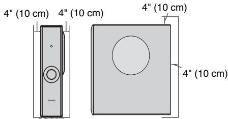
General
- Please ensure that the equipment is positioned in a well-ventilated area and ensure that there is at least 4^ (10 cm) of free space along the sides, top and back of the equipment.
- Use the unit on a firm, level surface free from vibration.
- Keep the unit away from direct sunlight, strong magnetic fields, excessive dust, humidity and electronic/electrical equipment (home computers, fax machines, etc.) which generate electrical noise.
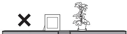
- Do not place anything on top of the system.
- Do not expose the unit to moisture, to temperatures higher than 140^ (60^) or to extremely low temperatures.
- If your system does not work properly, disconnect the AC power cord from the AC outlet and replug.
- In case of an electrical storm, unplug the unit for safety.
- Hold the AC power plug by the head when removing it from the AC outlet, as pulling the cord can damage internal wires.
The AC power plug is used as a disconnect device and shall always remain readily operable. - Do not remove the outer cover, as this may result in electric shock. Refer internal service to your local SHARP service facility.
This unit should only be used within the range of 41^ - 95^ (5^ - 35^)
Warnings:
- The voltage used must be the same as that specified on this unit. Using this product with a higher voltage other than that which is specified is dangerous and may result in a fire or other type of accident causing damage. SHARP will not be held responsible for any damage resulting from use of this unit with a voltage other than that which is specified.
- To prevent fire or shock hazard, do not expose this appliance to dripping or splashing. No object filled with liquids, such as vases shall be placed on the apparatus.
Sound bar

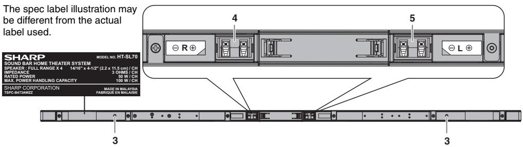
REAR VIEW
Reference page
-
Right Front Speaker Terminal (Red/Black) 10
5.Left Front Speaker Terminal (White/Black)....10
at Speaker Terminal (White/Black) . . . 10 -
Left Front Speaker
- Right Front Speaker
- Bass Reflex Duct
Subwoofer
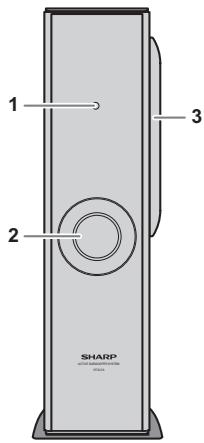
FRONT VIEW
Reference page
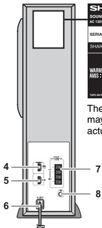
REAR VIEW
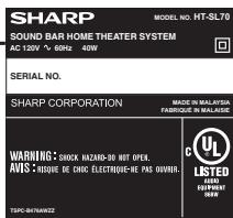
The spec label illustration may be different from the actual label used.
Reference page
- Stand-by Indicator
- Bass Reflect Duct
3.Woofer
4.HDMI (TV ARC) Output Terminal. 11
5.HDMI Input Terminal 11
6.AC Power Cord 10
7.Speaker Terminal. 10
8. Audio In (TV) Terminal 12
Make sure to unplug the AC power cord before installing the unit or changing the position.
Select from three installation methods according to the preferred position.
- Using stand (horizontal arrangement)
For 52", 60" or 70" TV sound bar assembly.
| For model HT-SL75 | Use Sound bar cover joint (short:369 mm) for 60" TV. |
| Use Sound bar cover joint (long:594 mm) for 70" TV. |
| For model HT-SL70 | Use Sound bar cover joint (long:188 mm) for 52" TV. |
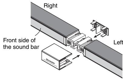
- Pull out both joint covers as below.
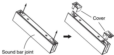
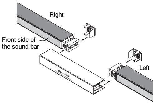
- Place the two sound bars near to each other and slot in the sound bar joint and its covers as below.
For 46" TV sound bar assembly
| For model HT-SL70 | Use Sound bar cover joint (short:55 mm) for 46" TV. |
- Pull out the joint cover as below.
Sound bar joint (short)
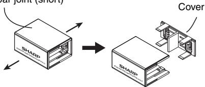
- Place the two sound bars adjacent to each other and slot in the sound bar joint and its cover as below.
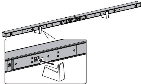
To fix the sound bar stand
- Peel off the double sided tape separator and attach the sound bar stand cushion at the bottom surface of the sound bar stand.
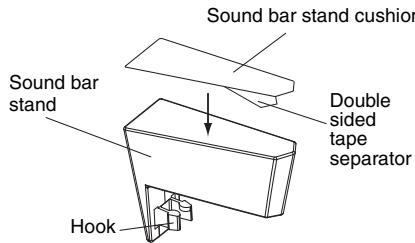
- Fix the sound bar stand as shown.
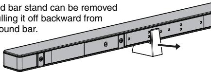
Note:
Sound bar stand can be removed
by pulling it off backward from
the sound bar.
Suggestion of the sound bars and LCD TV horizontal arrangement.
2. Using stand (vertical arrangement)
For model
HT-SL75
Use sound bar stand cover: 10 - 2 / 16^n (257 mm).
Use stand base: 13 - 7 / 32^n (336 mm).
For model
HT-SL70
Use sound bar stand cover: 6 - 3/32" (155 mm).
Use stand base: 6 - 15/16" (176 mm).
- Pull out the cover of sound bar stand as below.
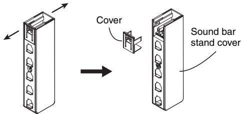
- Slot in the sound bar into the sound bar stand and fix its cover as shown.
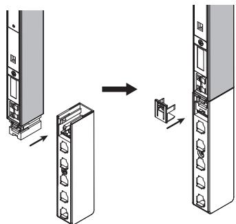
- Slot in the sound bar to the base stand according to your TV size.
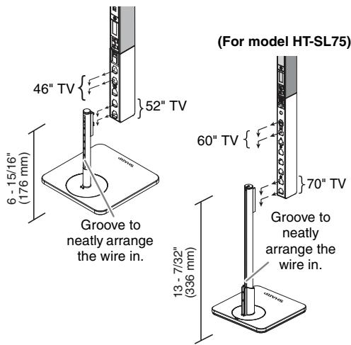
(For model HT-SL70)
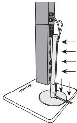
Slot in the wire inside the
groove or slit for better
wire arrangement.
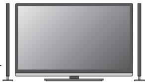
Suggestion of the
sound bars and
LCD TV arrangement.
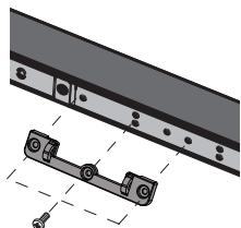
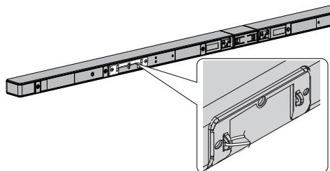
3. To mount the sound bar on the wall
- Fix the brackets to the holes as shown.
(Model HT-SL75: for 60" and 70" TV)
(Model HT-SL70: for 52" TV)
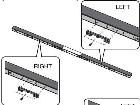
(Model HT-SL70: for 46" TV)
RIGHT
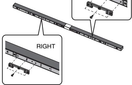
Caution:
Be careful not to
fix the bracket
upside down.

Caution:
- Be very careful to prevent the sound bar from falling when mounting on the wall.
- Before mounting, check the wall strength. (Do not put on the veneer plaster or whitewashed wall. The sound bar may fall.) If unsure, consult a qualified service technician.
- Mounting screws are not supplied. Use appropriate ones.
- Check all wall mount angle screws for looseness.
- Select a good location. If not, accidents may occur on the sound bar may get damaged.
- SHARP is not responsible for accidents resulting from improper installation.
- Do not let children dangle on the sound bar once it is attached on the wall as it can cause damage and injury.
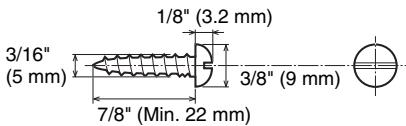
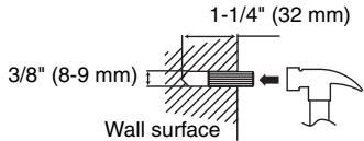
Driving screws
SHARP designed the sound bar so you may hang them on the wall. Use proper screws (not supplied). See below for size and type.
Fixing wall mount angle
Fix the pattern paper to the wall in horizontal position as below.
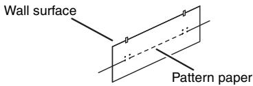
2 Make a hole on the wall following the screw point marks on the pattern paper by using a drill.
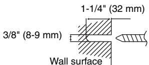
3 Fix a wall mount plug (not supplied) into the hole using a hammer, until it is flush with the wall surface.
4 Screw the wall mount angle to the wall as shown in the illustration. (Total screw is 4 pieces)
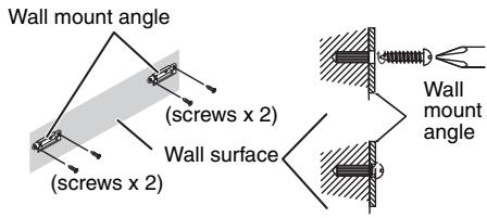
Note:
Make sure all screws are fully tightened. (screws are not supplied)
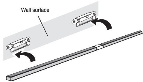
Installing the sound bar
1 Align the wall mount slot at the sound bar to the wall mount angle.
2 Slot the sound bar into the wall mount angle.
3 Fix them securely.
Falling prevention
Safety wires (not supplied) are useful to prevent the sound bar from falling off the table.
Loop the safety wires (not supplied) into each hole as shown and tie the safety wires to the LCD TV stand.
Placing the system
Installation image:
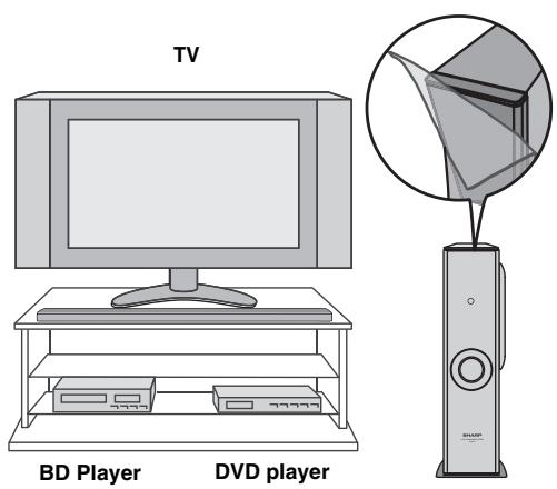
Place the system as shown.
Remove the protective film covering the sound bar and subwoofer before using the system.
Notes:
- As the sound from the system is omni-directional, you can place the speaker anywhere you like. However, it is recommended to place it as close to the TV as possible.
The front panel of the speaker is not removable.
Caution:
Do not change the installation direction when the unit is turned on.
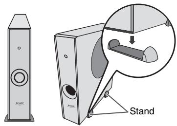
Placing the stand
Place the stand as shown.
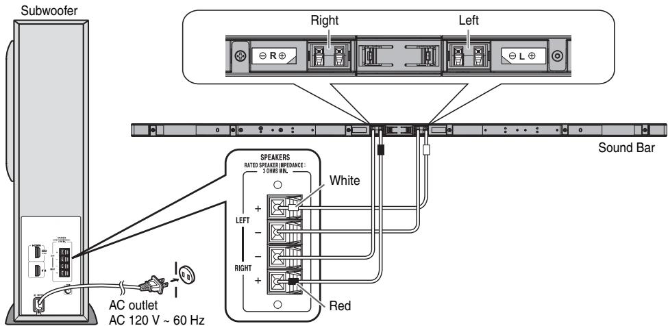
System connections
Make sure to unplug the AC power cord before making any connections.
CAUTION:
TO PREVENT ELECTRIC SHOCK, MATCH WIDE BLADE OF PLUG TO WIDE SLOT, FULLY INSERT.
Speaker connection
Connect the wire without insulation tube to the minus (-) terminal, and the wire with red and white insulation tube to the plus (+) terminal.
Caution:
-
Use speaker with an impedance of 3 ohms or more, as lower impedance speaker can damage the unit.
-
Do not make a mistake when connecting the right and left speakers. The right speaker is the one on the right side when you face the unit.
- Do not let the bare speaker wires touch each other.
- Do not allow any objects to fall into or to be placed in the bass reflex duct.
- Do not stand or sit on the subwoofer/sound bar. You may be injured.
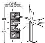
INCORRECT
Connecting to TV (with HDMI)
Caution:
- Turn off all other equipment before making this connection.
- Set the TV at low volume before turning on the system.
Notes:
- This unit supports HDMI which enables ARC (Audio Return Channel).
- To enable ARC make sure to use High Speed HDMI™ cable (with ARC).
This ARC feature requires TV that supports ARC. Refer the operation manual of the TV to determine which terminal supports ARC.
To listen to the sound from a non-ARC-compatible TV, connect the audio output from TV to this system's AUDIO IN (TV) terminal. (refer page 12)
This unit can be operated (power on/off or volume up/down) via a TV or similar component which supports HDMI CEC (Consumer Electronics Control). If this does not work, it does not mean this system is faulty. Refer to the operation manual of the respective component on how to activate the CEC.
Example: Go to the Menu of the component to search and enable the CEC. Different brands may have different naming for the CEC. For Sharp LCD TV, it is named as AQUOS LINK.
- To listen to the sound from this system, you will need to adjust settings within the TV menu.
For details, refer to the operation manual of the TV. - If you are unable to select external speaker setting from the TV menu (E.g. For Sharp LCD TV, it is named as AQUOS AUDIO SP), turn the CEC OFF and ON again.
- Make sure the LCD TV Audio output setting is set to PCM, not other formats such as Dolby Digital, DTS, etc.
To enjoy 3D images, this system must be connected to a 3D-compatible TV and components (3D BD player, etc.) via High Speed HDMI cables. Put on the 3D glasses, otherwise 3D images may not be viewed properly.
Select from the 2 methods below:
1. Method 1
This connection is for HDMI TV with ARC (Audio Return Channel).
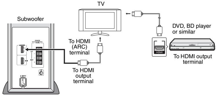
Notes:
Refer to the operation manual of the equipment to be connected.
- Fully insert the plugs to avoid fuzzy pictures or noises.
2. Method 2
This connection is for HDMI TV without ARC (Audio Return Channel).
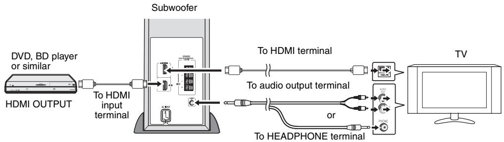
Notes:
- To listen to sound via TV, turn off your connected DVD player or BD player or similar component.
- Connecting via this method may disable TV internal speakers.
Connecting a TV (with AUDIO IN (TV))
Connect to the TV using an audio cable.
- Method 1
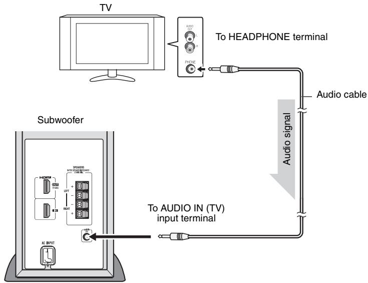
Notes:
- Connecting via this method may disable TV internal speakers.
-
In some cases, a small background noise could emit from the sound bar, when you use the headphone connection with a TV-Set. In such case, please change the connection to the HDMI/ARC or RCA-connection! This effect depends on the used TV-Brand, model and age, and it is not a quality matter from the sound bar!
-
Method 2
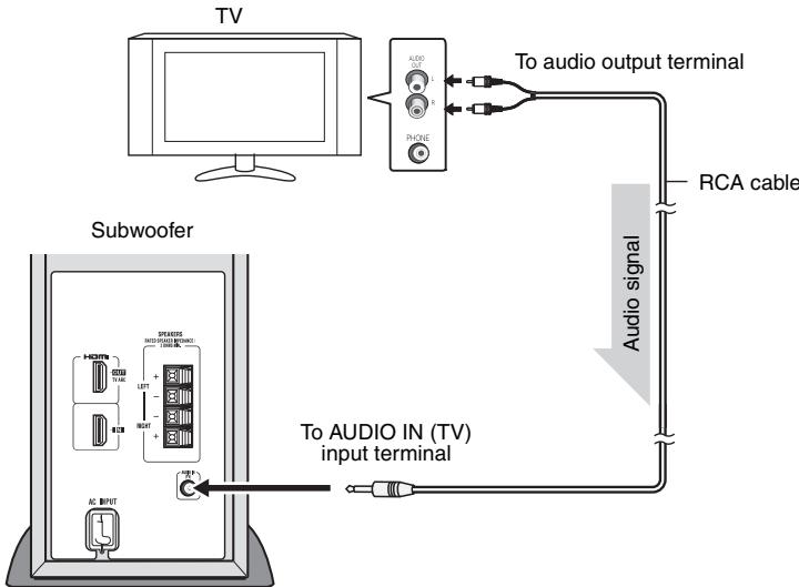
Note:
To control the volume, some setting in the TV MENU is needed. For details refer to the operation manual of the TV. Example: Go to the Setting Menu of the TV, select AUDIO OUT and choose VARIABLE.
However if this does not work, please use method 1.
Make sure to enable the HDMI CEC when making HDMI connection. For details, refer to the operation manual of the TV.
To turn the power on
Plug the AC power cord into a AC outlet, the stand-by indicator turns RED.
This unit will automatically power on if:
- TV or similar component which supports HDMI CEC, is turned on.
- Audio signal is detected from Audio input.
The stand-by indicator will turn BLUE if TV signal is detected.
Notes:
- HDMI input will override the Audio input signal.
- Audio input will function only when there is no signal from HDMI input.
- A slight audio delay after TV is turned ON does not mean that the system is faulty. This is normal.
- "AQUOS speaker is enabled" message will be displayed if SHARP LCD TV does not detect HT-SL70 / HT-SL75 during power on. However the message "AQUOS audio with AQUOS LINK is enabled" will be displayed soon as HT-SL70 / HT-SL75 is detected. These messages may vary for other TV model.
Audio Return Channel (ARC) (Audio Return Channel submenu)
The Audio Return Channel (ARC) enables an HDMI ARC-capable TV to send the audio stream to the HDMI OUT terminal of the receiver. To use this function, your TV must support the ARC. Make sure the LCD TV Audio output setting is set to PCM, not other formats such as Dolby Digital, DTS, etc. For details, refer to the operation manual of the TV.
Volume
Volume can only be controlled from your TV.
Power Off
This unit will automatically go to stand-by mode (indicator turns RED) if:
- TV or similar component which supports HDMI CEC, is turned off.
- No signal from Audio input is detected after 20 minutes.
Many potential problems can be resolved by the owner without calling a service technician.
If something is wrong with this product, check the following before calling your authorized SHARP dealer or service center.
General
| Symptom | Possible cause |
| ● No sound is heard. | ● Is the input signal (selection) set properly?● Is HDMI compliant equipment being used?● Is the HDMI cable connected correctly?● Is the HDMI cable of the correct type being used? (with ARC)● Does the sound input support PCM signal?● Do not connect or disconnect an HDMI cable while power is on. This may lead to operation problems. |
| ● Noise is heard during playback. | ● Move the speaker away from any computers or mobile phones. |
| ● The power is not turned on. | ● Is the unit unplugged?● The protection circuit may be activated. Unplug and plug in the power cord again after 5 minutes or more. |
| ● Volume cannot be controlled. | ● Check if the HDMI CEC is enabled.● For headphone or RCA, TV setting (VARIABLE) is required. |
| ● 3D images not displayed on the TV. | ● Depending on the TV and Video component, 3D images may not be displayed. Check the operation manual of the respective component. |
| ● Background noise appears when connecting with headphone output of TV-Terminal. | ● Please change to HDMI/ARC or RCA-Output terminal from TV-Set. This effect may occur depending on your used TV-Brand, model and age, and it is not the sound bar problem! |
Condensation
Sudden temperature changes, storage or operation in an extremely humid environment may cause condensation inside the cabinet. Condensation can cause the unit to malfunction. If this happens, leave the power on until normal playback is possible (about 1 hour). Wipe off any condensation on the transmitter with a soft cloth before operating the unit.
If problem occurs during operation
When this product is subject to strong external interference (mechanical shock, excessive static electricity, abnormal supply voltage due to lightning, etc.) or if it is operated incorrectly, it may malfunction.
If the unit is not restored in the previous operation, unplug and plug in the unit again
or
unplug all component connected and plug in again.
Maintenance
Cleaning the cabinet
Periodically wipe the cabinet with a soft cloth.
Caution:
- Do not use chemicals for cleaning (gasoline, paint thinner, etc.). It may damage the cabinet finish.
- Do not apply oil to the inside of each component. It may cause malfunctions.
As part of our policy of continuous improvement, SHARP reserves the right to make design and specification changes for product improvement without prior notice. The performance specification figures indicated are nominal values of production unit. There maybe some deviations from these values in individual unit.
General
| Power source | AC 120 V ~ 60 Hz |
| Power consumption | 40 W |
| Output power | RMS: Total 200 watts RMS: Front Left/Right: 50 watts per channel into 3 ohms at 1 kHz, 10% total harmonic distortion Subwoofer: 100 watts per channel into 4 ohms at 100 Hz, 10% total harmonic distortion FTC: Front (Left/Right): Minimum 35 watts per channel into 3 ohms at 200 Hz to 20 kHz, 1% total harmonic distortion Subwoofer: Minimum 93 watts per channel into 4 ohms at 100 Hz, 1% total harmonic distortion |
| Output terminal | HDMI™ (with Audio Return Channel) output: (audio/video support to 1080p) x 1 |
| Input terminal | Analog input (Audio in): Stereo mini jack Ø 3.5 mm Input impedance: 33 kohms HDMI input: (audio/ video support to 1080p) x 1 |
Subwoofer
| Type | Subwoofer system 6 - 5/16" (16 cm) woofer |
| Maximum input power | 200 W |
| Rated input power | 100 W |
| Impedance | 4 ohms |
| Dimensions | Width: 4 - 1/2" (115 mm) Height: 16 - 5/8" (422 mm) Depth: 12 - 1/16" (307 mm) |
| Weight | 9.92 lbs. (4.50 kg) |
Soundbar speaker
| Type | Full Range speaker system 7/8" x 4-1/2" (2.2 x 11.5 cm) Full Range |
| Maximum input power | 100 W/CH |
| Rated input power | 50 W/CH |
| Impedance | 3 ohms/CH (4 pieces parallel) |
HORIZONTAL SETTING
| HT-SL75 | |
| For 60" TV. Dimensions | Width: 54 - 17/32" (1385 mm) Height: 1" (26 mm) Depth: 1 - 31/32" (50 mm) |
| Weight | 2.74 lbs. (1.25 kg) |
| For 70" TV. Dimensions | Width: 63 - 3/8" (1610 mm) Height: 1" (26 mm) Depth: 1 - 31/32" (50 mm) |
| Weight | 2.95 lbs. (1.34 kg) |
| HT-SL70 | |
| For 46" TV. Dimensions | Width: 40 - 3/16" (1071 mm) Height: 1 - 1/32" (26 mm) Depth: 1 - 31/32" (50 mm) |
| Weight | 2.54 lbs. (1.15 kg) |
| For 52" TV. Dimensions | Width: 47 - 13/32" (1204 mm) Height: 1 - 1/32" (26 mm) Depth: 1 - 31/32" (50 mm) |
| Weight | 2.65 lbs. (1.20 kg) |
VERTICAL SETTING
| HT-SL75 | |
| For 60" TV. Dimensions | Width: 6 - 5/16" (160 mm) Height: 34 - 27/32" (885 mm) Depth: 6 - 5/16" (160 mm) |
| Weight | 3.75 lbs. (1.70 kg)/each |
| For 70" TV. Dimensions | Width: 6 - 5/16" (160 mm) Height: 39 - 3/4" (1010 mm) Depth: 6 - 5/16" (160 mm) |
| Weight | 3.75 lbs. (1.70 kg)/each |
| HT-SL70 | |
| For 46" TV. Dimensions | Width: 6 - 5/16" (160 mm) Height: 27 - 13/16" (706 mm) Depth: 6 - 5/16" (160 mm) |
| Weight | 2.09 lbs. (0.95 kg)/each |
| For 52" TV. Dimensions | Width: 6 - 5/16" (160 mm) Height: 30 - 13/16" (782 mm) Depth: 6 - 5/16" (160 mm) |
| Weight | 2.09 lbs. (0.95 kg)/each |