
LL-T1811W - Monitor SHARP - Free user manual and instructions
Find the device manual for free LL-T1811W SHARP in PDF.

| Brand | SHARP |
| Model | LL-T1811W |
| Category | LCD monitor |
| Screen size | 18.1 inches (46 cm diagonal) |
| Panel type | TFT Super V anti-glare |
| Maximum resolution | SXGA 1280 x 1024 pixels |
| Number of colors | 16.77 million (8 bits) |
| Brightness | 200 cd/m² |
| Contrast | 350:1 |
| Viewing angle horizontal/vertical | 150°/150° |
| Display area | 359 x 287.2 mm |
| Video input connectors | Analog (mini D-sub 15-pin), Digital/Analog (DVI-I 29-pin) |
| USB hub | 1 upstream port, 2 downstream ports (USB 1.1) |
| Energy management | VESA DPMS / DVI DMPM |
| Maximum power consumption | 44 W (3.2 W standby) |
| Power supply | AC 100-240V, 50/60 Hz (AC adapter NL-A03E included) |
| Weight (without adapter) | Approx. 10.1 kg |
| Tilt | Up 30°, down 5° |
| Swivel | 90° left/right |
| Operating temperature | 5 - 35°C |
| VESA mounting | Yes (100 x 100 mm) |
| Maintenance | Unplug before cleaning. Use a soft dry cloth. Do not use solvents. |
| Spare parts / Repairability | Backlight lamp replaceable by qualified technician. Do not open the AC adapter. |
| Certifications | TCO'99, ENERGY STAR, FCC Class B, CE |
Frequently Asked Questions - LL-T1811W SHARP
User questions about LL-T1811W SHARP
0 question about this device. Answer the ones you know or ask your own.
Ask a new question about this device
Download the instructions for your Monitor in PDF format for free! Find your manual LL-T1811W - SHARP and take your electronic device back in hand. On this page are published all the documents necessary for the use of your device. LL-T1811W by SHARP.
USER MANUAL LL-T1811W SHARP
Notice for Users in the USA 4
TCO'99 5
Notice for Users in Europe 7
Notice for Users in the UK 8
Notice for Users in Australia 8
Tips and safety precautions 9
Product description 10
Connecting the monitor and turning the monitor on and off 12
Connecting the monitor to a power source 12
Connecting the monitor to a computer (PC etc.) 13
Connecting a USB device 14
Turning the power on 14
Turning the power off 17
Adjusting the screen display 18
Adjusting the backlight 18
ADJUSTMENT menu reset 18
Resetting all adjustment values 18
Adjustment lock function 18
Choosing a message language 18
Adjusting the screen display (when using an analog signal) 19
Automatic screen adjustment 19
Manual screen adjustment 20
Adjusting the screen display (when using a digital signal) 23
Manual screen adjustment 23
Monitor care and repair 25
Monitor care 25
Storage 25
Troubleshooting 25
Specifications 26
Instructions for attaching a VESA compliant arm 29
FCC Statement
WARNING - FCC Regulations state that any unauthorized changes or modifications to this equipment not expressly approved by the manufacturer could void the user's authority to operate this equipment.
Note: This equipment has been tested and found to comply with the limits for a Class B digital device pursuant to Part 15 of the FCC Rules.
These limits are designed to provide reasonable protection against harmful interference in a residential installation. This equipment generates, uses and can radiate radio frequency energy and, if not installed and used in accordance with the instructions, may cause harmful interference to radio communications. However, there is no guarantee that interference will not occur in a particular installation. If this equipment does cause harmful interference to radio or television reception, which can be determined by turning the equipment off and on, the user is encouraged to try to correct the interference by one or more of the following measures:
- Reorient or relocate the receiving antenna.
- Increase the distance between the equipment and receiver.
- Connect the equipment into an outlet on a circuit different from that to which the receiver is connected.
- Consult the dealer or an experienced radio/TV technician for help.
Use nothing but the included cables and AC cord to insure compliance with FCC regulation for Class B computing equipment.
Declaration of Conformity
SHARP LCD Color Monitor LL-T1811W
This device complies with part 15 of the FCC rules. Operation is subject to the following conditions: (1) this device may not cause harmful interference, and (2) this device must accept any interference received, including interference that may cause undersized operation.
Responsible Party : SHARP ELECTRONICS CORPORATION
Sharp Plaza, Mahwah, New Jersey 07430
TEL:1-800-BE-SHARP

- As an ENERGY STAR Partner, SHARP has determined that this product meets the ENERGY STAR guidelines for energy efficiency.
This product utilizes tin-lead solder, and fluorescent lamp containing a small amount of mercury. Disposal of these materials may be regulated due to environmental considerations. For disposal or recycling information, please contact your local authorities or the Electronics Industries Alliance: www.eiae.org

Congratulations!
You have just purchased a TCO'99 approved and labelled product! Your choice has provided you with a product developed for professional use. Your purchase has also contributed to reducing the burden on the environment and also to the further development of environmentally adapted electronics products.
Why do we have environmentally labelled computers?
In many countries, environmental labelling has become an established method for encouraging the adaptation of goods and services to the environment. The main problem, as far as computers and other electronics equipment are concerned, is that environmentally harmful substances are used both in the products and during their manufacture. Since it is not so far possible to satisfactorily recycle the majority of electronics equipment, most of these potentially damaging substances sooner or later enter nature.
There are also other characteristics of a computer, such as energy consumption levels, that are important from the viewpoints of both the work (internal) and natural (external) environments. Since all methods of electricity generation have a negative effect on the environment (e.g. acidic and climate-influencing emissions, radioactive waste), it is vital to save energy. Electronics equipment in offices is often left running continuously and thereby consumes a lot of energy.
What does labelling involve?
This product meets the requirements for the TCO'99 scheme which provides for international and environmental labelling of personal computers. The labelling scheme was developed as a joint effort by the TCO (The Swedish Confederation of Professional Employees), Svenska Naturskyddsforeningen (The Swedish Society for Nature Conservation) and Statens Energimyndighet (The Swedish National Energy Administration).
Approval requirements cover a wide range of issues: environment, ergonomics, usability, emission of electric and magnetic fields, energy consumption and electrical and fire safety.
The environmental demands impose restrictions on the presence and use of heavy metals, brominated and chlorinated flame retardants, CFCs (freons) and chlorinated solvents, among other things. The product must be prepared for recycling and the manufacturer is obliged to have an environmental policy which must be adhered to in each country where the company implements its operational policy.
The energy requirements include a demand that the computer and/or display, after a certain period of inactivity, shall reduce its power consumption to a lower level in one or more stages. The length of time to reactivate the computer shall be reasonable for the user.
Labelled products must meet strict environmental demands, for example, in respect of the reduction of electric and magnetic fields, physical and visual ergonomics and good usability.
Below you will find a brief summary of the environmental requirements met by this product. The complete environmental criteria document may be ordered from:
TCO Development
SE-114 94 Stockholm, Sweden
Fax:+4687829207
Email (Internet): development@tco.se
Current information regarding TCO'99 approved and labelled products may also be obtained via the Internet, using the address: http://www.tco-info.com/
Environmental requirements
Flame retardants
Flame retardants are present in printed circuit boards, cables, wires, casings and housings. Their purpose is to prevent, or at least to delay the spread of fire. Up to 30% of the plastic in a computer casing can consist of flame retardant substances. Most flame retardants contain bromine or chloride, and those flame retardants are chemically related to another group of environmental toxins, PCBs. Both the flame retardants containing bromine or chloride and the PCBs are suspected of giving rise to severe health effects, including reproductive damage in fish-eating birds and mammals, due to the bio-accumulative* processes. Flame retardants have been found in human blood and researchers fear that disturbances in foetus development may occur. The relevant TCO'99 demand requires that plastic components weighing more than 25 grams must not contain flame retardants with organically bound bromine or chlorine. Flame retardants are allowed in the printed circuit boards since no substitutes are available.
Cadmium**
Cadmium is present in rechargeable batteries and in the colour-generating layers of certain computer displays. Cadmium damages the nervous system and is toxic in high doses. The relevant TCO'99 requirement states that batteries, the colour-generating layers of display screens and the electrical or electronics components must not contain any cadmium.
Mercury**
Mercury is sometimes found in batteries, relays and switches. It damages the nervous system and is toxic in high doses. The relevant TCO'99 requirement states that batteries may not contain any mercury. It also demands that mercury is not present in any of the electrical or electronics components associated with the labelled unit. There is however one exception. Mercury is, for the time being, permitted in the back light system of flat panel monitors as there today is no commercially available alternative. TCO aims on removing this exception when a mercury free alternative is available.
CFCs (freons)
The relevant TCO'99 requirement states that neither CFCs nor HCFCs may be used during the manufacture and assembly of the product. CFCs (freons) are sometimes used for washing printed circuit boards. CFCs break down ozone and thereby damage the ozone layer in the stratosphere, causing increased reception on earth of ultraviolet light with e.g. increased risks of skin cancer (malignant melanoma) as a consequence.
Lead**
Lead can be found in picture tubes, display screens, solders and capacitors. Lead damages the nervous system and in higher doses, causes lead poisoning. The relevant TCO '99 requirement permits the inclusion of lead since no replacement has yet been developed.
- Bio-accumulative is defined as substances which accumulate within living organisms
"Lead, Cadmium and Mercury are heavy metals which are Bio-accumulative.
Notice for Users in Europe
This equipment complies with the requirements of Directives 89/336/EEC and 73/23/EEC as amended by 93/68/EEC.
The wires in this mains lead are coloured in accordance with the following code :
GREEN-AND-YELLOW : Earth
BLUE : Neutral
BROWN :Live
As the colours of the wires in the mains lead of this apparatus may not correspond with the coloured markings identifying the terminals in your plug proceed as follows. The wire which is coloured GREEN-AND-YELLOW must be connected to the terminal in the plug which is marked by the letter E or by the safety earth 12 or coloured green or green-and-yellow.
The wire which is coloured BLUE must be connected to the terminal which is marked with the letter N or coloured black.
The wire which is coloured BROWN must be connected to the terminal which is marked with the letter L or coloured red.
Ensure that your equipment is connected correctly-if you are in any doubt consult a qualified electrician.
"WARNING :THIS APPARATUS MUST BE EARTHED"
Notice for Users in Australia
Service Inquiries
Please contact your dealer for service if required or contact Sharp Corporation of Australia on 1300 1350 22 for referral to your nearest Sharp authorized Service Center.
- Under certain display conditions, minute specks or spots may be noticeable. This is common for liquid crystal monitors and is not a malfunction.
- The LCD panel has been manufactured using highly elaborate technology. Properly working pixels comprise 99.99% of total pixels. However, please understand that 0.01% or less of pixels may be missing or be brighter than usual.
- Do not leave the screen displaying idly for long periods of time, as this could cause afterimage to remain.
- If the brightness is adjusted to the minimum setting it may be difficult to see the screen.
The quality of the computer signal may influence the quality of the display. We recommend using a computer able to emit high quality video signals. - Never rub or tap the monitor with hard objects.
- Please understand that Sharp Corporation bears no responsibility for errors made during use by the customer or a third party, nor for any other malfunctions or damage to this product arising during use, except where indemnity liability is recognized under law.
- This monitor and its accessories may be upgraded without advance notice.
Location
- Do not use the monitor where ventilation is poor, where there is a lot of dust, where humidity is high, or where the monitor may come into contact with oil or steam, as this could lead to fire.
- Ensure that the monitor does not come into contact with water or other fluids. Ensure that no objects such as paper clips or pins enter the monitor as this could lead to fire or electric shock.
- Do not place the monitor on top of unstable objects or in unsafe places. Do not allow the monitor to come into contact with strong shocks or vibrations. Causing the monitor to fall or topple over may damage it.
- Do not use in places where the monitor will be subject to direct sunlight, near heating equipment or anywhere else where there is likelihood of high temperature, as this may lead to generation of excessive heat and outbreak of fire
The Power Cord
- Do not damage the power cord nor place heavy objects on it, stretch it or overly bend it. Also, do not add extension cords. Damage to the cord may result in fire or electric shock.
- Use only the AC adapter supplied with the monitor. Using an AC adapter other than that supplied may lead to fire.
- Insert the power plug directly into the AC outlet. Adding an extension cord may lead to fire as a result of overheating
Monitor and accessory checklist
- Please check that the following items are included in the package.
LCD monitor (1) - AC adapter (1)
(model name:NL-A03E) - USB cable (1)
(model name:F134-33) - Utility Disk (For Windows/Macintosh) (1)
Operation manual (1)
Notes:
- The digital signal cable (DVI-D24 pin - DVI-D24 pin) is to be purchased separately. (model name: NL-C01E)
The analogue signal cable (DVI-I29 pin - D-sub 15 pin) is to be purchased separately. (model name: NL-C02E) - You are advised to retain the carton in case the monitor needs to be transported.
Sharp Corporation holds authorship rights to the Utility Disk program. Do not reproduce it without permission.
Use of AC adapter
- Do not use the AC adapter for other than the specified equipment.
- Unplug the AC adapter if it is not used for long time.
- Do not place any objects on the AC adapter.
- Do not use the AC adapter outdoors.
- Do not attempt to repair the AC adapter if it is broken or malfunctioning. Refer the servicing to the service representative.
- Do not try to open the AC adapter.
- Do not use water or wet cloth for cleaning the AC adapter.
Manual Scope
- In this booklet, Microsoft Windows 2000 will be referred to as [Windows2000], Microsoft Windows Millennium as [WindowsMe], Microsoft Windows 98 as [Windows98], Microsoft Windows 95 as [Windows95], and Microsoft Windows Version 3.1 as [Windows3.1]. When there is no need to distinguish between programs, the term [Windows] will be used.
- Microsoft and Windows are registered trademarks of Microsoft Corporation.
- Macintosh is a registered trademark of Apple Computer, Inc.
Product description
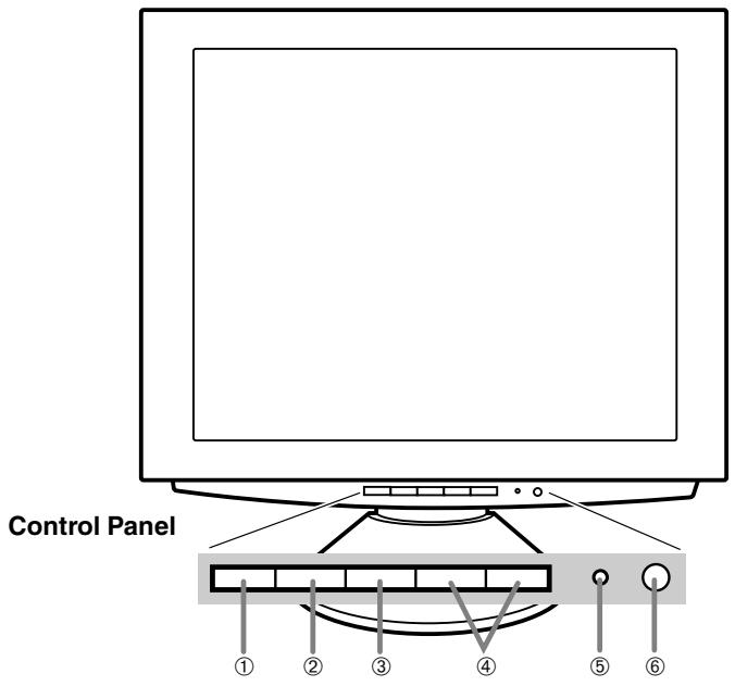
Front view
- INPUT button
- MENU button
- SELECT button
- buttons
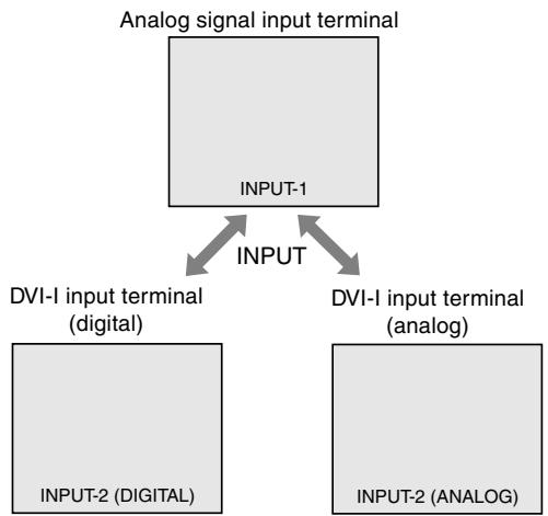
To switch between the signal's input terminals. (Analogue signal input terminal DVI-I input terminal)
This button is used to pop-up, select and close the OSD Menu.
This button is used to select menu options when the OSD Menu is displayed.
When the On Screen Display (OSD) Menu is displayed:
These buttons are used to increase or decrease the value of a selected option.
When the OSD Menu is not displayed:
These buttons are used to adjust backlight brightness .
- Power LED
- Power button
This LED is lit green when in use and orange when in power-saving mode.
Pressing this button turns the power on. (After turning the power on, it may take a little time before the screen displays.)
Press the button again to turn the power off.
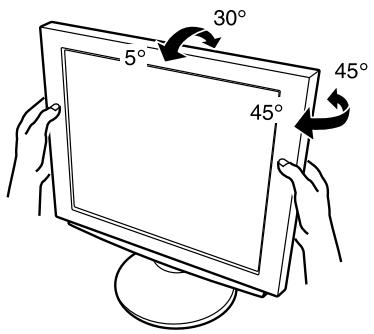
Adjusting the angle of the monitor
Lightly holding both sides of the monitor, adjust it to a suitable viewing angle.
CAUTION!
- Pressure from hands on the LCD panel could cause damage.
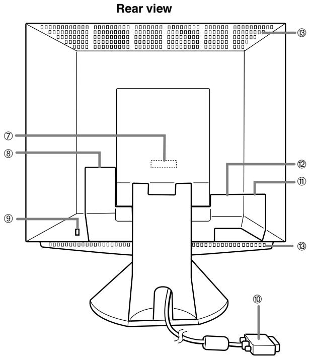
- Analog signal input terminal
- Power terminal
- Security lock anchor
- Analog signal cable
11.USB port
12.DVI-I input terminal
Remove the cover to see the analog signal input terminal. At the time of leaving the factory the analog signal cable is connected.
Remove the cover to see the power terminal. The AC adapter is connected here.
By connecting a security lock (purchased separately) to the security lock anchor, the monitor is fixed so that it cannot be transported.
The security slot works in conjunction with Kensington Micro Saver Security Systems.
Connects to the computer's analog RGB output terminal.
Remove the cover to see the USB port (upstream: 1 port, downstream: 2 ports).
Remove the cover to locate the digital/analogue signal input terminal (DVI-I29 pin). The computer's digital RGB output terminal or analogue RGB output terminal can be connected here.
For a digital signal input: It can be connected to a computer with a DVI-compatible output terminal (DVI-D24 pin or DVI-I29 pin) and which has SXGA output ability. Depending on the computer to be connected, correct display may or may not be possible.
To be able to connect, a cable that is to be purchased separately is required.
To connect to a digital RGB output terminal: Digital signal cable (model name: NL-C01E)
To connect to an analogue RGB output terminal: Analogue signal cable (model name: NL-C02E)
Note: Never block the ventilation openings as this may lead to overheating inside the monitor and result in malfunction.
- Ventilation openings
Connecting the monitor and turning the monitor on and off
Connecting the monitor to a power source
Use only the AC adapter supplied.
Notes:
-
Do not overly bend the cable or add extension cords as this could lead to malfunction.
-
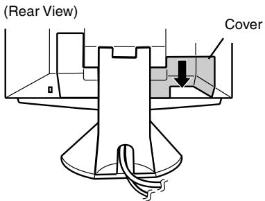
Remove the stand cover.
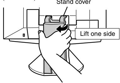
(Rear View)
- Remove the cover.
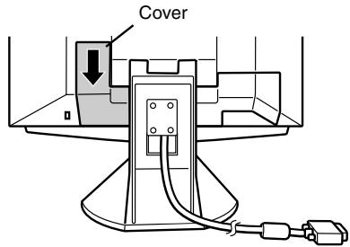
- Connect the AC adapter to the monitor's power terminal.
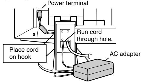
- Replace cover.
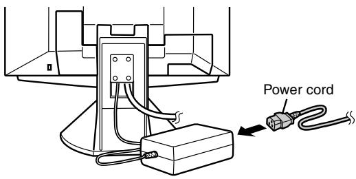
- Connect power cord to AC adapter.
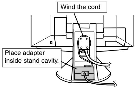
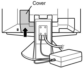
Fitting the AC adapter inside the stand
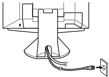
- Replace stand cover.
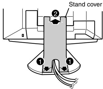
- Place power plug into AC outlet.
Connecting the monitor to a computer (PC etc.)
Connect using this device's analogue signal cable
Connect this device's analogue signal cable to the computer (PC etc.).
When connecting, ensure that both the monitor and computer are switched off.
Be careful not to overly bend the cable or add extension cords as this could lead to malfunction.
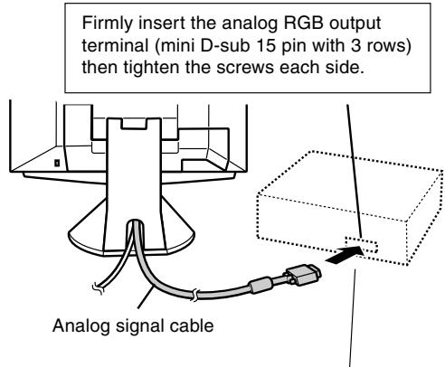
If connecting to a D-sub 15 pin 2 row Apple Power Macintosh, attach a Macintosh conversion adapter (to be purchased separately) to the analog signal cable.
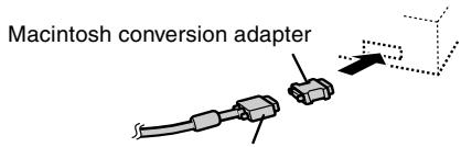
Analog signal cable
After connecting the adapter, tighten the screws on each side to fix into place.
Note:
- If connecting to the Sun Ultra series, a conversion adapter (purchased separately) may be required.
Connect using a display cable (to be purchased separately)
Using a display cable (to be purchased separately), it can be connected to the computer's (PC etc.) digital RGB output terminal or analogue RGB output terminal.
To connect to a digital RGB output terminal: Digital signal cable (model name: NL-C01E)
- To connect to an analogue RGB output terminal: Analogue signal cable (model name: NL-C02E)
- For a digital signal input: It can be connected to a computer with a DVI-compatible output terminal (DVI-D24 pin or DVI-I29 pin) and which has SXGA output ability. Depending on the computer to be connected, correct display may or may not be possible.
- Be careful not to overly bend the cable or add extension cords as this could lead to malfunction.
1. Remove the cover (Rear View)
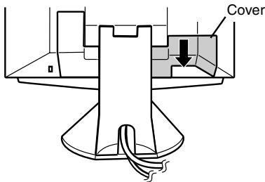
- Connect the display cable (to be purchased separately) into the DVI-I input terminal.
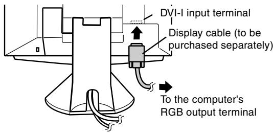
- Replace the cover.
Connecting a USB device
This monitor can be used with hubs which use the USB standard (Rev. 1.1).
Downstream (2 ports)
USB devices such as keyboard and mouse can be connected here. Up to 100mA of power is able to be supplied per port. Devices requiring more than 100mA cannot be connected.
Upstream (1 port)
USB compatible computers and self-powered hubs can be connected. (Bus-powered hubs cannot be connected.)
Notes:
If a USB cable is required, please use the one included.
- Before connecting, ensure that the shape of the USB cable connector is correct.
- For information regarding the USB function (such as set-up) please refer to the operation manual of the computer to be connected.
- Some computers, OS and other devices may not be able to be activated. To ascertain a certain device's USB compatibility, please contact the manufacturer of the device.
1. Remove the cover.
2. Connect the USB cable.
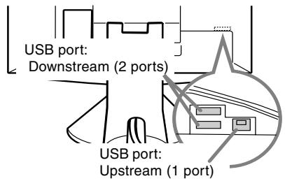
3. Replace the cover.
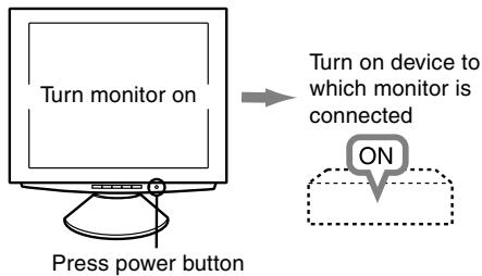
Turning the power on
- Press the monitor's power button.
- Turn on the computer.
The power LED will be lit green, and the screen will display an image.
Changing between input terminals
Use the INPUT button to switch between signal input terminals.
Notes:(when using an analog signal)
- If using the monitor for the first time or after having changed the system settings during use, perform an automatic screen adjustment (p. 19).
- When connecting to a notebook, if the notebook computer's screen is set so that it is displaying at the same time, the MS-DOS screen may not be able to display properly. In this case, change the settings so that only the monitor is displaying.
Connecting the monitor and turning the monitor on and off
Installing set-up information and the ICC profile (Windows)
Depending on the computer or OS, it may be necessary to use the computer to operate the installation of monitor set-up information etc. If so, follow the steps below to install the monitor set-up information. (Depending on the type of computer or OS, command names and methods may differ. Please follow the computer's own operation manual while reading this.)
About the ICC profile
An ICC (International Color Consortium) profile is a file that describes the color characteristics of the LCD monitor. By using an application that works together with an ICC profile, a high color resolution can be realized.
- Windows98, WindowsMe and Windows2000 all use the ICC profile.
- When installing Windows98, WindowsMe and Windows2000 set-up information (described below), the ICC profile is also installed. If you would like to install the ICC program only, please refer to Installing the ICC profile on page 16.
- When using the ICC profile, please set the [WHITE BALANCE] to [STD] and the [COLOR MODE] to [STD].
For Windows95
Installing monitor set-up information into Windows95. This explanation assumes that the floppy disk drive is "A drive".
- Place the Utility Disk (provided) into the computer's A drive.
- Click on the [Start] button. From [Settings], choose [Control Panel].
- Double click on [Display].
- Click on [Settings], [Advanced Properties], and [Monitor], then [Change].
- Click on [Have disk], confirm that [Copy manufacturer's files from:] is [A:] then click [OK].
- Confirm that the monitor details are selected, and click [OK].
- Check that the monitor details are displayed, then click [Apply].
- Click [OK], and close the window.
- Remove the Utility Disk from the A drive.
For Windows98
Installing monitor set-up information into Windows98, and setting the monitor's ICC profile as a predetermined value.
This explanation assumes that the floppy disk drive is "A drive".
If the "Add new Hardware Wizard" has appeared:
- Place the Utility Disk (provided) into the computer's A drive.
- Click [Next].
- Check [Display a list of all the drivers in a specific location, so you can select the driver you want.], then click [Next].
- When [Models] is displayed, click on [Have disk], confirm that [Copy manufacturer's files from:] is [A:], and click [OK].
- Confirm that the monitor details are selected, then click [Next], [Next], and [Finish]. If the "Add New Hardware Wizard" appears, repeat the installation commands beginning from 2 above.
- Remove the Utility Disk from the A drive.
If the "Add New Hardware Wizard" has not appeared:
- Place the Utility Disk in the computer's A drive.
- Click on the [Start] button. From [Settings], choose [Control Panel].
- Double click on [Display].
- Click on [Settings], [Advanced] and [Monitor].
- In [Options], check [Automatically detect Plug & Play monitors] and click on [Change].
- Click [Next].
- Click on [Display a list of all the drivers in a specific location, so you can select the driver you want]. then click [Next].
- When [Models] is displayed, click on [Have disk], confirm that [Copy manufacturer's files from:] is [A:], and click [OK].
- Confirm that the monitor details are selected, then click [Next], [Next], and [Finish].
- Check that the monitor details are displayed, then click [Apply].
- Click [OK], and close the window.
- Remove the Utility Disk from the A drive.
Connecting the monitor and turning the monitor on and off
For Windows2000
Installing monitor set-up information into Windows2000, and setting the monitor's ICC profile as a predetermined value.
This explanation assumes that the floppy disk drive is "A drive".
- Place the Utility Disk (provided) into the computer's A drive.
- Click on the [Start] button. From [Settings], choose [Control Panel].
- Double click on [Display].
- Click on [Settings], [Advanced] and [Monitor].
- Click on [Properties], [Driver] and [Update Driver].
- When [Upgrade Device Driver Wizard] appears, click [Next].
- Check [Display a list of the known drivers for this device so that I can choose a specific driver] and click [Next].
- When [Models] is displayed, click on [Have disk], confirm that [Copy manufacturer's files from:] is [A:], and click [OK].
- Select the monitor from the list displayed and click [Next].
- Click [Next], confirm that the monitor's name appears on the screen, and click [Finish]. If [The Digital Signature Not Found] appears, click [Yes].
- Click on [Close].
- Click [OK], and close the window.
- Remove the Utility Disk from the A drive.
For WindowsMe
Installing monitor set-up information into
WindowsMe, and setting the monitor's ICC profile as a predetermined value.
This explanation assumes that the floppy disk drive is "A drive".
If the "Add new Hardware Wizard" has appeared:
- Place the Utility Disk (provided) into the computer's A drive.
- Check [Specify the location of the driver [Advanced]] and click [Next].
- Check [Display a list of all the drivers in a specific location, so you can select the driver you want]. then click [Next].
-
When [Models] is displayed, click on [Have disk], confirm that [Copy manufacturer's files from:] is [A:], and click [OK].
-
Select the monitor details from the list, then click [Next], [Next], and [Finish]. If the "Add new Hardware Wizard" appears, repeat the installation commands beginning from 2 above.
- Remove the Utility Disk from the A drive.
If the "Add New Hardware Wizard" has not appeared:
- Place the Utility Disk in the computer's A drive.
- Click on the [Start] button. From [Settings], choose [Control Panel].
- Double click on [Display].
- Click on [Settings], [Advanced] and [Monitor].
- In [Options], check [Automatically detect Plug & Play monitors] and click on [Change].
- Check [Specify the location of the driver [Advanced]] and click [Next].
- Check [Display a list of all the drivers in a specific location, so you can select the driver you want.] and click [Next].
- When [Models] is displayed, click on [Have disk], confirm that [Copy manufacturer's files from:] is [A:], and click [OK].
- Select the monitor details, then click [Next], [Next], and [Finish].
- Check that the monitor details are displayed, then click [Apply].
- Click [OK], and close the window.
- Remove the Utility Disk from the A drive.
Installing the ICC profile
Installing the monitor's ICC profile. (If the set-up information has already been installed, so too has the profile, and there is no need to install it.) This explanation assumes that the floppy disk drive is "A drive".
- Place the Utility Disk in the computer's A drive.
- Click on the [Start] button. From [Settings], choose [Control Panel].
- Double click on [Display].
- Click on [Settings] and [Advanced].
- Click on [General] and from [Compatibility] select [Apply the new display setting without restarting], then click on [Color Management].
- Click [Add], and select [312 Floppy [A:]] as the file location.
- Choose the color profile that you would like to install, and click on [Add].
- Choose the profile and click on [Set As Default].
-
Click [OK], and close the window.
10.Remove the Utility Disk from the A drive. -
When using the ICC profile, please set the [WHITE BALANCE] to [STD] and the [COLOR MODE] to [STD].
Information about the ColorSync profile (MacOS)
About the ColorSync profile
ColorSync is the Apple Corporation's color management system and is a function that enables color resolution to be realized when used with a compatible application. A ColorSync profile describes the color characteristics of the LCD monitor.
Notes:
- This monitor's ColorSync profile works with MacOS8.5 or above.
- When using the ColorSync profile, please set the [WHITE BALANCE] to [STD] and the [COLOR MODE] to [STD].
Setting up the ColorSync profile
Notes:
-
A floppy disk drive is necessary. In addition, it is necessary to have PC Exchange or File Exchange installed in your system.
Depending on the type of computer or OS, command names and methods may differ. Please follow the computer's own operation manual while reading this. -
Place the Utility Disk (provided) into the computer's floppy disk drive.
- Copy the profile to be used from the Mac folder on the Utility Disk to the ColorSync profile folder located within the system folder.
- Using the ColorSync on the control panel, choose the profile to be used.
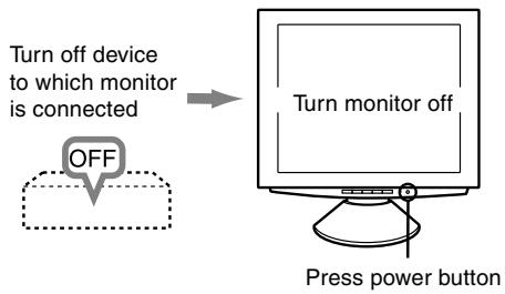
Turning the power off
- Turn the computer off.
- Press the monitor's power button. The Power LED will disappear. If the monitor is not going to be used for a long period of time, be sure to unplug it from the AC outlet.
Adjusting the screen display
For analog signal
- First perform an automatic adjustment. (p. 19)
- Perform manual adjustment where necessary. (p. 20)
For digital signal
The monitor can generally be used without adjustment. If necessary perform manual adjustment. (p. 23)
Note:
- All adjustments will be saved even after turning the power off.
Adjusting the backlight
The backlight brightness can be adjusted.
Carry out the commands without the On Screen Display (OSD) Menu displayed. If the OSD Menu is displayed, press the MENU button (several times may be required) and begin when the OSD Menu has disappeared.
- Without the OSD Menu being displayed, push the or the button. At the bottom of the screen the BRIGHT bar will appear.
BRIGHT
31
- Adjust by pressing the button (darker) or button (lighter).
The BRIGHT bar automatically disappears approximately 5 seconds after the last command.
ADJUSTMENT menu reset
The adjustment values of the analogue signal time's ADJUSTMENT menu can be returned to their original ex-factory values.
- Turn on the monitor power.
- Press the MENU button and the button simultaneously. When [RESET] appears on the screen, the reset is complete.
Resetting all adjustment values
All adjustment values can be returned to their original ex-factory values in one command.
- Turn off the monitor power.
- Press the MENU button and the SELECT button simultaneously, and while doing this press the power button (i.e. turn the power on). When [ALL RESET] appears on the screen, the reset is complete.
Note:
- While ALL RESET is displayed, the control buttons are disabled.
- It is not possible to reset values when the adjustment lock is in place. Remove the adjustment lock before attempting to operate control buttons.
Adjustment lock function
By disabling the control buttons (i.e. setting the lock) any attempted changes to adjusted values will be voided.
- Turn off the monitor power.
- While pressing the MENU button, press the power button (i.e. turn the power on). Continue to press the button until the message appears on the screen.
When the menu is unlocked: [ADJUSTENT LOCKED] will appear on the screen, and the lock will be set.
When the menu is locked: [ADJUSTENT UNLOCKED] will appear on the screen, and the lock will be removed.
Note:
- When the lock is in place, all buttons other than the power button are disabled.
Choosing a message language
Messages displayed on the screen and OSD Menu contents can be changed to the following languages. Dutch, English, French, German, Spanish, Italian, Swedish.
- Turn off the monitor.
- Pressing the and buttons simultaneously, press the power button (i.e. turn the power on). The Language Selection Menu (LANGUAGE) will be displayed on the screen.
- Use the SELECT button to choose a language.
- Press the MENU button. The setting is complete. From now, messages and adjustment menus will be displayed in the chosen language.
Note:
- The language selection menu disappears approximately 30 seconds after the last command has been made.
Automatic screen adjustment
Options in the ADJUSTMENT Menu can be adjusted automatically (CLOCK, PHASE, H-POS V-POS).
Note:
- When setting up this monitor for the first time or after having changed an aspect of the current system, perform an automatic screen adjustment before use.
- First display an image that makes the entire screen very bright. If you are using Windows, you can use the Adjustment Pattern on the accompanying Utility Disk (right column).
- Press the MENU button. The ADJUSTMENT Menu will be displayed.
- Press the button.
The screen will become dark and [ADJUSTING] will be displayed. After a few seconds the ADJUSTMENT Menu will return. (The automatic adjustment is now complete.)
- Press the MENU button 4 times to make the OSD Menu disappear.
Notes:
- In most cases automatic adjustment is sufficient.
-
If necessary due to any of the following, manual adjustments (p. 20) can be performed after the automatic adjustment.
-
When further fine adjustment is needed.
- When the computer's video input signals are Composite Sync or Sync On Green. (Automatic adjustments may not be possible.)
- When [OUT OF ADJUST] is displayed. (When the screen displays an entirely dark image, the automatic screen adjustment may be disabled. When making an automatic adjustment, be sure to either use the Adjustment Pattern or try displaying an image that makes the entire screen very bright.)
Opening the Adjustment Pattern (for Windows)
If you are using Windows, you can use the Adjustment Pattern (for Windows) on the accompanying Utility Disk.
This explanation is for Windows 95/98/Me/2000, and assumes that the floppy disk drive is "A drive".
- Place the Utility Disk (provided) into the computer's A drive.
- Open [My Computer] and select [312 Floppy [A:]]. If using Windows 3.1, open [File Manager] and choose "A drive".
- Double click on [Adj_uty.exe] to run the Adjustment Program. The Adjustment Pattern will appear.
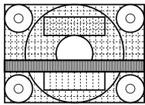
Adjustment pattern
Notes:
After completing the adjustments, press the computer's [Esc] key to exit the Adjustment Program.
- If the floppy disk drive of your computer is not "A drive", please read the below substituting the floppy disk drive you are using in place of "A drive" or "A".
- If your computer's display mode is set to 65K colors, you may see the different color levels in each color pattern or the gray scale may look colored. (This is due to the specification of the input signal and is not a malfunction.)
Adjusting the screen display (when using an analog signal)
Manual screen adjustment
Adjustments can be made using On Screen Display (OSD) Menu provided.
- Display an image that makes the entire screen very bright. If using Windows, you can open and use the Adjustment Pattern on the accompanying Utility Disk. (p. 19)
- Press the MENU button. The ADJUSTMENT Menu will be displayed.
At this point relevant menu options can be adjusted.
Each time the MENU button is pressed the next menu is selected. (ADJUSTMENT GAIN CONTROL WHITE BALANCE MODE SELECT OSD Menu disappears)
Notes:
- The OSD Menu automatically disappears approximately 30 seconds after the last command.
- This explanation is based on using the Adjustment Pattern (for Windows) to make adjustments.
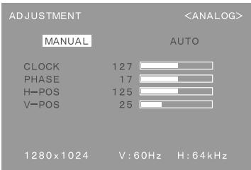
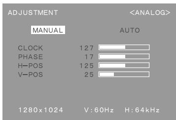
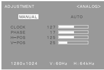
ADJUSTMENT Menu
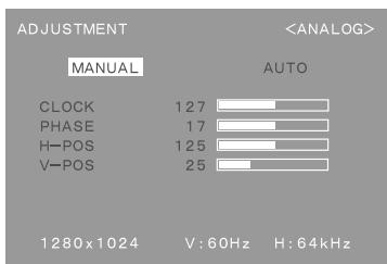
MANUAL: Individual menu options are manually adjusted.
AUTO: Every menu option is automatically adjusted.
Notes:
- Press the button to select [AUTO].
- To choose a menu option: SELECT button
- To go to the next menu: MENU button
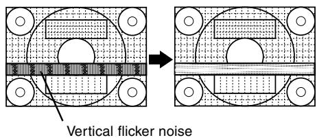
CLOCK
The figure below demonstrates how to adjust so that vertical flicker noise is not emitted. (▲▶ buttons)
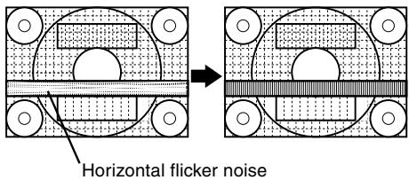
PHASE
The figure below demonstrates how to adjust so that horizontal flicker noise is not emitted. (▲▶ buttons)
Note:
- Adjustments to PHASE should be made only after CLOCK has been correctly set.
H-POS (horizontal positioning) and V-POS (vertical positioning)
To center the screen image within the boundaries of the screen, adjust the left-right (H-POS) values and the up-down (V-POS) values. (▲▶ buttons)
Adjusting the screen display (when using an analog signal)
GAIN CONTROL Menu
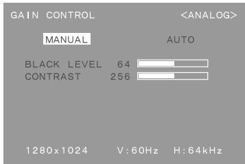
MANUAL: Individual menu options are manually adjusted.
AUTO: Every menu option is automatically adjusted using the Auto Gain Control* function,
Notes:
- Press the button to select [AUTO].
- To choose a menu option: SELECT button
-
To go to the next menu: MENU button
-
Auto Gain Control function
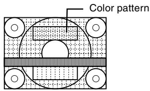
- The Auto Gain Control adjusts contrast and black level based on the brightest color of the image displayed. If you are not using the Adjustment Pattern it is necessary to have an area of 5mm × 5mm of white displayed, and if not adjustments may not be possible. (In such case, [OUT OF ADJUST] will appear and setting values remain unchanged.)
- If the signal coming from the computer is composite sync or sync on green, automatic adjustment cannot be performed. Please perform manual adjustment instead.
BLACK LEVEL
Total screen brightness can be adjusted while watching the color pattern. (▲▶ buttons)
CONTRAST
While watching the color pattern, adjustments can be made so that all graduations appear. (▲▶ buttons)
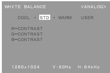
WHITE BALANCE Menu
Notes:
- On settings other than [STD] not all graduations can be displayed. To display all graduations, set to [STD].
- Use the buttons to select [COOL], [·], [STD], [·], [WARM] or [USER].
- Selecting USER will display the setting values for [R-CONTRAST], [G-CONTRAST] and [B-CONTRAST], in order to make fine adjustments.
- Use the SELECT button to select [R-CONTRAST], [G-CONTRAST] and [B-CONTRAST].
- To go to the next menu: MENU button
COOL . . . Color tone bluer than standard
Color tone slightly bluer than standard
STD.......Color tone standard setting
Color tone slightly redder than standard
WARM . . . Color tone redder than standard
USER
R-CONTRAST... button for blue-green
button for red
G-CONTRAST . . button for purple
button for green
B-CONTRAST... button for yellow
button for blue
Adjusting the screen display (when using an analog signal)
MODE SELECT Menu

Notes:
Depending on the resolution of the input signal, even if menu options can be selected, the display may not change.
- To choose a menu option: SELECT button
- When adjustment complete: MENU button
OSD H-POSITION (OSD horizontal position)
The position of the OSD display can be moved to the left and right. (▲▶ buttons)
OSD V-POSITION (OSD vertical position)
The position of the OSD display can be moved up and down. (▶ buttons)
INPUT (Input mode)
The input mode can be set. (▶ buttons)
VESA: VESA mode
MAC: Power Macintosh mode
400 LINES (degree of resolution)
You can specify the horizontal resolution of a 400-line screen when using US text, etc.
(▲▶buttons)
640: 640 X 400 dot mode
720: 720 X 400 dot mode (US text etc.)
Note:
- As the resolution input for other than 400 lines is done automatically, there is no need to set it.
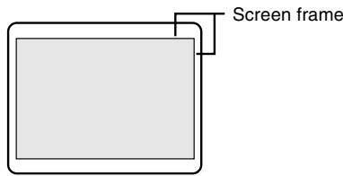
EXPAND (Screen expansion)
For display modes of less than 1280 X 1024 pixels, the display can be expanded if desired. (▲▶ buttons)
OFF: Expansion off
ON1: Using the fixed aspect ratio, the entire screen is enlarged.
ON2: The entire screen is enlarged.
Note:
- If a resolution of 1280 × 1024 pixels cannot be achieved even after expansion is attempted, the screen's perimeter will display black. (This is not a malfunction.)
SCALING (Level of scaling)
If [EXPAND] is set on [ON1] or [ON2], the sharpness of the image can be adjusted. (▲▶ buttons)
Note:
- If [EXPAND] is set on [OFF], [SCALING] cannot be adjusted.
COLOR MODE
If this is set on [STD], the original color scheme of the LCD monitor will be displayed. If this is set on [sRGB], the colors of will be corrected according to the computer image. (▲▶ buttons)
Note:
- To set [COLOR MODE] to [sRGB], set the [WHITE BALANCE] to [STD].
Manual screen adjustment
Adjustments can be made using the On Screen Display (OSD) Menu provided.
- Display an image that makes the entire screen very bright. If using Windows, you can open and use the Adjustment Pattern on the accompanying Utility Disk. (p. 19)
- Press the MENU button. The WHITE BALANCE Menu will be displayed.
At this point relevant menu options can be adjusted.
Each time the MENU button is pressed the next menu is selected. (WHITE BALANCE MODE SELECT OSD Menu disappears)
Notes:
- The OSD Menu automatically disappears approximately 30 seconds after the last command.
- This explanation is based on use of the Adjustment Pattern (for Windows) to make adjustments
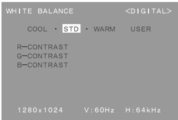
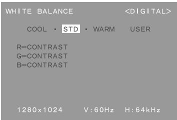
WHITE BALANCE Menu
Notes:
- On settings other than [STD] not all graduations can be displayed. To display all graduations, set to [STD].
- Use the buttons to select [COOL], [·], [STD], [·], [WARM] or [USER].
- Selecting USER will display the setting values for [R-CONTRAST], [G-CONTRAST] and [B-CONTRAST], in order to make fine adjustments.
- Use the SELECT button to select [R-CONTRAST], [G-CONTRAST] and [B-CONTRAST].
- To go to the next menu: MENU button
COOL . . . Color tone bluer than standard
Color tone slightly bluer than standard
STD.......Color tone standard setting
Color tone slightly redder than standard
WARM . . . Color tone redder than standard
USER
R-CONTRAST... button for blue-green
button for red
G-CONTRAST . . button for purple
button for green
B-CONTRAST... button for yellow
button for blue
Adjusting the screen display (when using a digital signal)
MODE SELECT Menu
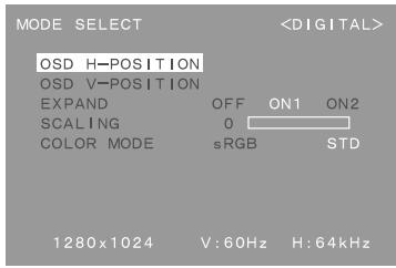
COLOR MODE
If this is set on [STD], the original color scheme of the LCD monitor will be displayed. If this is set on [sRGB], the colors of will be corrected according to the computer image. (▲▶ buttons)
Note:
- To set [COLOR MODE] to [sRGB], set the [WHITE BALANCE] to [STD].
Notes:
Depending on the resolution of the input signal, even if menu options can be selected, the display may not change.
- To choose a menu option: SELECT button
- When adjustment complete: MENU button
OSD H-POSITION (OSD horizontal position)
The position of the OSD display can be moved to the left and right. (▲▶ buttons)
OSD V-POSITION (OSD vertical position)
The position of the OSD display can be moved up and down. (▲▶ buttons)
EXPAND (Screen expansion)
For display modes of less than 1280 X 1024 pixels, the display can be expanded if desired. (▲▶ buttons)
OFF: Expansion off
ON1: Using the fixed aspect ratio, the entire screen is enlarged.
ON2: The entire screen is enlarged.
Note:
- If a resolution of 1280 × 1024 pixels cannot be achieved even after expansion is attempted, the screen's perimeter will display black. (This is not a malfunction.)
SCALING (Level of scaling)
If [EXPAND] is set on [ON1] or [ON2], the sharpness of the image can be adjusted. (▲▶ buttons)
Note:
- If [EXPAND] is set on [OFF], [SCALING] cannot be adjusted.
Monitor care
Always remove the plug from the AC outlet when cleaning the monitor.
Cabinet and control panel section
Use a soft dry cloth to lightly wipe away any grime from the cabinet and control panel.
If they are very dirty, apply neutral detergent to a dampened soft cloth, wring it out well and wipe away grime.
LCD panel section
Use a soft dry cloth to lightly wipe away dirt and dust from the surface of the LCD panel. (A soft cloth such as gauze or that used for lens cleaning is suitable.)
CAUTION!
- Never use thinner, benzine, alcohol, glass cleaner, etc, as this could lead to color change or change in shape.
- Never scratch the monitor with anything hard or apply strong pressure as this could leave marks or result in malfunction.
Storage
If the monitor will not be used for a long period of time, be sure to remove the power plug from the AC outlet.
CAUTION!
Do not leave the monitor in contact with rubber or plastic items for long periods of time as this could lead to color change or change in shape.
Troubleshooting
If you think the monitor may be faulty, please check the following points before taking it to be repaired. If afterwards it still does not work, please contact the shop where you purchased the monitor or your nearest Sharp authorized Service Center.
The monitor's fluorescent tubes have a limited life span.
- If the screen darkens, persistently flickers or does not light up, it may be necessary to replace the fluorescent tube unit. Please inquire at the shop where you purchased the monitor or your nearest Sharp authorized Service Center. (Never attempt this replacement on your own.)
In the initial period of use, due to the characteristics of fluorescent tubes the screen may flicker. (This is not a malfunction.) Should this happen, check by first turning off the power, then turning it on again.
No image appears on the monitor (Power LED is not lit)
- Are the AC adapter and power cord connected properly? (p. 12)
No image appears on the monitor (Power LED is lit)
Is the computer connected properly? (p. 13)
Is the computer turned on?
Is the signal's input terminal switched to the correct one? (p. 14)
- Does the computer's signal timing correspond to monitor specifications? (p. 27)
Is the computer in power-saving mode?
Control buttons do not work
Is the adjustment lock on? (p. 18)
Only VGA image is displayed
- Does the Windows display timing setting meet monitor specifications? Refer to the monitor signal timings (p. 27) and set to appropriate timing.
The image appears distorted
- Does the computer's signal timing correspond to monitor specifications? (p. 27)
If you are using the analog signal, perform automatic adjustment. (p. 19) - If you can change the frequency on the computer you are using, change the values to a low frequency count.
Product specifications
LCD display
18.1 inches (46 cm measured diagonally)
Super-V and Anti Glare Low Reflection TFT LCD module
Resolution (max.)
SXGA 1280 x 1024 pixels
Displayable colors (max.)
16.77 million colors (8 bit)
Brightness (max.)
200cd/m²
Dot pitch
0.2805(H) 0.2805(V) mm
Contrast ratio
350:1
Angle of visibility
Left-right 150^ ; Up-down 150^
Screen display size
Horizontal 359 mm x Vertical 287.2 mm
Video signal
Analog: Analog RGB (0.7Vp-p) [75Ω]
Digital: DVI standard based on 1.0
Sync signal
Separate Sync (TTL level: +/-), Sync on
Green, Composite Sync (TTL level: +/-)
Expansion compensation
Digital screening (enlargement of display to correct VGA/SVGA/XGA)
[1:1, expansion (fixed aspect ratio), expansion
(total screen surface)]
Plug & Play
VESA: DDC1/DDC2B compatible
Power management
VESA: based on DPMS
DVI: based on DMPM
Input signal terminal
1 upstream port, 2 downstream ports (bus-powered hub based on USB standard Rev 1.1)
Screen tilt
Upward 0^ -30°; downward 0^ - 5°
Screen swivel
90^ from left through right
Power supply
AC100-240V, 50/60Hz (Use special AC adapter,
type NL-A03E of Sharp Corporation.)
Temperature of operating environment 5 - 35°C
Power consumption
Maximum 44W (3.2W when in power-saving mode)
(Use special AC adapter.)
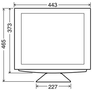
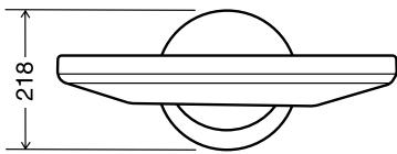
Dimensions (W× D× H)
443 mm x 218 mm x 465 mm
Weight (excluding AC adapter)
Approx. 10.1kg
Display area only, approx. 7.8kg
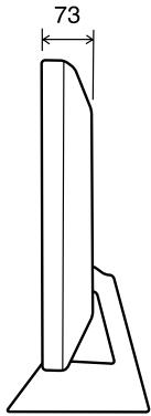
Dimensions (Units: mm)
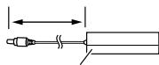
Length of analog signal cable: approx. 2.0m^*
Length of USB cable included: approx. 1.8 m
*Length from analog signal input terminal
Special AC adapter
Approx. 2.0m
Approx. H 120 mm x D 60 mm x H 35 mm
Digital signal cable (NL-C01E): Approx. 2.0 m
Analogue signal cable (NL-C02E): Approx. 2.0 m
Relevant signal timings (analog)
| Display mode | Hsync (kHz) | Vsync (Hz) | Dot fre- quency (MHz) | |
| VESA | 640x480 | 31.5kHz | 60Hz | 25.175MHz |
| 37.9kHz | 72Hz | 31.5MHz | ||
| 37.5kHz | 75Hz | 31.5MHz | ||
| 43.3kHz | 85Hz | 36.0MHz | ||
| 640x400 | 37.9kHz | 85Hz | 31.5MHz | |
| 720x400 | 37.9kHz | 85Hz | 35.5MHz | |
| 800x600 | 35.1kHz | 56Hz | 36.0MHz | |
| 37.9kHz | 60Hz | 40.0MHz | ||
| 48.1kHz | 72Hz | 50.0MHz | ||
| 46.9kHz | 75Hz | 49.5MHz | ||
| 53.7kHz | 85Hz | 56.25MHz | ||
| 1024x768 | 48.4kHz | 60Hz | 65.0MHz | |
| 56.5kHz | 70Hz | 75.0MHz | ||
| 60.0kHz | 75Hz | 78.75MHz | ||
| 68.7kHz | 85Hz | 94.5MHz | ||
| 1152x864 | 67.5kHz | 75Hz | 108.0MHz | |
| 1280x960 | 60.0kHz | 60Hz | 108.0MHz | |
| 1280x1024 | 64.0kHz | 60Hz | 108.0MHz | |
| 80.0kHz | 75Hz | 135.0MHz | ||
| US text | 720x400 | 31.5kHz | 70Hz | 28.3MHz |
| Power Macintosh series | 640x480 | 35.0kHz | 66.7Hz | 30.2MHz |
| 832x624 | 49.7kHz | 74.6Hz | 57.3MHz | |
| 1024x768 | 60.2kHz | 75Hz | 80.0MHz | |
| 1152x870 | 68.7kHz | 75Hz | 100.0MHz | |
| Sun Ultra series | 1024x768 | 48.3kHz | 60Hz | 64.13MHz |
| 53.6kHz | 66Hz | 70.4MHz | ||
| 56.6kHz | 70Hz | 74.25MHz | ||
| 1152x900 | 61.8kHz | 66Hz | 94.88MHz | |
| 71.8kHz | 76.2Hz | 108.23MHz | ||
| 1280x1024 | 71.7kHz | 67.2Hz | 117.01MHz | |
| 81.1kHz | 76Hz | 134.99MHz | ||
- All are compliant only with non-interlaced.
- Frequencies for Power Macintosh and the Sun Ultra series are reference values. To connect, another adapter (purchased separately) may be required.
- If the monitor is receiving timing signals that are not compatible, [OUT OF TIMING] will appear. Follow your computer's instruction manual to set the timing so that it is compatible with the monitor.
- If the monitor is not receiving any signal (synch signal), [NO SIGNAL] will appear.
Relevant signal timings (digital)
| Display mode | Hsync (kHz) | Vsync (Hz) | Dot fre-quency (MHz) | |
| VESA | 640x480 | 31.5kHz | 60Hz | 25.175MHz |
| 37.9kHz | 72Hz | 31.5MHz | ||
| 37.5kHz | 75Hz | 31.5MHz | ||
| 800x600 | 37.9kHz | 60Hz | 40.0MHz | |
| 48.1kHz | 72Hz | 50.0MHz | ||
| 46.9kHz | 75Hz | 49.5MHz | ||
| 1024x768 | 48.4kHz | 60Hz | 65.0MHz | |
| 56.5kHz | 70Hz | 75.0MHz | ||
| 60.0kHz | 75Hz | 78.75MHz | ||
| 1152x864 | 67.5kHz | 75Hz | 108.0MHz | |
| 1280x960 | 60.0kHz | 60Hz | 108.0MHz | |
| 1280x1024 | 64.0kHz | 60Hz | 108.0MHz | |
| US text | 720x400 | 31.5kHz | 70Hz | 28.3MHz |
- All are compliant only with non-interlaced.
- A computer with an output terminal conforming to DVI (DVI-D24 pin or DVI-I29 pin) and with SXGA output capability can be connected here. Depending on the type of computer to be connected, the display may not work correctly. In order to connect, it is necessary to purchase a digital signal cable (model name: NL-C01E) separately.
- If the monitor is receiving timing signals that are not compatible, [OUT OF TIMING] will appear. Follow your computer's instruction manual to set the timing so that it is compatible with the monitor.
If the monitor is not receiving any signal (synch signal), [NO SIGNAL] will appear.
The analog signal input connector pin
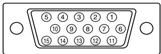
(Mini D-sub connector with 15 pins)
| Number | Function |
| 1 | Red video signal input |
| 2 | Green video signal input |
| 3 | Blue video signal input |
| 4 | GND |
| 5 | GND |
| 6 | For red video signal GND |
| 7 | For green video signal GND |
| 8 | For blue video signal GND |
| 9 | DDC/VCC |
| 10 | GND |
| 11 | N.C. |
| 12 | DDC data |
| 13 | For Hsync signal input |
| 14 | For Vsync signal input |
| 15 | DDC clock |
The DVI-I input connector pin
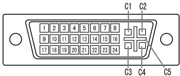
(DVI-I connector with 29 pins)
| No. | Function | No. | Function |
| 1 | TMDS data 2- | 16 | Hot plug detection |
| 2 | TMDS data 2+ | 17 | TMDS data 0- |
| 3 | TMDS data 2/4 shield | 18 | TMDS data 0+ |
| 4 | N.C. | 19 | TMDS data 0/5 shield |
| 5 | N.C. | 20 | N.C. |
| 6 | DDC clock | 21 | N.C. |
| 7 | DDC data | 22 | TMDS clock shield |
| 8 | Analogue vertically synchronised signal | 23 | TMDS clock + |
| 9 | TMDS data 1- | 24 | TMDS clock - |
| 10 | TMDS data 1+ | C1 | Analogue red image signal |
| 11 | TMDS data 1/3 shield | C2 | Analogue green image signal |
| 12 | N.C. | C3 | Analogue blue image signal |
| 13 | N.C. | C4 | Analogue horizontally synchronised signal |
| 14 | +5V | C5 | Analogue GND |
| 15 | GND |
DDC (Plug & Play)
This monitor supports the VESA DDC (Display Data Channel) standard.
DDC is a signal standard for carrying out Plug & Play functions on the monitor or PC. It transfers information such as degree of resolution between the monitor and PC. You can use this function if your PC is DDC compliant and if it is set so that it can detect the Plug & Play monitor.
There are many varieties of DDC due to the differences between systems. This monitor works with DDC1 and DDC2B.
Power management
The monitor is based on the VESA DPMS*1 and the DVI DMPM*2 standards.
To activate the monitor's Power Management function, both the video card and the computer must conform to the VESA DPMS standard and the DVI DMPM standard.
*1 DPMS: Display Power Management Signalling
| DPMS mode | Screen | Power consumption | H-sync | V-sync |
| ON | Display on | 44W | Yes | Yes |
| STANDBY | Display off | 3.2W | No | Yes |
| SUSPEND | Yes | No | ||
| OFF | No | No |
*2 DMPM: Digital Monitor Power Management
| DMPM mode | Screen | Power consumption |
| ON | Display on | 44W |
| OFF | Display off | 3.2W |
Instructions for attaching a VESA compliant arm
An arm or stand based on the VESA standard (purchased separately) can be attached to the monitor.
Procurement of the arm or stand is at the customer's discretion.
Arms or stands able to be used
Attachments must satisfy the following.
Compatible with the VESA standard
- Have a gap of 100 mm × 100 mm between the screw holes on the section to be attached
- Not be likely to fall off or break off after being attached to the monitor.
How to attach the arm or stand

CAUTION!
Be careful not to cut or jam your fingers.
Note:
-
Do not bend the signal cable or the AC adapter cable nor place weight on them. Doing so could lead to damage.
While following these instructions, please also refer to the installation instructions in the operation manual included with the arm or stand -
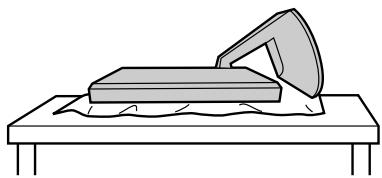
Spread out a soft cloth on a suitable horizontal surface.
- Being careful not to damage the monitor, gently lay the monitor on it display-side down.
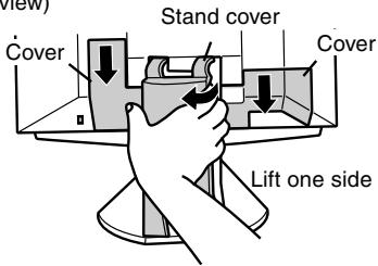
- Remove the stand cover and the covers to the left and to the right.
(Rear view)
- Remove the two screws, and remove the cover.
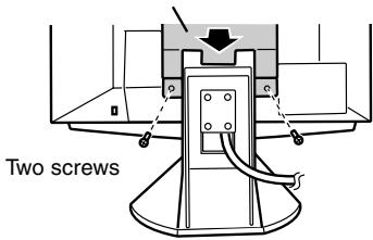
Cover
- Remove the four screws and then remove the stand from the monitor.
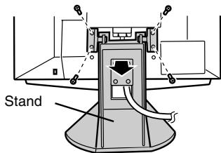
Four screws
- Attach the arm to the monitor with the four screws.
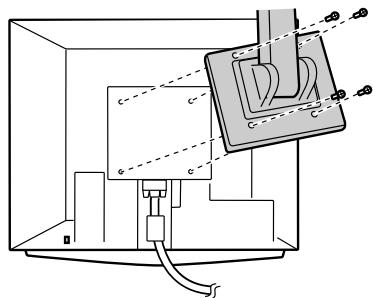
The screws used to attach the arm should be M4 screws with a length of 8mm 10mm protruding from the surface to be attached.
Using different screws could lead to malfunction or may lead to the monitor falling off,internal damaged,personal injury 8 10mm
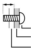
Screw used to attach arm Arm
Part of monitor to which arm is attached
Inhaltsverzeichnis
SHARP ELECTRONICS CORPORATION
Sharp Plaza, Mahwah, New Jersey 07430
TEL:1-800-BE-SHARP

This equipment complies with the requirements of Directives 89/336/EEC and 73/23/EEC as amended by 93/68/EEC.
"WARNING: DIESES GERÄT MUSS GEERDET WERDEN."
LCD-Monitor (1)
-Netzadapter(1)
*1 DPMS: Display Power Management Signalling
*2 DMPM: Digital Monitor Power Management
SHARP ELECTRONICS CORPORATION
Sharp Plaza, Mahwah, New Jersey 07430
TEL:1-800-BE-SHARP

This equipment complies with the requirements of Directives 89/336/EEC and 73/23/EEC as amended by 93/68/EEC.
- REPLACER le couvercle.
Analogue: Analogue RVB (0.7Vp-p) [75Ω]
Dimensions (L x P x H)
443 mm X 218 mm x 465 mm
Câble du signal analogue (NL-C02E): Approx. 2,0 m
*2 DMPM: Digital Monitor Power Management
This equipment complies with the requirements of Directives 89/336/EEC and 73/23/EEC as amended by 93/68/EEC.
Menu ADJUSTMENT (REGOLAZIONE)
VESA Compatible DDC1/DDC2B
1 porta upstream, 2 portedownstream
*1 DPMS: Display Power Management Signalling
*2 DMPM: Digital Monitor Power Management
SHARP ELECTRONICS CORPORATION
Sharp Plaza, Mahwah, New Jersey 07430
TEL:1-800-BE-SHARP

This equipment complies with the requirements of Directives 89/336/EEC and 73/23/EEC as amended by 93/68/EEC.
MAC: Modo Power Macintosh
400 LINES (grado de resolution)
Puede programar la resolution horizontal de una pantalla de 400 lines si utilizes US text, etc.
(botones
640: 640X400dotmode
720: 720 X 400 dot mode (US text etc.)
Nota:
Cable debral digital (NL-C01E): Aprox.2,0 m
Cable de senal analógica (NL-C02E): Aprox. 2,0 m