380-040 - Log splitter Meec Tools - Free user manual and instructions
Find the device manual for free 380-040 Meec Tools in PDF.


| Product Type | Log Splitter |
| Brand | Meec Tools |
| Model | 380-040 |
| Power Source | Gasoline Engine |
| Engine Displacement | 196 cc |
| Max Splitting Force | 15 tons |
| Max Log Length | 25 inches |
| Cycle Time | 13 seconds |
| Hydraulic Oil Capacity | 6.3 quarts |
| Overall Dimensions (L x W x H) | 60 x 22 x 40 inches |
| Net Weight | 245 lbs |
| Wheel Size | 10 inches |
| Safety Features | Two-hand operation, safety shield, engine kill switch |
| Maintenance | Regularly check hydraulic fluid, change engine oil every 50 hours |
Frequently Asked Questions - 380-040 Meec Tools
User questions about 380-040 Meec Tools
0 question about this device. Answer the ones you know or ask your own.
Ask a new question about this device
Download the instructions for your Log splitter in PDF format for free! Find your manual 380-040 - Meec Tools and take your electronic device back in hand. On this page are published all the documents necessary for the use of your device. 380-040 by Meec Tools.
USER MANUAL 380-040 Meec Tools
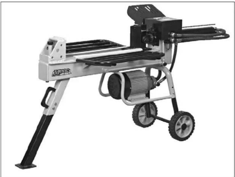
Operating Instructions for Electric Hydraulic Log Splitter
380-040
natural_image
Industrial robotic device with mounted gears and wheels, no visible text or symbolsSV Bruksanvisning i original
NO Bruksanvisning i original
EN Operating instructions in original
SVENSKA 4
SÄKERHETSANVISNINGAR 4
Klistermärken 4
Symboler 5
TEKNISKA DATA 6
Montering....7
Handhavande 8
SAFETY INSTRUCTIONS....31
Stickers 31
Symbols 32
TECHNICAL DATA....33
Assembly 34
Use 35
Wiring diagram.... 35
Hydraulic circuit diagram 36
Preparation 36
Use....37
Transport....38
Maintenance 38
Storage 39
SÄKERHETSANVISNINGAR
natural_image
Technical line drawing of a mechanical assembly with pipes and supports (no text or symbols)natural_image
Technical line drawing of a mechanical assembly with wheels and shafts (no text or symbols)natural_image
Technical line drawing of a mechanical device with rotating components and directional arrows (no text or symbols)natural_image
Mechanical diagram showing a rotating device with pulleys and a housing, no text or symbols presentnatural_image
Technical line drawing of a mechanical device with a lever and fan (no text or symbols)OBS!
natural_image
Technical line drawing of a mechanical device with labeled parts (no text or symbols present)Varselklistremerker
Symboler

natural_image
Technical line drawing of a mechanical assembly with no visible text or symbolsnatural_image
Technical line drawing of a mechanical assembly with wheels and shafts (no text or symbols)natural_image
Technical line drawing of a mechanical device with rotating components and directional arrows (no text or symbols)natural_image
Mechanical diagram showing a rotating device mounted on a base with pulleys and a dial (no text or symbols)natural_image
Technical line drawing of a mechanical device with a lever and adjustment knob (no text or symbols)OBS!
A. Strømledning
B. Strømbryter
C. Splint
D. Motorleder
E. Overopphetingsvern
F. Primærvikling
G. Sekundærvikling
H. Kondensator
natural_image
Technical line drawing of a mechanical device with a rotating knob (no text or symbols)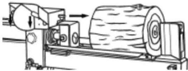
natural_image
Technical line drawing of a mechanical machine with a cylindrical component and directional arrow (no text or symbols)OBS!
natural_image
Technical line drawing of a mechanical device with labeled parts (no text or symbols present)natural_image
Technical line drawing of a mechanical assembly with pipes and supports (no text or symbols)natural_image
Technical line drawing of a mechanical assembly with wheels and shafts (no text or symbols)natural_image
Technical line drawing of a mechanical device with rollers and rotating components (no text or symbols)natural_image
Mechanical diagram showing a rotating device with pulleys and a housing, no text or symbols presentnatural_image
Technical line drawing of a mechanical device with a lever and adjustment knob (no text or symbols)UWAGA!
natural_image
Technical line drawing of a mechanical device with no visible text or symbols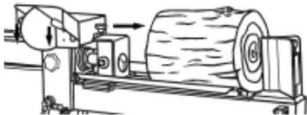
natural_image
Technical line drawing of a mechanical machine with a cylindrical component being processed (no text or symbols)UWAGA!
natural_image
Technical line drawing of a mechanical device with labeled parts (no readable text or symbols)Read the Operating Instructions carefully before use.
NOTE: The machine is only intended for splitting logs for home use. Do not use the machine for any other purpose than the one it is intended to be used for.
DANGER! The machine must only be used in accordance with these instructions. Read all warnings, safety instructions and other directives. Failure to follow all the instructions and safety instructions could result in the risk of material damage, serious personal injury and/or death. Read these instructions carefully before use. The manufacturer cannot accept liability for personal injury or material damage resulting from improper use.
Stickers
Locate the type plate on the machine. Read all the instructions and warning labels on the machine before using it.
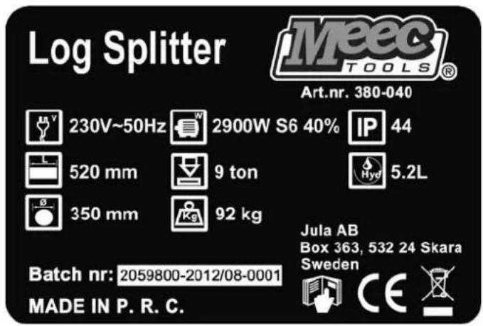
Type plate
NOTE: S6, duty factor 40%, with cycle time of 10 minutes corresponds to 6 minutes working and 4 minutes idling.
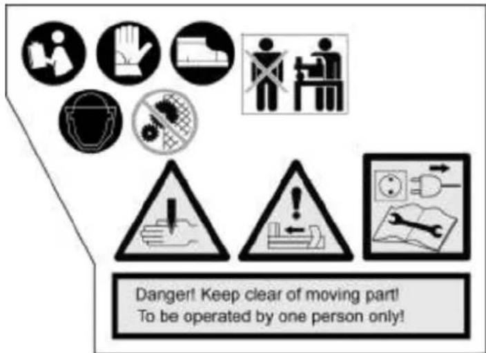
Warning stickers
Symbols

Read the instructions carefully before assembly, use and/or maintenance.

WARNING: The hydraulic oil is filed, please check oil level before using.

Wear safety gloves.
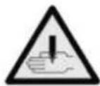
IMPORTANT: Risk of crush injury.
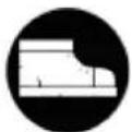
Wear safety shoes.

WARNING: Moving parts. Never allow any part of your body to come between the wood and piston when the machine is working.

Wear safety glasses or a face mask.
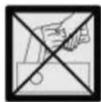
Never attempt to remove wood that has got stuck, or clear the blade with your bare hands.

Do not touch moving parts.
Always switch off the machine and unplug the power cord before cleaning or maintenance. Follow the maintenance instructions.
The machine must only be used by one person at once. Keep onlookers at a safe distance.
TECHNICAL DATA
| Electrical data | ||
| Voltage 230 VAC ± 10% | ||
| Frequency 50 ± 1 Hz | ||
| HVF | < | 0,02 |
| Power consumption 2900 W | ||
| Output | 2200 | W |
| Rated current 12 A | ||
| Motor speed 2800 rpm | ||
| Tripping temperature for overheating protection | 130°C | |
| Protection rating IP44 | ||
| Duty cycle S6/40% | ||
| Cross sectional conductor area, power cord | 1.5 mm ^2 | |
| Dimensions (L x W x H) 111 x 33 x 51 cm | ||
| Net weight 90 kg | ||
| Minimum fluid volume 5.2 l | ||
| Max. splitting force 88 kN | ||
| Max. log length 520 mm | ||
| Max. log diameter | 400 mm | |
| Min. log diameter | 50 mm | |
| Hydraulic pressure in machine | 24 MPa | |
| Inner diameter, cylinder | 63 mm | |
| Feed time | 10 s | |
| Return time | 8 s | |
| Noise level | ≤ 70 dB(A) | |
| Vibration, control handle | ≤ 2.5 m/s ^2 | |
| Environmental requirements | ||
| Use | ||
| Height above sea level | ≤ 1000 m | |
| Temperature 5 to 40°C | ||
| Relative humidity | 40°C < 50 % | |
| 20°C < 90 % | ||
| Temperature, transport and storage | -25 to 50°C | |
ASSEMBLY
- Open and unpack the packaging.
- Remove all loose parts from the packaging (instructions, accessories etc.).
- Remove the foam plastic.
- Two persons are required to assemble the machine.
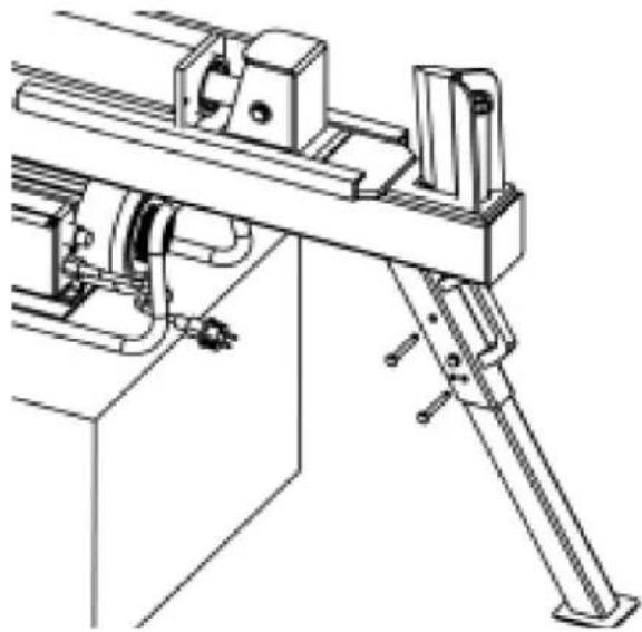
- Place the machine on a level, stable surface and fit the support leg.
natural_image
Technical line drawing of a mechanical assembly with pipes and supports (no text or symbols)- One person supports the machine, while the other does the fitting.
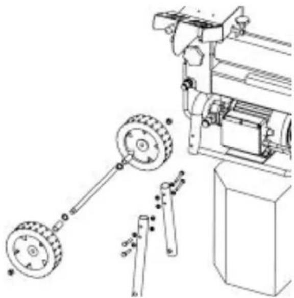
- Screw on the two wheel supports and fit the wheel axle. Fit the wheels (fig. 2).
- Lift down the machine. Two persons are needed to move the machine.
natural_image
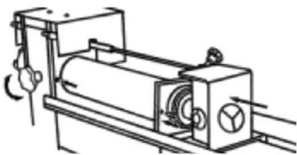
Technical line drawing of a mechanical assembly with wheels and shafts (no text or symbols)- Fit the cylinder.
- Remove the straps holding the hydraulic hoses.
- Undo the locking screw and press back the cylinder.
- Fit the two cap screws.
- Retighten the locking screw.
natural_image
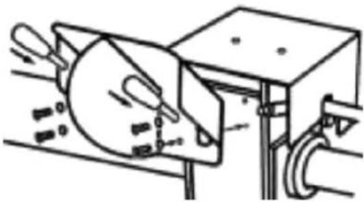
Technical line drawing of a mechanical device with rotating components and directional arrows (no text or symbols)- Fit the guard over the control handle.
natural_image
Mechanical diagram showing a rotating device mounted on a base with pipes and a circular component (no text or symbols)-
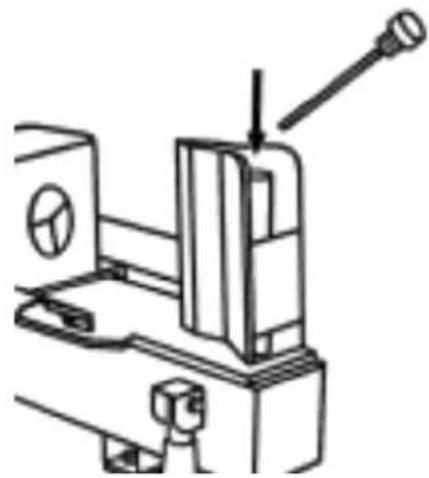
Check the level in the hydraulic fluid tank.
-
Remove the dipstick.
-
Top up with hydraulic fluid if necessary to that the level lies between the min and max markings on the dipstick.
-
Replace and tighten the dipstick.
-
Run the piston all the way out and back a few times to vent the tank.
natural_image
Technical line drawing of a mechanical device with a lever and adjustment knob (no text or symbols)NOTE:
- The packaging must be recycled in accordance with local regulations.
- Contact your dealer immediately if you discover any transport damage during the unpacking. Do not use the machine if it is damaged.
- Read all the instructions and safety instructions and all the warning labels on the machine prior to assembly and use.
- Save these instructions for future reference.
- Switch off the machine and unplug the power cord before cleaning.
USE
Wiring diagram
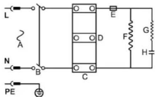
A. Power cord
B. Power switch
C. Terminal block
D. Motor wire
E. Overheating protection
F. Main winding
G. Auxiliary winding
H. Capacitor
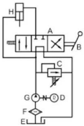
Hydraulic circuit diagram
flowchart
graph TD
    H["Hydraulic Valve"] --> A["Actuator"]
    A --> B["Directional Valve"]
    B --> C["Pressure Relief Valve"]
    C --> D["Directional Control Valve"]
    D --> E["Flowmeter"]
    E --> F["Directional Check Valve"]
    F --> G["Ground"]
    G --> H
    A --> X["Valve Symbol"]
    X --> B
    style A fill:#f9f,stroke:#333
    style B fill:#ccf,stroke:#333
    style C fill:#cfc,stroke:#333
    style D fill:#fcc,stroke:#333
    style E fill:#cff,stroke:#333
A. Hydraulic valve
B. Control handle
C. Relief valve
D. Electric motor
E. Hydraulic tank
F. Hydraulic fluid filter
G. Hydraulic pump
H. Hydraulic cylinder
Preparation
- Place the machine on a level, stable surface and anchor it.
- Wedge the wheels so that the machine cannot move when in use.
- Apply oil on the blade and top of the tank to simplify the work.
- Make sure that all the screw connections and hydraulic connections are properly tightened to keep the machine in safe condition.
- Check that the mains voltage corresponds to the rated voltage on the type plate.
- The machine should be connected to the mains supply with a residual current device with a maximum tripping current of 30 mA and with protection for overvoltage and undervoltage.
- Always check before using that the power cord, plug and power switch are undamaged. Do not use the machine if the power cord, plug, power switch or any other parts are damaged – risk of short circuiting and/or electric shock.
- Always check that all the safety devices are correctly fitted and in working order before use.
- Always wear suitable clothing, safety gloves, approved safety glasses and non-slip shoes. Do not wear loose-fitting clothing or jewellery.
- Cut the logs at right angles to a suitable length. Never attempt to split uneven, knotty or bent logs.
NOTE:
- Switch off the machine and unplug the power cord before adjusting.
- Always check that Allan keys/spanners etc. have been removed from the machine before switching it on.
- If using an extension cord, the conductor cross section must be dimensioned for the power supply to the motor. An extension cord must not be longer than 7.5 m. The maximum permitted cross sectional area is 2 mm ^2 .
- Do not use the machine in the vicinity of flammable liquids or gases.
- The hydraulic fluid is flammable and can explode. Always keep a fire extinguisher handy when working near flammable substances.
• Always check the level of the hydraulic fluid before using. Never run the machine with a low level of hydraulic fluid, this could damage the machine. - Keep the handles clean, dry and free from oil and grease.
- Always check before using that all the screw connections and hydraulic connections are correctly tightened, and that all the safety devices are correctly fitted and working.
- Place the machine in a suitable working area, free from obstacles.
- Clear away wood and splinters etc. regularly, to keep the working area free.
- Always check before using the machine that it is working properly by pressing down the control handle without any wood in the machine, and checking that it moves correctly.
Use
-
Let the motor idle for a few minutes and then switch off the machine. Allow the machine to cool for about 15 minutes before switching it on again to start working.
-
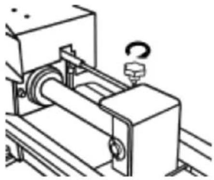
Adjust to the required log length by releasing the locking screw and running the piston to the required position, and then tightening the locking screw.
-
Place the logs on top of the tank, between the guides. Keep both control handles pressed down until the log has been split (fig. 7).
-
The piston will stop if you release one of the control handles.
-
The piston will go back when you release both control handles.
-
Switch off the machine and unplug the power cord after use.
natural_image
Technical line drawing of a mechanical device with a rotating knob (no text or symbols)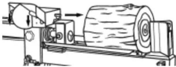
natural_image
Technical line drawing of a mechanical machine with a cylindrical component and directional arrow (no text or symbols)NOTE:
- Switch off the machine and unplug the power cord after use.
- Place the machine at least 3 metres from the mains outlet, to protect the outlet from dust. - Never allow children, or persons who have not read and understood these instructions, to use the machine.
- Familiarise yourself with the controls on the machine and how to use them.. Learn how to stop the machine quickly in an emergency.
• Never use the machine when you are tired or under the influence of drugs, alcohol or medication.
- The machine must only be used by one person at once. Keep onlookers, especially children, and pets at a safe distance.
- Never attempt to press the power switch or control handles with an object, or with any part of the body apart from your hands, and never attempt to bind or force down the control handles – risk of serious personal injury and/or death.
- Never allow any parts of the body to come between the blade and piston.
- Do not lean over, or try to step over the machine when it is switched on.
- Only split logs parallel to the direction of the grain. Some types of wood can burst and/or be ejected when splitting across the direction of the grain – risk of personal injury.
- Release the control handles if the machine cannot split the log. Release both handles to run back the piston. If the control handles are kept pressed down after the piston has stopped, the piston will not go back when you release the handles. In which case, switch off the motor and then switch it on again to continue.
- Release the control handles immediately, switch off the machine and unplug the power cord if the log fastens in the blade. Tap the log loose with a hammer. Do not use your hands.
- Never attempt to split more than one log at once, unless the piston has fully gone out and you need to use another log to completely split the first one. Never try to split several logs on top of each other.
• Clear away the split logs regularly, to keep the working area free.
• Regularly check that all the screw and hydraulic connections are correctly tightened.
- Never use the machine on slippery or unsafe surfaces – risk of personal injury.
- Never leave the machine unattended when switched on.
- Do not expose the machine to rain or moisture – risk of electric shock.
• Make sure the work area is well lit.
- Never modify the motor speed. The maximum motor speed is set at the factory to comply with the applicable safety regulations.
- Switch off the machine immediately and unplug the power cord in the event of a fault or abnormal function. If the noise level increases or the piston moves unevenly, this could mean that the hydraulic fluid level is too low. Check and top up if necessary.
- Do not pull the power cord to unplug the plug.
Transport
- Use the transport handle for short distances.
- Remove the wheels and support leg to transport longer distances.
NOTE:
- Never lift or carry the machine when the motor is running.
- Be careful when moving the machine on uneven or unstable surfaces.
- Make sure that the machine does not tilt, tip over or drop down.
- Never allow anyone to ride on the machine when moving it.
MAINTENANCE
NOTE:
- Switch off the machine, unplug the power cord and wait until all moving parts have stopped completely before carrying out any maintenance or repairs.
• The hydraulic system is adjusted at the factory. Never adjust the valve. - Never modify the machine in any way. Modifications to the machine mean that it is not being used properly, and could lead to serious personal injury.
- Only use spare parts recommended by the manufacturer.
- Oil in the machine with a cloth lightly moistened with oil to protect it from corrosion. File the blade if it is blunt, or chipped. Wear safety gloves.
- Never use your hands or other parts of the body to look for leaks in the hydraulic system. Fluid issuing from the machine at high pressure can cause toxic substances to be injected into the body and cause serious personal injury and/or death. Check for suspected leaks by moving a piece of paper over the area to see if it becomes discoloured.
• Never undo hydraulic connections or the cap on the hydraulic tank when the machine is running. - If the motor is unduly overloaded this will trigger the overheating protection, which switches off the motor. Switch off the machine, unplug the power cord and allow to cool for 30 minutes until the overheating protection is reset. Contact your dealer if the machine does not work properly after it has cooled.
- Other problems with the hydraulic system and/or motor than those described above must only be checked by qualified personnel.
- Check the level of the hydraulic fluid regularly. If the piston moves slowly or unevenly, this could mean the hydraulic fluid is at a low level, or that there is air in the tank. If so, follow the instructions below.
- Check the condition of the hydraulic fluid at the end of every season, and change when necessary. The machine has a hydraulic fluid filter, so that normally the hydraulic fluid only needs changing if the noise level on the machine increases or the piston moves unevenly. Follow the instructions below.
-
Changing the hydraulic fluid, and bleeding:
-
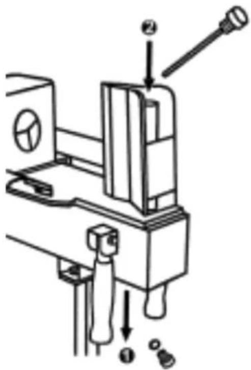
Lift and block up the wheels about 5 cm over the ground. Place a suitable container under the drain plug.
- Unscrew the drain plug in the front of the tank and allow the hydraulic fluid to run out into the container.
- Replace the drain plug and tighten.
- Fill up with hydraulic fluid to the level between the Min and Max markings on the dipstick.
- Run the piston all the way out and back a few times to vent the tank.
- Check the level of the hydraulic fluid again, and top up if necessary. Replace and tighten the dipstick.
natural_image
Technical line drawing of a mechanical device with labeled parts (no readable text or symbols)NOTE: On delivery the machine is filled with 32 W AW hydraulic fuel. Only use this type of hydraulic fluid, or an equivalent grade. Do not mix different types of hydraulic fluid. Only use pure fluid. Make sure that no impurities penetrate into the hydraulic system.
Storage
NOTE:
- Switch off the machine and unplug the power cord before putting it away.
- Allow the machine to cool for at least 5 minutes before putting it away.
- Keep the power cord away from heat, oil and sharp edges.
- Store the machine in a clean, dry place. Do not store the machine outdoors, or in damp or corrosive environments.
- Store the machine out of the reach of children.
Jula reserves the right to make changes. In the event of problems, please contact our service department. www.jula.com
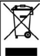
Care for the environment!
Must not be discarded with household waste! This product contains electrical or electronic components that should be recycled. Leave the product for recycling at the designated station e.g. the local authority's recycling station.
- Operating Instructions for Electric Hydraulic Log Splitter
- SVENSKA 4
- SÄKERHETSANVISNINGAR 4
- TEKNISKA DATA 6
- Montering....7
- Handhavande 8
- SAFETY INSTRUCTIONS....31
- TECHNICAL DATA....33
- Assembly 34
- Use 35
- SÄKERHETSANVISNINGAR
- OBS!
- Symboler
- UWAGA!
- Read the Operating Instructions carefully before use.
- Stickers
- Symbols
- ASSEMBLY
- NOTE:
- USE
- Wiring diagram
- Hydraulic circuit diagram
- Preparation
- Transport
- MAINTENANCE
- Storage
- Care for the environment!
Brand : Meec Tools
Model : 380-040
Category : Log splitter