
Seagull - Range hood ELICA - Free user manual and instructions
Find the device manual for free Seagull ELICA in PDF.

| Brand | Elica |
| Model | Seagull |
| Product Type | Built-in range hood with rim extraction |
| Weight | Approx. 65 kg (143 lbs) |
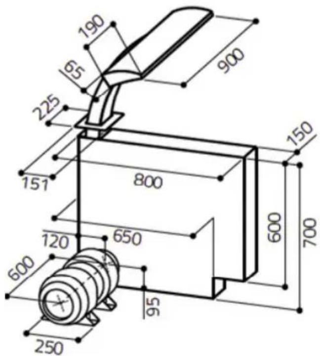
| Dimensions (Cut-out) | Refer to installation diagram (fig. e in manual) |
| Power Supply | 220-240 V, 50/60 Hz (typical; check type plate) |
| Motor Power | Fan motor with adjustable speeds (3 settings) |
| Lighting | Integrated LED lights (replaceable only by service) |
| Filter Type | Metal grease filter, magnetically held, dishwasher safe |
| Filter Cleaning Interval | Every 2 weeks |
| Control Panel | Touch controls on side arm: T1 (extend/retract), T2 (fan speed), T3 (light) |
| Fan Speeds | 3 speeds (plus off); speed-dependent LED colors |
| Extension Type | Motorized vertical extension from worktop |
| Ducting | Exhaust air mode; requires duct connection (pipe size not specified) |
| Safety Features | Automatic stop if obstruction detected; must operate with filter; negative pressure limit 4 Pa |
| Materials | Stainless steel body, aluminum/painted surfaces |
| Cleaning | Mild detergent, no abrasives; stainless steel cleaner recommended |
| Spare Parts | Genuine Elica parts required; LED only by service; filters replaceable |
| Installation | Requires 2 persons; weight-bearing side wall; certified electrician for electrical connection |
| Compliance | CE, WEEE directive 2002/96/EC |
| Warranty | Refer to service booklet (not specified in manual) |
Frequently Asked Questions - Seagull ELICA
User questions about Seagull ELICA
0 question about this device. Answer the ones you know or ask your own.
Ask a new question about this device
Download the instructions for your Range hood in PDF format for free! Find your manual Seagull - ELICA and take your electronic device back in hand. On this page are published all the documents necessary for the use of your device. Seagull by ELICA.
USER MANUAL Seagull ELICA
natural_image
Modern desk lamp with four circular cutouts on a white base, no visible text or symbols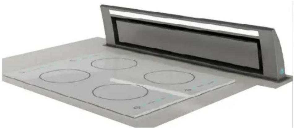
natural_image
Exterior view of a modern office building (no signage)Seagull
de
Installation
natural_image
Technical line drawing of a mechanical assembly with components and a directional arrow indicating motion (no text or symbols)Abb. c
natural_image
Interior view of a beige industrial cabinet or enclosure with a black rectangular frame on the floor (no text or symbols visible)Abb. d Abb. e
natural_image
Simple diagram with four red shapes on a brown wooden surface, one rectangle and one circle, with dimension labels 155 and 115 (no text or symbols beyond measurement indicators)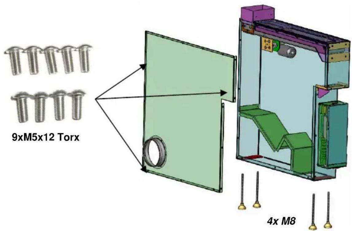
Abb. f
Installation
natural_image
Interior view of an open industrial enclosure with visible structural components and wiring (no text or symbols)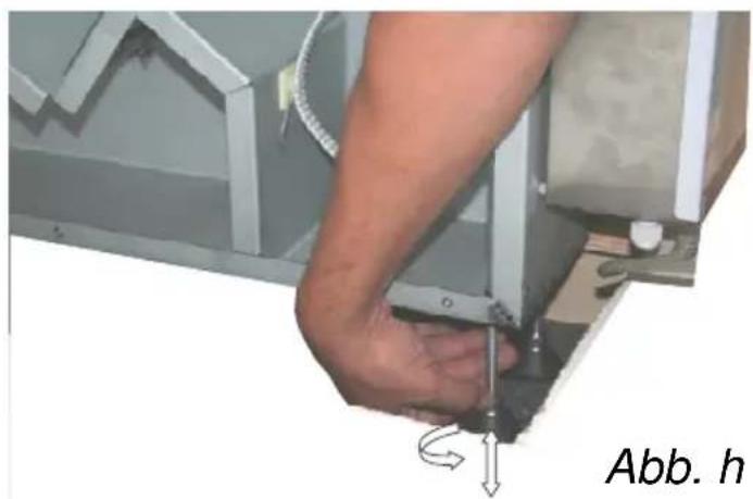
natural_image
Close-up of a hand using a tool to adjust or install a mechanical component, with no visible text or symbols.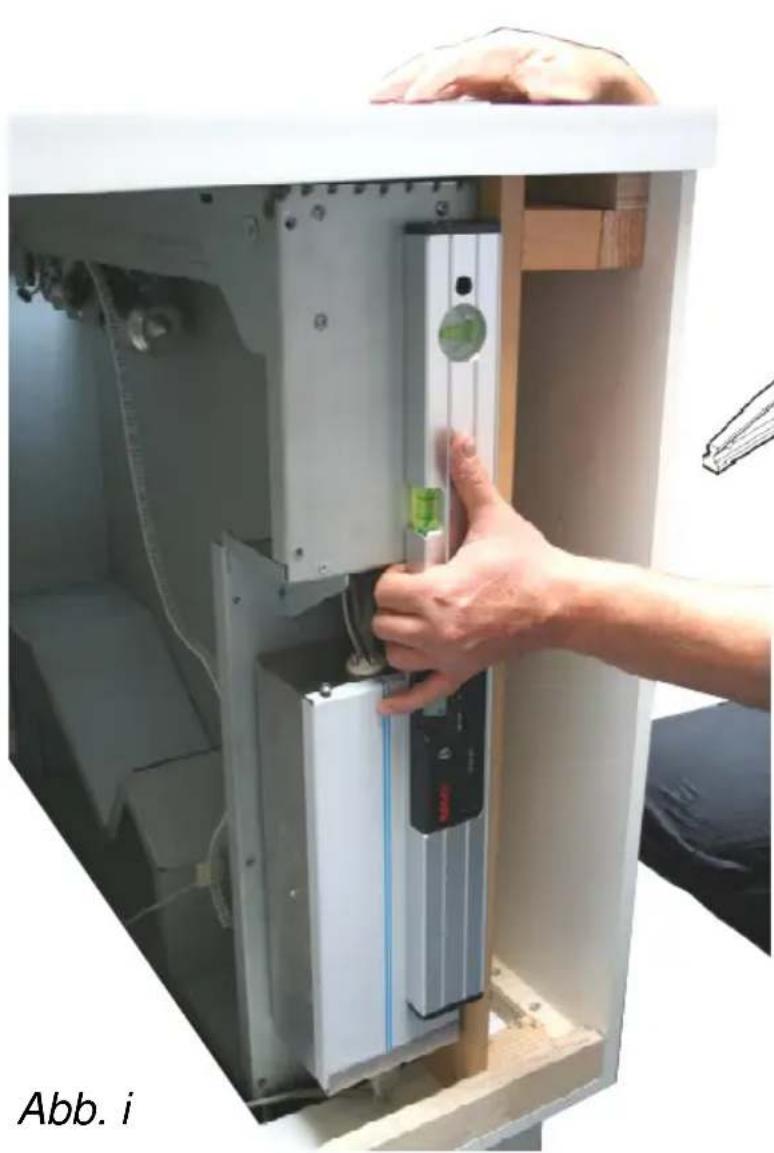
natural_image
Person installing or adjusting a device inside a technical enclosure, no visible text or symbols on the device itself.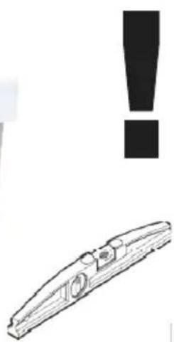
natural_image
Simple line drawing of a mechanical component with an exclamation mark above it (no text or symbols on the component itself)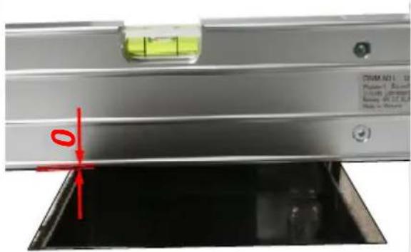
Abb. j
Installation
natural_image
3D illustration of a wooden plank with red circular features and a purple trough, alongside a magnet and a blue ring (no text or symbols)Installation
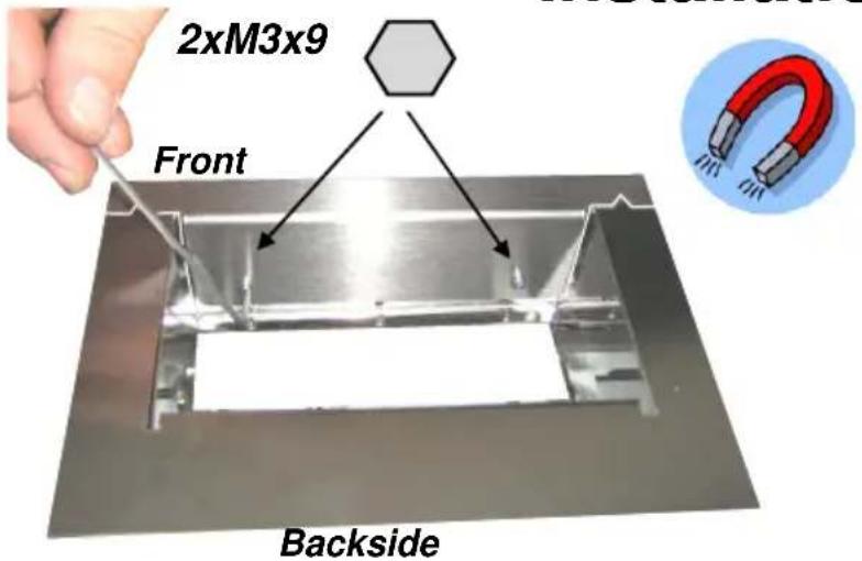
Abb. m
flowchart
graph TD
    A["Installation"] --> B["M6x16"]
    B --> C["Assembly"]
    C --> D["Toolset with Tool Icon"]
    D --> E["Assembly"]
    E --> F["Toolset with Tool Icon"]
    F --> G["Assembly"]
Abb. p
Installation
natural_image
Close-up of a hand adjusting cable and connector components on a metal panel (no text or symbols visible)Abb. r
de
Installation
Sicherheitshinweise
natural_image
Illustration of a roof-mounted device with a yellow arrow indicating clockwise rotation and a warning symbol (no text or labels)Bedienungsanleitung
natural_image
Illustration of a modular kitchen appliance with open lid, front panel, and control panel (no text or symbols)del ventilatore.
elica to help you enjoy life
Dear customer,
Thank you for choosing a elica extractor hood.
Please carefully read the following information and explanations on the proper use of your new elica hood before using the appliance for the first time. Please also read our operating and installation instructions as well as the cleaning recommendations to ensure that you enjoy many years of service from your appliance.
Safety information
These operating and installation instructions contain important information that must be observed to ensure safe and reliable operation of the extractor hood. Please store them in a safe place for future reference. These operating instructions refer to several versions of the appliance. They may contain descriptions of certain features not found on your model.
The extractor hood must not be used by persons (incl. children) with impaired physical or mental capabilities or persons who lack experience and/or knowledge of how to use it. Children must be supervised to ensure that they do not play with the appliance.
Intended use
The extractor hood may only be used to extract kitchen vapours above the cooking appliances in private households. Any other use will be deemed to be improper. Improper use of the hood may pose a danger to persons and objects. The extractor hood must not be used as a shelf to store objects such as bottles, spice jars or other loose objects.
Installation
The appliance may only be installed and connected by an authorised technician observing all relevant regulations of the electric utility companies and the applicable building regulations. During installation, observe the relevant instructions! Damaged appliances may not be put into operation. Defective parts must be replaced with genuine parts. Repairs should only be carried out by authorised technical staff.
Danger of intoxication!
If the extractor hood is operated in extraction mode at the same time as other room-air-dependent fire appliances (e.g. wood, gas, oil or coal-fired appliances) in the same room, lethal combustion gases may be directed back into the room due to the resulting negative pressure. For this reason, you must ensure a sufficient air supply at all times! The negative pressure in the room must not exceed 4 Pa (0.04mbar).
Fire hazard!
The extractor hood must never be operated without the grease filter and must always be used under supervision. Filters that are saturated with grease can pose a fire hazard! Keep the extractor hood under constant supervision when deep-frying! Remember to clean out the filters regularly. Flam-béing under the extractor hood is not allowed! Gas appliances may only be used under the extractor hood with saucepans placed over them! If you are using more than three gas rings at the same time, operate the extractor hood at power level "2" or higher. This prevents the build-up of heat in the appliance.
Preparing for use
The extractor hood model complies with the relevant safety regulations for kitchen appliances in private households. The requirements regarding the installation location are described in the user documentation supplied with the appliance. If you have any doubts as to whether your intended installation location meets the requirements, please contact our service department. Damaged appliances may not be put into operation. Defective parts must be replaced with genuine spare parts or parts specified by elica. Repairs should only be carried out by authorised technical staff.
Activated carbon filter
For activated carbon filters fitted in GUTMANN extractor hoods (C Version), please read the separate operating instructions provided!
Transport, unpacking, installation
Condensation may occur if the appliance is brought into the installation site
from a cold environment. Please wait until the appliance has adjusted to the temperature and is completely dry before operating it. The acclimatization period depends on the temperature difference and the type and design of the appliance. However, it should be at least 12 hours.
Connecting the power supply
Check that the rated voltage indicated on the appliance matches the mains voltage in your area. Connection to the incorrect voltage will damage or destroy the appliance.
Before switching on the appliance, check that all cables and lines are properly fitted and undamaged. Make sure in particular that there are no kinks in the cables, that they are not pulled too tightly around corners and that no objects are resting on them. Also make sure that all plug connections are securely inserted. Faulty shielding or wiring poses a health hazard (electric shock) and can destroy other appliances. Appliances with mains plugs are fitted with a safety-tested mains cable for the respective country of use and may only be connected to a correctly earthed safety socket. Otherwise, there is a risk of electric shock. Make sure that the socket on the appliance or the domestic safety socket is easily accessible so that the mains cable can be unplugged from the socket in an emergency or during servicing and maintenance work.
Danger of electric shock!
Do not clean the hood with a steam cleaner or water pressure cleaner. The hood must be disconnected from the power supply prior to cleaning
Safety information
Installation, connection, commissioning and repair work may only be carried out by authorised technicians. This technician will be able to determine suitable methods for securing the extractor hood and providing the necessary exhaust air ducting. The choice of attachment must take account of the weight of the extractor hood and the load exerted on the supporting surface. Note the extraction values of the dowels supplied. Depending on the supporting surface, these have the following values: Dowel ∅10 mm: concrete B25 9.4 kN brick Z20 5.2 KN solid calcium silicate KSV20 4.8 KN. In the case of unstable supporting surfaces, a construction specialist such as a structural engineer or architect must be consulted to ensure the extractor hood is safely installed.
Danger of injury!
The hood body may contain sharp edges resulting from the manufacturing process. For this reason, safety gloves must be worn when installing it.
Safety information – Please observe when extending/retracting the hood
Please make sure that there are no objects near (approx. 5 cm) the cover plate / hood when extending/retracting it. Any objects that drop into the hood shaft can damage the hood!
Danger of electric shock
The mains voltage must correspond to the details indicated on the type plate. This plate is located inside the hood near the filters. Only connect the extractor hood to a properly installed safety
Installation instructions
en
socket. This socket must be easily accessible after the installation so that the extractor hood can be disconnected from the power supply if necessary. If a fixed connection is used (e.g. if a suitable wall socket is not available), the extractor hood may only be connected by a qualified electrician. For fixed connections, the extractor hood must be connected to a single power circuit fitted with an isolating device. Isolating devices include switches with a contact gap of at least 3 mm and all-pole switches, e.g. circuit breakers and contactors. Before working on the electrical connection of the extractor hood commences, the mains circuit/circuits must be switched off. Before drilling the mounting holes, make sure that no electrical cables can be damaged during drilling. The electrical connection must be prepared in such a way as to allow the easy connection of the extractor hood. Local regulations must be observed.
Exhaust air ducting (for extraction mode)
Exhaust kitchen air must not be ducted into a chimney flue that is also used for the exhaust air from devices using fuels (e.g. gas). Official regulations regarding ducting of exhaust air must be observed. The exhaust air path must be prepared in such as way as to allow the easy connection of the extractor hood. The exhaust air hose must not have any kinks. If the extractor hood is operated in extraction mode at the same time as other room-air-dependent fire appliances (e.g. wood, gas, oil or coal-fired appliances) in the same room, lethal combustion gases may be directed back into the room due to the resulting negative pressure. The operator must therefore provide a sufficient air supply at all times. The negative pressure in the room must not exceed 4 Pa (0.04mbar).
Solid fuel appliances
The installation of the extractor hood above solid fuel appliances, which can pose a fire hazard, (e.g. flying sparks) is only permissible if the solid fuel appliance is equipped with a sealed, non-removable cover.
We reserve the right to make technical changes.
en
Installation instructions
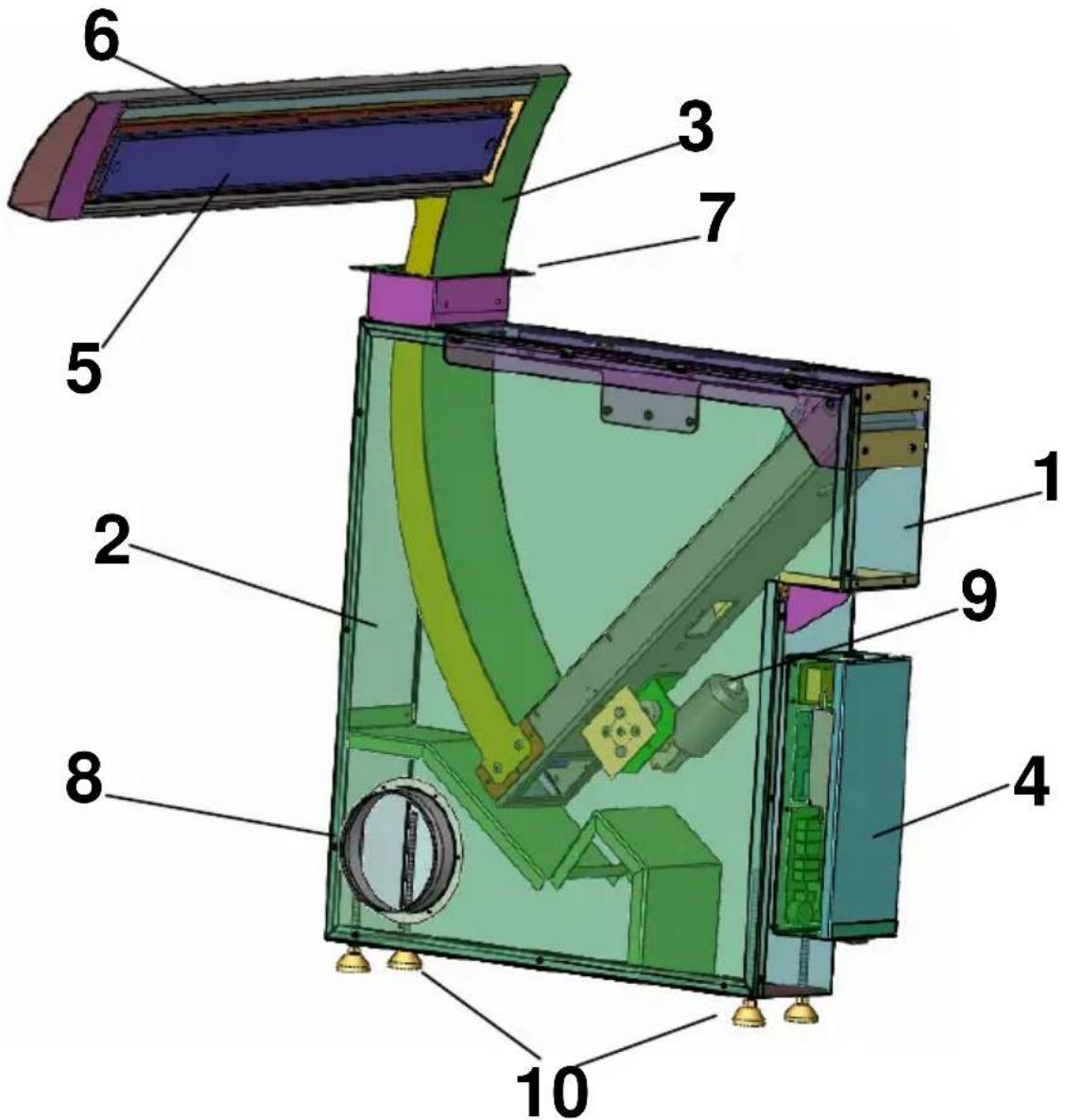
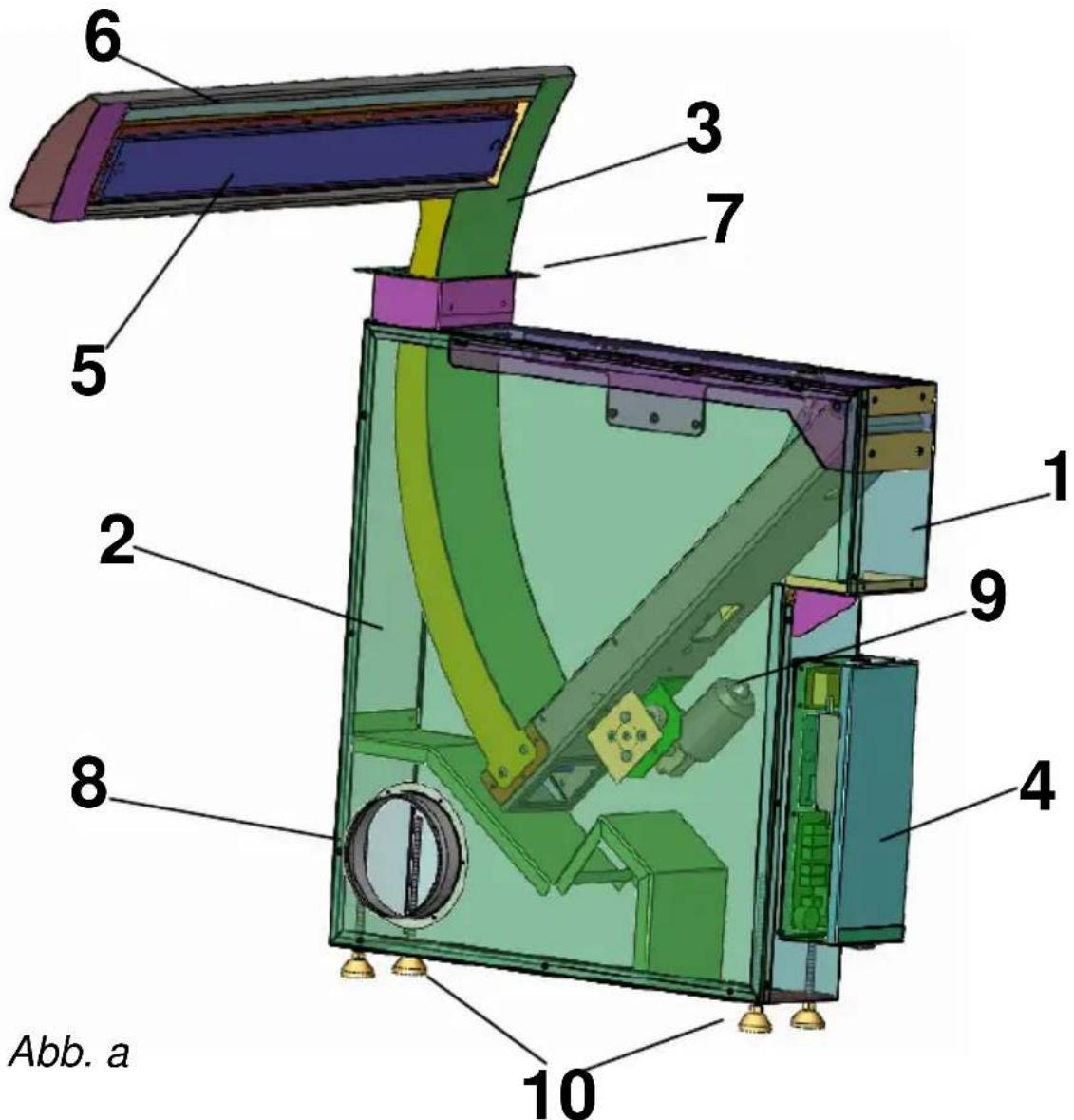
1: Hood base frame
2: Housing cover
3: Hood
4: Control unit
5: Stainless steel cover plate with the filters fit ted behind it
6: Lighting
7: Cover plate
8: Pipe connection
9: Drive motor
10: Adjustable feet
11: Fan motor
Installation instructions
General: All of our extractor hoods are extensively tested before they leave our facilities.
So as to make it easier to understand how the hood components fit together, the extractor hood is supplied in separate units that comprise the hood (3), hood base frame (1), cover plate (7) and the fan motors (11). These components have to be installed as detailed in the following. Installing these parts requires 2 specialists.
→ Make sure that there is a load bearing / suitable side wall (fig. d) inside the base cabinet that is going to bear the weight of the Seagull hood (\~65KG).
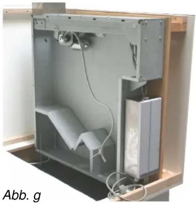
→ Lift the Seagull hood out of its packaging (with two people). Remove the housing cover (fig. C + f) from the hood's base frame. Screw the adjustable feet 10 to the bottom of the hood's base frame 1.
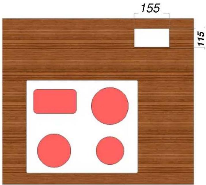
→ Cut out a section of the worktop to the specified dimensions (fig. e).
→ Insert the hood's base frame 1 into the base cabinet, align and, if necessary, adjust the feet 10 (fig. G, h, i). Make sure that the hood shaft is flush with the top edge of the worktop (fig. j).
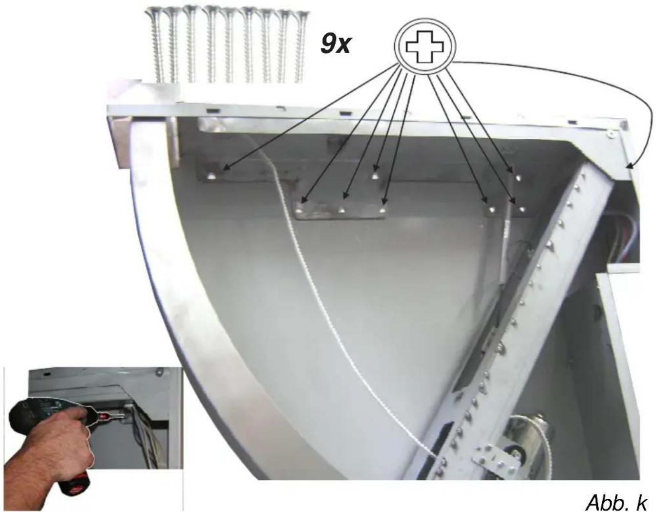
→ Screw the hood's base frame 1 to the intermediate cabinet side wall using the new fastening holes and the nine Spax screws (4.5x30). If necessary, check the angle again (fig. K).
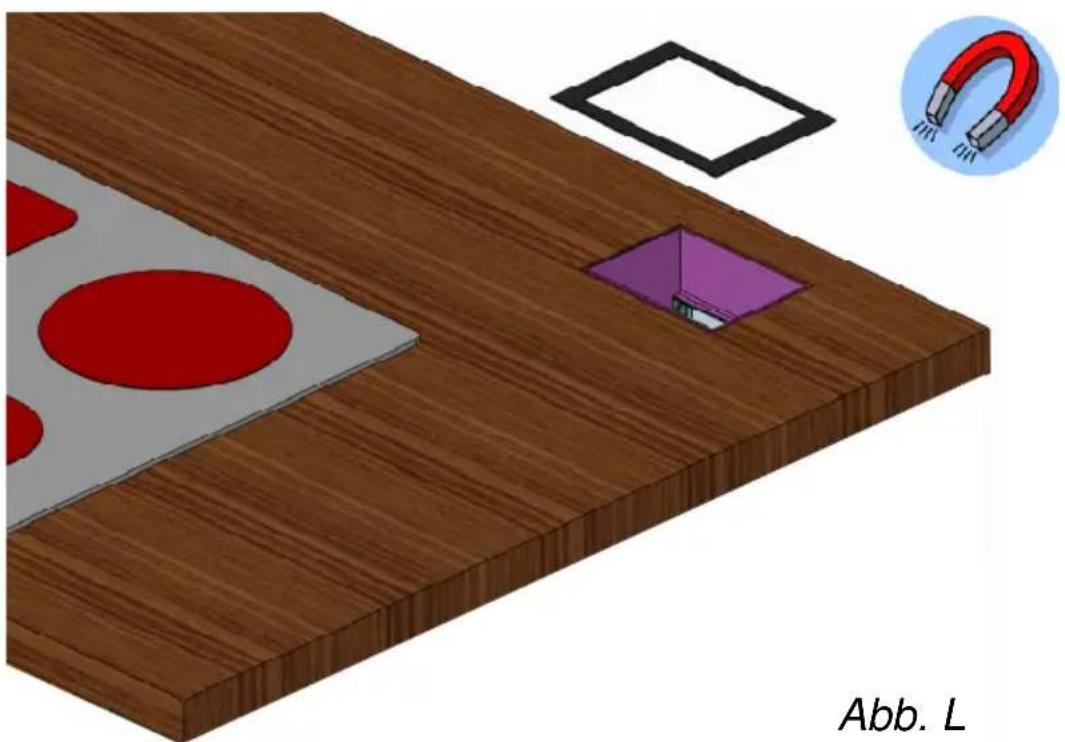
→ Clean the edges of the cut-out in the worktop (fig. L) (remove oil and grease) and then remove the adhesive foil from the magnetic strip and attach. Caution! Wide side = front side.
→ Insert the cover plate 7 (fig. L+m) into the cut-out in the worktop and fasten with two M3x9 screws.
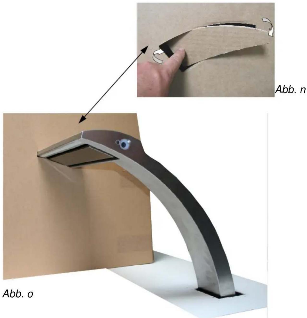
→ Take the assembling aid (box) and remove the pre-cut template. Place the assembling aid (fig. n) on top of the worktop and insert the hood (3) into the template.
Installation instructions
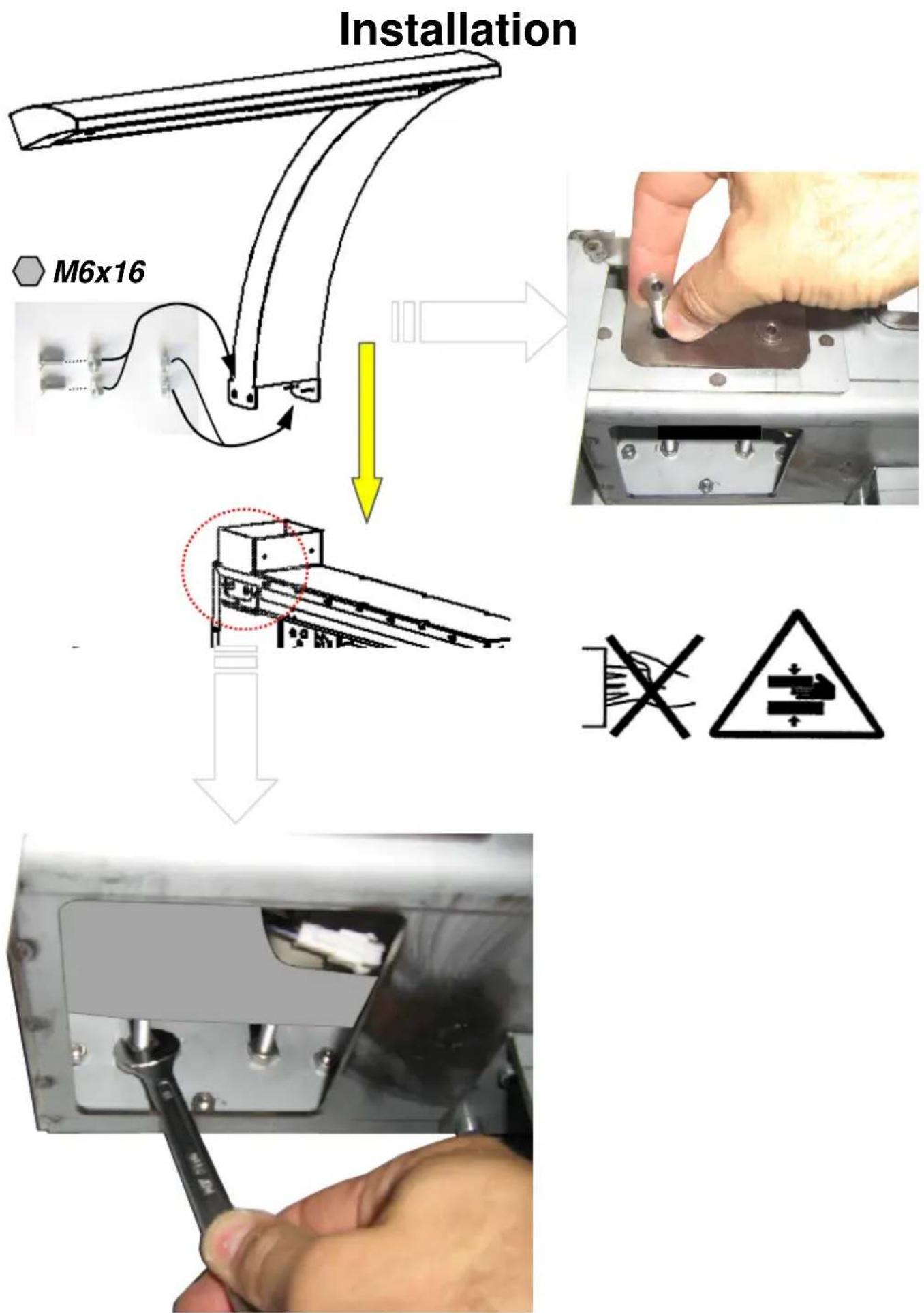
Now screw the hood's base frame 1 to the hood 3 with two M6x16 counter sunk screws and two M6 grub screws; if required, adjust hood (fig. P).
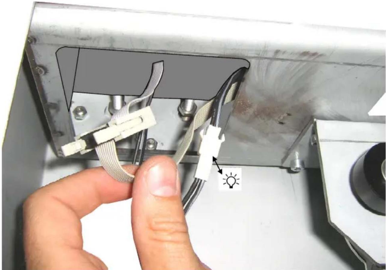
→ Connect the control cable (plug connection) and lighting cable (plug connection) to the power supply (fig. r). Make sure that the cables do not touch, rub against each other or get trapped when the hood is extended/retracted.
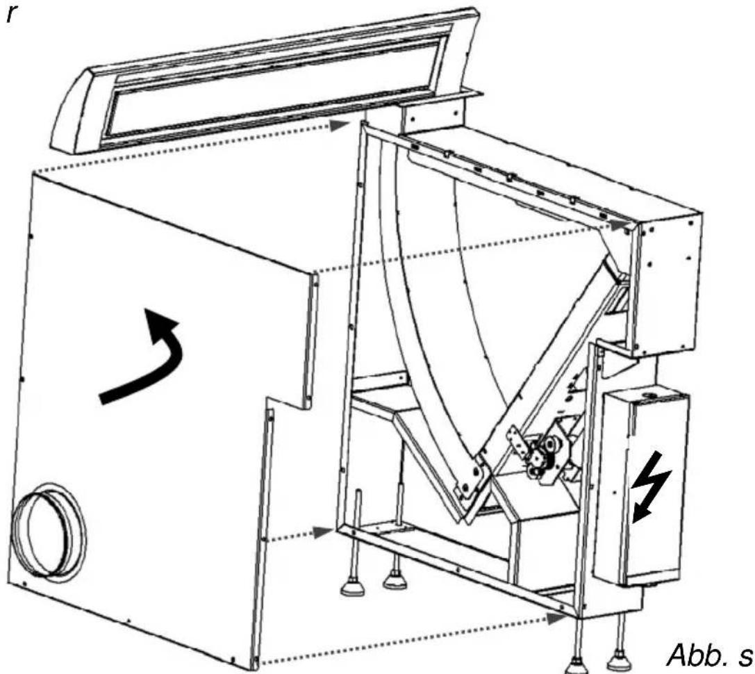
→ Screw the housing cover back onto the hood's base frame 1 fig. s.
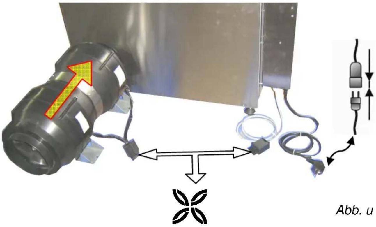
→ Connect the pipe connection 8, extraction hose and fan motor 11 using the supplied hose clips (fig. below).
→ Connect the fan motor cable 11 to the control 4 (plug connection (fig. below).
→ Plug the power cable into the socket and test the hood (please refer to the operating manual for information on testing the hood).
Operating Instructions
en
General method of operation
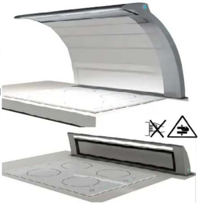
With its efficient all-round extraction, the innovative Seagull rim ventilator offers excellent extraction over the hob used. The hood's body extends from the worktop upwards and comes to rest right over the centre of the hob. The sophisticated design means that the actual hood body is very slim and hardly noticeable. The metal filters are fitted inside the hood body and concealed by a stainless steel plate. They are easy to replace and can be replaced without any tools. The hood body is moved up and down by a motor. The extraction capacity is controlled via the control panel which is fitted to the side of the hood's arm. For reasons of hygiene, the Seagull all-round extractor hood is made from stainless steel.
Product description
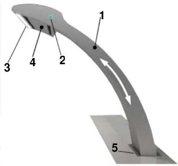
1 Hood body (extended)
2 Control panel
3 Lighting (LED)
4 Stainless steel plate with metal filters fitted behind it
5 Cover panel
Operating instructions
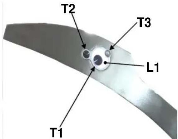
The extractor hood and fan motor's output can be controlled as follows at the control unit:
natural_image
Illustration of a curved metal panel with circular cutouts and a warning symbol (no text or labels)Operating the hood/fan motor from the operating panel
Extending – retracting the hood T1
To extend the hood press T1.
Pressing T1 again will make the hood retract.
Fan output T2
The fan output can be controlled by pressing T2.
When the hood is retracted:
Press T2 1x = Fan setting 1
L1 green LED illuminates.
Press T2 2x = Fan setting 2
L1 cyan LED illuminates.
Operating Instructions
Press T2 3x = Fan setting 3 L1 dark blue LED illuminates.
Press T2 4x = Fan off L1 white LED illuminates.
When the hood is retracted:
Press T2 1x = Fan setting 2 L1 cyan LED illuminates.
Press T2 2x = Fan setting 3 L1 dark blue LED illuminates.
Press T2 3x = Fan off L1 white LED illuminates.
If the hood stops moving because of resistance while being extended or retracted, the red LED L1 will come on. In this event, switch the hood's power off for 10 s.
Lighting T3
The lighting can be switched on by pressing T3.
Cleaning and care
Cleaning the surfaces
Danger due to electric shock! Disconnect the extractor hood from the power supply by pulling the plug out of the socket or by switching off the fuse. When cleaning, make sure that no water penetrates the device.
Regular cleaning of the surface saves laborious removal of stubborn contamination. Only use conventional detergents or universal cleaning agents suitable for cleaning stainless steel/aluminium. Never use abrasive cleaning agents or steel wool. After cleaning the hood, treat the stainless steel surfaces with a stainless steel care product.
Painted surfaces should only be cleaned using a mild detergent solution and a very soft cloth. Only use a soft damp cloth to clean the operating panel.
On hoods fitted with a panel below the filter (edge extraction), grease deposits occur at the edge of the panel. These deposits occur for physical reasons and are not due to a malfunction of the hood. Please clean the panel underneath the filter regularly to prevent the formation of stubborn residues.
Cleaning and care instructions
When cleaning the grease filters, also remove any grease deposits from the accessible housing components. This will prevent a fire hazard and maintain an optimum range of functions. Use hot soapy water or a mild window cleaning agent to clean the hood. Do not scratch off baked-on deposits. Soften them using a damp cloth. Do not use abrasive agents or scouring pads.
Note: Do not use alcohol (spirits) on plastic surfaces, as dull spots may result.
Caution: Ventilate the kitchen sufficiently, no open flame.
Only clean the operating panel with a soft damp cloth (mild detergent solution). Do not use stainless steel cleaners for the sliding switch/pressure switch.
Stainless steel surfaces:
Use a mild and non-abrasive stainless steel cleaning agent. Do not clean stainless steel surfaces with abrasive scouring pads or with cleaning agents containing sand, soda, acid or chloride! Clean in direction of polish only.
We recommend our stainless steel cleaner no. 461731. See the enclosed service booklet for the order address.
Aluminium, varnished and plastic surfaces:
Use a soft microfibre cloth. Do not use dry cloths. Use a mild window-cleaning agent. Do not use aggressive cleaning agents or agents containing acid or lye! Do not use scouring agents.
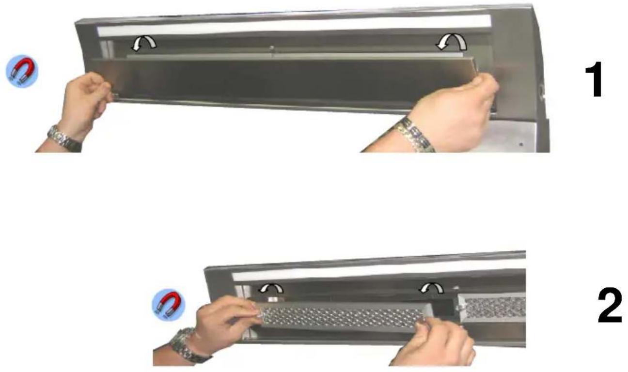
Exchange and cleaning of the filter
Fire risk! The performance of the extractor hood is affected by containing fat remains and therefore the fire risk increases. To prevent a fire risk please clean the metal filter regularly. The metal grease filter must be cleaned every 2 weeks at last.
At first press therefore the stainless steel pane with both hands upwards and then slowly down. The underlying metal grease filter is held by a magnet and can be simply flapped down.
The metal grease filter is to be cleaned at best in a dishwasher or in hot soapy water. Aggressive cleaners should not be used. The guarantee can't be applied if a discoloured on the filter is a result of using an aggressive dishwashing liquid. Please avoid temperatures over 55 degrees. Attention: do not use 3-phase-cleaners or clean the filter in a commercial dishwasher. The use of aggressive cleaners like fuel, acetone, trichlorethylene destroys the filter!
Reinstate the metal filter after the cleaning and close the stainless steel pane with both hands.
2
Lighting
Standard model with LED lighting! Changing of the LED lighting only possible by the service department!
Faults
Please contact our service department immediately, if:
- If the extractor hood creates unusual noises and you are unable to detect any faults after checking the extraction air line
- If you discover, for example, by hearing strange noises, that the motor is faulty or defective
- the switches are not working properly.
Please remember to indicate your extractor hood model and the corresponding serial number. This information can be found on the type plate. This plate is located inside the hood near the filters.
Disposal
Packaging
The packaging for the extractor hood is recyclable. Cardboard and polyethylene film (PE) are used as packaging materials. These materials must be disposed of in an environmentally compatible manner in accordance with local regulations.
Extractor hood
Your local authority will also be happy to advise you on the environmentally sound disposal of old household appliances.
Environmental information

All models manufactured by elica are identified in accordance with European Directive 2002/96/EC on waste electrical and electronic equipment (WEEE). This directive specifies the framework for the EU-wide return and disposal of used appliances. Please ask your dealer for information about current disposal methods.
We reserve the right to make technical changes.
en
elica
aria nuova
Via Dante n°288
60044 Fabriano (AN) Italia
C.F. Reg. Imp. AN 00096570429
Cap. Soc. Euro 12.664.560 i.v.
- Installation
- Sicherheitshinweise
- Bedienungsanleitung
- elica to help you enjoy life
- Safety information
- Intended use
- Danger of intoxication!
- Fire hazard!
- Preparing for use
- Activated carbon filter
- Transport, unpacking, installation
- Connecting the power supply
- Danger of electric shock!
- Danger of injury!
- Safety information – Please observe when extending/retracting the hood
- Danger of electric shock
- Installation instructions
- Exhaust air ducting (for extraction mode)
- Solid fuel appliances
- Operating Instructions
- General method of operation
- Product description
- Operating the hood/fan motor from the operating panel
- Fan output T2
- Lighting T3
- Cleaning and care
- Cleaning the surfaces
- Cleaning and care instructions
- Stainless steel surfaces:
- Aluminium, varnished and plastic surfaces:
- Exchange and cleaning of the filter
- Lighting
- Faults
- Disposal
- Packaging
- Extractor hood
- Environmental information
Brand : ELICA
Model : Seagull
Category : Range hood