LC-WB200 - Video projector EIKI - Free user manual and instructions
Find the device manual for free LC-WB200 EIKI in PDF.


User questions about LC-WB200 EIKI
0 question about this device. Answer the ones you know or ask your own.
Ask a new question about this device
Download the instructions for your Video projector in PDF format for free! Find your manual LC-WB200 - EIKI and take your electronic device back in hand. On this page are published all the documents necessary for the use of your device. LC-WB200 by EIKI.
USER MANUAL LC-WB200 EIKI
Refer to the Owner's Manuals below for details about network function.
☐ Network Set-up and Operation
PJ Network Manager
natural_image
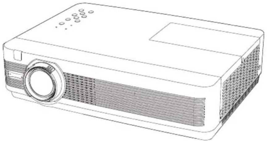
Line drawing of a projector with front panel and screen (no text or symbols)Owner's Manual
This Multimedia Projector is designed with the most advanced technology for portability, durability, and ease of use. This projector utilizes built-in multimedia features, a palette of 16.77 million colors, and matrix liquid crystal display (LCD) technology.
◆ Compact Design
This projector is designed compact in size and weight. It is easy to carry and installed anywhere you wish to use.
♦ Simple Computer System Setting
The projector has the Multi-scan system to conform to almost all computer output signals quickly (p.28). Up to WUXGA resolution can be accepted.
◆ Useful Functions for Presentations
- The digital zoom function allows you to focus on the crucial information during a presentation (p.35)
- The MIC function and 10W audio output allows you to make a presentation without any external audio equipment (p.24).
♦ Lamp control
Brightness of the projection lamp can be selected (pp.25, 54).
♦ Direct Off Function
With the Direct Off function, you can disconnect the power cord from the wall outlet or turn off the breaker even during projection (p.20).
♦ Logo Function
The Logo function allows you to customize the screen logo (pp.46-48). You can capture an image for the screen logo and use it for the starting-up display or between presentations.
◆ Picture in Picture Function
This projector is capable of projecting two images simultaneously by using either built-in P in P mode or P by P mode. (pp.26, 50)
♦ Multilanguage Menu Display
Operation menu is available in 22 languages: English, German, French, Italian, Spanish, Portuguese, Dutch, Swedish, Finnish, Polish, Hungarian, Romanian, Czech, Russian, Turkish, Arabic, Kazakh, Vietnamese, Chinese, Korean, Japanese and Thai (p.44).
♦ Security Function
The Security function helps you to ensure security of the projector. With the Key lock function, you can lock the operation on the top control or remote control (p.55). PIN code lock function prevents unauthorized use of the projector (pp.19, 55-56).
◆ Helpful Maintenance Functions
Lamp and filter maintenance functions provide for better and proper maintenance of the projector.
♦ LAN Network Function
This projector is loaded with the Wired LAN network function. You can operate and manage the projector via network. For details, refer to the owner's manual of "Network Setup and Operation."
Auto Setup Function
This function enables Input search, Auto Keystone correction and Auto PC adjustment by simple pressing the AUTO SETUP button on the top control (p.45).
Colorboard Function
At the time of simple projection on the colored wall, you can get the close color image to the color image projected on a white screen by selecting the similar color to the wall color from the preset four colors.
♦ Switchable Interface Terminal
The projector provides a switchable interface terminal. You can use the terminal as computer input or monitor output conveniently (p.49).
Power Management
The Power management function reduces power consumption and maintains the lamp life (p.51).
◆ Closed caption
Closed Caption is a function that displays the audio portion of a TV program as text on the screen. You can turn on the feature and switch the channels. (p.53)
Table of Contents
Features and Design 2
Table of Contents 3
To the Owner....4
Safety Instructions 5
Air Circulation 6
Installing the Projector in Proper Position 6
Moving the Projector 6
Compliance 7
Part Names and Functions ..... 8
Front 8
Back 8
Bottom 8
Rear Terminal 9
Top Control 10
Remote control 11
Remote control Battery Installation 12
Remote control Operating Range 12
Remote Control Code 12
Installation....13
Positioning the Projector 13
Adjustable Feet 13
Connecting to a Computer 14
Connecting to Video Equipment 15
Connecting to Component Video and
RGB (Scart) Equipment 16
Connecting the AC Power Cord 17
Basic Operation 18
Turning On the Projector 18
Turning Off the Projector 20
How to Operate the On-Screen Menu 21
Main Menu 22
Zoom and Focus Adjustment 23
Auto Setup Function 23
Keystone Correction 23
Sound Adjustment 24
Remote control Operation 25
Computer Input 27
Input Source Selection
(RGB: Computer 1/Computer 2) 27
Computer System Selection 28
Auto PC Adjustment 29
Manual PC Adjustment 30
Image Mode Selection 32
Image Adjustment 33
Screen Setting 34
Video Input 36
Input Source Selection (Video, S-video) 36
Input Source Selection
(Component, Scart, HDMI) 37
Video System Selection 38
Image Mode Selection 39
Image Adjustment 40
Screen Setting 42
Setting 44
Setting 44
Information 59
Input Source Information Display 59
Maintenance and Cleaning ..... 6 0
WARNING indicator 60
Replacing the Filters 61
Resetting the Filter Counter 61
Attaching the Lens Cap 62
Cleaning the Projection Lens 62
Cleaning the Projector Cabinet 62
Lamp Replacement 63
Appendix 65
Troubleshooting 65
Menu Tree 68
Indicators and Projector Condition 70
Compatible Computer Specifications 71
Technical Specifications 73
Optional Parts 74
PJ Link Notice 75
Attaching the Filter Cover to the Projector 75
Configurations of Terminals 76
List of Picture in Picture 77
PIN code Number Memo 78
Dimensions 79
Trademarks
Each name of corporations or products in this book is either a registered trademark or a trademark of its respective corporation.
Before installing and operating this projector, read this manual thoroughly.
This projector provides many convenient features and functions.
Operating the projector properly enables you to manage those features and maintains it in good condition for many years to come. Improper operation may result in not only shortening the product-life, but also malfunctions, fire hazard, or other accidents.
If your projector seems to operate improperly, read this manual again, check operations and cable connections and try the solutions in the “Troubleshooting” section on pages 65-67 of this manual. If the problem still persists, contact the dealer where you purchased the projector or the service center.

CAUTION
RISK OF ELECTRIC SHOCK DO NOT OPEN

CAUTION:
TO REDUCE THE RISK OF ELECTRIC SHOCK, DO NOT REMOVE COVER (OR BACK). NO USER-SERVICEABLE PARTS INSIDE EXCEPT LAMP REPLACEMENT. REFER SERVICING TO QUALIFIED SERVICE PERSONNEL.

THIS SYMBOL INDICATES THAT DANGEROUS VOLTAGE CONSTITUTING A RISK OF ELECTRIC SHOCK IS PRESENT WITHIN THIS UNIT.

THIS SYMBOL INDICATES THAT THERE ARE IMPORTANT OPERATING AND MAINTENANCE INSTRUCTIONS IN THE OWNER'S MANUAL WITH THIS UNIT.
FOR EU USERS
The symbol mark and recycling systems described below apply to EU countries and do not apply to countries in other areas of the world.
Your product is designed and manufactured with high quality materials and components which can be recycled and/or reused.
The symbol mark means that electrical and electronic equipment, batteries and accumulators, at their end-of-life, should be disposed of separately from your household waste.
Note:
If a chemical symbol is printed beneath the symbol mark, this chemical symbol means that the battery or accumulator contains a heavy metal at a certain concentration. This will be indicated as follows: Hg: mercury, Cd: cadmium, Pb: lead
In the European Union there are separate collection systems for used electrical and electronic equipment, batteries and accumulators.
Please, dispose of them correctly at your local community waste collection/recycling centre.
Please, help us to conserve the environment we live in!


Safety Precaution
WARNING:
• THIS APPARATUS MUST BE EARTHED.
• TO REDUCE THE RISK OF FIRE OR ELECTRIC SHOCK, DO NOT EXPOSE THIS APPLIANCE TO RAIN OR MOISTURE.
- This projector produces intense light from the projection lens. Do not stare directly into the lens, otherwise eye damage could result. Be especially careful that children do not stare directly into the beam.
- Install the projector in a proper position. Improper positioning may reduce the lamp life and result in severe accident or fire hazard.
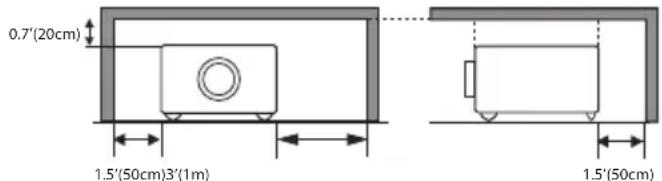
- Allowing the proper amount of space on the top, sides, and rear of the projector cabinet is critical for proper air circulation and cooling of the unit. The dimension shown here indicate the minimum space required. If the projector is to be built into a compartment or similarly enclosed, these minimum distances must be maintained.
SIDE and TOP REAR
text_image
0.7'(20cm) 1.5'(50cm)3'(1m) 1.5'(50cm)- Do not cover the ventilation slot on the projector. Heat build-up can reduce the service life of your projector, and can also be dangerous.
- If the projector is unused for an extended time, unplug the projector from the power outlet.
- Do not project the same image for a long time. The afterimage may remain on the LCD panels by the characteristic of panel.

CAUTION
DO NOT SET THE PROJECTOR IN GREASY, WET, OR SMOKY CONDITIONS SUCH AS IN A KITCHEN TO PREVENT A BREAKDOWN OR A DISASTER. IF THE PROJECTOR COMES IN CONTACT WITH OIL OR CHEMICALS, IT MAY BECOME DETERIORATED.
CAUTION
Not for use in a computer room as defined in the Standard for the Protection of Electronic Computer/Data Processing Equipment, ANSI/NFPA 75.
READ AND KEEP THIS OWNER'S MANUAL FOR LATER USE.
All the safety and operating instructions should be read before the product is operated.
Read all of the instructions given here and retain them for later use. Unplug this projector from AC power supply before cleaning. Do not use liquid or aerosol cleaners. Use a damp cloth for cleaning.
Follow all warnings and instructions marked on the projector.
For added protection to the projector during a lightning storm, or when it is left unattended and unused for long periods of time, unplug it from the wall outlet. This will prevent damage due to lightning and power line surges.
Do not expose this unit to rain or use near water... for example, in a wet basement, near a swimming pool, etc...
Do not use attachments not recommended by the manufacturer as they may cause hazards.
Do not place this projector on an unstable cart, stand, or table. The projector may fall, causing serious injury to a child or adult, and serious damage to the projector. Use only with a cart or stand recommended by the manufacturer, or sold with the projector. Wall or shelf mounting should follow the manufacturer's instructions, and should use a mounting kit approved by the manufacturers.
An appliance and cart combination should be moved with care. Quick stops, excessive force, and uneven surfaces may cause the appliance and cart combination to overturn.

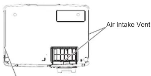
Slots and openings in the back and bottom of the cabinet are provided for ventilation, to ensure reliable operation of the equipment and to protect it from overheating.
The openings should never be covered with cloth or other materials, and the bottom opening should not be blocked by placing the projector on a bed, sofa, rug, or other similar surface. This projector should never be placed near or over a radiator or heat register.
This projector should not be placed in a built-in installation such as a book case unless proper ventilation is provided.
Never push objects of any kind into this projector through cabinet slots as they may touch dangerous voltage points or short out parts that could result in a fire or electric shock. Never spill liquid of any kind on the projector.
Do not install the projector near the ventilation duct of air-conditioning equipment.
This projector should be operated only from the type of power source indicated on the marking label. If you are not sure of the type of power supplied, consult your authorized dealer or local power company.
Do not overload wall outlets and extension cords as this can result in fire or electric shock. Do not allow anything to rest on the power cord. Do not locate this projector where the cord may be damaged by persons walking on it.
Do not attempt to service this projector yourself as opening or removing Covers may expose you to dangerous voltage or other hazards. Refer all servicing to qualified service personnel.
Unplug this projector from wall outlet and refer servicing to qualified service personnel under the following conditions:
a. When the power cord or plug is damaged or frayed.
b. If liquid has been spilled into the projector.
c. If the projector has been exposed to rain or water.
d. If the projector does not operate normally by following the operating instructions. Adjust only those controls that are covered by the operating instructions as improper adjustment of other controls may result in damage and will often require extensive work by a qualified technician to restore the projector to normal operation.
e. If the projector has been dropped or the cabinet has been damaged.
f. When the projector exhibits a distinct change in performance-this indicates a need for service.
When replacement parts are required, be sure the service technician has used replacement parts specified by the manufacturer that have the same characteristics as the original part. Unauthorized substitutions may result in fire, electric shock, or injury to persons.
Upon completion of any service or repairs to this projector, ask the service technician to perform routine safety checks to determine that the projector is in safe operating condition.
NOTE FOR CUSTOMERS IN THE US (Hg)LAMP(S) INSIDE THIS PRODUCT CONTAIN MERCURY AND MUST BE RECYCLED OR DISPOSED OF ACCORDING TO LOCAL, STATE OR FEDERAL LAWS.
Air Circulation
Openings in the cabinet are provided for ventilation. To ensure reliable operation of the product and to protect it from overheating, these openings must not be blocked or covered.

CAUTION
Hot air is exhausted from the exhaust vent. When using or installing the projector, the following precautions should be taken.
- Do not put any flammable object or spray can near the projector, hot air is exhausted from the ventilation holes.
- Keep the exhaust vent at least 3' (1 m) away from any objects.
- Do not touch a peripheral part of the exhaust vent, especially screws and metallic parts. These areas will become hot while the projector is being used.
- Do not put anything on the cabinet. Objects put on the cabinet will not only get damaged but also may cause fire hazard by heat.
- Make sure that there is no object under the projector to prevent from covering the bottom openings.
Cooling fans are provided to cool down the projector. The fans' running speed is changed according to the temperature inside the projector.
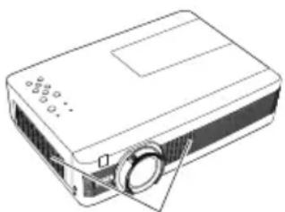
natural_image
Line drawing of a projector with a circular lens and screen (no text or symbols)Air intake Vent
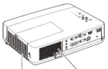
natural_image
Line drawing of a rectangular electronic device with ports and connectors (no text or symbols)Exhaust Vent (Hot air exhaust)
text_image
Air Intake VentExhaust Vent (Hot air exhaust)
Installing the Projector in Proper Position
Install the projector properly. Improper installation may reduce the lamp life and cause a fire hazard.
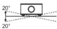
Do not roll the projector more than 20 degrees from side to side.
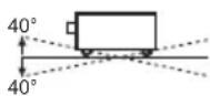
Do not pitch the projector more than 40 degrees from above and below.

Do not point the projector up to project an image.

Do not point the projector down to project an image.

Do not put the projector on either side to project an image.
Moving the Projector
When moving the projector, replace the lens cap and retract adjustable feet to prevent damage to the lens and cabinet.
When the projector is not in use for an extended period, put it into the supplied carrying case with the lens side up.

CAUTION
The carrying case (supplied) is intended for protection against dust and scratches on surface of the cabinet, and it is not designed to protect an appliance from external forces. Do not transport the projector by courier or any other transport service with this case, otherwise the projector can be damaged. When handling the projector, do not drop, bump, subject it to strong forces, or put other things on the cabinet.

CAUTION IN CARRYING OR TRANSPORTING THE PROJECTOR
- Do not drop or bump the projector, otherwise damages or malfunctions may result.
- When carrying the projector, use a suitable carrying case.
- Do not transport the projector by courier or any other transport service in an unsuitable transport case. This may cause damage to the projector. For information about transporting the projector by courier or any other transport service, consult your dealer.
- Do not put the projector in a case before the projector is cooled enough.
Federal Communications Commission Notice
Note: This equipment has been tested and found to comply with the limits for a Class B digital device, pursuant to Part 15 of the FCC Rules. These limits are designed to provide reasonable protection against harmful interference in a residential installation. This equipment generates, uses, and can radiate radio frequency energy, and if not installed and used in accordance with the instructions, may cause harmful interference to radio communications. However, there is no guarantee that interference will not occur in a particular installation. If this equipment does cause harmful interference to radio or television reception, which can be determined by turning the equipment off and on, the user is encouraged to try to correct the interference by one or more of the following measures:
– Reorient or relocate the receiving antenna.
– Increase the separation between the equipment and receiver.
- Connect the equipment into an outlet on a circuit different from that to which the receiver is connected.
- Consult the dealer or an experienced radio/TV technician for help.
Use of shielded cable is required to comply with class B limits in Subpart B of Part 15 of FCC Rules.
Do not make any changes or modifications to the equipment unless otherwise specified in the instructions. If such changes or modifications should be made, you could be required to stop operation of the equipment.
Model Number : LC-WB200
Trade Name : EIKI
Responsible party : EIKI International, Inc.
Address : 30251 Esperanza Santa Margaria CA 92688-2123
Telephone No. : 800-242-3454 (949-457-0200)
AC Power Cord Requirement
The AC Power Cord supplied with this projector meets the requirement for use in the country you purchased it.
AC Power Cord for the United States and Canada:
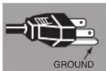
AC Power Cord used in the United States and Canada is listed by the Underwriters Laboratories (UL) and certified by the Canadian Standard Association (CSA). AC Power Cord has a grounding-type AC line plug. This is a safety feature to be sure that the plug will fit into the power outlet. Do not try to defeat this safety feature. Should you be unable to insert the plug into the outlet, contact your electrician.
AC Power Cord for the United Kingdom:
This cord is already fitted with a moulded plug incorporating a fuse, the value of which is indicated on the pin face of the plug. Should the fuse need to be replaced, an ASTA approved BS 1362 fuse must be used of the same rating, marked thus ☑. If the fuse cover is detachable, never use the plug with the cover omitted. If a replacement fuse cover is required, ensure it is of the same colour as that visible on the pin face of the plug (i.e. red or orange). Fuse covers are available from the Parts Department indicated in your User Instructions.
If the plug supplied is not suitable for your socket outlet, it should be cut off and destroyed.
The end of the flexible cord should be suitably prepared and the correct plug fitted.
WARNING : A PLUG WITH BARED FLEXIBLE CORD IS HAZARDOUS IF ENGAGED IN A LIVE SOCKET OUTLET.
The Wires in this mains lead are coloured in accordance with the following code:
Green-and-yellow ..... Earth
Blue ....Neutral
Brown.....Live
As the colours of the wires in the mains lead of this apparatus may not correspond with the coloured markings identifying the terminals in your plug proceed as follows:
The wire which is coloured green-and-yellow must be connected to the terminal in the plug which is marked by the letter E or by the safety earth symbol or coloured green or green-and-yellow.
The wire which is coloured blue must be connected to the terminal which is marked with the letter N or coloured black.
The wire which is coloured brown must be connected to the terminal which is marked with the letter L or coloured red.
WARNING: THIS APPARATUS MUST BE EARTHED.
THE SOCKET-OUTLET SHOULD BE INSTALLED NEAR THE EQUIPMENT AND EASILY ACCESSIBLE.
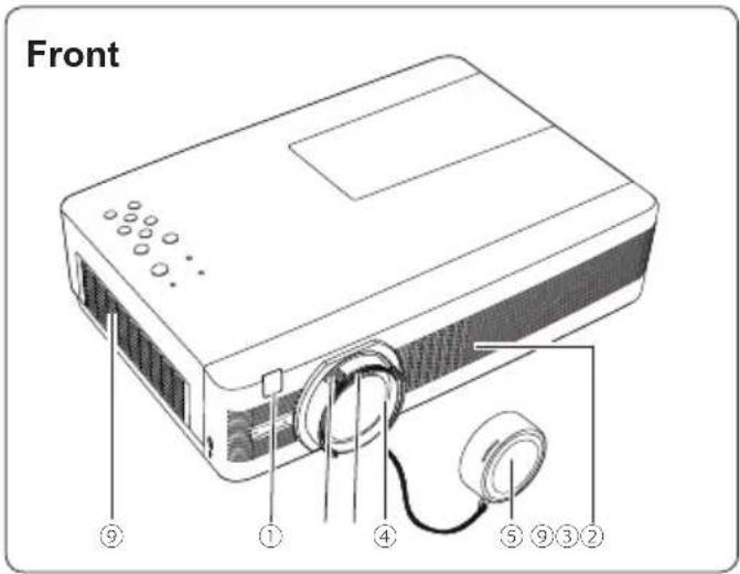
text_image
Front ⑨ ① ④ ⑤ ⑨ ③ ②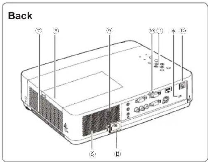
text_image
Back ⑦ ⑧ ⑨ ⑩ ⑪ * ⑫ ⑥ ⑬ ⑬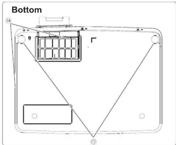
text_image
Bottom ⑭ ⑬① Infrared Remote Receiver
② Zoom Ring
③ Focus Ring
④ Projection Lens

CAUTION
Do not cover the light beam in front of the lens. High temperature from light beam may damage the lens.
⑤ Lens Cap
(See page 62 for attaching.)

CAUTION
Do not turn on a projector with lens cap attached. High temperature from light beam may damage lens cap and result in fire hazard.
⑥ Speaker
⑦ Exhaust Vents

CAUTION
Hot air is exhausted from the exhaust vent. Do not put heat-sensitive objects near this side.
⑧ Lamp Cover
⑨ Air Intake Vents
⑩ Terminals and Connectors
⑪ Top Controls and Indicators
⑫ LAN Connection Terminal
⑬ Power Cord Connector
⑭ Filter Covers
⑮ Adjustable Feet
√ Note:
⑫ LAN Connection Terminal is for the Network function. Refer to the owner's manual of "Network Set-up and Operation".
\* Kensington Security Slot
This slot is for a Kensington lock used to deter theft of the projector.
*Kensington is a registered trademark of ACCO Brands Corporation.
Rear Terminal
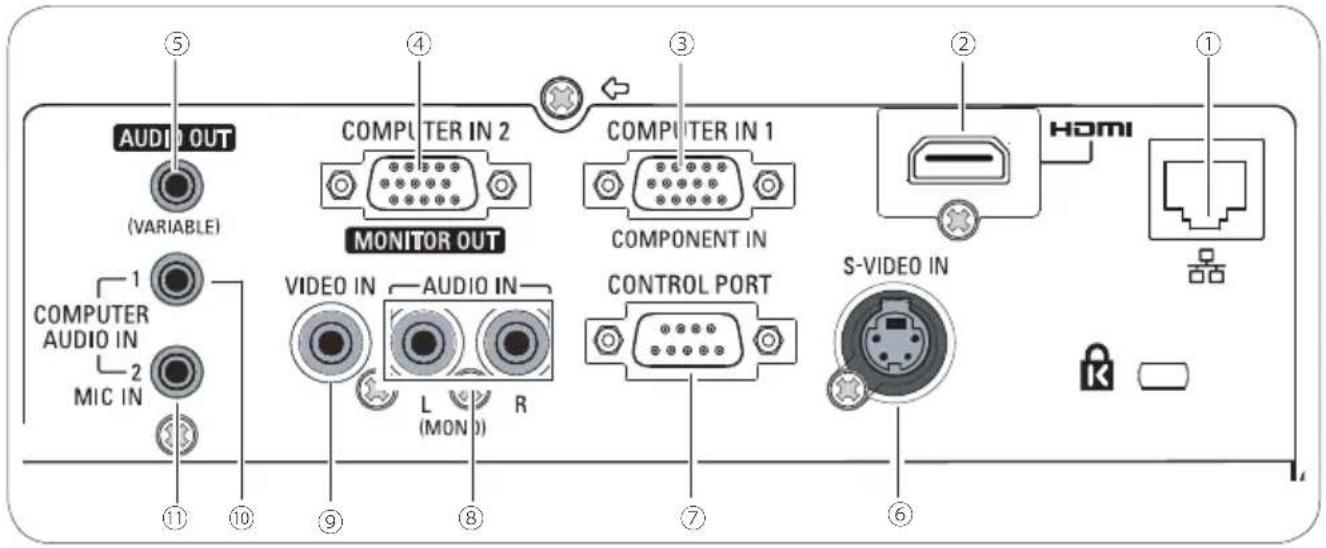
text_image
AUDIO OUT (VARIABLE) 1 COMPUTER AUDIO IN 2 MIC IN ⑤ ④ ③ ② HDMI MONITOR OUT COMPUTER IN 2 COMPONENT IN VIDEO IN AUDIO IN L (MON) R CONTROL PORT S-VIDEO IN① LAN Connection Terminal
Connect the LAN cable (refer to the owner's manual of "Network Set-up and Operation").
② HDMI Terminal
Connect the HDMI signal (including sound signal) from video equipment or from computer to this terminal (pp.14, 15).
HDMI is registered trademarks of HDMI Licensing, LLC.
③ COMPUTER IN 1 / COMPONENT IN
Connect output signal from a computer, RGB scart 21-pin video output or component video output to this terminal (pp.14,16).
④ COMPUTER IN 2 / MONITOR OUT
- Connect computer output to this terminal (p.14).
- This terminal can be used to output the incoming analog RGB and Component signal from COMPUTER IN 1/COMPONENT IN terminal to the other monitor (pp.14,16).
Connect an external audio amplifier to this jack (pp.14-16).
This terminal outputs sound from AUDIO IN terminal (⑧, ⑩ or ⑪), or HDMI terminal (2) (digital audio).
Never plug headphones and earphones into this jack.
⑥ S-VIDEO IN
Connect the S-VIDEO output signal from video equipment to this jack (p.15).
⑦ CONTROL PORT
When controlling the projector with RS-232C, connect the control equipment to this connector with the serial control cable.
⑧ AUDIO IN
Connect the audio output signal from video equipment connected to ⑥ or ⑨ to this jack. For a mono audio signal (a single audio jack), connect it to the L (MONO) jack (p.15).
⑨ VIDEO IN
Connect the composite video output signal to this jack (p.15).
⑩ COMPUTER AUDIO IN 1
Connect the audio output (stereo) from a computer or video equipment connected to ② or ③ to this jack (pp.14, 16).
⑪ COMPUTER AUDIO IN 2 (MIC IN)
Connect the audio output (stereo) from a computer or video equipment connected to ④ to this jack. Or connect the MIC to the this jack (pp.14, 16).
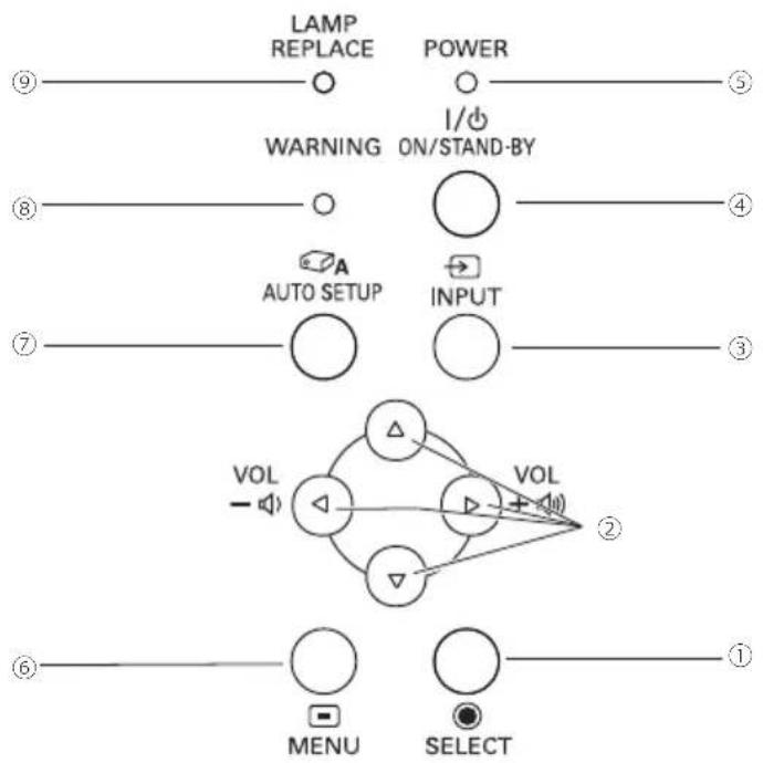
Top Control
flowchart
graph TD
    A["LAMP REPLACE"] --> B["POWER"]
    B --> C["WARNING ON/STAND-BY"]
    C --> D["A AUTO SETUP"]
    D --> E["INPUT"]
    E --> F["VOL"]
    F --> G["2"]
    G --> H["MENU SELECT"]
    H --> I["1"]
    style A fill:#fff,stroke:#000
    style B fill:#fff,stroke:#000
    style C fill:#fff,stroke:#000
    style D fill:#fff,stroke:#000
    style E fill:#fff,stroke:#000
    style F fill:#fff,stroke:#000
    style G fill:#fff,stroke:#000
    style H fill:#fff,stroke:#000
    style I fill:#fff,stroke:#000
① SELECT button
- Execute the selected item (p.21).
- Expand or compress the image in the Digital zoom mode (p.35).
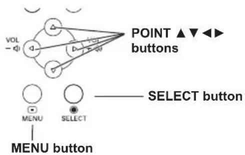
② POINT ▲ ▼ ◀▶ (VOLUME-/+ ) buttons
- Select an item or adjust the value in the On-Screen Menu (p.21).
- Pan the image in the Digital zoom +/- mode (p.35).
- Adjust the volume level (Point ◀▶ buttons) (p.24).
③ INPUT button
Select an input source (pp.27, 36-37).
④ ON/STAND-BY button
Turn the projector on or off (pp.18-20).
⑤ POWER indicator
- Lights red when the projector is in stand-by mode.
– Lights green during operations. - Blinks green in the Power management mode (p.51).
⑥ MENU button
Open or close the On-Screen Menu (p.21).
⑦ AUTO SETUP button
Execute the setting of Auto setup (includes Input search, Auto PC adj. and Auto Keystone functions) in the setting menu. (pp.23, 45).
⑧ WARNING indicator
– Lights red when the projector detects an abnormal condition.
- Blinks red when the internal temperature of the projector exceeds the operating range (pp.60, 70).
⑨ LAMP REPLACE indicator
Lights yellow when the projection lamp reaches its end of life (pp.63, 70).
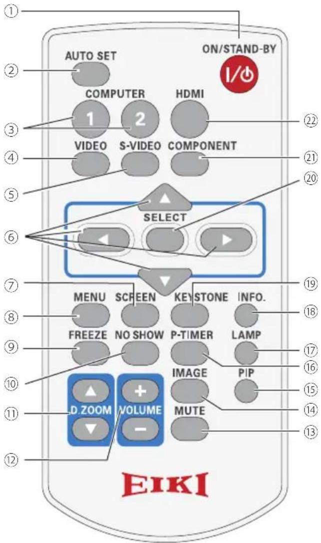
Remote control
text_image
AUTO SET ON/STAND-BY COMPUTER HDMI 1 2 VIDEO S-VIDEO COMPONENT SELECT MENU SCREEN KEYSTONE INFO. FREEZE NO SHOW P-TIMER LAMP IMAGE PIP D.ZOOM VOLUME MUTE EIKI① ON/STAND-BY button
Turn the projector on or off. (pp.18-20)
② AUTO SET button
Execute the setting of Auto setup (includes Input search, Auto PC adj. and Auto Keystone functions) in the setting menu. (pp.23, 45)
③ COMPUTER 1/2 buttons
Select the COMPUTER 1 or COMPUTER 2 input source. (pp.27, 37)
√ Note:
To ensure safe operation, please observe the following precautions:
- Do not bend, drop or expose the remote control to moisture or heat.
- For cleaning, use a soft dry cloth. Do not apply benzene, thinner, spray, or any chemical material.
④ VIDEO button
Select the VIDEO input source. (p.36)
⑤ S-VIDEO button
Select the S-VIDEO input source. (p.36)
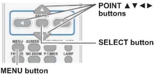
⑥ Point ▲▼◀▶ buttons
- Select an item or adjust the value in the On-Screen Menu. (p.24)
- Pan the image in the Digital zoom +/- mode. (p.35)
⑦ SCREEN button
Select a screen mode. (pp.26, 34-35, 42-43)
⑧ MENU button
Open or close the On-Screen Menu. (p.24)
⑨ FREEZE button
Freeze the picture on the screen. (p.25)
⑩ NO SHOW button
Temporarily turn off the image on the screen. (p.26)
⑪ D.ZOOM ▲▼ buttons
Zoom in and out the images. (pp.25, 35)
⑫ VOLUME +/- buttons
Adjust the volume level. (p.24)
⑬ MUTE button
Mute the sound. (p.24)
⑭ IMAGE button
Select the image mode. (pp.26, 32, 40)
⑮ PIP button
Operate the Picture in Picture function (p.25).
⑯ P-TIMER button
Operate the P-timer function. (pp.26, 52)
⑰ LAMP button
Select a lamp mode. (pp.25, 54)
⑱ INFO. button
Operate the information function. (p.59)
⑲ KEYSTONE button
Correct keystone distortion. (p.23)
⑳ SELECT button
- Execute the selected item. (p.21)
- Zoom in or out the image in Digital zoom mode. (p.35)
②1 COMPONENT button
Select the COMPONENT input source. (p.37)
②2 HDMI button
Select the HDMI input source. (p.37)
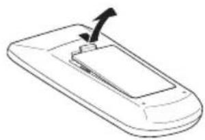
Remote control Battery Installation
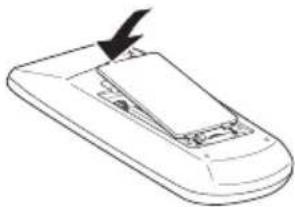
1 Open the battery compartment lid.
2 Install new batteries into the compartment.
3 Replace the compartment lid.
natural_image
Line drawing of a handheld device with an arrow pointing to the screen (no text or symbols)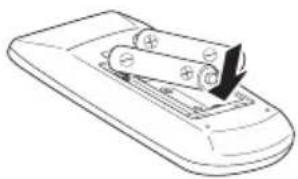
natural_image
Line drawing of a remote control device with a handle and wheels (no text or symbols)Two AAA size batteries
For correct polarity (+ and -), be sure battery terminals are in contact with pins in compartment.
natural_image
Line drawing of a computer mouse with a black arrow pointing to the internal part (no text or symbols)
WARNING
To ensure safe operation, please observe the following precautions :
- Use two (2) AAA or LR03 type alkaline batteries.
• Always replace batteries in sets. - Do not use a new battery with a used battery.
- Avoid contact with water or liquid.
- Do not expose the remote control to moisture or heat.
- Do not drop the remote control.
- If the battery has leaked on the remote control, carefully wipe the case clean and install new batteries.
- Risk of an explosion if battery is replaced by an incorrect type.
- Dispose of used batteries according to the instructions or your local disposal rule or guidelines.
Remote control Operating Range
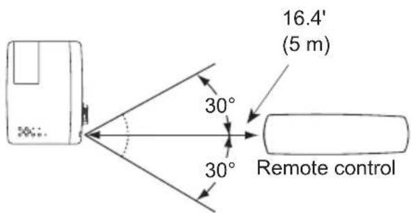
Point the remote control toward the projector (Infrared Remote Receiver) when pressing the buttons. Maximum operating range for the remote control is about 16.4'(5 m) and 60 degrees in front of the projector.
text_image
16.4' (5 m) 30° 30° Remote controlRemote Control Code
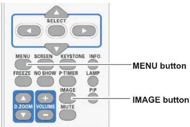
The 2 different remote control codes (Code 1–Code 2) are assigned to this projector. Switching the remote control codes prevents interference from other remote controls when several projectors or video equipment next to each other are operated at the same time. Change the remote control code for the projector first before changing that for the remote control. See "Remote control" in the Setting Menu on page 54.
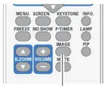
Press and hold the MENU and IMAGE buttons for more than five seconds to switch between the Code 1 and Code 2. The initial code is set to Code 1.
text_image
SELECT MENU SCREEN KEYSTONE INFO. FREEZE NO SHOW P-TIMER LAMP D.ZOOM VOLUME IMAGE PIP MUTE MENU button IMAGE buttonPositioning the Projector
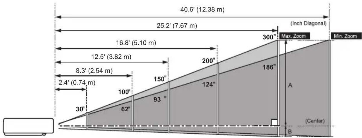
For projector positioning, see the figures below. The projector should be set perpendicularly to the plane of the screen.
√Note:
- The brightness in the room has a great influence on picture quality. It is recommended to limit ambient lighting in order to obtain the best image.
• All measurements are approximate and may vary from the actual sizes.
other
| Section | Width (m) | | ------- | --------- | | Top Section | 40.6' (12.38 m) | | Middle Section | 25.2' (7.67 m) | | Bottom Section | 30" (62") | | Center Section | 93" (150") | | Total Width | 12.5' (3.82 m) | | Total Height | 8.3' (2.54 m) | | Total Base Width | 2.4' (0.74 m) | | Maximum Zoom Height | 300" (186") | | Minimum Zoom Height | 300" (186") || A:B = 49:1 | |||||
| Screen Size(W x H) mm16:10 aspect ratio | 30" 100" | 150" 200" 300" | |||
| 646 x 404 2 | 154 x 1346 323 | x 2019 4308 x | 2692 6462 x 4039 | ||
| Zoom (max) | 2.4'(0.74 m) | 8.3'(2.54 m) | 12.5'(3.82 m) | 16.8'(5.10 m) | 25.2'(7.67 m) |
| Zoom (min) | 4.0'(1.21 m) | 13.5'(4.11 m) | 20.3'(6.18 m) | 27.1'(8.25 m) | 40.6'(12.38 m) |
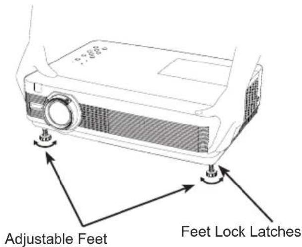
Adjustable Feet
Projection angle can be adjusted up to 12.0 degrees with the adjustable feet.
Lift the front of the projector and press the feet lock latches on both side of the projector.
Release the feet lock latches to lock the adjustable feet and rotate the adjustable feet to a proper height and tilt.
Keystone distortion can be adjusted automatically with the Auto setup function or manually by using the remote control or the menu operation (see pages 23, 35, 43).
text_image
Adjustable Feet Feet Lock LatchesConnecting to a Computer
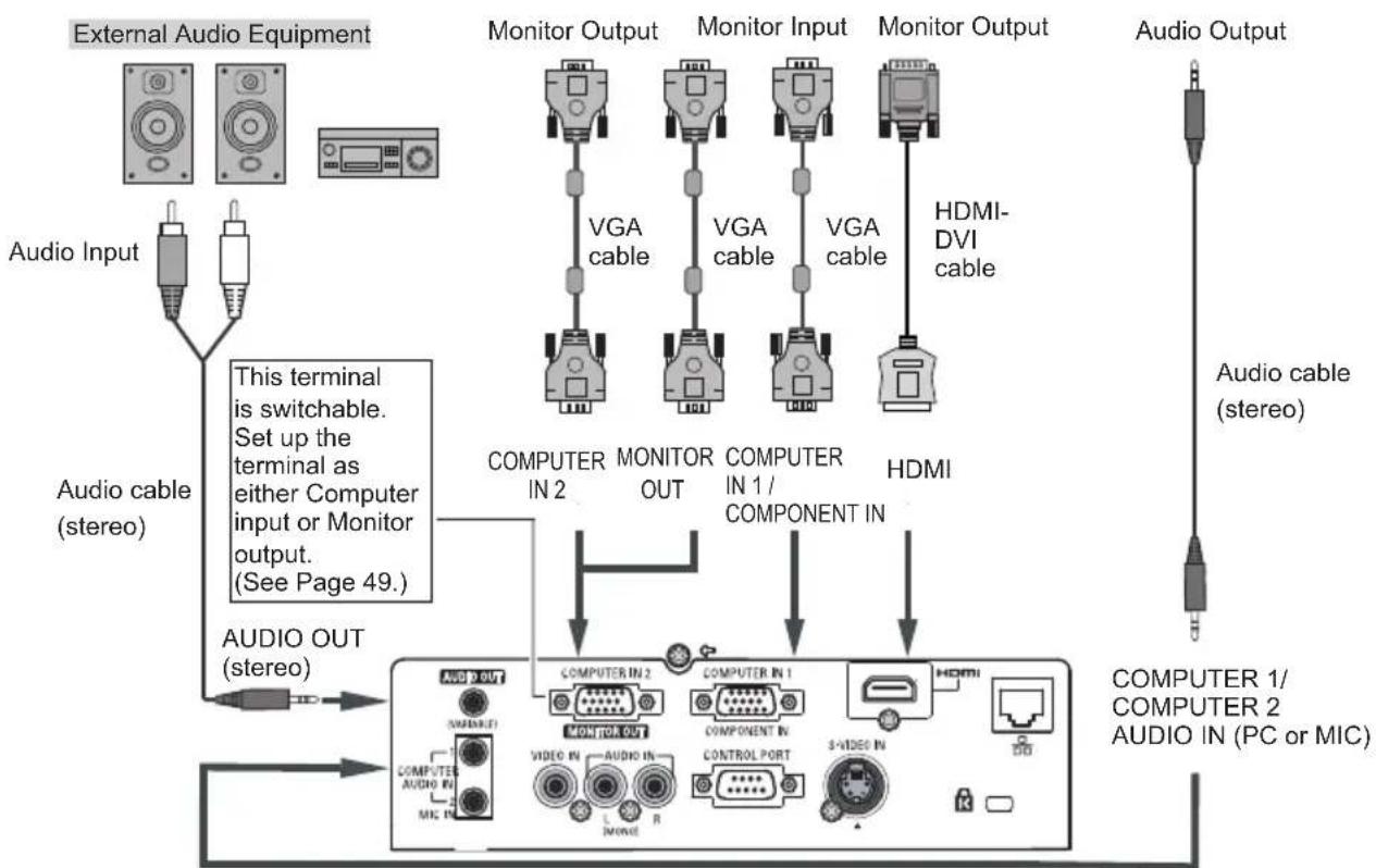
Cables used for connection
• VGA Cables (Mini D-sub 15 pin) *
- Audio Cable
• HDMI-DVI cable
(*One cable is supplied; other cables are not supplied with the projector.)
natural_image
Line drawing of a desktop computer setup with monitor, keyboard, and tower (no text or symbols)
natural_image
Illustration of a laptop computer with blank screen and keyboard (no text or symbols)
flowchart
graph TD
    A["External Audio Equipment"] --> B["Monitor Output"]
    B --> C["VGA cable"]
    C --> D["Monitor Input"]
    D --> E["VGA cable"]
    E --> F["HDMI-DVI cable"]
    G["Audio Input"] --> H["Computer IN 2"]
    H --> I["MONITOR OUT"]
    I --> J["COMPUTER IN 1 / COMPONENT IN"]
    J --> K["HDMI"]
    L["Audio cable (stereo)"] --> M["AUDIO OUT (stereo)"]
    M --> N["COMPUTER IN 2"]
    N --> O["MONITOR OUT"]
    O --> P["COMPUTER IN 1"]
    P --> Q["HDMI"]
    R["Computer 1/COMPUTER 2 AUDIO IN (PC or MIC)"] --> S["Audio Output"]
√ Note:
- When the MIC function is set to Off in the Sound menu, the MIC function is disabled. (p. 24)
- When MIC is set to On in Sound Menu, COMPUTER AUDIO IN 1, COMPUTER AUDIO IN 2 / MIC IN and AUDIO IN(L/R) terminals can be connected at the same time. At this time, COMPUTER AUDIO IN 2 terminal as MIC input. (p. 24)
- Input sound to the COMPUTER AUDIO IN 1, COMPUTER AUDIO IN 2 / MIC IN terminals when using the COMPUTER IN 2 / MONITOR OUT and the COMPUTER IN 1/ COMPONENT IN terminal as input.
- When the AUDIO OUT is plugged-in, the projector's built-in speaker is not available.
- When the cable is of the longer variety, it is advisable to use the COMPUTER IN 1 / COMPONENT IN and not the COMPUTER IN 2/ MONITOR OUT.

Unplug the power cords of both the projector and external equipment from the AC outlet before connecting cables.
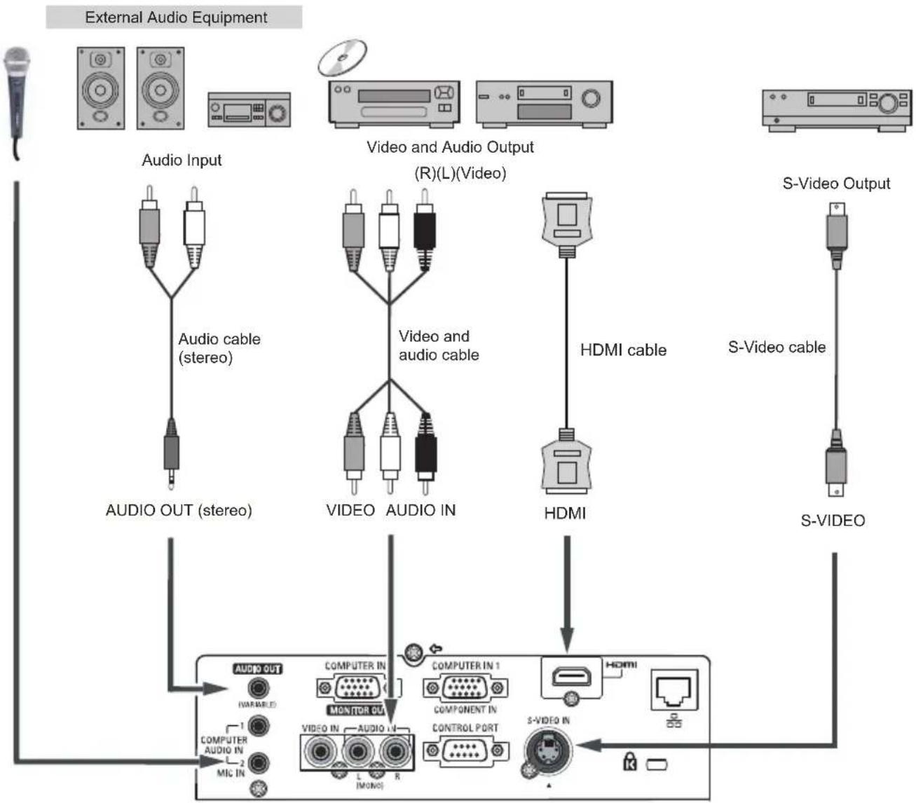
Connecting to Video Equipment
Cables used for connection
• Video and Audio Cable (RCA x 3)
- S-VIDEO Cable
- Audio Cable
- HDMI Cable
(Cables are not supplied with the projector.)
flowchart
graph TD
    A["External Audio Equipment"] --> B["Audio Input"]
    B --> C["Audio cable (stereo)"]
    C --> D["AUDIO OUT (stereo)"]
    D --> E["VIDEO"]
    E --> F["VIDEO and audio cable"]
    F --> G["VIDEO"]
    G --> H["HDMI"]
    H --> I["S-Video Output"]
    I --> J["S-Video cable"]
    J --> K["S-VIDEO"]
    K --> L["Computer IN 1"]
    L --> M["COMPONENT IN"]
    M --> N["CONTROL PORT"]
    N --> O["S-VIDEO IN"]
    O --> P["Micro"]
    P --> Q["MONITOR OUT"]
    Q --> R["VIDEO IN"]
    R --> S["AUDIO IN"]
    S --> T["COMPUTER IN"]
    T --> U["COMPUTER OUT"]
    U --> V["VIDEO IN"]
    V --> W["L (Mono)"]
    W --> X["R (Mono)"]
    X --> Y["Micro In"]
√ Note:
When the AUDIO OUT is plugged-in, the projector's built-in speaker is not available.

Unplug the power cords of both the projector and external equipment from the AC outlet before connecting cables.
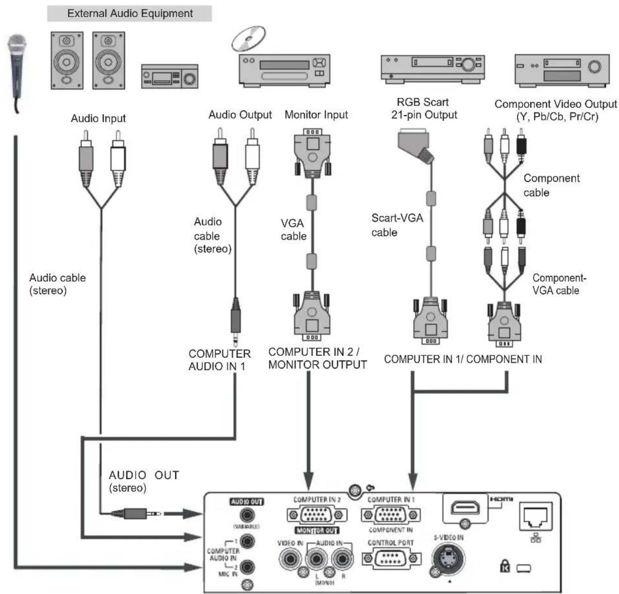
Connecting to Component Video and RGB (Scart) Equipment
Cables used for connection
- Audio Cables
- Scart-VGA Cable
- VGA Cable
- Component Cable
- Component-VGA Cable
(Cables are not supplied with this projector.)
flowchart
graph TD
    A["External Audio Equipment"] --> B["Audio Input"]
    A --> C["Audio Output"]
    A --> D["Monitor Input"]
    A --> E["RGB Scart 21-pin Output"]
    A --> F["Component Video Output (Y, Pb/Cb, Pr/Cr)"]
    B --> G["Audio cable (stereo)"]
    C --> H["Audio cable (stereo)"]
    D --> I["VGA cable"]
    E --> J["Scart-VGA cable"]
    F --> K["Component cable"]
    G --> L["COMPUTER AUDIO IN 1"]
    H --> M["COMPUTER IN 2 / MONITOR OUTPUT"]
    I --> N["COMPUTER IN 1/ COMPONENT IN"]
    J --> O["COMPUTER IN 1"]
    K --> P["COMPUTER IN 1/ COMPONENT IN"]
    L --> Q["AUDIO OUT (stereo)"]
    M --> R["AUDIO OUT (VARIABLE)"]
    N --> S["AUDIO OUT (MONO)"]
    O --> T["AUDIO OUT (R/R)"]
    P --> U["S-VIDEO IN"]
    Q --> V["MIC IN"]
    R --> W["L MONO1"]
    S --> X["VIDEO IN"]
    T --> Y["CONTROL PORT"]
    U --> Z["HDMI"]
√ Note:
- When the AUDIO OUT is plugged-in, the projector's built-in speaker is not available.
• See page 74 for ordering optional cables.

Unplug the power cords of both the projector and external equipment from the AC outlet before connecting cables.
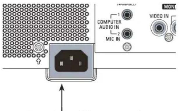
Connecting the AC Power Cord
This projector uses nominal input voltages of 100-240 V AC and it automatically selects the correct input voltage. It is designed to work with single-phase power systems having a grounded neutral conductor. To reduce the risk of electrical shock, do not plug into any other type of power system.
If you are not sure of the type of power being supplied, consult your authorized dealer or service center.
Connect the projector with all peripheral equipment before turning the projector on.
text_image
COMPUTER AUDIO IN MIC IN MONI VIDEO INConnect the AC power cord (supplied) to the projector.

CAUTION
The AC outlet must be near this equipment and must be easily accessible.
√ Note:
Unplug the AC power cord when the projector is not in use. When this projector is connected to an outlet with the AC power cord, it is in Stand-by mode and consumes a little electric power.
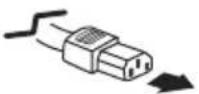
| NOTE ON THE POWER CORDAC power cord must meet requirement of the country where you use the projector.Confirm the AC plug type with the chart below and proper AC power cord must be used.If supplied AC power cord does not match your AC outlet, contact your sales dealer. | |||
| Projector side | AC outlet side | ||
 To power cordconnector on yourprojector. To power cordconnector on yourprojector. | For the U.S.A. and Canada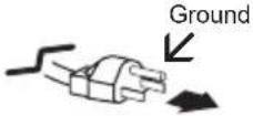 To the AC outlet.(120 V AC) To the AC outlet.(120 V AC) | For Continental Europe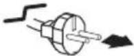 To the AC outlet.(200 - 240 V AC) To the AC outlet.(200 - 240 V AC) | For the U.K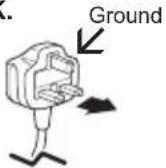 To the AC outlet.(200 - 240 V AC) To the AC outlet.(200 - 240 V AC) |
Turning On the Projector
1 Complete peripheral connections (with a computer, VCR, etc.) before turning on the projector.
2 Connect the projector's AC power cord into an AC outlet. The POWER indicator lights red. Open the lens cap.
3 Press the ON/STAND-BY button on the top control or on the remote control. The POWER indicator lights green and the cooling fans start to operate. The preparation display appears on the screen and the countdown starts.
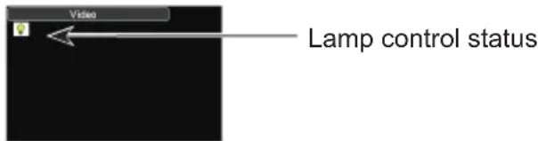
4 After the countdown, the input source that was selected the last time and the Lamp control status icon (p.54) appear on the screen.
5 If there is no signal input when start on the projector, or the current signal is missed while operating the projector, the Video/PC selection window will be displayed on the screen, please move the pointer to input source desired by pressing the Point ▲▼ buttons and press the SEL button. And then follow the input signal guidance window to correct the signal and connection.
If the projector is locked with a PIN code, PIN code input dialog box will appear. Enter the PIN code as instructed on the next page.

text_image
16 EIKI http://www.eiki.comThe preparation display will disappear after 30 seconds.
Selected Input Source and Lamp control
text_image
Video Lamp control status(See page 54 for Lamp control status.)
√Note:
The Filter warning and Lamp replacement icons may appear on the screen depending on the usage state of the projector.
PC Selection
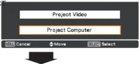
text_image
Project Video Project Computer MENU Cancel Move SELECT SelectGuidance for PC Input
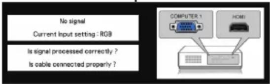
text_image
No signal Current Input setting : RGB Is signal processed correctly ? Is cable connected properly ? COMPUTER 1 HOM!√Note:
- When the Logo select function is set logo will not be shown on the screen (p.46).
- When Countdown off or Off is selected in the Display function, the preparation display will not be shown on the screen (p.46).
- When the Input search function is set to On 2, the input signal will be searched automatically (p.45).
- When Off is selected in the Display function, the Video/PC selection window and the input signal guidance window are not shown on the screen (p.46).
Video Selection
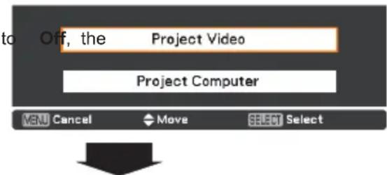
text_image
to Off, the Project Video Project Computer MENU Cancel Move SELECT SelectGuidance for Video Input
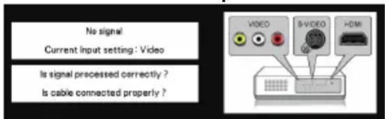
text_image
No signal Current Input setting: Video Is signal processed correctly ? Is cable connected properly?Enter a PIN code
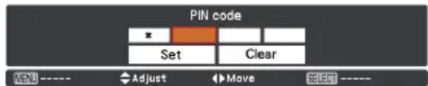
Use the Point ▲▼ buttons to enter a number. Press the Point ▶ button to fix the number and move the red frame pointer to the next box. The number changes to *. If you fixed an incorrect number, use the Point ◀ button to move the pointer to the number you want to correct, and then enter the correct number.
Repeat this step to complete entering a four-digit number.
After entering the four-digit number, move the pointer to "Set". Press the SELECT button so that you can start to operate the projector.
If you entered an incorrect PIN code, PIN code and the number (***** ) will turn red for a moment. Enter the correct PIN code all over again.
What is PIN code?
PIN (Personal Identification Number) code is a security code that allows the person who knows it to operate the projector. Setting a PIN code prevents unauthorized use of the projector.
A PIN code consists of a four-digit number. Refer to the PIN code lock function in the Setting Menu on pages 55-56 for locking operation of the projector with your PIN code.
PIN Code Input Dialog Box
text_image
PIN code Set Clear MENU ---- Adjust Move SELET ----
After the OK icon disappears, you can operate the projector.
OK
√Note:
- If the PIN code number is not entered or wrong PIN code number is entered within three minutes after the PIN code dialog box appeared, the projector will be turned off automatically.
- The “1234” is set as the initial PIN code at the factory.

CAUTION ON HANDLING PIN CODE
If you forget your PIN code, the projector can no longer be started. Take a special care in setting a new PIN code, write down the number in a column on page 78 of this manual and keep it on hand. Should the PIN code be missing or forgotten, consult your dealer or service center.
Turning Off the Projector
1 Press the ON/STAND-BY button on the top control or on the remote control, and Power off? appears on the screen.
2 Press the ON/STAND-BY button again to turn off the projector. The POWER indicator starts to blink red, and the cooling fans keep running. (You can select the level of fans' quietness and speed. See "Fan" on page 56.) At this time, you can unplug the AC power cord even if the fans are still running.
3 When the projector has cooled down enough, the POWER indicator stops blinking and you can turn on the projector.

TO MAINTAIN THE LIFE OF THE LAMP, ONCE YOU TURN THE PROJECTOR ON, WAIT AT LEAST FIVE MINUTES BEFORE TURNING IT OFF.

DO NOT OPERATE THE PROJECTOR CONTINUOUSLY WITHOUT REST. CONTINUOUS USE MAY RESULT IN SHORTENING THE LAMP LIFE. TURN OFF THE PROJECTOR AND LET IT STAND FOR ABOUT AN HOUR IN EVERY 24 HOURS.
√Note:
- When the Direct on function is set to On, the projector will be turned on automatically by connecting the AC power cord to an AC outlet (p.51).
- The running speed of cooling fans is changed according to the temperature inside the projector.
- Do not put the projector in a case before the projector is cooled enough.
- If the WARNING indicator blinks or lights red, see "WARNING indicator" on page 60.
- While the POWER indicator is blinking, the lamp is being cooled down and the projector cannot be turned on. Wait until the POWER indicator stops blinking to turn on the projector again.
- For assisting the cooling fans' operation, the projector is equipped with a large capacitor. While the projector is operating, the capacitor charges electricity. When disconnecting the AC plug from AC outlet, cooling fans start to run 1 minute until the capacitor is discharged.
- The projector can be turned on after the POWER indicator turns red. The waiting time to restart will be shortened when the normal power-off processing for fan cooling is completed, compared with the time the AC power cord is immediately unplugged after the power-off.
Power off?
Power off? disappears after 4 seconds.
Direct Off Function
You can disconnect the power cord from the wall outlet or turn off the breaker even during projection without pressing the ON/STAND-BY button.
√Note:
When using the Direct Off function, you can not restart the projector immediately after the power is disconnected. If the external power supply is suddenly cut off, the fans stop immediately. The lamp remains high temperature and needs to be cooled.
How to Operate the On-Screen Menu
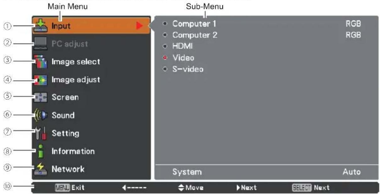
The projector can be adjusted or set via the On-Screen Menu. The menus have a hierarchical structure, with a main menu that is divided into submenus, which are further divided into other submenus. For each adjustment and setting procedure, refer to respective sections in this manual.
1 Press the MENU button on the top control or the remote control to display the On-Screen Menu.
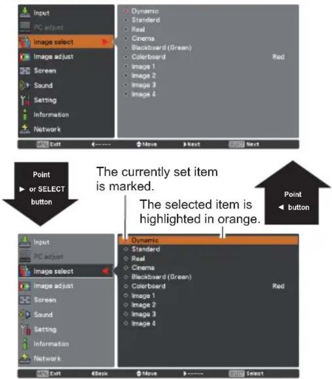
2 Use the Point ▲▼ buttons to highlight or select a main menu item. Press the Point ▶ or the SELECT button to access the submenu items. (The selected item is highlighted in orange.)
3 Use the Point ▲▼ buttons to select the desired submenu item and press the SELECT button to set or access the selected item.
4 Use the Point ▲▼◀▶ buttons to adjust the setting or switch between each option and press the SELECT button to activate it and return to the submenu.
5 Press the Point ◀ button to return to the main menu. Press the MENU button to exit the On-Screen Menu.
Top Control
text_image
VOL POINT ▲▼◀▶ buttons —— SELECT button MENU SELECT MENU buttonRemote control
text_image
POINT buttons SELECT button MENU SCREEN FRI ZE ND SHOW P-TIMER LAMP MENU buttonOn-Screen Menu
text_image
Input PC adjust Image select Image adjust Screen Sound Setting Information Network Dynamic Standard Real Cinema Blackboard (Green) Colorboard Image 1 Image 2 Image 3 Image 4 Red Exit Move Next Next Point or SELECT button The currently set item is marked. The selected item is highlighted in orange. Point button Input PC adjust Image select Image adjust Screen Sound Setting Information Network Dynamic Standard Real Cinema Blackboard (Green) Colorboard Image 1 Image 2 Image 3 Image 4 Red Exit Back Move SelectMain Menu
For detailed functions of each menu, see "Menu Tree" on pages 68-69.
text_image
Main Menu Input PC adjust Image select Image adjust Screen Sound Setting Information Network Sub-Menu Computer 1 RGB Computer 2 RGB HDMI Video S-video System Auto MENU Exit ←---- Move Next SELEOT Next① Input
Used to select an input source from Computer 1, Computer 2, HDMI, Video or S-video. (pp.27, 37)
② PC adjust
Select Auto PC adj., Fine sync, Total dots, Horizontal, Vertical, Current mode, Clamp, Display area H, Display area V, Reset, Mode free and Store to adjust the parameters to match with the PC input signal format. (pp.29-31)
③ Image select
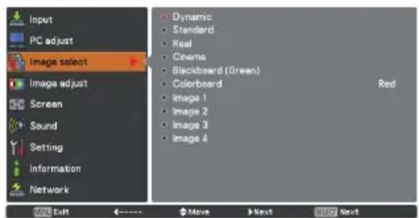
For both of computer and Video sources, used to select an image mode from among Dynamic, Standard, Real, Cinema, Blackboard(Green), Colorboard and Image 1-4. (pp.32, 39)
④ Image adjust
For Computer source, used to adjust computer image [Contrast, Brightness, Color temp., White balance (R/G/B), Sharpness, Gamma, Reset and Store]. (p.33)
For VIDEO source, used to adjust picture image [Contrast, Brightness, Color, Tint, Color temp., White balance (R/G/B), Sharpness, Gamma, Noise reduction, Progressive, Reset and Store]. (pp.40-41)
⑤ Screen
For Computer source, used to adjust size of the image [ Normal, Full, Wide(16:9), Zoom, True, Custom, Custom adj., Digital zoom +/- , Keystone, Ceiling, Rear, Screen aspect and Reset]. (pp.34-35)
For VIDEO source, used to set size of image [Normal, Full, Wide(16:9), Zoom, Natural wide, Custom, Custom adj., Keystone, Ceiling, Rear, Screen aspect and Reset]. (pp.42-43)
⑥ Sound
Used to adjust the volume or mute the sound or set configurations to the MIC functions (p.24).
⑦ Setting
Used to set the projector's operating configurations. (pp.44-58)
⑧ Information
Display the input source information. (p.59)
⑨ Network
See owner's manual of "Network Set-up and Operation".
⑩ Guide
The key operation is displayed.
Zoom and Focus Adjustment
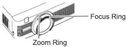
Rotate the Zoom Ring to zoom in and out. Rotate the Focus Ring to adjust the focus of the image.
text_image
Focus Ring Zoom RingAuto Setup Function
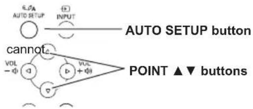
Auto setup function is provided to automatically execute the setting of Auto setup (includes Input search, Auto PC adj. and Auto Keystone functions) in the setting menu by just pressing the AUTO SETUP button on the top control or the AUTO SET button on the remote control. Refer to page 45 for the setting of the Auto setup function.
√Note:
- Auto Keystone corrects vertical distortion does not correct horizontal distortion.
- Auto Keystone cannot work when Ceiling feature is set to On in the Setting menu (pp.35, 43).
- Perfect correction of the image distortion be ensured with the Auto setup function. If the distortion cannot be corrected properly by pressing the AUTO SETUP or AUTO SET button, adjust manually by pressing the KEYSTONE button on the remote control or selecting Keystone in the Screen menu (pp.35, 43).
- Fine sync, Total dots, Horizontal and Vertical of some computers cannot be fully adjusted with the Auto PC Adjustment function. When the image is not provided properly with this operation, manual adjustments are required (pp.30-31).
Keystone Correction
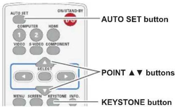
If a projected picture still has keystone distortion after pressing the AUTO SETUP button on the top control or the AUTO SET button on the remote control, correct the image manually as follows:
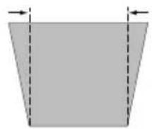
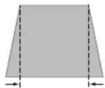
Press the KEYSTONE button on the remote control. The Keystone dialog box appears. Use the Point ▲▼ buttons to correct keystone distortion. The keystone adjustment can be stored (pp.35, 43).
Reduce the upper width with the Point ▲ button.
Reduce the lower width with the Point ▼ button.
Top Control only, it
flowchart
graph TD
    A["AUTO SETUP"] --> B["OUTPUT"]
    C["POINT ▲▼ buttons"] --> D["VOL -"]
    C --> E["VOL +"]
    F["cannot"] --> G["△"]
    F --> H["▽"]
Remote control
text_image
AUTO SET ON/STAND-BY COMPUTER HDMI 1 2 VIDEO S-VIDEO COMPONENT SELECT POINT ▲▼ buttons MENU SCREEN KEYSTONE INFO. KEYSTONE buttonKeystone
•The white arrows indicate that there is no correction.
• A red arrow indicates the direction of correction.
- An arrow disappears at the maximum correction.
- If you press the KEYSTONE button on the remote control once more while the keystone dialog box is being displayed, the keystone adjustment will be canceled.
•The adjustable range is limited depending on the input signal.
Sound Adjustment
Direct Operation
Volume
Press the VOLUME+/- buttons on the top control or on the remote control to adjust the volume. The volume dialog box appears on the screen for a few seconds.
Mute
Press the MUTE button on the remote control to select On to temporarily turn off the sound. To turn the sound back on, press the MUTE button again to select Off or press the VOLUME +/- buttons. The Mute function is also effective for the AUDIO OUT jack.
Menu Operation
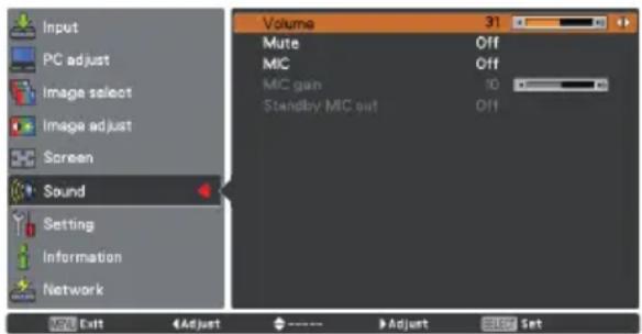
1 Press the MENU button to display the On-Screen Menu. Use the Point ▲▼ buttons to select Sound. Press the Point ▶ button or the SELECT button to access the submenu items.
2 Use the Point ▲▼ buttons to select the desired submenu item and press the SELECT button to access the selected item.
Volume
Press the Point ▶ button to turn up the volume, press the Point ◀ button to turn down the volume.
Mute
Press the SELECT button to switch the mute function On/Off. When the sound is turned off, On is displayed. Press the VOLUME +/- buttons again or adjust MIC gain's volume to turn the sound back on.
MIC
Use the Point ▲▼ buttons to switch the MIC function On/Off, and then press the SELECT button. When On is selected, the synthesis volume (MIC and RCA) is output.
MIC gain
Press the Point ▶ button to turn up the MIC mixing gain, press the Point ◀ button to turn down the MIC mixing gain.
Standby MIC out
When setting the Standby MIC out function to On and in Standby mode status, only MIC input volume can be output.
Top Control
text_image
AUTO SETUP INPUT VOLUME +/- buttons - ↓↓ + ↓↓Remote control
text_image
D.ZOOM VOLUME MUTE IMAGE PIP VOLUME + button MUTE button VOLUME - button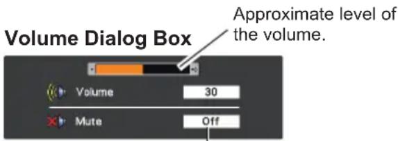
text_image
Volume Dialog Box Approximate level of the volume. Volume 30 Mute OffPress the MUTE button to set the Mute function On or Off. The dialog box disappears after 4 seconds.
Sound Menu
text_image
Input PC adjust Image select Image adjust Screen Sound Setting Information Network Volume 31 Mute Off MIC Off MIC gain 10 Standby MIC out Off OK ExitAUDIO INPUT SELECTION (see pages 14-16)
| AUDIO IN | ||||
| MIC Setup | RCA L/R terminal | COMPUTER AUDIO IN 1 | COMPUTER AUDIO IN 2 (MIC IN) | HDMI (digital audio) |
| MIC Off | Video audio | PC 1 audio | PC 2 audio | HDMI audio |
| MIC On for Video | Video audio | --- MIC --- | ||
| MIC On for PC 1 | --- PC 1 | audio MIC --- | ||
| MIC On for PC 2 | --- PC 2 | audio MIC --- | ||
| MIC on for HDMI | --- | PC 1 audio(*1) | MIC | HDMI audio(*2) |
*1 HDMI setup = Computer 2
*2 HDMI setup = HDMI
√Note:
- When Off is selected in MIC function, the MIC gain and Standby MIC out functions are not available.
- Only when the Standby mode is set to Network, Standby MIC out can be selected.
- If the MIC function is turned on when connecting PC audio to the COMPUTER AUDIO IN 2 (MIC IN), loud sound may be output suddenly depending on the setting value of MIC gain.
Remote control Operation
Using the remote control for some frequently used operations is advisable. Just pressing one of the buttons enables you to make the desired operation quickly without calling up the On-Screen Menu.
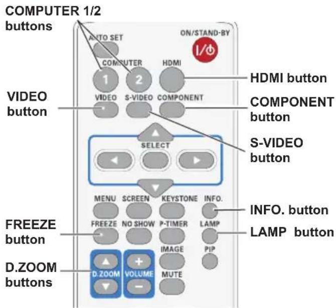
COMPUTER 1/2, HDMI, VIDEO, S-VIDEO and COMPONENT buttons
Press the COMPUTER 1/2, HDMI, VIDEO, S-VIDEO and COMPONENT buttons on the remote control to select the input source. See pages 27, 37 for details.
FREEZE button
Press the FREEZE button on the remote control to freeze the picture on the screen, meanwhile, volume is muted. To cancel the Freeze function, press the FREEZE button again or press any other button.
Fig.1 will appear on the screen while the Freeze function is working.
Fig.1

INFO. button
Display the input source information: Input, H-sync freq., V-sync freq., Screen, Language, Lamp status, Lamp counter, Power management, Key lock, PIN code lock, Remote control and SERIAL NO. and Total power savings. (p.59)
D.ZOOM buttons
Press the D.ZOOM buttons on the remote control to enter to the Digital zoom +/- mode. See page 35 for details.
LAMP button
Press the LAMP button on the remote control to select the lamp mode for changing the brightness on the screen.

Auto......Brightness according to the input signal.
Normal..Normal brightness

Eco 1.....70%-80% of the normal brightness.

Eco 2.....50% of the normal brightness.
Remote control
text_image
COMPUTER 1/2 buttons AUTO SET ON/STAND-BY COMPUTER HDMI VIDEO 1 2 S-VIDEO COMPONENT HDMI button COMPONENT button SELECT S-VIDEO button MENU SCREEN KEYSTONE INFO. FREEZE NO SHOW P-TIMER LAMP D.ZOOM VOLUME MUTE INFO. button LAMP button D.ZOOM BUTTON√Note:
See the next page for the description of other buttons.
NO SHOW button
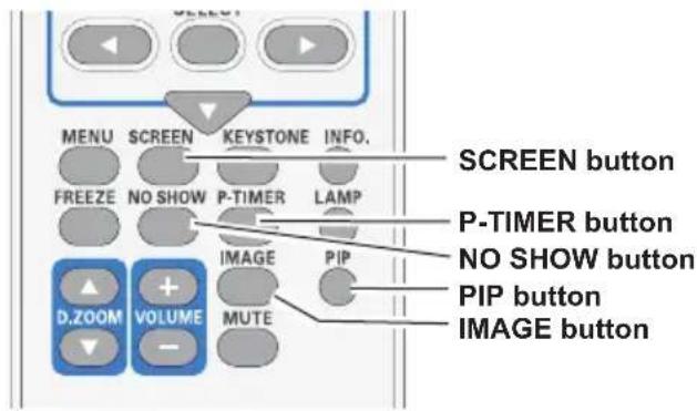
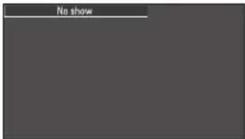
Press the NO SHOW button on the remote control to black out the image. To restore to normal, press the NO SHOW button again or press any button. When the projected image is captured and is set as User in the Logo selection (p. 46), the screen changes each time you press the NO SHOW button as follows.
black out→ the captured image → normal →……
√ Note:
When use the MUTE button to release the No show function, the mute function can not be operated at the same time.
P-TIMER button
Press the P-TIMER button on the remote control to operate the Count up/Count down function. Refer to p.52 for detail of Setting for the P-timer function.
To stop the count time, press the P-TIMER button.
To cancel the P-timer function, press and hold the P-TIMER button.
IMAGE button
Press the IMAGE button on the remote control to select a desired image mode of the screen. See pages 32, 40 for details.
SCREEN button
Select the screen size (See pages 34-35, 42-43 for details).
PIP button
Turn on or turn off the Picture in Picture function.
Remote control
text_image
MENU SCREEN KEYSTONE INFO. FREEZE NO SHOW P-TIMER LAMP D.ZOOM VOLUME IMAGE PIP MUTE SCREEN button P-TIMER button NO SHOW button PIP button IMAGE button√Note:
See the previous page for the description of other buttons.
No show
text_image
No showNo show disappears after 4 seconds.
P-Timer
Input Source Selection (RGB: Computer 1/Computer 2)
Direct Operation
Choose either Computer 1 (RGB) or Computer 2 (RGB) by pressing the COMPUTER 1 or COMPUTER 2 button on the remote control. Or you can press the INPUT button on the top control to choose the desired input source.
Before using these buttons, correct input source should be selected through Menu operation as described below.
Remote control
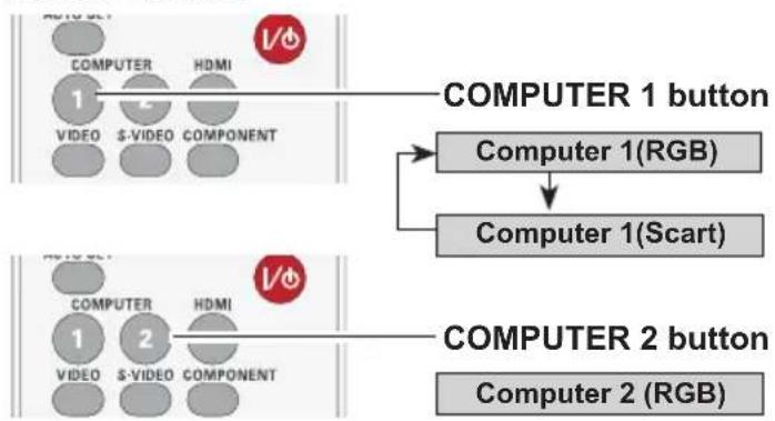
flowchart
graph TD
    A["COMPUTER 1 button"] --> B["Computer 1(RGB)"]
    B --> C["Computer 1(Scart)"]
    D["COMPUTER 2 button"] --> E["Computer 2(RGB)"]
    F["COMPUTER 1 VIDEO S-VIDEO COMPONENT"] --> G["COMPUTER 1 VIDEO"]
    H["COMPUTER 2 VIDEO S-VIDEO COMPONENT"] --> I["COMPUTER 2 VIDEO"]
Top Control
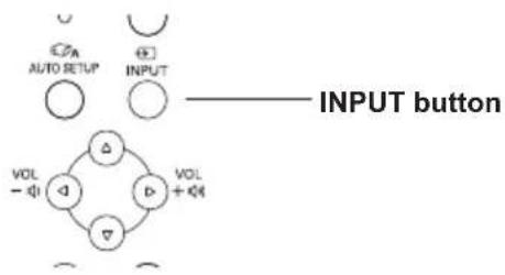
flowchart
graph TD
    A["INPUT button"] --> B["VOL -"]
    A --> C["VOL +"]
    B --> D["△"]
    C --> E["▽"]
    D --> F["○"]
    E --> G["○"]
    H["AUTO SETUP"] --> I["○"]
    J["CPA"] --> K["○"]
    L["⊕"] --> M["○"]
    N["INPUT"] --> O["○"]
    P["VOL"] --> Q["△"]
    R["+"]
Menu Operation
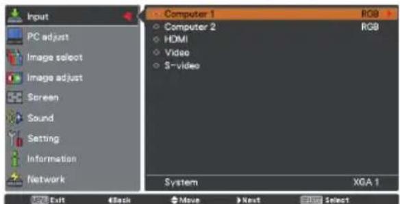
1 Press the MENU button to display the On-Screen Menu. Use the Point ▲▼ buttons to select Input and then press the Point ▶ button or the SELECT button.
2 Use the Point ▲▼ buttons to select Computer 1.
OR
Use the Point ▲▼ buttons to select Computer 2 and then press the SELECT button.
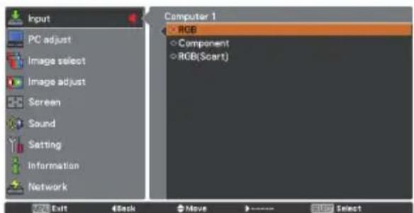
3 When Computer 1 is selected, press the Point ▶ button to access the submenu items. Use the Point ▲▼ buttons to select the RGB input source and then press the SELECT button.
√Note:
When the Input search function is set to On 1 or On 2 in the Auto setup function, the input signal will be searched automatically (p.45).
Input Menu

text_image
Input PC adjust Image select Image adjust Screen Sound Setting Information Network Computer 1 Computer 2 HDMI Video S-video System RGB RGB SVGA 1 Exit Move Next Next
text_image
Input PC adjust Image select Image adjust Screen Sound Setting Information Network Computer 1 Computer 2 HDMI Video S-video System XGA 1 Exit Back Move Next SelectComputer 1
text_image
Input PC adjust Image select Image adjust Screen Sound Setting Information Network Computer 1 RGB Component RGB(Scart) Exit Back Move SelectComputer System Selection
This projector automatically tunes to various types of computers with its Multi-scan system and Auto PC Adjustment. If a computer is selected as a signal source, this projector automatically detects the signal format and tunes to project a proper image without any additional settings. (Signal formats provided in this projector are shown on page 71-72.)
One of the following messages may appear when:
Auto
When the projector cannot recognize the connected signal conforming to the provided PC systems, Auto is displayed on the System Menu box and the Auto PC Adjustment function works to display proper images. If the image is not projected properly, a manual adjustment is required (pp. 30-31).
...
There is no signal input from the computer. Check the connection between your computer and the projector. (See “Troubleshooting” on pp. 65-67)
Mode 1
The preset system is manually adjusted in the PC adjust Menu. The adjusted data can be stored in Mode 1-10 (pp. 30-31).
SVGA 1
PC Systems provided in this projector is chosen. The projector chooses a proper system provided in the projector and displays it.
*Mode 1 and SVGA 1 are examples.
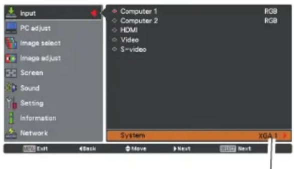
PC System Menu
text_image
Input PC adjust Image select Image adjust Screen Sound Setting Information Network Computer 1 Computer 2 HDMI Video S-video RGB RGB System XGA 1 Exit Back Move Next NextSelected system in the PC System Menu is displayed.
Selecting Computer System Manually
PC system can also be selected manually.
1 Press the MENU button to display the On-Screen Menu. Use the Point ▲▼ buttons to select Input and then press the Point ▶ button or the SELECT button.
2 Use the Point ▲▼ buttons to select System and then press the Point ▶ button or the SELECT button.
3 Use the Point ▲▼ buttons to select the desired system and then press the SELECT button.
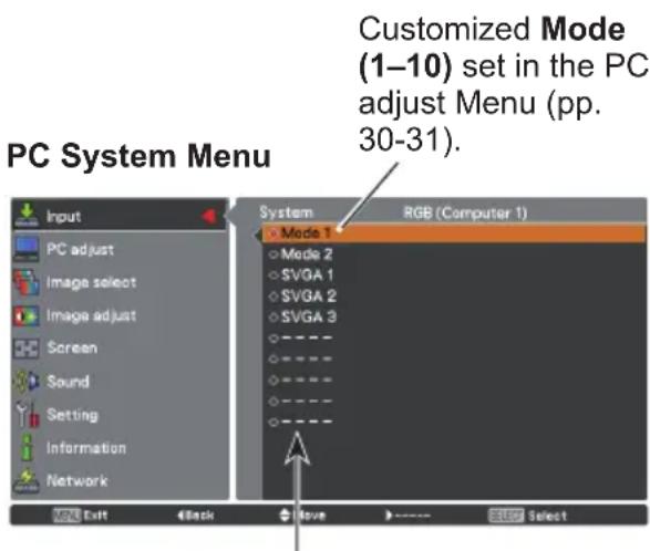
text_image
Customized Mode (1–10) set in the PC adjust Menu (pp. 30-31). PC System Menu Input PC adjust Image select Image adjust Screen Sound Setting Information Network System Mode 1 Mode 2 SVGA 1 SVGA 2 SVGA 3 RGB (Computer 1) VOUT Back Save SelectSystems in this dialog box can be selected.
Auto PC Adjustment
Auto PC Adjustment function is provided to automatically adjust Fine sync, Total dots, Horizontal and Vertical to conform to your computer.
Menu Operation
Auto PC adj.
1 Press the MENU button to display the On-Screen Menu. Use the Point ▲▼ buttons to select PC adjust and then press the Point ▶ button or the SELECT button.
2 Use the Point ▲▼ buttons to select Auto PC adj. and then press the SELECT button.
To store adjustment parameters
The adjusted parameters from the Auto PC Adjustment can be stored in the projector. Once the parameters are stored, the setting can be done just by selecting a Mode (1–10) in the PC System Menu (p.28). See also "Store" on page 31.
PC adjust Menu
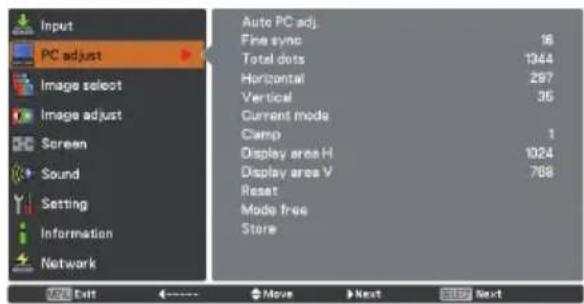
text_image
Input PC adjust Image select Image adjust Screen Sound Setting Information Network Auto PC adj. Fine sync 16 Total dots 1344 Horizontal 287 Vertical 35 Current mode Clamp 1 Display area H 1024 Display area V 768 Reset Mode free Store OK Exit <----> Move Next Help Next
Use Point ▲▼ buttons to select Auto PC adj. and press the SELECT button. Please wait... appears while the Auto PC adjustment is in process.
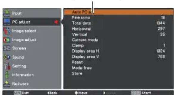
text_image
Input PC adjust Image select Image adjust Screen Sound Setting Information Network Auto PC as Fine sync 16 Total dots 1344 Horizontal 297 Vertical 35 Current mode Clamp 1 Display area H 1024 Display area V 768 Reset Mode free Store Exit Back Move Start√Note:
- Fine sync, Total dots, Horizontal and Vertical of some computers cannot be fully adjusted with the Auto PC Adjustment function. When the image is not provided properly with this operation, manual adjustments are required (pp. 30-31).
- The Auto PC Adjustment cannot be operated when 480i, 575i, 480p, 575p, 720p, 1035i or 1080i is selected in the PC System Menu (p. 28), or when the signal is coming from the HDMI terminal.
Manual PC Adjustment
Some computers employ special signal formats which may not be tuned by Multi-scan system of this projector. Manual PC Adjustment enables you to precisely adjust several parameters to match those signal formats. The projector has 10 independent memory areas to store those parameters manually adjusted. It allows you to recall the setting for a specific computer.
1 Press the MENU button to display the On-Screen Menu. Use the Point ▲▼ buttons to select PC adjust and then press the Point ▶ button or the SELECT button.
2 Use the Point ▲▼ buttons to select the desired item and then press the SELECT button to display the adjustment dialog box. Use the Point ◀▶ buttons to adjust the setting value.
Fine sync
Use the Point ◀▶ buttons to adjust the value, eliminating a flicker from the image displayed (from 0 to 31).
Total dots
Use the Point ◀▶ buttons to adjust the number of total dots in one horizontal period to match your PC image.
Horizontal
Use the Point ◀▶ buttons to adjust the horizontal picture position.
Vertical
Use the Point ◀▶ buttons to adjust the vertical picture position.
Current mode
Press the SELECT button to show H-sync freq. and V-sync freq. of the connected computer.
Clamp
Use the Point ◀▶ buttons to adjust the clamp level. When the image has dark bars, try this adjustment.
Display area H
Use the Point ◀▶ buttons to adjust the horizontal area displayed by this projector.
Display area V
Use the Point ◀▶ buttons to adjust the vertical area displayed by this projector.
PC adjust Menu
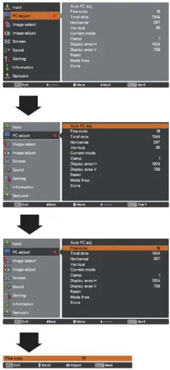
flowchart
graph TD
    A["Input PC adjust"] --> B["Image select"]
    B --> C["Image adjust"]
    C --> D["Screen"]
    D --> E["Sound"]
    E --> F["Setting"]
    F --> G["Information"]
    G --> H["Network"]

    I["Auto PC adj."] --> J["Fine sync: 16"]
    J --> K["Total dots: 1344"]
    K --> L["Horizontal: 297"]
    L --> M["Vertical: 35"]
    M --> N["Current mode: Clamp: 1"]
    N --> O["Display area H: 1024"]
    O --> P["Display area V: 788"]
    P --> Q["Reset: Mode free: Store"]

    R["Input PC adjust"] --> S["Image select"]
    S --> T["Image adjust"]
    T --> U["Screen"]
    U --> V["Sound"]
    V --> W["Setting"]
    W --> X["Information"]
    X --> Y["Network"]

    Z["Auto PC adj."] --> AA["Fine sync: 16"]
    AA --> AB["Total dots: 1344"]
    AB --> AC["Horizontal: 297"]
    AC --> AD["Vertical: 35"]
    AD --> AE["Current mode: Clamp: 1"]
    AE --> AF["Display area H: 1024"]
    AF --> AG["Display area V: 788"]
    AG --> AH["Reset: Mode free: Store"]

    AI["Input PC adjust"] --> AJ["Image select"]
    AJ --> AK["Image adjust"]
    AK --> AL["Screen"]
    AL --> AM["Sound"]
    AM --> AN["Setting"]
    AN --> AO["Information"]
    AO --> AP["Network"]

    AQ["Auto PC adj."] --> AR["Fine sync: 16"]
    AR --> AS["Total dots: 1344"]
    AS --> AT["Horizontal: 297"]
    AT --> AU["Vertical: Current mode: Clamp: 1"]
    AU --> AV["Display area H: 1024"]
    AV --> AW["Display area V: 788"]
    AW --> AX["Reset: Mode free: Store"]

    AY["Fine sync"] --> AZ["Exit"] --> BA["Scroll"] --> BB["Adjust"] --> BC["Back"]
Reset
To reset the adjusted data, select Reset and press the SELECT button. A confirmation box appears and then select Yes. All adjustments will return to their previous figures.
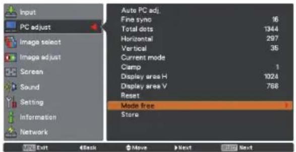
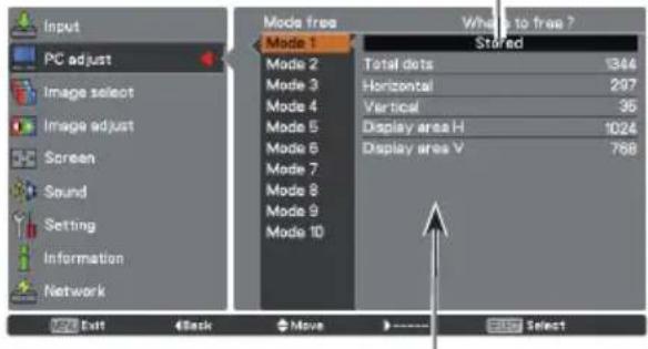
Mode free
To clear the stored data, select Mode free and then press the Point ▶ button or the SELECT button. Move the highlight to the Mode that you want to clear and then press the SELECT button.
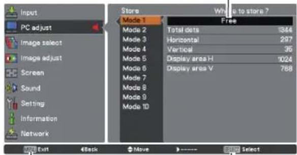
Store
To store the adjusted data, select Store and then press the Point ▶ button or the SELECT button. Move the highlight to one of the Mode 1 to 10 in which you want to store, and then press the SELECT button.
Mode free
text_image
Input PC adjust Image select Image adjust Screen Sound Setting Information Network Auto PC adj. Fine syno 16 Total dots 1344 Horizontal 297 Vertical 35 Current mode Clamp 1 Display area H 1024 Display area V 768 Reset Mode free Store Exit Back Move Next Next
This Mode has stored parameters.
text_image
Input PC adjust Image select Image adjust Screen Sound Setting Information Network Mode free Mode 1 Total dots 346 Horizontal 297 Vertical 35 Display area H 1024 Display area V 768 What is to free ? Stored Exit Back Move SelectValues of Total dots, Horizontal, Vertical, Display area H, and Display area V.
Store
text_image
Input PC adjust Image select Image adjust Screen Sound Setting Information Network Store Mode 1 Total dots 344 Mode 2 Horizontal 297 Mode 3 Vertical 36 Mode 4 Display area H 1024 Mode 5 Display area V 768 Mode 6 Mode 7 Mode 8 Mode 9 Mode 10 White to store ? Free 177 Exit Back Move SelectPress the MENU button to close this dialog box.
Press the SELECT button to store the data.
√Note:
- Display area (H/V) cannot be selected when 480i, 575i, 480p, 575p, 720p, 1035i or 1080i is selected in the PC System Menu (p.28).
- When input computer signal to the projector, PC adjust will become available.
Image Mode Selection
Direct Operation
Select the desired image mode among Dynamic, Standard, Real, Cinema, Blackboard (Green), Colorboard, Image 1, Image 2, Image 3 and Image 4 by pressing the IMAGE button on the remote control.
Menu Operation
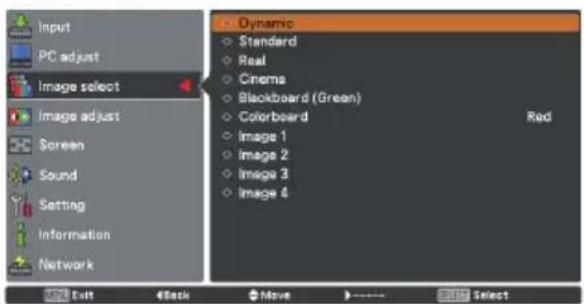
1 Press the MENU button to display the On-Screen Menu. Use the Point ▲▼ buttons to select Image select and then press the Point ▶ button or the SELECT button.
2 Use the Point ▲▼ buttons to select the desired item and then press the SELECT button.
Dynamic
For viewing pictures in a bright room.
Standard
Normal picture mode preset on the projector.
Real
Picture mode with improved halftone for graphics.
Cinema
Picture mode adjusted with fine tone.
Blackboard (Green)
For the image projected on a blackboard. This mode helps enhance the image projected on a blackboard. This is mainly effective on a green colored board, not truly effective on a black colored board.
Colorboard
At the time of simple projection on the colored wall, you can get the close color image to the color image projected on a white screen by selecting the similar color to the wall color from the preset four colors.
Image 1-4
For viewing with the user preset image mode in the Image Adjust Menu (see page 33).
Remote control
text_image
MENU SCREEN KEYSTONE INFO. FREEZE NO SHOW P-TIMER LAMP D.ZOOM VOLUME IMAGE PIP M TEIMAGE button
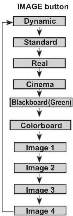
flowchart
graph TD
    A["IMAGE button"] --> B["Dynamic"]
    B --> C["Standard"]
    C --> D["Real"]
    D --> E["Cinema"]
    E --> F["Blackboard(Green)"]
    F --> G["Colorboard"]
    G --> H["Image 1"]
    H --> I["Image 2"]
    I --> J["Image 3"]
    J --> K["Image 4"]
Image select Menu
text_image
Input PC adjust Image select Image adjust Screen Sound Setting Information Network Dynamic Standard Real Cinema Blackboard (Green) Colorboard Red Image 1 Image 2 Image 3 Image 4 OUT Exit Move Next Next
text_image
Input PC adjust Image select Image adjust Screen Sound Setting Information Network Dynamic Standard Real Cinema Blackboard (Green) Colorboard Image 1 Image 2 Image 3 Image 4 Red Exit Back Move SelectImage Adjustment
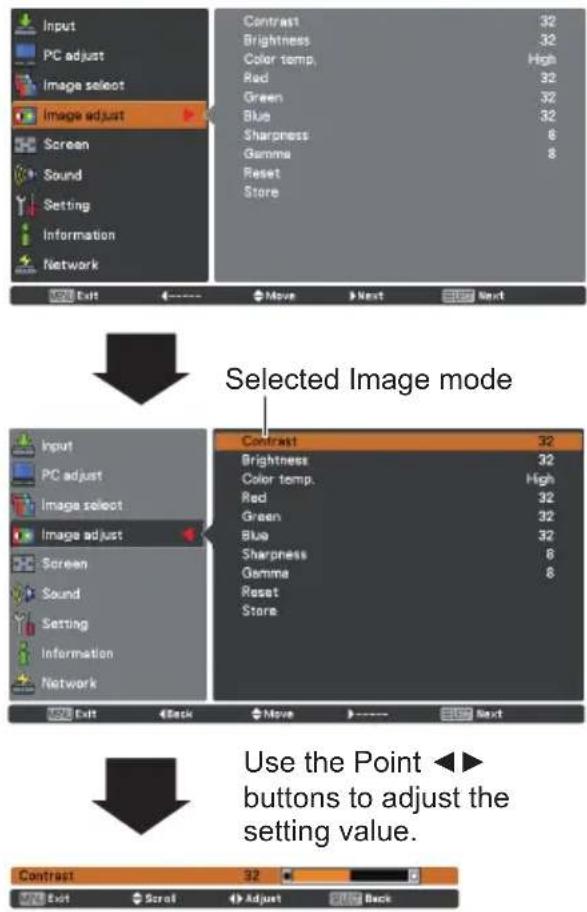
1 Press the MENU button to display the On-Screen Menu. Use the Point ▲▼ buttons to select Image adjust and then press the Point ▶ button or the SELECT button.
2 Use the Point ▲▼ buttons to select the desired item and then press the SELECT button to display the adjustment dialog box. Use the Point ◀▶ buttons to adjust the setting value.
Contrast
Press the Point ◀ button to decrease the contrast, press the Point ▶ button to increase the contrast (from 0 to 63).
Brightness
Press the Point ◀ button to decrease the brightness, press the Point ▶ button to increase the brightness (from 0 to 63).
Color temp.
Use the Point ◀▶ buttons to select the desired Color temp. level (XLow, Low, Mid, or High).
White balance (Red / Green / Blue)
Press the Point ▶ button to lighten R/G/B tone, press the Point ▶ button to deepen R/G/B tone (from 0 to 63).
Sharpness
Press the Point ◀ button to decrease the sharpness of the image, press the Point ▶ button to increase the sharpness of the image (from 0 to 15).
Gamma
Use the Point ◀▶ buttons to adjust the gamma value to obtain a better balance of contrast (from 0 to 15).
Reset
To reset the adjusted data, select Reset and press the SELECT button. A confirmation box appears and then select Yes. All adjustments will return to their previous figures.
Store
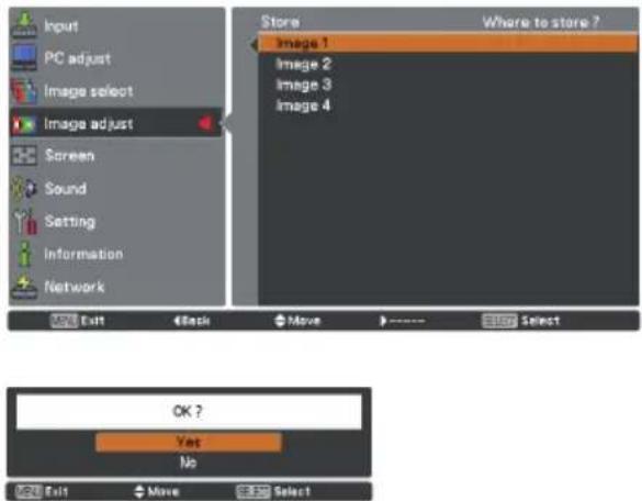
To store the adjusted data, select Store and press the Point ▶ or the SELECT button. Use the Point ▲▼ buttons to select one from Image 1 to Image 4 and press the SELECT button. A confirmation box appears and then select Yes. Stored data can be called up by selecting an Image (1-4) in the Image Mode Selection on page 32.
Image Adjust Menu
text_image
Input PC adjust Image select Image adjust Screen Sound Setting Information Network Contrast 32 Brightness 32 Color temp. High Red 32 Green 32 Blue 32 Sharpness 6 Gamma 8 Reset Store Move Next Stop Next Selected Image mode Input PC adjust Image select Image adjust Screen Sound Setting Information Network Contrast 32 Brightness 32 Color temp. High Red 32 Green 32 Blue 32 Sharpness 6 Gamma 8 Reset Store Use the Point buttons to adjust the setting value. Contrast 32 Exit Scroll Adjust BackStore
text_image
Input PC adjust Image select Image adjust Screen Sound Setting Information Network Store Where to store ? Image 1 Image 2 Image 3 Image 4 Exit Back Move - Select OK ? Yes No Exit Move SelectA confirmation box appears and then select Yes.
√Note:
- When White balance Red, Green or Blue is adjusted, Color temp. will change to User.
- When Blackboard(Green) or Colorboard is selected in Image select, Color temp. will change to Blackboard or Colorboard.
Screen Setting
This projector has the picture screen resize function, which enables you to customize the image size.
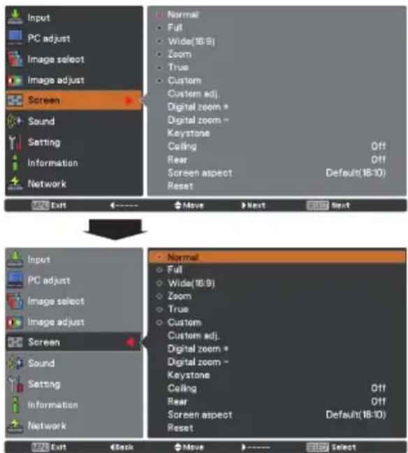
1 Press the MENU button to display the On-Screen Menu. Use the Point ▲▼ buttons to select Screen and then press the Point ▶ button or the SELECT button.
2 Use the Point ▲▼ buttons to select the desired item and then press the SELECT button.
Normal
Provide the image to fit the screen size.
Full
Provide the full screen image.
Wide (16:9)
Provide the image at the 16:9 wide screen ratio.
Zoom
Scale the image proportionally to fit the entire screen. Either side of image may go over the screen.
True
Provide the image in its original size. When the original image size is larger or smaller than the screen size (1280 x 800), the projector enters to the panning mode automatically. Use the Point ▲▼◀▶ buttons to pan the image. When adjusted, the arrows will turn blue. When reached to the correction limits, the arrows will disappear.
Custom
Provide the last stored aspect screen image.
Custom adj.
Adjust the screen scale and position manually with this function. Press the Point ▶ button at Custom adj. and the Custom adjustment menu is displayed on the screen, you can use the Point ▲▼ buttons to choose the item you want to adjust.
Scale H/V ..... Adjust the Horizontal/Vertical screen scale. H&V ..... When set to On, the aspect ratio is fixed. The Scale V appears dimmed and becomes unavailable. Adjust Scale H, then the screen scale is automatically modified based on the aspect ratio.
Position H/V .. Adjust the Horizontal/Vertical screen position.
Common ..... Save the adjusted scale or position to all the inputs. Press the SELECT button at Common to display a confirmation box. To save the scale or position, press the SELECT button at Yes. When Custom is selected, the saved scale or position is used.
Reset ...... Reset the all adjusted values. Press the SELECT button at Reset to display a confirmation box. To reset, press the SELECT button at Yes.
Screen Menu
text_image
Input PC adjust Image select Image adjust Screen Sound Setting Information Network Normal Full Wide(18:9) Zoom True Custom Custom adj. Digital zoom * Digital zoom - Keystone Ceiling Off Rear Off Screen aspect Default(18:10) Reset Exit Move Next Next Input PC adjust Image select Image adjust Screen Sound Setting Information Network Normal Full Wide(18:9) Zoom True Custom Custom adj. Digital zoom * Digital zoom - Keystone Ceiling Off Rear Off Screen aspect Default(18:10) Reset Exit Back Move Select√ Note:
- This projector cannot display any resolution higher than 1920 x 1200. If your computer's screen resolution is higher than it, reset the resolution to the lower before connecting to the projector.
- The image data in other than 1280 x is modified to fit the screen size in initial mode.
- True and Digital zoom +/- are disabled and cannot be displayed when 480i, 575i, 480p, 575p, 720p, 1035i or 1080i is selected in the PC System Menu (p. 28).
- When True is selected in the Screen menu, Digital zoom +/- can not be selected.
Custom adj.
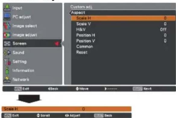
text_image
Input PC adjust Image select Image adjust Screen Sound Setting Information Network Custom adj. Aspect Scale H 0 Scale V 0 H&V Off Position H 0 Position V 0 Common Reset Exit Back Move Next Scale H 0 Exit Scroll Adjust Back√ Note:
- When no signal is detected, Normal is set automatically.
• The adjustable range for Scale H/V and Position H/V is limited depending on the input signal.
Digital zoom +
Select Digital zoom +. The On-Screen Menu disappears and D. zoom + appears. Press the SELECT button to expand the image size. Use the Point ▲▼◀▶ buttons to pan the image. The Panning function can work only when the image is larger than the screen size. A projected image can be also expanded by pressing the D.ZOOM ▲ or the SELECT button.
Digital zoom –
Select Digital zoom -. The On-Screen Menu disappears and D. zoom - appears. Press the SELECT button to compress image size. The projected image can be also compressed by pressing the D.ZOOM ▼ or the SELECT button.
To exit the Digital zoom +/- mode, press any button except the D.ZOOM ▲▼, SELECT and Point buttons.
To return to the previous screen size, select a screen size from the Screen Size Adjustment Menu or select an input source from the Input Source Selection Menu (see page 27) again, or adjust the screen size with the D.ZOOM ▲▼ buttons.
Keystone
This function is used to adjust keystone distortion of the projected image. Use the Point ▲▼ buttons to choose the item you want to adjust.
Kéystone
To correct keystone distortion, press the SELECT button.
Keystone appears on the screen. Use the Point ▲▼ buttons to correct keystone distortion (p.23).
Store
To store or reset the keystone correction, press the Point ▶ button.
Store .... Keep the keystone correction even when the AC power cord is unplugged.
Reset ...... Release the keystone correction when the AC power cord is unplugged.
Ceiling
When this function is set to On, the picture will be top/ bottom and left/right reversed. This function is used to project the image from a ceiling-mounted projector.
Rear
When this function is set to On, the picture will be left/right reversed. This function is used to project the image from rear of the screen.
Screen aspect
This function is used to project the image to a 4:3 or 16:9 projection screen.
Default (16:10) ....16:10 is the aspect of the LCD panel. The original Screen Menu is available.
16:9 ..... Set to a 16:9 projection screen.
4:3 .....Set to a 4:3 projection screen.
Reset
To reset the adjusted data, select Reset and press the SELECT button. A confirmation box appears and then select Yes. All adjustments will return to their previous figures.
Remote control
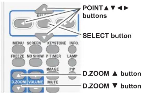
text_image
POINT ▲ ▼ ◀◀▶ buttons SELECT button MENU SCREEN KEYSTONE INFO. FREEZE NO SHOW P-TIMER LAMP IMAGE PIP D.ZOOM ▲ button D.ZOOM VOLUME MUTE D.ZOOM ▼ buttonKeystone
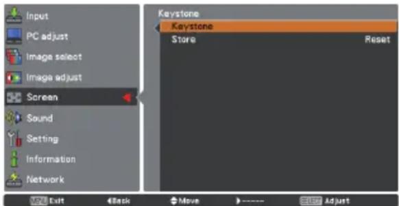
text_image
Input PC adjust Image select Image adjust Screen Sound Setting Information Network Keystone Keystone Store Reset Exit Back Move - - Set AdjustCeiling
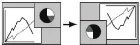
flowchart
graph LR
    A["Line Graph"] --> B["Circle Node"]
    B --> C["Line Chart"]
Rear
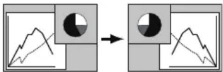
flowchart
graph LR
    A["Grid with pie chart"] --> B["Single Pie Chart"]
√Note:
- The minimum compression ratio is limited depending on the input signal, when the Keystone function is working or when the custom is selected for the screen size.
- True and Digital zoom +/- are disabled and cannot be displayed when 480i, 575i, 480p 575p, 720p,1035i or 1080i is selected in the PC System Menu (p.28).
- Digital zoom +/- cannot be selected when True is selected.
- The minimum compression ratio is limited at Normal screen size.
- When the 16:9 function is selected on Screen aspect menu, Wide (16:9) is not available in the PC and AV screen (pp.34, 47).
Input Source Selection (Video, S-video)
Direct Operation
Choose VIDEO or S-VIDEO by pressing the INPUT button on the top control, or the VIDEO or the S-VIDEO button on the remote control. Before using these buttons, correct input source should be selected through menu operation as described below.
Top Control
flowchart
graph TD
    A["INPUT button"] --> B["VOL -"]
    A --> C["VOL +"]
    A --> D["△"]
    A --> E["▽"]
    A --> F["⊕"]
    A --> G["⊕"]
    A --> H["⊕"]
    A --> I["⊕"]
    A --> J["⊕"]
    A --> K["⊕"]
    A --> L["⊕"]
    A --> M["⊕"]
    A --> N["⊕"]
    A --> O["⊕"]
    A --> P["⊕"]
    A --> Q["⊕"]
    A --> R["⊕"]
    A --> S["⊕"]
    A --> T["⊕"]
    A --> U["⊕"]
    A --> V["⊕"]
    A --> W["⊕"]
    A --> X["⊕"]
    A --> Y["⊕"]
    A --> Z["⊕"]
Remote control
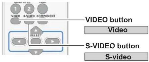
text_image
VIDEO button Video S-VIDEO button S-videoMenu Operation
1 Press the MENU button to display the On-Screen Menu. Use the Point ▲▼ buttons to select Input and then press the Point ▶ button or the SELECT button.
2 Use the Point ▲▼ buttons to select Video or S-video, and then press the SELECT button.
Video
When video input signal is connected to the Video jack, select Video.
S-video
When video input signal is connected to the S-video jack, select S-video.
Video
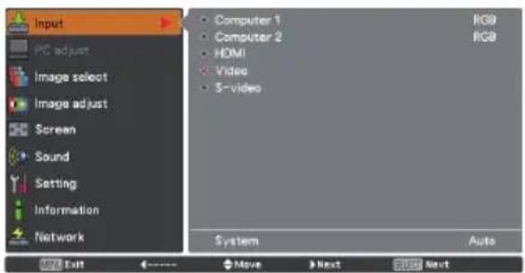
text_image
Input PC adjust Image select Image adjust Screen Sound Setting Information Network Computer 1 Computer 2 HDMI Video 5-video System Auto RGB RGB System Exit Move Next Stop Next√Note:
When the Input search function is set to On 1 or On 2 in the Auto setup function, the input signal will be searched automatically (p.45).
Input Source Selection (Component, Scart, HDMI)
Direct Operation
Choose Computer 1(Component) or Computer 1 RGB (Scart) by pressing the COMPONENT or the COMPUTER 1 button on the remote control. Choose HDMI by pressing the HDMI button on the remote control or you can press the INPUT button on the top control to choose the desired input source.
Before using these buttons, correct input source should be selected through Menu operation as described below.
Remote control
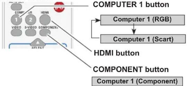
flowchart
graph TD
    A["COMP R"] --> B["1"]
    C["2"] --> D["VIDEO"]
    E["HDMI"] --> F["S-VIDEO COMPONENT"]
    G["SEI PCT"] --> H["COMPONENT BUTTON"]
    I["COMPUTER 1 button"] --> J["Computer 1 (RGB)"]
    K["COMPUTER 1 (Scart)"] --> L["Computer 1 (Scart)"]
Top Control
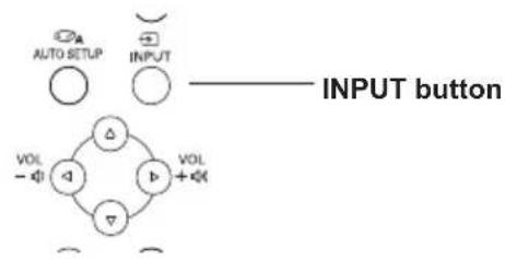
flowchart
graph TD
    A["AUTO SETUP"] --> B["△"]
    C["INPUT"] --> D["▽"]
    E["VOL - φ"] --> F["△"]
    G["VOL + φ"] --> H["▽"]
    I["INPUT button"] --> J["△"]
    K["○"] --> L["○"]
Menu Operation
1 Press the MENU button to display the On-Screen Menu. Use the Point ▲▼ buttons to select Input and then press the Point ▶ button or the SELECT button.
2 Use the Point ▲▼ buttons to select Computer 1 and then press the Point ▶ button.
3 Use the Point ▲▼ buttons to select Component or RGB(Scart) and then press the SELECT button.
Component
When the input source is coming from video equipment connected to the COMPUTER IN 1/COMPONENT IN terminal with a COMPONENT-VGA Cable, select Component.
RGB (Scart)
When the input source is coming from video equipment connected to the COMPUTER IN 1/COMPONENT IN terminal with a Scart-VGA Cable, select RGB (Scart).
HDMI
When video input signal is connected to the HDMI jack, select HDMI.
√Note:
When the Input search function is set to On 1 or On 2, the input signal will be searched automatically (p.45).
Input Menu
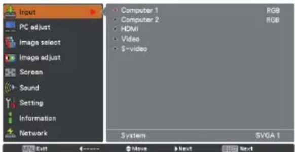
text_image
Input PC adjust Image select Image adjust Screen Sound Setting Information Network Computer 1 Computer 2 HDMI Video S-video RGB RGB System SVGA 1 USB Exit Move Next Next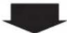
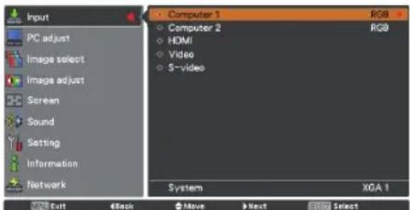
text_image
Input PC adjust Image select Image adjust Screen Sound Setting Information Network Computer 1 Computer 2 HDMI Video S-video System XGA 1 Exit Back Move Next Select
Press the Point ▲▼ buttons to select Component or RGB (Scart).
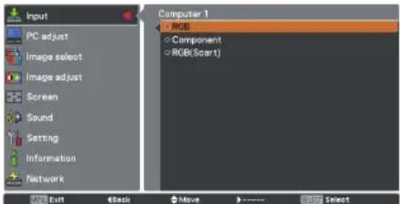
text_image
Input PC adjust Image select Image adjust Screen Sound Setting Information Network Computer 1 RGB Component RGB(Scart) VOLT Exit Back Move SelectVideo System Selection
1 Press the MENU button to display the On-Screen Menu. Use the Point ▲▼ buttons to select Input and then press the Point ▶ button or the SELECT button.
2 Use the Point ▲▼ buttons to select Video, S-video or Computer 1(Component) and then press the SELECT button.
3 Use the Point ▲▼ buttons to select System and then press the Point ▶ button or the SELECT button. Use the Point ▲▼ buttons to select the desired system and then press the SELECT button.
Video or S-video
Auto
The projector automatically detects an incoming video system, and adjusts itself to optimize its performance. When Video System is PAL-M or PAL-N, select the system manually.
PAL/SECAM/NTSC/NTSC4.43/PAL-M/PAL-N
If the projector cannot reproduce proper video image, select a specific broadcast signal format from among PAL, SECAM, NTSC, NTSC 4.43, PAL-M and PAL-N.
Component
Auto
The projector automatically detects an incoming video signal, and adjusts itself to optimize its performance.
COMPONENT VIDEO SIGNAL FORMAT
If the projector cannot reproduce proper video image, select a specific component video signal format from among 480i, 575i, 480p, 575p, 720p, 1035i and 1080i.
√Note:
The AV System Menu cannot be selected when selecting RGB(Scart) or HDMI.
AV System Menu (Video or S-video)
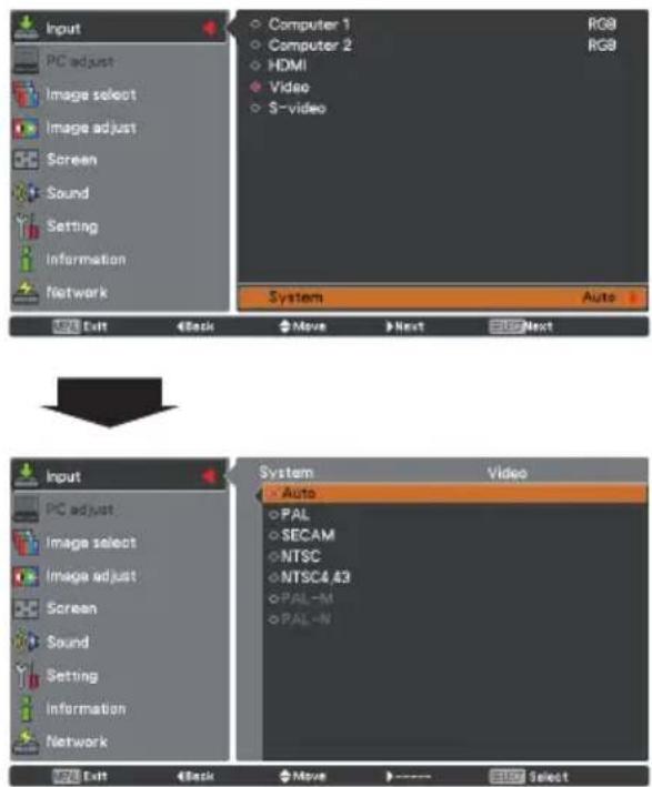
text_image
Input PC adjust Image select Image adjust Screen Sound Setting Information Network Computer 1 Computer 2 HDMI Video S-video System Auto Back Move Next Next System Auto PAL SECAM NTSC NTSC4.43 PAL-M PAL-N System Video Input PC adjust Image select Image adjust Screen Sound Setting Information Network System Auto PAL SECAM NTSC NTSC4.43 PAL-M PAL-N System Auto Back Move SelectAV System Menu (Component)
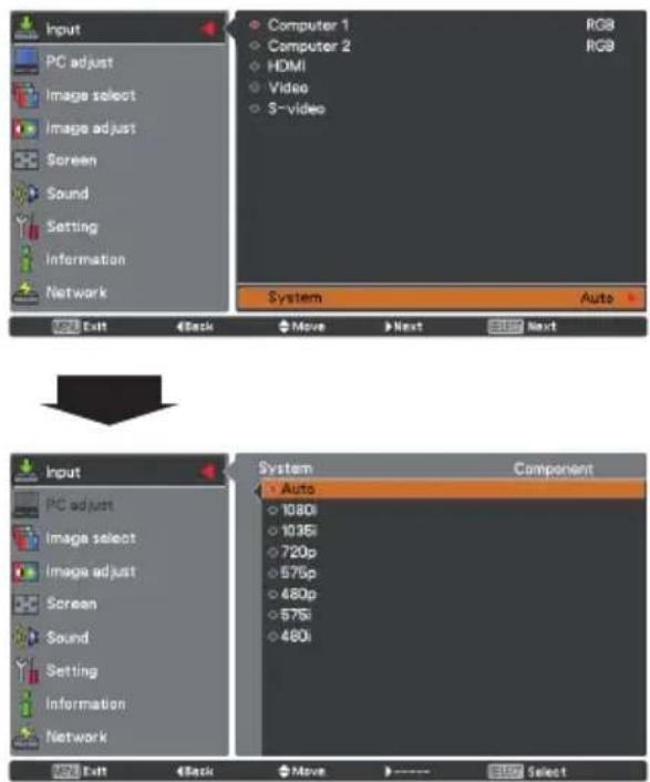
text_image
Input PC adjust Image select Image adjust Screen Sound Setting Information Network Computer 1 Computer 2 HDMI Video S-video System Auto Exit Back Move Next Next Input PC adjust Image select Image adjust Screen Sound Setting Information Network System Auto 1080i 1036i 720p 575p 480p 575i 480i Component Exit Back Move Next SelectImage Mode Selection
Direct Operation
Select the desired image mode among Dynamic, Standard, Real, Cinema, Blackboard (Green), Colorboard, Image 1, Image 2, Image 3 and Image 4 by pressing the IMAGE button on the remote control.
Menu Operation
1 Press the MENU button to display the On-Screen Menu. Use the Point ▲▼ buttons to select Image select and then press the Point ▶ button or the SELECT button.
2 Use the Point ▲▼ buttons to select the desired item and then press the SELECT button.
Dynamic
For viewing pictures in a bright room.
Standard
Normal picture mode preset on the projector.
Real
Picture mode with improved halftone for graphics.
Cinema
Picture mode adjusted with fine tone.
Blackboard (Green)
For the image projected on a blackboard. This mode helps enhance the image projected on a blackboard. This is mainly effective on a green colored board, not truly effective on a black colored board.
Colorboard
At the time of simple projection on the colored wall, you can get the close color image to the color image projected on a white screen by selecting the similar color to the wall color from the preset four colors.
Image 1-4
For viewing with the user preset image mode in the Image Adjust Menu (p. 41).
Remote control
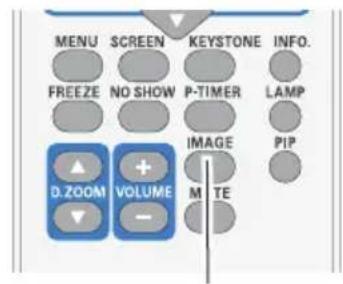
text_image
MENU SCREEN KEYSTONE INFO. FREEZE NO SHOW P-TIMER LAMP IMAGE PIP D.ZOOM VOLUME M I TEIMAGE button
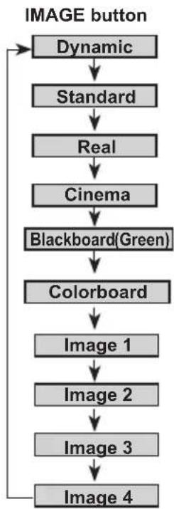
flowchart
graph TD
    A["IMAGE button"] --> B["Dynamic"]
    B --> C["Standard"]
    C --> D["Real"]
    D --> E["Cinema"]
    E --> F["Blackboard(Green)"]
    F --> G["Colorboard"]
    G --> H["Image 1"]
    H --> I["Image 2"]
    I --> J["Image 3"]
    J --> K["Image 4"]
Image select Menu
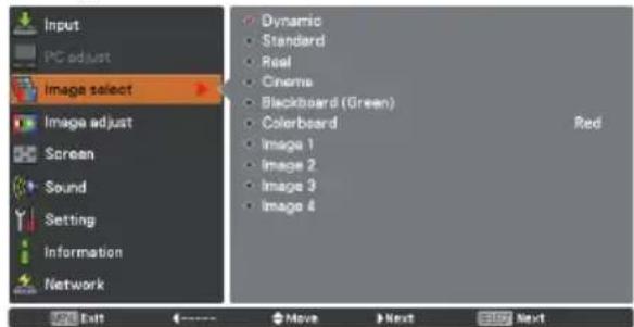
text_image
Input PC adjust Image select Image adjust Screen Sound Setting Information Network Dynamic Standard Real Cinema Blackboard (Green) Colorboard Red Image 1 Image 2 Image 3 Image 4 Exit Move Next Next Next
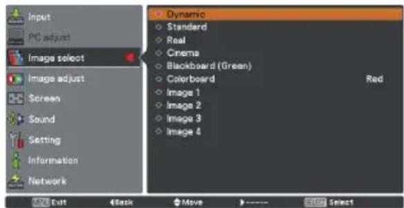
text_image
Input PC adjust Image select Image adjust Screen Sound Setting Information Network Dynamic Standard Real Cinema Blackboard (Green) Colorboard Image 1 Image 2 Image 3 Image 4 Red OK Exit 4 Back Move ---- STOP SelectImage Adjustment
1 Press the MENU button to display the On-Screen Menu. Use the Point ▲▼ buttons to select Image adjust and then press the SELECT button.
2 Use the Point ▲▼ buttons to select the desired item and then press the SELECT button to display the adjustment dialog box. Use the Point ◀▶ buttons to adjust the setting value.
Contrast
Press the Point ◀ button to decrease the contrast, press the Point ▶ button to increase the contrast (from 0 to 63).
Brightness
Press the Point ◀ button to decrease the brightness, press the Point ▶ button to increase the brightness (from 0 to 63).
Color
Press the Point ◀ button decrease the intensity of the color, press the Point ▶ button increase the intensity of the color (from 0 to 63).
Tint
Press the Point ◀▶ buttons to adjust the tint value to get a proper color balance (from 0 to 63).
Color temp.
Use the Point ◀▶ buttons to select the desired Color temp. level (XLow, Low, Mid or High).
White balance (Red / Green / Blue)
Press the Point ◀ button to lighten R/G/B tone, press the Point ▶ button to deepen R/G/B tone (from 0 to 63).
Sharpness
Press the Point ◀ button to decrease the sharpness of the image, press the Point ▶ button to increase the sharpness of the image (from 0 to 15).
Gamma
Use the Point ◀▶ buttons to adjust the gamma value to obtain a better balance of contrast (from 0 to 15).
√Note:
- When the White balance Red, Green or Blue is adjusted, the Color temp. will change to User.
- Tint cannot be selected when the video system is PAL, SECAM, PAL-M or PAL-N (p. 38).
- When Blackboard (Green) or Colorboard is selected in Image select, Color temp. will change to Blackboard or Colorboard.
Image Adjust Menu
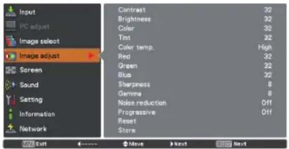
text_image
Input PC adjust Image select Image adjust Screen Sound Setting Information Network Contrast 32 Brightness 32 Color 32 Tint 32 Color temp. High Red 32 Green 32 Blue 32 Sharpness 8 Gamma 8 Noise reduction Off Progressive Off Reset Store 372 Exit <----> Move > Next Stop Next
Selected Image mode
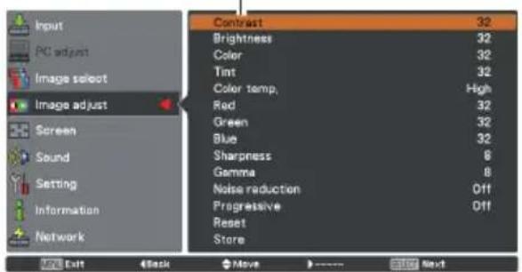
text_image
Input PC adjust Image select Image adjust Screen Sound Setting Information Network contrast 32 Brightness 32 Color 32 Tint 32 Color temp, High Red 32 Green 32 Blue 32 Sharpness 8 Gamma 8 Noise reduction Off Progressive Off Reset Store OK Exit Back Move Continue Next
Use the Point ◀▶ buttons to adjust the setting value.

Noise reduction
Noise interference on the screen can be reduced. Select one of the following options to get smoother images.
Off ..... Disabled.
L 1 ...... Lower reduction
L 2 ...... Higher reduction
Progressive
An interlaced video signal can be displayed in progressive mode. Select one of the following options.
Off ..... Disabled.
L 1 ...... For an active picture.
L 2 ...... For a still picture.
Film ..... For watching a film. With this function, the projector reproduces pictures faithful to the original film quality.
Reset
To reset the adjusted data, select Reset and press the SELECT button. A confirmation box appears and then select Yes. All adjustments will return to their previous figures.
Store
To store the adjusted data, select Store and press the Point ▶ button or the SELECT button. Use the Point ▲▼ buttons to select one from Image 1 to Image 4 and press the SELECT button.
A confirmation box appears and then select Yes. Stored data can be called up by selecting an Image (1-4) in the Image Mode Selection on page 39.
Store Menu
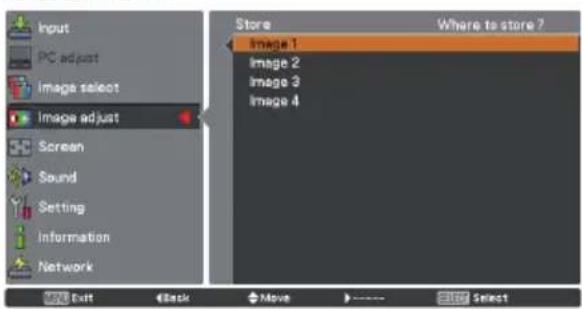
text_image
Input PC adjust Image select Image adjust Screen Sound Setting Information Network Store Where to store ? Image 1 Image 2 Image 3 Image 4 Exit Back Move Select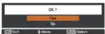
A confirmation box appears and then select Yes.
√Note:
Progressive can not be selected when the input signal is 480p, 575p or 720p (p.38).
Screen Setting
This projector has the picture screen resize function, which enables you to customize the image size.
1 Press the MENU button to display the On-Screen Menu. Use the Point ▲▼ buttons to select Screen and then press the Point ▶ button or the SELECT button.
2 Use the Point ▲▼ buttons to select the desired item and then press the SELECT button.
Normal
Provide the image to fit the screen size while maintaining the aspect ratio of the input signal.
Full
Provide the full screen image.
Wide (16:9)
Provide the image at the 16:9 wide screen ratio.
Zoom
Pan the horizontal direction of the image and cut the vertical direction of the image to fit the screen size (16:9). Only for 4:3 video aspect ratio signals.
Natural wide
Expand the right and left sides of images naturally without changing the center areas.
Custom
Provide the last stored aspect screen image.
Custom adj.
Adjust the screen scale and position manually with this function.
Press the Point ▶ button at Custom adj. and the Custom adjustment menu is displayed on the screen, you can use the Point ▲▼ buttons to choose the item you want to adjust.
Scale H/V ..... Adjust the Horizontal/Vertical screen scale.
H&V ...... When set to On, the aspect ratio is fixed. The Scale V appears dimmed and becomes unavailable. Adjust Scale H, then the screen scale is automatically modified based on the aspect ratio.
Position H/V .. Adjust the Horizontal/Vertical screen position.
Common ..... Save the adjusted scale or position to all the inputs. Press the SELECT button at Common to display a confirmation box. To save the scale or position, press the SELECT button at Yes. When Custom is selected, the saved scale or position is used.
Reset ...... 'Reset the all adjusted values. Press the SELECT button at Reset to display a confirmation box. To reset, press the SELECT button at Yes.
Screen Menu
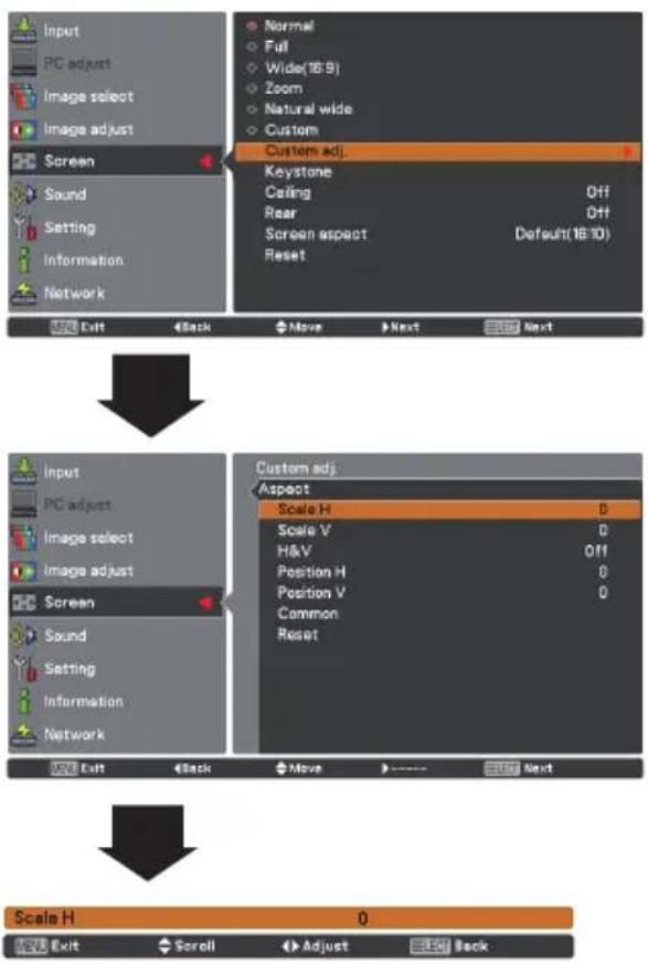
text_image
Input PC adjust Image select Image adjust Screen Sound Setting Information Network Normal Full Wide(16:9) Zoom Natural wide Custom Custom adj. Keystone Ceiling Off Rear Off Screen aspect Default(16:10) Reset Exit Back Move Next Next Input PC adjust Image select Image adjust Screen Sound Setting Information Network Custom adj. Aspect Scale H D Scale V D H&V Off Position H D Position V D Common Reset Exit Back Move Next Scale H 0 Exit Scroll Adjust Back√ Note:
- When no signal is detected, Normal is set automatically and the Aspect adjustment menu disappears.
- The adjustable range for Scale H/V and Position H/V is limited depending on the input signal.
Keystone
This function is used to adjust keystone distortion of the projected image. Use the Point ▲▼ buttons to choose the item you want to adjust.
Keystone
To correct keystone distortion, press the SELECT button.
Keystone appears on the screen. Use the Point ▲▼ buttons to correct keystone distortion (p. 23).
Store
To store or reset the keystone correction, press the Point ▶ button.
Store .... Keep the keystone correction even when the AC power cord is unplugged.
Reset ...... Release the keystone correction when the AC power cord is unplugged.
Ceiling
When this function is set to On, the picture will be top/bottom and left/right reversed. This function is used to project the image from a ceiling-mounted projector.
Rear
When this function is set to On, the picture will be left/right reversed. This function is used to project the image from rear of the screen.
Screen aspect
This function is used to project the image to a 4:3 or 16:9 projection screen.
Default (16:10) ....16:10 is the aspect of the LCD panel. The original Screen Menu is available.
16:9 ..... Set to a 16:9 projection screen.
4:3 .....Set to a 4:3 projection screen.
Reset
To reset the adjusted data, select Reset and press the SELECT button. A confirmation box appears and then select Yes. All adjustments will return to their previous figures.
Keystone
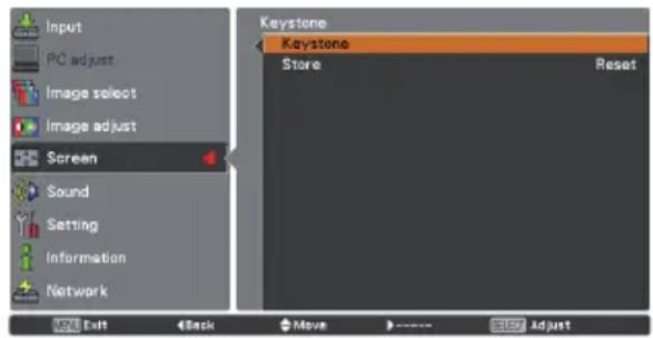
text_image
Input PC adjust Image select Image adjust Screen Sound Setting Information Network Keystone Keystone Store Reset Add Exit Back Move ---- Stop AdjustCeiling
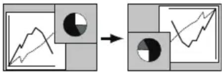
flowchart
graph LR
    A["Line Graph"] --> B["Circle Node"]
    B --> C["Line Chart"]
Rear
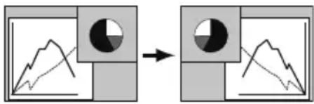
flowchart
graph LR
    A["Graph with shaded area"] --> B["Circular shape with shaded region"]
    B --> C["Transformed graph with arrow and circle"]
√Note:
When the 16:9 function is selected on Screen aspect menu, Wide (16:9) is not available in the PC and AV screen (pp.34, 42).
Setting
This projector has a Setting menu that allows you to set up the other various functions described below.
1 Press the MENU button to display the On-Screen Menu. Press the Point ▲▼ buttons to select Setting and press the Point ▶ button or the SELECT button to access the submenu items.
2 Use the Point ▲▼ buttons to select the desired item and then press the Point ▶ button or the SELECT button to access the selected item.
3 Use the Point ▲▼ buttons to select the desired item and then press the SELECT button.
Setting Menu
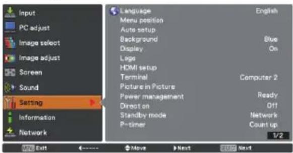
text_image
Input PC adjust Image select Image adjust Screen Sound Setting Information Network Language Menu position Auto setup Background Display Lega HDMI setup Terminal Picture in Picture Power management Direct on Standby mode P-timer English Blue On Computer 2 Ready Off Network Count up 1/2 Exit Move Next Next
Language
The language used in the On-Screen Menu is available in English, German, French, Italian, Spanish, Portuguese, Dutch, Swedish, Finnish, Polish, Hungarian, Romanian, Czech, Russian, Turkish, Arabic, Kazakh, Vietnamese, Chinese, Korean, Japanese and Thai.
Menu position
This function is used to change the position of the On-Screen Menu. Select Menu position and press the SELECT button.
The Menu position changes each time you press the SELECT button as follows. the center → the bottom left → the bottom right → the top left → the top right→.....
Language
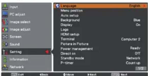
text_image
Input PC adjust Image select Image adjust Screen Sound Setting Information Network Language Menu position Auto setup Background Display Logo HDMI setup Terminal Picture in Picture Power management Direct on Standby mode P-timer English Blue On Computer 2 Ready Off Network Count up 1/2 Exit Back Move Next Next
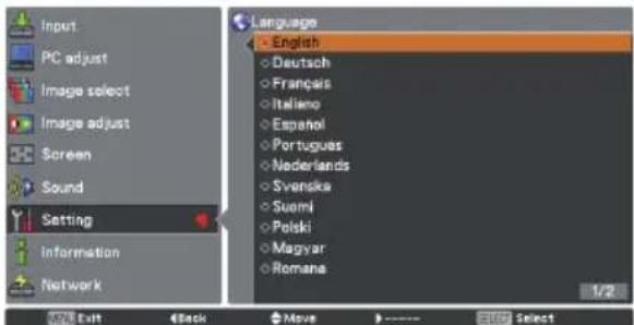
text_image
Input PC adjust Image select Image adjust Screen Sound Setting Information Network Language English Deutsch Français Italiano Español Portugues Nederlands Svenska Suomi Polski Magyar Romana 1/2 Exit Back Move SelectAuto setup
This function enables Input search, Auto PC adj. and Auto Keystone adjustment by pressing the AUTO SETUP button on the top control or the AUTO SET button on the remote control. Settings for those functions can be altered as follows:
Input search
This function detects the input signal automatically. When a signal is found, the search will stop. Use the Point ▲▼ buttons to select one of the following options.
Off ..... Input search does not work.
On 1..... Input search works under the following situation.
- When pressing the AUTO SET button on the remote control.
- When pressing the AUTO SETUP button on the top control.
On 2.....Input search works under the following situation.
- When turning on the projector by pressing the ON/STAND-BY button on the top control or the remote control.
- When pressing the AUTO SET button on the remote control.
- When pressing the AUTO SETUP button on the top control.
- When the current input signal is cut off.*
* If the No show or Freeze function is active, cancel it to activate the Input search. It is also unavailable when On-Screen menu is displayed.
Auto PC adj.
On......Enables Auto PC Adjustment when pressing the AUTO SET button on the remote control or the AUTO SETUP button on the top control.
Off....Disables Auto PC Adjustment.
Auto keystone
Auto....Always works and corrects keystone distortion according to the projector's tilt.
Manual.....Works only when pressing the AUTO SET button on the remote control or the AUTO SETUP button on the top control.
Off......Disables Auto Keystone.
√Note:
- While Input search is set to On 1 or On 2, the status of Input and Lamp are displayed every time the signal is switched.
- Only the last selected input source can be detected.
Auto setup
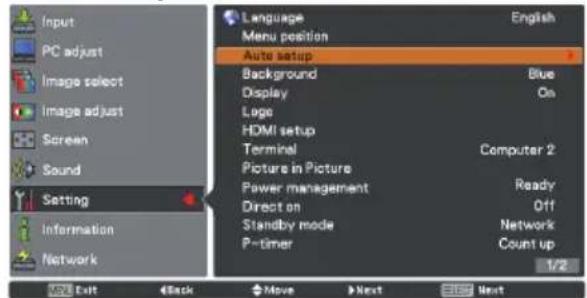
text_image
Input PC adjust Image select Image adjust Screen Sound Setting Information Network Language Menu position Auto setup Background Display Logo HDMI setup Terminal Picture in Picture Power management Direct on Standby mode P-timer English Blue On Computer 2 Ready Off Network Count up 1/2 Exit Back Move Next Next
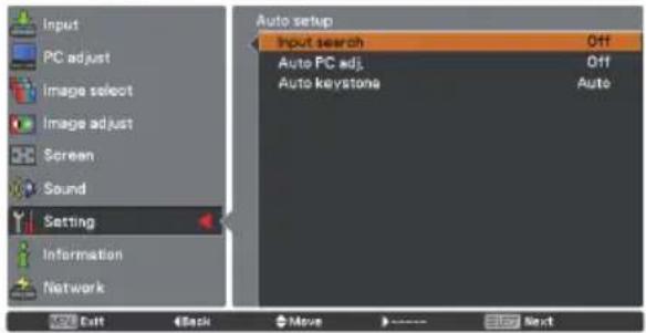
text_image
Input PC adjust Image select Image adjust Screen Sound Setting Information Network Auto setup Input search Off Auto PC adj. Off Auto keystone Auto Exit Back Move Next
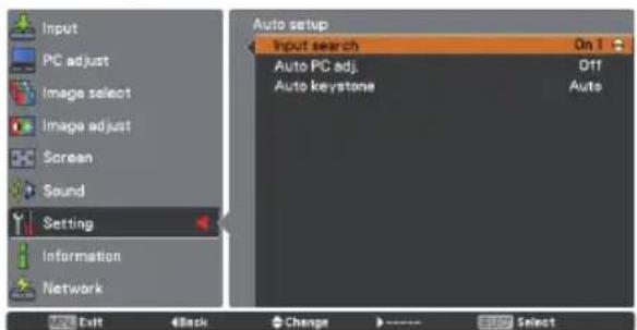
text_image
Input PC adjust Image select Image adjust Screen Sound Setting Information Network Auto setup Input search On 1 Auto PC adj. Off Auto keystone Auto Exit Back Change Select√Note:
- During Input search is in progress, If the MENU button or the ON/STAND-BY button is pressed, Input search will stop. If the COMPUTER 1/2 or VIDEO or COMPONENT or S-VIDEO or HDMI button is pressed, Input search will stop and go back to the button's input signal.
- Input search, Auto PC adj. and Auto keystone can not be set Off at the same time.
• Auto keystone corrects vertical distortion only, not correct horizontal distortion. - The Auto keystone function can not work when the Ceiling feature is set On in the Screen menu (pp. 35, 43).
- Perfect correction of the image distortion can not be ensured with the Auto setup function. If the distortion is not corrected properly by pressing the AUTO SETUP or the AUTO SET button, adjust manually by pressing the KEYSTONE button on the remote control or selecting Keystone in the Setting menu (pp. 35, 43).
- Fine sync, Total dots, Horizontal and Vertical of some computers cannot be fully adjusted with the Auto PC Adjustment function. When the image is not provided properly with this operation, manual adjustments are required (pp. 30-31).
Background
Select the background screen for when no input signal is detected. Press the Point ▲▼ buttons to switch between each option.
Blue......Project a blue background.
User......Project an image captured in the Logo setting.
Black.....Project a black background.
Display
This function decides whether to display On-Screen Displays.
On .... Show all the On-Screen displays. Use this function when you want to project images after the lamp becomes bright enough. The factory default setting is in this option.
Countdown off ... Show the input image instead of the countdown when turning on the projector. Use this function when you want to project the image as early as possible even when the lamp is not bright enough.
Off ...... Hide the On-Screen Displays except:
- On-Screen Menu.
• Power off? (p. 20) - P-Timer display.
- No signal for Power management (p. 49)
- Please wait ...
- Arrows for the True function in the Screen Menu. (p. 34)
Logo (Logo and Logo PIN code lock settings)
This function allows you to customize the screen logo with Logo select, Capture, Logo PIN code lock and Logo PIN code change functions.
√Note:
When On is selected in the Logo PIN code lock function, Logo select and Capture functions cannot be selected.
Logo select
This function decides on the starting-up display from among following options.
User ..... Show the image you captured.
Default ... Show the factory-set logo.
Off ...... Show the countdown display only.
Logo select
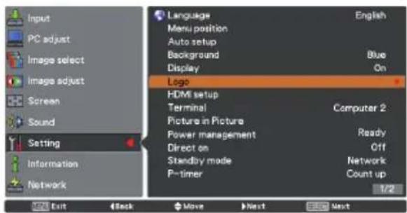
text_image
Input PC adjust Image select Image adjust Screen Sound Setting Information Network Language Menu position Auto setup Background Display English Blue On Logo HDMI setup Terminal Picture in Picture Power management Direct on Standby mode P-timer Computer 2 Ready Off Network Count up 1/2 Exit Back Move Next Next
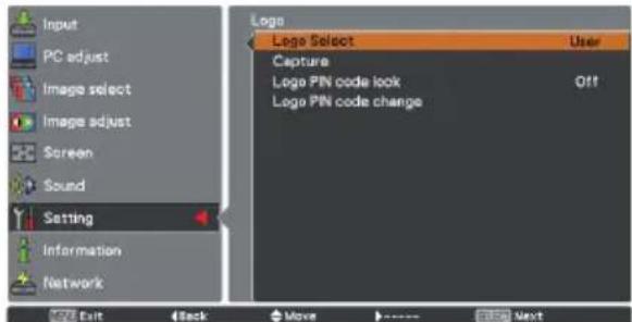
text_image
Input PC adjust Image select Image adjust Screen Sound Setting Information Network Login Logo Select User Capture Logo PIN code look Off Logo PIN code change Exit Back Move Next
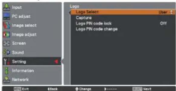
text_image
Input PC adjust Image select Image adjust Screen Sound Setting Information Network Exit Stack Change Next Logo Select Capture Logo PIN code lock Off Logo PIN code changeCapture
This function enables you to capture an image being projected to use it for a starting-up display or interval of presentations.
Select Capture and press the SELECT button. A confirmation box appears and select Yes to capture the projected image.
After capturing the projected image, go to the Logo select function and set it to User. Then the captured image will be displayed the next time you turn on the projector or when you press the NO SHOW button (p. 26).
To cancel the capture function, select Yes in the Quit? confirmation box.
√Note:
- Before capturing an image, select Standard in the Image select Menu to capture a proper image (pp. 32,39).
- The output image resolution from a computer can be supported up to the panel resolution (1280 x 800).
- When capturing the image that has been adjusted by the Keystone function, the adjusted data is automatically reset and the projector captures an image without keystone correction.
- When Logo PIN code lock function is set to On, Logo select and Capture can not be selected.
- When starting to capture a new image, the previously stored image is cleared even if you cancel the capturing.
- When there is no captured image or it is interrupted while capturing an image, User can not be selected, you can only switch between Default and Off.
Logo PIN code lock
This function prevents an unauthorized person from changing the screen logo.
Off ...... The screen logo can be changed freely from the Logo Menu (p. 46).
On .... The screen logo cannot be changed without a Logo PIN code.
If you want to change the Logo PIN code lock setting, press the SELECT button and the Logo PIN code dialog box appears. Enter a Logo PIN code by following the steps below. The initial Logo PIN code is set to "4321" at the factory.
Capture
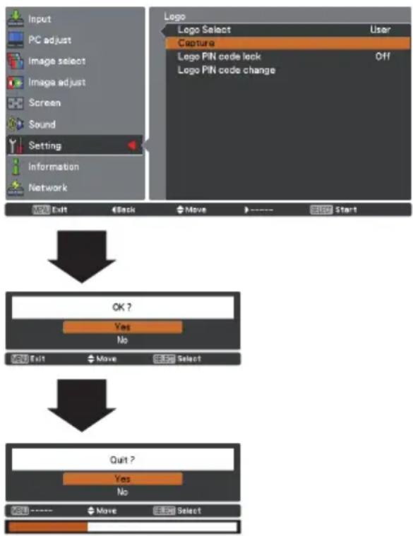
flowchart
graph TD
    A["Input"] --> B["PC adjust"]
    B --> C["Image select"]
    C --> D["Image adjust"]
    D --> E["Screen"]
    E --> F["Sound"]
    F --> G["Setting"]
    G --> H["Information"]
    H --> I["Network"]

    J["Logo Select"] --> K["User"]
    K --> L["Capture"]
    L --> M["Logo PIN code lock"]
    M --> N["Off"]
    N --> O["Logo PIN code change"]

    P["OK ?"] --> Q["Yes"]
    P --> R["No"]
    S["Quit ?"] --> T["Yes"]
    S --> U["No"]
Logo PIN code lock
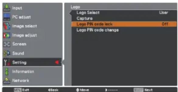
text_image
Input PC adjust Image select Image adjust Screen Sound Setting Information Network Logic Select Capture Logo PIN code lock Off Logo PIN code change Logic Exit Back Move NextEnter a Logo PIN code
Use the Point ▲▼ buttons to enter a number. Press the Point ◀▶ buttons to fix the number and move the red frame pointer to the next box. The number changes to *. If you fixed an incorrect number, use the Point ◀▶ buttons to move the pointer to the number you want to correct, and then enter the correct number.
Repeat this step to complete entering a four-digit number.
After entering the four-digit number, move the pointer to Set. Press the SELECT button so that you can start to operate the projector.
If you entered an incorrect Logo PIN code, Logo PIN code and the number (****) will turn red for a moment. Enter the correct Logo PIN code all over again.
Enter a Logo PIN code
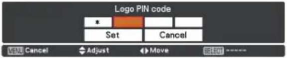
text_image
Logo PIN code Set Cancel Cancel Adjust Move
After a correct Logo PIN code is entered, the following dialog box appears.
Change the Logo PIN code lock setting

text_image
Input PC adjust Image select Image adjust Screen Sound Setting Information Network LOGO Logo Select User Capture Logo PIN code lock 011 Logo PIN code change OK Exit Back Move >---- >> NextChange the Logo PIN code lock setting
Use the Point ▲▼ buttons to switch On or Off, and then press the SELECT button to make a choice.
Logo PIN code change
Logo PIN code can be changed to your desired four-digit number. Press the SELECT button to select Logo PIN code change. Current logo PIN code dialog box appears, use the Point
▲▼buttons to enter the current code. The New logo PIN code input dialog box appears. Set a new Logo PIN code, confirmation box appears, choose Yes to set the new Logo PIN code.
Be sure to note the new Logo PIN code and keep it on hand. If you lost the number, you could no longer change the Logo PIN code setting.
CAUTION:
WHEN YOU HAVE CHANGED THE LOGO PIN CODE, WRITE DOWN THE NEW PIN CODE IN COLUMN OF THE LOGO PIN CODE NO. MEMO ON PAGE 78, AND KEEP IT SECURELY. SHOULD THE LOGO PIN CODE BE LOST OR FORGOTTEN, THE LOGO PIN CODE SETTING CAN NO LONGER BE CHANGED.
Change the Logo PIN code
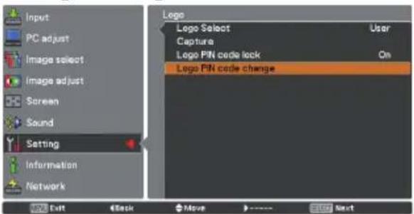
text_image
Input PC adjust Image select Image adjust Screen Sound Setting Information Network Logo Logo Select User Capture Logo PIN code lock On Logo PIN code change Exit Back Move Enter Next
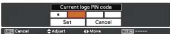
text_image
Current logo PIN code Set Cancel Cancel Adjust Move SLE
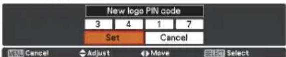
text_image
New logo PIN code 3 4 1 7 Set Cancel MENU Cancel Adjust Move SELECT Select
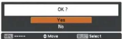
text_image
OK ? Yes No MENU ---- Move Select SelectHDMI setup
This function is only used for HDMI input source.
Image
Select Normal or Enhanced to match the video range setting of your HDMI Digital RGB equipment.
Sound
HDMI: When using the HDMI cable, select HDMI.
Both video and audio are transferred and you need not to connect any additional cables for audio.
Computer 2: When using the DVI-HDMI cable, select Computer 2 and connect the audio cable to COMPUTER IN 2 terminal.
The names for the output setting of Digital RGB vary from equipment to equipment. For details, refer to the owner's manual of your Digital RGB equipment.
When the black parts of the image are destroyed or stand out, please switch to Normal or Enhanced, and then switch the output type of the HDMI Digital RGB output equipment.
HDMI setup

text_image
Input PC adjust Image select Image adjust Screen Sound Setting Information Network Language Menu position Auto setup Background Display Logo HDMI setup Terminal Picture in Picture Power management Direct on Standby mode P-timer Computer 2 Ready Off Network Count up 1/2 100 Exit < Back > Move > Next >> Next
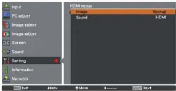
text_image
Input PC adjust Image select Image adjust Screen Sound Setting Information Network HDMI setup Image Normal Sound HDMI Exit Back Move Stop NextTerminal
The COMPUTER IN 2/MONITOR OUT terminal on the back of the projector is switchable for computer input or monitor output (p.9). Select Computer 2 or Monitor out with the Point ▲▼ buttons.
Computer 2 ..... computer input
Monitor out ...... monitor out
Terminal function is not available when selecting Computer 2 to the input source. Change the input source to the others (Computer 1, and so on) so that the Terminal function will be available. (pp. 25, 27, 37)
Picture in Picture
This function is used to project two images simultaneously by placing a separate small sub screen within or next to the main screen. Use the Point ▲▼ buttons to select Picture in Picture and then press the SELECT button or the Point ▶ button to access the submenu. Only the sound from the source of Main picture is valid, while the source of Sub picture cannot output the sound. ( In P in P, the larger picture is main picture, and the smaller one is sub picture; in P by P, the left picture is main picture, and the right one is sub picture.)
Mode
Select the Picture in Pictrue mode among P in P, P by P and Off.
P in P: Provide the images of Main picture and Sub picture at the ratio of Screen aspect in the Screen Menu.
P by P: Provide the images of Main picture and Sub picture at the ratio of Screen aspect in the Screen Menu.
Off: Turn off the Picture in Picture function.
Subpicture size
Press the Point ◀▶ buttons to changethe Subpicture size among Small, Middle and Large.
Subpicture position
Adjust the Subpicture position.
Press the Point ◀▶ buttons to change the Subpicture position.
Selecting the Sub picture
During Picture in Picture mode, and being undisplayed On Screen Menu, press the SELECT button to select Sub picture. (A red frame will be displayed on the selected picture.)
Switching Input Source
When Main picture or Sub picture is selected, input source can be set by pressing the INPUT button on the top control or COMPUTER1/2 or HDMI buttons on the remote control.
Picture in Picture
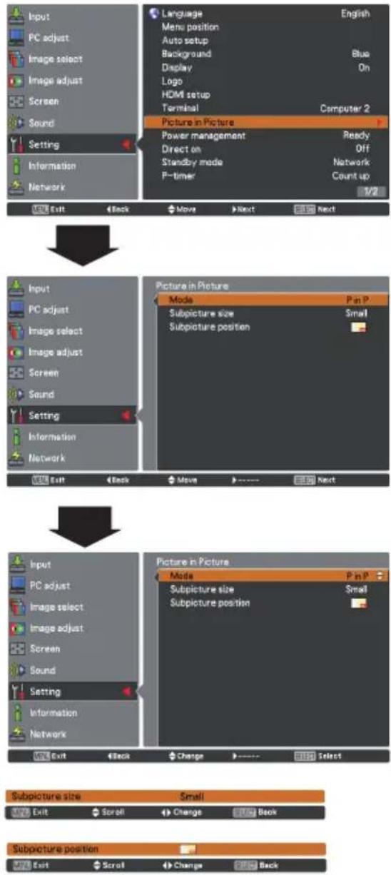
text_image
Input PC adjust Image select Image adjust Screen Sound Setting Information Network Language Menu position Auto setup Background Display Logo HDMI setup Terminal Picture in Picture Power management Ready Direct on Off Standby mode Network P-timer Count up 1/2 Exit Back Move Next Next Input PC adjust Image select Image adjust Screen Sound Setting Information Network Picture in Picture Mode Pan P Subpicture size Small Subpicture position View Back Move Next Next Input PC adjust Image select Image adjust Screen Sound Setting Information Network Picture in Picture Mode Pan P Subpicture size Small Subpicture position Exit Back Change Select Subpicture size Small Exit Scroll Change Back Subpicture position√Note:
- The Picture in Picture function is not available depending on the input signals and the selected input terminals. Refer to List of Picture in Picture for details. (p.77)
- When the input signal(s) is/are incompatible, × mark will be displayed on the Main/Sub picture.
- Subpicture size and Subpicture position works only under P in P mode.
Power management
For reducing power consumption as well as maintaining the lamp life, the Power management function turns off the projection lamp when the projector is not operated for a certain period.
Select one of the following options:
Ready ...... When the lamp has been fully cooled down, the POWER indicator changes to green blinking. In this condition, the projection lamp will be turned on if the input signal is reconnected or any button on the top control or remote control is pressed.
Shut down ... When the lamp has been fully cooled down, the power will be turned off.
Off ...... Power management function is off.
Timer ...... If the input signal is interrupted and no button is pressed for more than 30 seconds, the timer display with No signal appears. It starts the countdown until the lamp is turned off. Use the Point ▲▼ buttons to set the Timer (1\~30 min).
√Note:
Factory default is Ready: 5 min.
Power management

text_image
No signal 04:50Time left before Lamp is off.
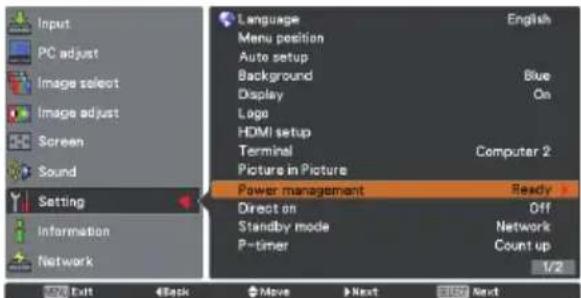
text_image
Input PC adjust Image select Image adjust Screen Sound Setting Information Network Language Menu position Auto setup Background Display Logo HDMI setup Terminal Picture in Picture Power management Ready Direct on Standby mode P-timer Off Network Count up English On Computer 2 1/2 Exit Back Move Next Next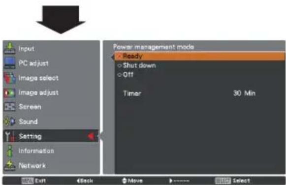
text_image
Input PC adjust Image select Image adjust Screen Sound Setting Information Network Power management mode Ready Shut down Off Timer 30 Min Exit Back Move >---- Select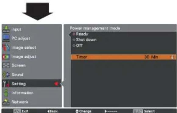
text_image
Input PC adjust Image select Image adjust Screen Sound Setting Information Network Power management mode Ready Shut down Off Timer 30 Min Exit Cancel Change SelectDirect on
When this function is set to On, the projector will be automatically turned on just by connecting the AC power cord to a wall outlet.
√Note:
Be sure to turn off the projector properly (see "Turning Off the Projector" on page 20). If the projector is turned off in the incorrect sequence, the Direct on function will not work properly.
Standby mode
This function is available when operating the projector via network.
Network .. Supply the power to the network function even after turning off the projector by pressing the ON/STAND-BY button on the remote control. You can turn on/off the projector via network, modify network environment, and receive an e-mail about projector status while the projector is powered off.
Eco ...... Select Eco when you do not use the projector via network. The projector's network function will stop when turning off the projector.
Refer to the owner's manual of "Network Setup and Operation".
√Note:
When selecting Network, the cooling fans may be running depending on the temperature inside the projector even if the projector is turned off.
P-timer
This function allows you to change the setting of the P-timer and execute it.
Select one of the following options:
Count up ..... The P-timer display 000:00 appears on the screen and the count up starts (000:00-180:00)
Count down .. The time set in the Timer setting appears on the screen and the countdown starts.
Timer ...... Use the Point ▲▼ buttons to set the Timer (1-180 Min). Timer is available in Count down only. Factory default value is 10 Min.
Start .... It executes the count up or count down function. Press the SELECT button at Start and the indication changes into Stop.
To stop Count up or Count down, press the SELECT button at Stop on the screen menu, then the indication changes into Restart. Press the SELECT button at Restart to resume Count up or Count down.
Reset ...... Reset the P-timer values. Press the SELECT button at Reset
to return to the following value:
Count up ..... "000:00"
Count down ... Timer that you set
Exit ...... To exit the P-timer operation.
X: disabled O: enabled
| Eco | Network | |
| Serial command | × *1 | ○ |
| Network | × | ○ |
| Monitor Out | × | ○ |
| Audio Out | × | × *2 |
| Direct on | ○ | ○ |
*1 When Eco is selected, it is only possible to turn on the projector while using the RS-232C serial port.
*2 When switch the Standby MIC out function On and in Standby mode status, only MIC volume can be output.
P-TIMER

111:11
P-timer display
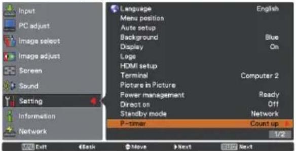
text_image
Input PC adjust Image select Image adjust Screen Sound Setting Information Network Language Menu position Auto setup Background Display Logo HDMI setup Terminal Picture in Picture Power management Direct on Standby mode P-timer English Blue On Computer 2 Ready Off Network Count up 1/2 Exit Back Move Next BUY Next
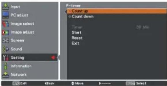
text_image
Input PC adjust Image select Image adjust Screen Sound Setting Information Network P-timer > Count up ○ Count down Timer 30 Me Start Reset Exit OK Exit Back Move > ---- STOP Select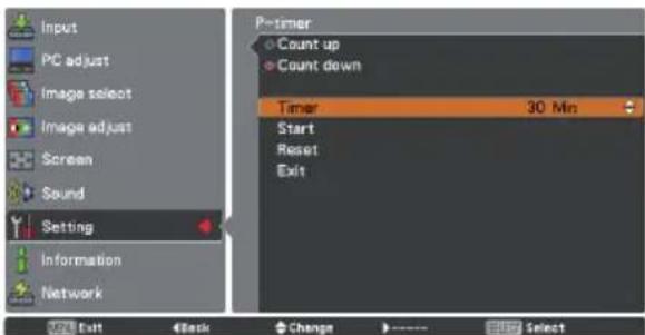
text_image
Input PC adjust Image select Image adjust Screen Sound Setting Information Network P-timer Count up Count down Timer 30 Min Start Reset Exit Exit Back Change SelectStop or Cancel the P-timer via Remote control
To stop the P-timer function, press the P-TIMER button. To cancel the P-timer, press and hold the P-TIMER button for a few seconds.
Closed caption
Closed Caption is a function that displays the audio portion of a TV program as text on the screen. You can turn on the feature and switch the channels. If the input signal contains closed captions, you can turn on the feature and switch the channels. Press the Point ▲▼ buttons to select Off, CC1, CC2, CC3 or CC4. If the Closed caption is not clear, you can change the text from Color to White.
Closed caption
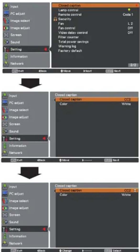
flowchart
graph TD
    A["Input"] --> B["PC adjust"]
    B --> C["Image select"]
    C --> D["Image adjust"]
    D --> E["Screen"]
    E --> F["Sound"]
    F --> G["Setting"]
    G --> H["Information"]
    H --> I["Network"]

    J["Closed caption"] --> K["Lamp control"]
    K --> L["Remote control"]
    L --> M["Security"]
    M --> N["Fan"]
    N --> O["L 2"]
    O --> P["Fan control"]
    P --> Q["Off"]
    Q --> R["Video delay control"]
    R --> S["Off"]
    S --> T["Filter counter"]
    T --> U["Total power savings"]
    U --> V["Warning log"]
    V --> W["Factory default"]

    X["Input"] --> Y["PC adjust"]
    Y --> Z["Image select"]
    Z --> AA["Image adjust"]
    AA --> AB["Screen"]
    AB --> AC["Sound"]
    AC --> AD["Setting"]
    AD --> AE["Information"]
    AE --> AF["Network"]

    AG["Closed caption"] --> AH["CC2"]
    AH --> AI["Color"]
    AI --> AJ["White"]

    AK["Input"] --> AL["PC adjust"]
    AL --> AM["Image select"]
    AM --> AN["Image adjust"]
    AN --> AO["Screen"]
    AO --> AP["Sound"]
    AP --> AQ["Setting"]
    AQ --> AR["Information"]
    AR --> AS["Network"]

    AT["Closed caption"] --> AU["CC2"]
    AU --> AV["Color"]
    AV --> AW["White"]

    AX["Input"] --> AY["PC adjust"]
    AY --> AZ["Image select"]
    AZ --> BA["Image adjust"]
    BA --> BB["Screen"]
    BB --> BC["Sound"]
    BC --> BD["Setting"]
    BD --> BE["Information"]
    BE --> BF["Network"]

    BG["Close caption"] --> BH["CC2"]
    BH --> BI["Color"]
    BI --> BJ["White"]
Press the Point ▲▼ buttons to select Off, CC1, CC2, CC3 or CC4, and then press the SELECT button.
√Note:
The Closed caption is available only under the situation below.
- When the input signal is Component (for adjustment only), Video or S-video, and the system is set to Auto or NTSC, the Closed caption is available.
- If the system is set to Auto, and choose NTSC as the input signal, the Closed caption function will be available.
Closed caption will be unavailable when under other setting conditions.
- The Closed caption function is unavailable when On-Screen menu and P-timer are displayed.
- The menu items of Closed caption are displayed in gray while it is not available.
Lamp control
Lamp control
This function allows you to change brightness of the screen.

Auto.....Brightness according to the input signal.

Normal..Normal brightness

Eco 1.....70%-80% of the normal brightness.

Eco 2.....50% of the normal brightness.
Lamp life control
Select the lamp operation when the total lighting time of a lamp exceeds the recommended total hours of use.
Mode 1...... The lamp can be turned on even after exceeding the recommended total hours of use.
Mode 2......The lamp can be turned on even after exceeding the recommended total hours of use. But the projector turns off automatically after 3 minutes.
Lamo control
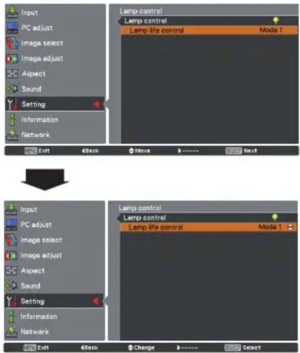
text_image
Input PC adjust Image select Image adjust Aspect Sound Setting Information Network Lamp control Lamp control Lamp life control Mode 1 Next Exit Back Move - - - - - - - - Input PC adjust Image select Image adjust Aspect Sound Setting Information Network Lamp control Lamp control Lamp life control Mode 1 Next Exit Back Change - - - - - -√Note:
- Lamp control can not be changed for a while after turning on the projector. Lamp needs some time to stabilize after the power is turned on. Stored lamp mode will be active after the lamp is stabilized.
- If Mode 2 has been selected and the projection lamp exceeds the recommended total hours of use, the replacement icon will be displayed at the time of power-on. Then the projector will turn off after 3 minutes.

Lamp replacement icon
- The Lamp replacement icon will not appear when the Display function is set to Off (p.46), during Freeze (p.25), or No show (p.26).
Remote control
This projector provides two different remote control codes: the factory-set initial code (Code 1) and the secondary code (Code 2). This switching function prevents remote control interference when operating several projectors or video equipment at the same time.
When operating the projector in Code 2, both the projector and the remote control must be switched to Code 2.
To change the code for the projector:
Select either Code 1 or Code 2 in this Setting Menu.
To change the code for the remote control:
Press and hold both the MENU and IMAGE buttons together for 5 seconds or more. After changing the code, make sure the remote control operates properly.
Remote control
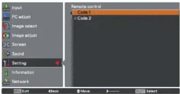
text_image
Input PC adjust Image select Image adjust Screen Sound Setting Information Network Remote control Code 1 Code 2 OK Exit Back Move ---- Skip Select√Note:
- When different codes are set on the projector and on the remote control, any operation cannot be made. In that case, switch the code on the remote control to fit the code on the projector.
- If the batteries are removed from the remote control for a long period of time, the remote control code will be reset.

Security (Key lock and PIN code lock)
This function allows you to use the Key lock and PIN code lock function to set the security for the projector operation.
Key lock
This function locks the top control and remote control buttons to prevent operation by unauthorized persons.
Select Key lock and then press the SELECT button and select the desired item by pressing the Point ▲▼ buttons.

...... Unlocked.

...... Lock the operation of the top control. To unlock, use the remote control.

...... Lock the operation of the remote control. To unlock, use the top control.
If the top control accidentally becomes locked and you do not have the remote control nearby or there is something wrong with your remote control, contact the dealer where you purchased the projector or the service center.
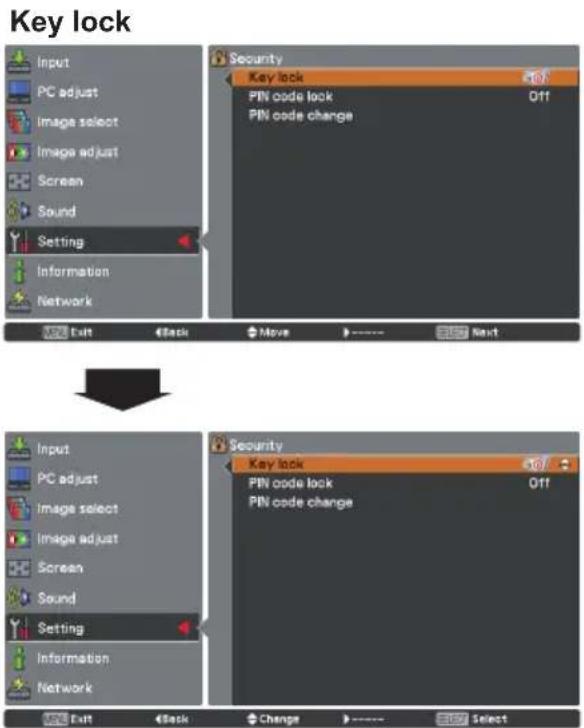
text_image
Key lock Input PC adjust Image select Image adjust Screen Sound Setting Information Network Exit Back Move Next Security Key lock PIN code lock Off PIN code change ↓ ↓ ↓ ↓ ↓ ↓ ↓ ↓ ↓ ↓ ↓ ↓ ↓ ↓ ↓ ↓ ↓ ↓ ↓ ↓ ↓ ↓ ↓ ↓ ↓ ↓ ↓ ↓ ↓ ↓ ↓ ↓ ↓ ↓ ↓ ↓ ↓ ↓ ↓ ↓ ↓ ↓ ↓ ↓ ↓ ↓ ↓ ↓ ↓ ↓ ↑ ↑ ↑ ↑ ↑ ↑ ↑ ↑ ↑ ↑ ↑ ↑ ↑ ↑ ↑ ↑ ↑ ↑ ↑ ↑ ↑ ↑ ↑ ↑ ↑ ↑ ↑ ↑ ↑ ↑ ↑ ↑ ↑ ↑ ↑ ↑ ↑ ↑ ↑ ↑ ↑ ↑ ↑ ↑ ↑ ↑ ↑ ↑ ↑ ↑ →PIN code lock
This function prevents the projector from being operated by unauthorized persons and provides the following setting options for security.
Off ...... Unlocked.
On 1 ...... Enter the PIN code every time turning on the projector.
On 2 ...... Enter the PIN code to operate the projector once the power cord is disconnected; as long as the AC power cord is connected, the projector can be operated without a PIN code.
Whenever you change the PIN code lock setting or the PIN code (the four-digit number), you are required to enter the PIN code. The "1234" is set as the initial PIN code at the factory.
If you want to change the PIN code lock setting, press the SELECT button and the PIN code dialog box appears.
When the projector is locked with the PIN code, the Security icon appears on the guide.
PIN code lock
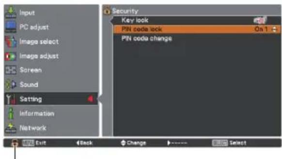
text_image
Input PC adjust Image select image adjust Screen Sound Setting Information Network Security Key look PIN code lock On 1 PIN code change Exit Back Change SelectWhen the projector is locked with the PIN code, the Security icon appears on the guide.
Enter a PIN code
Use the Point ▲▼ buttons to enter a number. Press the Point ◀▶ buttons to fix the number and move the red frame pointer to the next box. The number changes to *. If you fixed an incorrect number, use the Point ◀▶ buttons to move the pointer to the number you want to correct, and then enter the correct number.
Repeat this step to complete entering a four-digit number.
After entering the four-digit number, move the pointer to Set. Press the SELECT button so that you can change the following PIN code lock setting.
If you entered an incorrect PIN code, PIN code and the number (****) will turn red for a moment. Enter the correct PIN code all over again.
Change the PIN code lock setting
Use the Point ▲▼ buttons to select Off, On 1 or On 2, and then press the SELECT button to make a choice.
Change the PIN code
The PIN code can be changed to your desired four-digit number. Press the SELECT button to select PIN code change. Pin code dialog box appears, use the Point ▲▼ buttons to enter the current code. The New PIN code input dialog box appears. Set a new PIN code.
CAUTION:
WHEN YOU HAVE CHANGED THE PIN CODE, WRITE DOWN THE NEW PIN CODE IN COLUMN OF THE PIN CODE NO. MEMO ON PAGE 78, AND KEEP IT SECURELY. IF YOU FORGET YOUR PIN CODE, THE PROJECTOR CAN NO LONGER BE STARTED.
Enter a PIN code
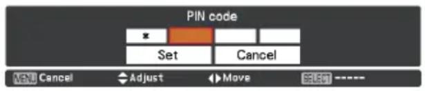
text_image
PIN code Set Cancel MENU Cancel Adjust Move SELECT ----Change the PIN code
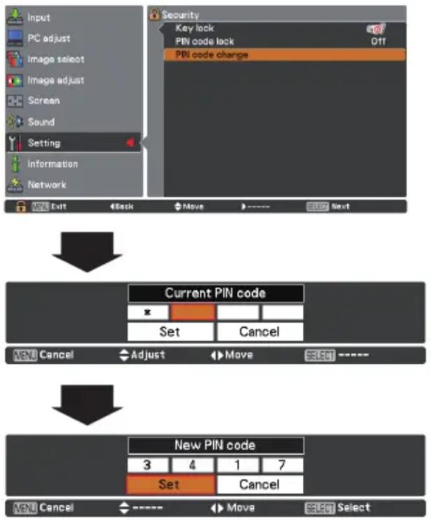
flowchart
graph TD
    A["Input"] --> B["PC adjust"]
    B --> C["Image select"]
    C --> D["Image adjust"]
    D --> E["Screen"]
    E --> F["Sound"]
    F --> G["Setting"]
    G --> H["Information"]
    H --> I["Network"]

    J["Security"] --> K["Key lock"]
    K --> L["PIN code lock"]
    L --> M["Off"]
    M --> N["PIN code change"]

    O["Current PIN code"] --> P["X"]
    P --> Q["Set"]
    Q --> R["Cancel"]

    S["New PIN code"] --> T["3"]
    T --> U["4"]
    U --> V["1"]
    V --> W["7"]
    W --> X["Set"]
    X --> Y["Cancel"]

    Z["Menu Cancel"] --> AA["----"]
    AA --> AB["Move"]
    AB --> AC["Select"]
Fan
This function provides the following options in the cooling fans' operation when the projector is turned off (p.20).
L 1 .... Normal operation
L 2 .... Slower, lower-sound and longish-time than the normal operation (L 1).
Fan control
Choose the running speed of cooling fans from the following options according to the ground elevation under which you use the projector.
Off...... Normal speed. Set this function to Off when using the projector in non- high altitude environment.
On 1...... Faster than Off mode. Select this mode when using the projector in high altitudes (about 1,200 meters or more above the sea level) where the fans have less cooling effect.
On 2...... Faster than On 1 mode. Select this mode when using the projector in higher altitudes than above where the fans have lesser cooling effect.
√Note:
- The fan noise becomes louder in On 1 and On 2.
- Failure to set the running speed of cooling fans properly may affect the projector life.
Video delay control
When you want to make a digital processing of a projected image faster, set this function.
Use the Point ▲▼ buttons, select an item of Off or On.
√Note:
Noise reduction and Progressive can not be selected when Video delay control function is set to On.
Filter counter
This function is used to set a frequency for the filter replacement.
Use the Point ▲▼ buttons to select Filter counter and then press the Point ▶button or the SELECT button to access the submenu items.
Filter counter....Show the total accumulated time of the filter use timer setting.
Timer......To set a timer, when the projector reaches the time, the Filter warning icon (Fig.1) appears on the screen and the total accumulated time turns red, indicating that the filter replacement is necessary.
Filter counter reset.. After replacing the filter, be sure to reset the timer. The Filter warning icon will not turn off until the filter counter is reset. For details about resetting the timer, refer to "Resetting the Filter Counter" on page 61.
Fig.1 Filter warning icon

Filter warning icon appears on the screen at a set time (Off/1000H/2000H/3000H/4000H/5000H/6000H).
Filter counter
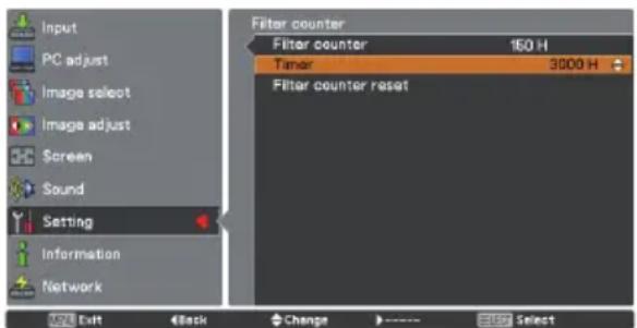
text_image
Input PC adjust Image select Image adjust Screen Sound Setting Information Network Filter counter Filter counter 150 H Timer 3000 H Filter counter reset ADD Exit Back Change >---- SelectPress the SELECT button to select Timer, and then use the Point ▲▼ buttons to set the timer. Select from (Off/1000H/2000H/3000H/4000H/5000H/6000H) depending on the use environment.
√Note:
- This icon also appears at turning on.
- The Filter warning icon (Fig.1) will not appear when the Display function is set to Off (p.46), during Freeze (p.25), or No show (p.26).
Total power savings
This function displays the saved amount of power and the exhausted CO2 of the projector.
Total power
savings.....Show the total accumulated power savings of the projector and display the total amount of CO2 exhausted from the projector.
Reset......Reset the figures of the total power savings and the exhausted CO2.
Warning log
This function records anomalous operations while the projector is in operation and use it when diagnosing faults. Up to 10 warning logs are displayed with the latest warning message at the top of the list, followed by previous warning messages in chronological order.
√Note:
When the Factory default function is executed, all the warning log records will be deleted.
Factory default
This function returns all setting values except for the User logo, PIN code lock, Logo PIN code lock, Lamp counter and Filter counter and Total power savings to the factory default settings.
Total power savings
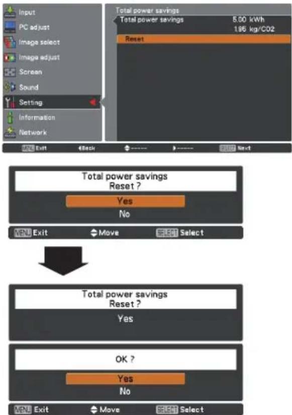
flowchart
graph TD
    A["Input"] --> B["PC adjust"]
    B --> C["Image select"]
    C --> D["Image adjust"]
    D --> E["Screen"]
    E --> F["Sound"]
    F --> G["Setting"]
    G --> H["Information"]
    H --> I["Network"]
    J["Total power savings"] --> K["5.00 kWh"]
    K --> L["1.96 kg/CO2"]
    M["Reset"] --> N["Output"]
    O["Menu Exit"] --> P["Back"]
    Q["Move"] --> R["Select"]
    S["OK ?"] --> T["Yes"]
    U["No"] --> V["No"]
Factory default
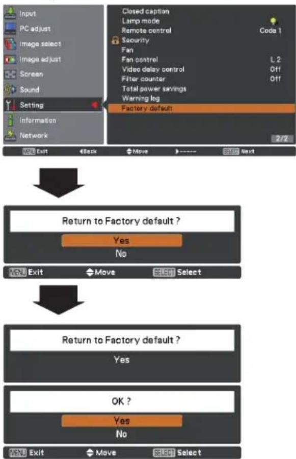
flowchart
graph TD
    A["Input"] --> B["PC adjust"]
    B --> C["Image select"]
    C --> D["Image adjust"]
    D --> E["Screen"]
    E --> F["Sound"]
    F --> G["Setting"]
    G --> H["Information"]
    H --> I["Network"]

    J["Closed caption"] --> K["Lamp mode"]
    K --> L["Remote control"]
    L --> M["Security Fan"]
    M --> N["Fan control"]
    N --> O["Video delay control"]
    O --> P["Filter counter"]
    P --> Q["Total power savings"]
    Q --> R["Warning log"]
    R --> S["Factory default"]

    T["Return to Factory default ?"] --> U["Yes"]
    U --> V["No"]

    W["Exit"] --> X["Move"] --> Y["Select"]

    Z["Return to Factory default ?"] --> AA["Yes"]
    AA --> AB["OK ?"]
    AB --> AC["Yes"]
    AC --> AD["No"]

    AE["Next"] --> AF["Next"]
Input Source Information Display
The Information Menu is used for checking the status of the image signal being projected and the operation of the projector.
Direct Operation
The information menu changes each time you press the INFO. button on the remote controller as follows.
page 1/2 → page 2/2 → hide → page 1/2 → •••• While the information menu is displayed, press the Point ◀▶ buttons to display the previous or next page.
Menu Operation
Press the Point ▲▼ buttons to select the Information. The Information Menu is displayed. See below for displayed information.
Input
The selected input source is displayed.
H-sync freq.
The horizontal frequency of the input signal is displayed in KHz, or - - - - KHz when no signal.
V-sync freq.
The vertical frequency of the input signal is displayed in Hz, or - - - - Hz when no signal. Numbers of Hz doubles when during Interlace.
Screen
The selected Screen size is displayed.
Language
The selected language is displayed.
Lamp status
The selected lamp mode is displayed.
Lamp counter
The cumulative lamp operating time is displayed.
Power management
Shut down, Ready, Off Timer are displayed.
Key lock
The selected Key lock icon is displayed.
PIN code lock
Off or On 1 or On 2 is displayed.
Remote control
The selected remote code is displayed.
SERIAL NO.
The serial number of the projector is displayed. The serial number is used to service the projector.
Total power savings
The saved amount of power and the exhausted CO2 are displayed.
Remote control
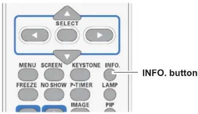
text_image
SELECT MENU SCREEN KEYSTONE INFO. FREEZE NO SHOW P-TIMER LAMP IMAGE PIP INFO. buttonInformation Menu
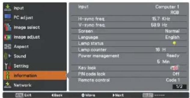
text_image
Input PC adjust Image select Image adjust Aspect Sound Setting Information Network Input Computer 1 RGB H-sync freq 15.7 KHz V-sync freq 59.9 Hz Screen Normal Language English Lamp status Lamp counter 16 H Power management Ready 5 Min Key lock Off PIN code lock Code 1 Remote control 1/2 Exit Back Move Next SOLED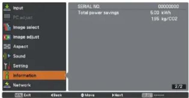
text_image
Input PC adjust Image select Image adjust Aspect Sound Setting Information Network SERIAL NO. 00000000 Total power savings 5.00 kWh 195 kg/CO2 2/2 Exit Back Move NextWARNING indicator
The WARNING indicator shows the state of the function which protects the projector. Check the state of the WARNING indicator and the POWER indicator to take proper maintenance.
The projector is shut down and the WARNING indicator is blinking red.
When the temperature inside the projector reaches a certain level, the projector will be automatically shut down to protect the inside of the projector. The POWER indicator is blinking while the projector is being cooled down. When the projector has cooled down enough (to its normal operating temperature), it can be turned on again by pressing the ON/STAND-BY button.
√Note:
The WARNING indicator continues to blink even after the temperature inside the projector returns to normal. When the projector is turned on again, the WARNING indicator stops blinking.
Top Control
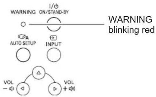
flowchart
graph TD
    A["WARNING ON/STAND-BY"] --> B["○"]
    B --> C["○"]
    C --> D["INPUT"]
    E["AUTO SETUP"] --> F["○"]
    G["VOL - ◀"] --> H["△"]
    I["△"] --> J["○"]
    K["VOL + ◀"] --> L["○"]
Then check the matters below:
- Did you provide appropriate space for the projector to be ventilated? Check the installing condition to see if the air vents of the projector are not blocked.
- Has the projector been installed near an Air-Conditioning/ Heating Duct or Vent? Move the installation of the projector away from the duct or vent.
- Are the filters clean? Replace the filters with new ones.
The projector is shut down and the WARNING indicator lights red.
When the projector detects an abnormal condition, it is automatically shut down to protect the inside of the projector and the WARNING indicator lights red. In this case, unplug the AC power cord and reconnect it, and then turn the projector on once again to verify operation. If the projector cannot be turned on and the WARNING indicator still lights red, unplug the AC power cord and contact the service center.
Top Control
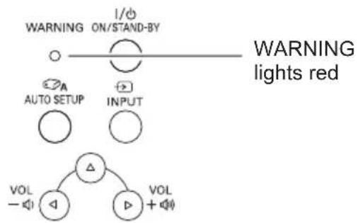
flowchart
graph TD
    A["WARNING ON/STAND-BY"] --> B["AUTO SETUP"]
    A --> C["INPUT"]
    D["VOL -"] --> E["△"]
    F["VOL +"] --> G["△"]
    H["1/Φ"] --> I["○"]
    J["○"] --> K["○"]
    L["○"] --> M["○"]
    N["VOL"] --> O["△"]
    P["VOL"] --> Q["△"]

WARNING
DO NOT LEAVE THE PROJECTOR WITH THE AC POWER CORD CONNECTED UNDER AN ABNORMAL CONDITION. IT MAY RESULT IN FIRE OR ELECTRIC SHOCK.
Replacing the Filters
Filter prevents dust from accumulating on the optical elements inside the projector. Should the filter become clogged with dust particles, it will reduce cooling fans' effectiveness and may result in internal heat buildup and adversely affect the life of the projector. If a "Filter warning" icon appears on the screen, replace the filters immediately. Replace the filters by following the steps below.
1 Turn off the projector and unplug the AC power cord from the AC outlet.
2 Turn over the projector and pull out the filter cover (bottom); pull up the handle and take out the whole filter (bottom.)
Press up the latches and pull out the filter cover (side); pull out the handle and take out the side filter.
3 Put new filters back into the position. Make sure that the filters are fully inserted to the projector.
4 Connect the AC power cord to the projector and turn on the projector.
CAUTION
- Do not operate the projector with the filters removed. Dust may accumulate on the optical elements degrading picture quality.
- Do not put anything into the air vents. Doing so may result in malfunction of the projector.
- Do not wash the filters with water or any other liquid matter. Otherwise the filters may be damaged.
RECOMMENDATION
We recommend avoiding dusty/smoky environments when you operate the projector. Usage in these environments may cause poor image quality.
When using the projector under dusty or smoky conditions, dust may accumulate on a lens, LCD panels, or optical elements inside the projector degrading the quality of a projected image. When the symptoms above are noticed, contact your authorized dealer or service center for proper cleaning.
Resetting the Filter Counter
Be sure to reset the Filter counter after replacing the filter.
1 Press the MENU button to display the On-Screen Menu. Use the Point ▲▼ buttons to select Setting and then press the Point ▶ button or the SELECT button.
2 Use the Point ▲▼ buttons to select Filter counter and then press the Point ▶ or the SELECT button. Use the Point ▲▼ buttons or the SELECT button to select Filter counter reset and then press the SELECT button. Filter counter Reset? appears. Select Yes to continue.
3 Another confirmation dialog box appears, select Yes to reset the Filter counter.
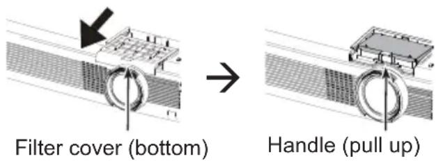
Filter cover (side)
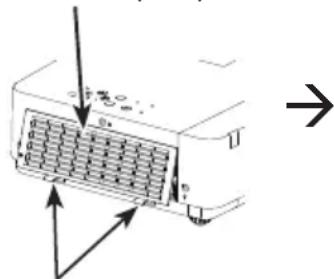
text_image
Diagram showing a device with internal grid structure and directional arrows, possibly indicating flow or movement.Latches (press up)
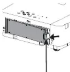
text_image
Technical diagram showing a mechanical assembly with labeled components and an arrow indicating direction of motion or force.Handle (pull out)
Filter counter reset
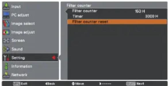
text_image
Input PC adjust Image select Image adjust Screen Sound Setting Information Network Filter counter Filter counter 150 H Timer 3000 H Filter counter reset Exit Back Move SUE Next
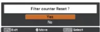
text_image
Filter counter Reset ? Yes No MENU Exit Move SELECT Select

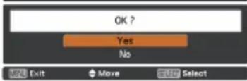
text_image
OK ? Yes No MENU Exit Move SelectFilter counter Reset? appears.
Select Yes, then another confirmation box appears.
Select Yes again to reset the Filter counter.
Attaching the Lens Cap
When moving this projector or while not using it over an extended period of time, attach the lens cap.
Attach the lens cap according to the following procedures.
1 Thread the string through the hole on the lens cap and then tie a knot in the string to secure it in place.
2 To pass the other end of the string into the hole on the bottom of the projector and pull at it.
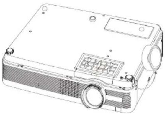
natural_image
Technical line drawing of a projector with visible internal components and mounting holes (no text or symbols)Cleaning the Projection Lens
Unplug the AC power cord before cleaning.
Gently wipe the projection lens with a cleaning cloth that contains a small amount of non-abrasive camera lens cleaner, or use a lens cleaning paper or commercially available air blower to clean the lens.
Avoid using an excessive amount of cleaner. Abrasive cleaners, solvents, or other harsh chemicals might scratch the surface of the lens.
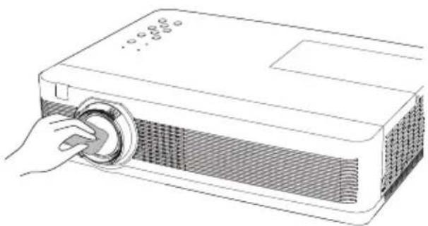
natural_image
Line drawing of a projector with a hand operating the button (no text or symbols)Cleaning the Projector Cabinet
Unplug the AC power cord before cleaning.
Gently wipe the projector body with a soft dry cleaning cloth. When the cabinet is heavily soiled, use a small amount of mild detergent and finish with a soft dry cleaning cloth. Avoid using an excessive amount of cleaner. Abrasive cleaners, solvents, or other harsh chemicals might scratch the surface of the cabinet.
When the projector is not in use, put the projector in an appropriate carrying case to protect it from dust and scratches.
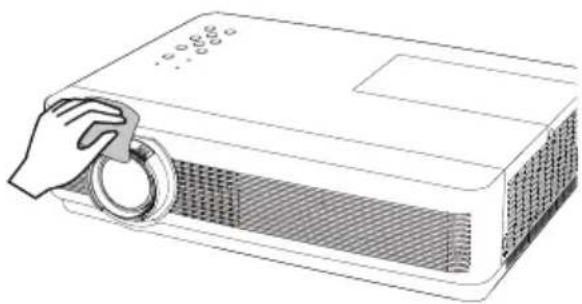
natural_image
Line drawing of a projector with a hand holding the lid (no text or symbols)
CAUTION
Do not use any flammable solvents or air sprays on the projector and in its vicinity. The explosion or fire hazard may occur even after the AC power cord is unplugged because the temperature inside the projector is extremely high due to the lamps. In addition, there is a risk that the internal parts may be damaged not only by the flammable air spray but also by the cold air.
Lamp Replacement
When the projection lamp of the projector reaches its end of life, the Lamp replacement icon appears on the screen and LAMP REPLACE indicator lights yellow. Replace the lamp with a new one promptly. The timing when the LAMP REPLACE indicator should light is depending on the lamp mode.
Top Control
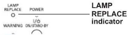
text_image
LAMP REPLACE POWER O I/O WARNING ON/STAND-BY LAMP REPLACE indicator
Lamp replacement icon
√Note:
- The Lamp replacement icon will not appear when the Display function is set to Off (p.46), during Freeze (p.25), or No show (p.26).
- When Mode 2 is selected in the Lamp life control menu, if the projection lamp of the projector reaches its end of life, the lamp replacement icon appears on the screen, and the projector is turned off automatically after 3 minutes.

CAUTION
Allow a projector to cool for at least 45 minutes before you open the Lamp Cover. The inside of the projector can become very hot.

CAUTION

CAUTION
For continued safety, replace with a lamp of the same type. Do not drop a lamp or touch a glass bulb! The glass can shatter and may cause injury.
When replacing the lamp because it has stopped illuminating, there is a possibility that the lamp may be broken.
If replacing the lamp of a projector which has been installed on the ceiling, you should always assume that the lamp is broken, and you should stand to the side of the lamp cover, not underneath it. Remove the lamp cover gently. Small pieces of glass may fall out when the lamp cover is opened. If pieces of glass get into your eyes or mouth, seek medical advice immediately.
Follow these steps to replace the lamp.
1 Unplug the AC power cord. Let the projector cool for at least 45 minutes.
2 Loosen the screw and open the lamp cover.
3 Loosen the three (3) screws that secure the lamp. Lift the lamp out of the projector by using the handle.
4 Replace the lamp with a new one and secure the three (3) screws. Make sure that the lamp is set properly. Close the lamp cover and secure the screw.
5 Connect the AC power cord to the projector and turn on the projector.
Lamp Cover
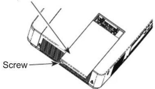
text_image
Screw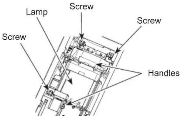
text_image
Lamp Screw Screw Screw HandlesORDER REPLACEMENT LAMP
Replacement lamp can be ordered through your dealer. When ordering a projection lamp, give the following information to the dealer.
• Model No. of your projector : LC-WB200
- Replacement Lamp Type No.: POA-LMP148
(Service Parts No. 610 352 7949)

CAUTION
LAMP HANDLING PRECAUTIONS
This projector uses a high-pressure lamp which must be handled carefully and properly.
Improper handling may result in accidents, injury, or create a fire hazard.
- Lamp life may differ from lamp to lamp and according to the environment of use. There is no guarantee of the same life for each lamp. Some lamps may fail or terminate their life in a shorter period of time than other similar lamps.
- If the projector indicates that the lamp should be replaced, i.e., if the LAMP REPLACE indicator lights up, replace the lamp with a new one IMMEDIATELY after the projector has cooled down.
(Follow carefully the instructions in the Lamp Replacement section of this manual.) Continuous use of the lamp with the LAMP REPLACE indicator lighted may increase the risk of lamp explosion.
- A Lamp may explode as a result of vibration, shock or degradation as a result of hours of use as its lifetime draws to an end. Risk of explosion may differ according to the environment or conditions in which the projector and lamp are being used.
IF A LAMP EXPLODES, THE FOLLOWING SAFETY PRECAUTIONS SHOULD BE TAKEN.
If a lamp explodes, disconnect the projector's AC plug from the AC outlet immediately. Contact an authorized service center for a checkup of the unit and replacement of the lamp. Additionally, check carefully to ensure that there are no broken shards or pieces of glass around the projector or coming out from the cooling air circulation holes. Any broken shards found should be cleaned up carefully. No one should check the inside of the projector except those who are authorized trained technicians and who are familiar with projector service. Inappropriate attempts to service the unit by anyone, especially those who are not appropriately trained to do so, may result in an accident or injury caused by pieces of broken glass.
Troubleshooting
Before calling your dealer or service center for assistance, check the items below once again.
- Make sure you have properly connected the projector to peripheral equipment as described on pages 14-16.
- Make sure all equipment is connected to AC outlet and the power is turned on.
- When the projector does not project an image from the connected computer, restart the computer.
Problem: – Solutions
No power - Plug the power cord of the projector into the AC outlet.
– See if the POWER indicator lights red.
- Wait until the POWER indicator stops blinking to turn on the projector again. The projector can be turned on after the POWER indicator turns red. See page 18.
- Check the WARNING indicator. If the WARNING indicator lights red, projector cannot be turned on. See page 70.
- Check the projection lamp. See page 63.
- Unlock the Key lock function for the projector. See page 55.
The initial display is not shown. – Make sure Off or Countdown off are not chosen at display function. See page 46.
The initial display is not same as the default set. – Make sure User or Off are not chosen at Logo (select) function. See page 46.
Input signal switches automatically. – Make sure Input search function is adjusted properly. (or does not switch automatically) See page 45.
An icon other than Input mode or Lamp mode icon appears. – That is the Lamp replacement icon or the Filter warning icon. See page 63 or 57.
Image is out of focus. - Adjust focus of the projector. See page 23.
- Provide proper distance between the projector and the projection screen. See page 13.
- Check the projection lens to see if it needs cleaning. See page 62.
- Moving the projector from a cool to warm place may result in moisture condensation on the projection lens. In such cases, leave the projector off and wait until condensation evaporates.
Image is Left/Right reversed. - Check the Ceiling/Rear function. See pages 35, 43.
Image is Top/Bottom reversed. – Check the Ceiling function. See pages 35, 43.
Picture is not bright enough. – Check if the Contrast or Brightness is adjusted properly. See pages 33, 40.
- Check if Image mode is selected properly. See pages 32, 39.
- Check the Lamp control function. See pages 25, 54.
- Check the LAMP REPLACE indicator. If it lights, the end of lamp life is approaching. Replace the lamp with a new one promptly.
See page 63.
| No image – Check the connection between your computer or video equipment and the projector. See pages 14-16.- See if the input signal is correctly output from your computer.Some laptop computers may need to change the setting for monitor output when connecting to a projector. See your computer's instruction manual for the setting.- It takes about 30 seconds to display an image after turning on the projector. See page 18.- Check the Input signal, color system, video system or computer system mode.- Make sure the temperature is not out of the specified Operating Temperature (41°F–95°F [5°C–35°C]).- When No show is operating, the image cannot be displayed.Press the NO SHOW button or any other button on the remote control. | ||
| No sound – Check the audio cable connection from audio input source.- Adjust the audio source.- Press the VOLUME + button. See page 24.- Press the MUTE button. See page 24.- When the AUDIO OUT is plugged-in, the projector's built-in speaker is not available.- Is the image projected? You will hear the Computer and VIDEO sound only when the image is projected. | ||
| The color is strange.- Make sure the Blackboard is not selected on Image select menu. See pages 32, 39. | - Check the Input signal, color system, video system or computer system mode.- Check the Input signal, color system, video system or computer system mode.- Check the Input signal, color system, video system or computer system mode.- Check the Input signal, color system, video system or computer system mode.- Check the Input signal, color system, video system or computer system mode.- Check the Input signal, color system, video system or computer system mode.- Check the Input signal, color system, video system or computer system mode.- Check the Input signal, color system, video systems, video system mode.- Check the Input signal, color system, video system or computer system mode.- Check the Input signal, color system, video system or computer system mode.- Check the Input signal, color system, video system or computer system mode.- Check the Input signal, color system, video system or computer system mode.- Check the Input signal, color system, video system or computer system mode.- Check the Input signal, color system, video system or computer system mode.- Check the Input signal, color systems, video system or computer system mode.- Check the Input signal, color systems, video system or computer system mode.- Check the Input signal, color systems, video system or computer system mode.- Check the Input signal, color systems, video system or computer system mode.- Check the Input signal, color systems, video system or computer system mode.- Check the Input signal, color systems, video system or computer system mode.- Check the Input signal, color systems, video system or computer system mode.- Check that the output is not selected at any function of the output is not selected at any function of the output is not selected at any function of the output is not selected at any function of the output is not selected at any function of the output is not selected at any function of the output is not selected at any function of the output is not selected at any function of the output is not selected at any function of the output is not selected at any function of the output is not selected at any function of the output is not selected at any function of 10000000000000000000000000000000000000000000000000000000000000000000000000000000000000000000000000000 | |
| Some displays are not seen during the operation. | - Check the Display function. See page 46. | |
| Auto PC adjustment function does not work. selected (see page 29), or when the signal is coming from the HDMI terminal. | - Check the Input signal. Auto PC adjustment function can not work when 480p, 575p, 720p, 480i, 575i, 1035i or 1080i is the signal is coming from the HDMI terminal. | |
| The setting does not remain after turning off power. pages 33, 41. | -Make sure you selected Store after adjusting setting. Some settings can not be stored if not registered with Store. See | |
| Power management does not work. | -Power management function can not work while Freeze or No show function is running. See page 49. | |
| Capture function does not work. | - Check the connection and the input signal to see if there is signal. | |
| Auto setup does not work properly.- Make sure On is not selected at the Ceiling function.See pages 35, 43. | -Make sure Off is not selected at any function of Auto setup. See page 45.- Make sure On is not selected at the Ceiling function.See pages 35, 43. | |
| Auto keystone function does not work even when the projector is tipped. | -Make sure the Auto keystone function is not set to Manual. Press the AUTO SETUP button on the top control. See pages 23, 45. | |
| The image is distorted or runs off. See pages 29-30, 34-35. | – Check PC adjust menu or Screen menu and adjust them. |
| PIN code dialog box appears at start-up. | – PIN code lock is being set. Enter a PIN code (the “1234” or number you have set). See pages 19, 55-56. |
| The Remote control does not work. – Make sure no obstruction is between the projector and remot controller.– Make sure you are not too far from the projector when using the remote control. Maximum operating range is 16.4'(5 m).– Make sure the code of the remote control is conformed to the projector's code. See page 54.– Unlock the Key lock function for the remote control function. See page 55. | |
| Indicator blinks or lights. | – Check the status of the projector with referring to "Indicators and projector Condition". See page 70. |
| The exclamation mark appears on the screen. | – Your operation is invalid. Operate correctly. |
| Top control does not work. | – The top control is not available if the top control is locked at Key lock under Security of Setting section. See page 55. |
| Unable to unlock the Logo PIN code lock, Security key lock or Security PIN code lock. | – Contact the dealer where you purchased the projector or the service center. |
WARNING :
High voltages are used to operate this projector. Do not attempt to open the cabinet.
If problems still persist after following all operating instructions, contact the dealer where you purchased the projector or the service center. Specify the model number and explain about the problem. We will advise you how to obtain service.

The CE Mark is a Directive conformity mark of the European Community (EC).

US LISTED
This symbol on the nameplate means the product is Listed by Underwriters Laboratories Inc. It is designed and manufactured to meet rigid U.L. safety standards against risk of fire, casualty and electrical hazards.
Menu Tree
Computer Input/HDMI/ Input/Video Input

flowchart
graph TD
    A["Input"] --> B["Computer 1"]
    A --> C["Computer 2"]
    A --> D["HDMI"]
    A --> E["Video"]
    A --> F["S-Video"]
    B --> G["RGB"]
    B --> H["Component"]
    B --> I["RGB(Scart)"]
    C --> J["RGB"]
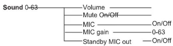
flowchart
graph TD
    A["Sound 0-63"] --> B["Volume"]
    A --> C["Mute On/Off"]
    A --> D["MIC"]
    A --> E["MIC gain"]
    A --> F["Standby MIC out"]
    D --> G["On/Off"]
    E --> H["0-63"]
    F --> I["On/Off"]
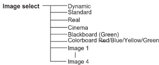
flowchart
graph TD
    A["Image select"] --> B["Dynamic"]
    A --> C["Standard"]
    A --> D["Real"]
    A --> E["Cinema"]
    A --> F["Blackboard (Green)"]
    A --> G["Colorboard Red/Blue/Yellow/Green"]
    A --> H["Image 1"]
    A --> I["Image 4"]

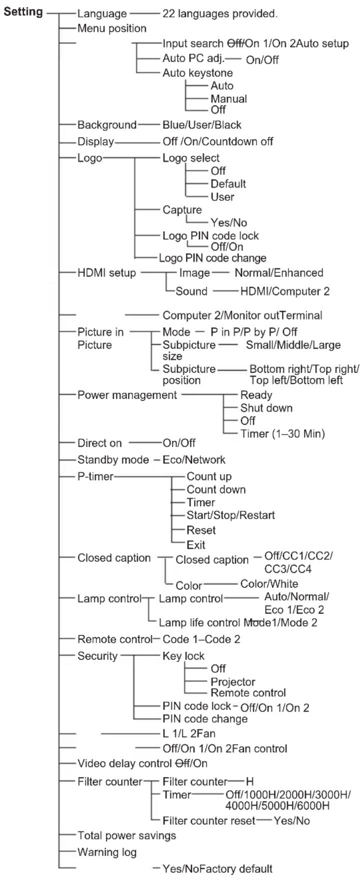
flowchart
graph TD
    A["Setting"] --> B["Language"]
    A --> C["Menu position"]
    B --> D["22 languages provided."]
    C --> E["Input search Off/On 1/On 2 Auto setup"]
    C --> F["Auto PC adj.— On/Off"]
    C --> G["Auto keystone"]
    G --> H["Auto"]
    G --> I["Manual"]
    G --> J["Off"]
    C --> K["Background"]
    K --> L["Blue/User/Black"]
    K --> M["Display"]
    M --> N["Off /On/Countdown off"]
    C --> O["Logo"]
    O --> P["Logo select"]
    P --> Q["Off"]
    P --> R["Default"]
    P --> S["User"]
    O --> T["Capture"]
    T --> U["Yes/No"]
    T --> V["Logo PIN code lock"]
    V --> W["Off/On"]
    V --> X["Logo PIN code change"]
    C --> Y["HDMI setup"]
    Y --> Z["Image — Normal/Enhanced"]
    Y --> AA["Sound — HDMI/Computer 2"]
    C --> AB["Picture in Picture"]
    AB --> AC["Mode — P in P/P by P/ Off"]
    AB --> AD["Subpicture — Small/Middle/Large size"]
    AB --> AE["Subpicture — Bottom right/Top right/ Top left/Bottom left"]
    C --> AF["Power management"]
    AF --> AG["Ready"]
    AG --> AH["Shut down"]
    AG --> AI["Off"]
    AG --> AJ["Timer (1–30 Min)"]
    C --> AK["Direct on — On/Off"]
    AK --> AL["Standby mode — Eco/Network"]
    C --> AM["P-timer"]
    AM --> AN["Count up"]
    AN --> AO["Count down"]
    AN --> AP["Timer"]
    AP --> AQ["Start/Stop/Restart"]
    AN --> AR["Reset"]
    AN --> AS["Exit"]
    C --> AT["Closed caption"]
    AT --> AU["Closed caption — Off/CC1/CC2/ CC3/CC4"]
    AT --> AV["Color — Color/White"]
    C --> AW["Lamp control"]
    AW --> AX["Lamp control — Auto/Normal/ Eco 1/Eco 2"]
    AW --> AY["Lamp life control Mode1/Mode 2"]
    C --> AZ["Remote control— Code 1–Code 2"]
    AZ --> BA["Code 1–Code 2"]
    AZ --> BB["Security"]
    BB --> BC["Key lock"]
    BC --> BD["Off"]
    BC --> BE["Projector Remote control"]
    BB --> BF["PIN code lock — Off/On 1/On 2"]
    BB --> BG["PIN code change"]
    CA["Video delay control Off/On"] --> CB["L 1/L 2Fan"]
    CB --> CC["Off/On 1/On 2 Fan control"]
    CA --> DD["Filter counter — Filter counter — H"]
    DD --> DE["Timer — Off/1000H/2000H/3000H/ 4000H/5000H/6000H"]
    DD --> CF["Filter counter reset — Yes/No"]
    CA --> CG["Total power savings"]
    CG --> CH["Warning log"]
    CG --> CI["- Yes/No Factory default"]
HDMI Input / Video Input
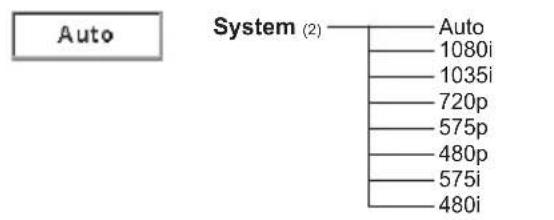
flowchart
graph TD
    A["Auto"] --> B["System (2)"]
    B --> C["Auto"]
    B --> D["1080i"]
    B --> E["1035i"]
    B --> F["720p"]
    B --> G["575p"]
    B --> H["480p"]
    B --> I["575i"]
    B --> J["480i"]
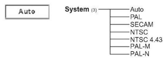
flowchart
graph TD
    A["Auto"] --> B["System (3)"]
    B --> C["Auto"]
    B --> D["PAL"]
    B --> E["SECAM"]
    B --> F["NTSC"]
    B --> G["NTSC 4.43"]
    B --> H["PAL-M"]
    B --> I["PAL-N"]
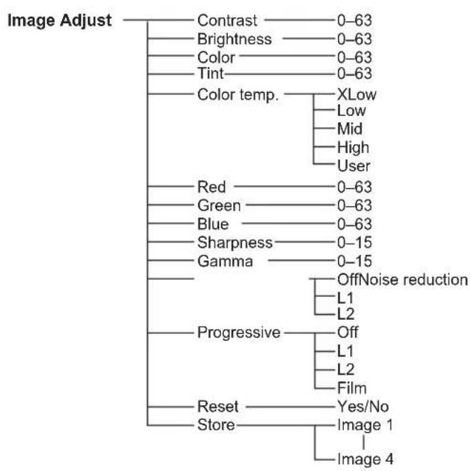
flowchart
graph TD
    A["Image Adjust"] --> B["Contrast"]
    A --> C["Brightness"]
    A --> D["Color"]
    A --> E["Tint"]
    A --> F["Color temp."]
    F --> G["XLow"]
    F --> H["Low"]
    F --> I["Mid"]
    F --> J["High"]
    F --> K["User"]
    F --> L["Red"]
    L --> M["0-63"]
    L --> N["Green"]
    N --> O["0-63"]
    L --> P["Blue"]
    P --> Q["0-63"]
    L --> R["Sharpness"]
    R --> S["0-15"]
    R --> T["Gamma"]
    T --> U["OffNoise reduction"]
    T --> V["L1"]
    T --> W["L2"]
    T --> X["Progressive"]
    X --> Y["Off"]
    Y --> Z["L1"]
    Y --> AA["L2"]
    Y --> AB["Film"]
    T --> AC["Reset"]
    AC --> AD["Yes/No"]
    AC --> AE["Store"]
    AE --> AF["Image 1"]
    AE --> AG["Image 4"]
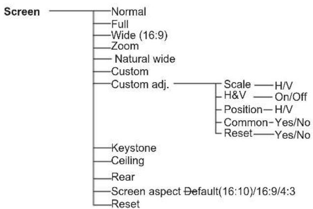
flowchart
graph TD
    A["Screen"] --> B["Normal"]
    B --> B1["Full"]
    B --> B2["Wide (16:9)"]
    B --> B3["Zoom"]
    B --> B4["Natural wide"]
    B --> B5["Custom"]
    B --> B6["Custom adj."]
    B6 --> C["Scale — H/V"]
    B6 --> D["H&V — On/Off"]
    B6 --> E["Position—H/V"]
    B6 --> F["Common—Yes/No"]
    B6 --> G["Reset—Yes/No"]
    A --> H["Keystone"]
    A --> I["Ceiling"]
    A --> J["Rear"]
    A --> K["Screen aspect Default(16:10)/16:9/4:3"]
    A --> L["Reset"]
Computer Input
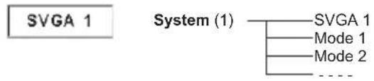
text_image
SVGA 1 System (1) SVGA 1 Mode 1 Mode 2 ....* Systems displayed in the System Menu vary depending on an input signal.
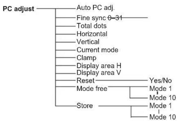
flowchart
graph TD
    A["PC adjust"] --> B["Auto PC adj."]
    B --> C["Fine sync 0-31"]
    C --> D["Total dots"]
    D --> E["Horizontal"]
    E --> F["Vertical"]
    F --> G["Current mode"]
    G --> H["Clamp"]
    H --> I["Display area H"]
    I --> J["Display area V"]
    J --> K["Reset"]
    K --> L["Yes/No"]
    K --> M["Mode free"]
    M --> N["Store"]
    N --> O["Mode 1"]
    N --> P["Mode 10"]
    N --> Q["Mode 1"]
    N --> R["Mode 10"]
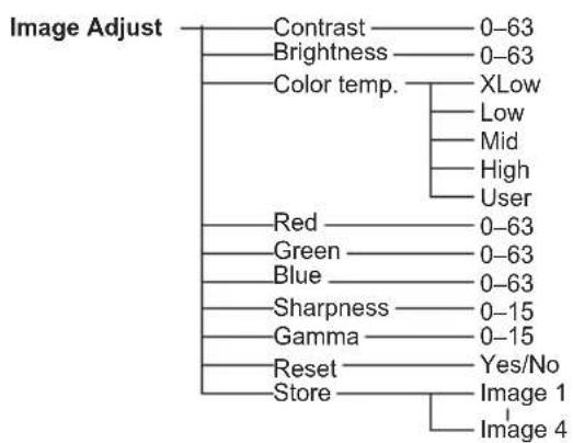
flowchart
graph TD
    A["Image Adjust"] --> B["Contrast"]
    A --> C["Brightness"]
    A --> D["Color temp."]
    D --> E["XLow"]
    D --> F["Low"]
    D --> G["Mid"]
    D --> H["High"]
    D --> I["User"]
    A --> J["Red"]
    A --> K["Green"]
    A --> L["Blue"]
    A --> M["Sharpness"]
    A --> N["Gamma"]
    A --> O["Reset"]
    A --> P["Store"]
    P --> Q["Image 1"]
    P --> R["Image 4"]
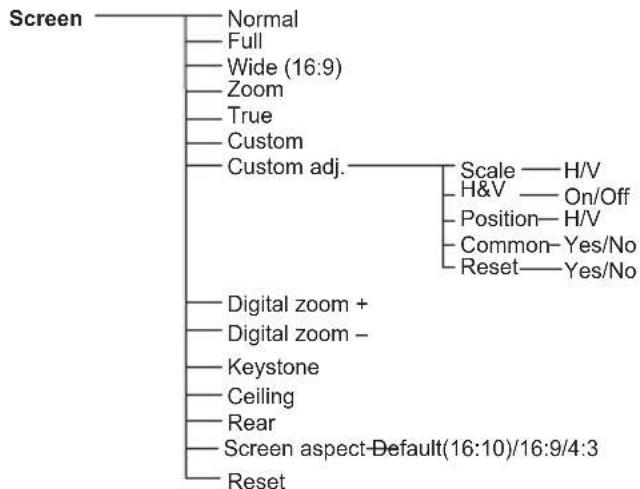
flowchart
graph TD
    A["Screen"] --> B["Normal"]
    B --> C["Full"]
    C --> D["Wide (16:9)"]
    D --> E["Zoom"]
    E --> F["True"]
    F --> G["Custom"]
    G --> H["Custom adj."]
    H --> I["Scale — H/V"]
    H --> J["H&V — On/Off"]
    H --> K["Position— H/V"]
    H --> L["Common— Yes/No"]
    H --> M["Reset — Yes/No"]
    H --> N["Digital zoom +"]
    H --> O["Digital zoom -"]
    H --> P["Keystone"]
    H --> Q["Ceiling"]
    H --> R["Rear"]
    H --> S["Screen aspect—Default(16:10)/16:9/4:3"]
    H --> T["Reset"]
Indicators and Projector Condition
Check the indicators for projector condition.
| Indicators | Projector Condition | ||
| POWER red/ green | WARNING red | LAMP REPLACE yellow | |
| [27X3] |  | [0C67] | The projector is off. (The AC power cord is unplugged.) |
 | [ATTW] | * | The projector is in stand-by mode. Press the ON/STAND-BY button to turn on the projector. |
 |  | * | The projector is operating normally. |
 |  | * | The projector is preparing for stand-by or the projection lamp is being cooled down. The projector cannot be turned on until cooling is completed and the POWER indicator stops blinking. |
| [064H] |  | * | The projector is in the Power management mode. |
| [2TT3] | [206H] | * | The temperature inside the projector is abnormally high. The projector cannot be turned on. When the projector is cooled down enough and the temperature returns to normal, the POWER indicator stops blinking and the projector can be turned on. (The WARNING indicator keeps blinking.) |
| [Y2DK] | [0CXC] | * | The projector has been cooled down enough and the temperature returns to normal. When turning on the projector, the WARNING indicator stops blinking. |
 | [Y2BD] | * | The projector detects an abnormal condition and cannot be turned on. Unplug the AC power cord and plug it again to turn on the projector. If the projector is turned off again, unplug the AC power cord and contact the dealer or the service center for service and checkup. Do not leave the projector on. It may cause an electric shock or a fire hazard. |

• • • green
• • • red
•••off


• • • blinks green.

• • • blinks red.
When the projection lamp reaches its end of life, the LAMP REPLACE indicator lights yellow. When this indicator lights yellow, replace the projection lamp with a new one promptly. (p. 65)
Compatible Computer Specifications
Basically this projector can accept the signal from all computers with the V-, H-Frequency mentioned below and less than 140 MHz of Dot Clock.
When selecting these modes, PC adjustment can be limited.
| ON-SCREEN DISPLAY | RESOLUTION | H-Freq. (KHz) | V-Freq. (Hz) | ON-SCREEN DISPLAY | RESOLUTION | H-Freq. (KHz) | V-Freq. (Hz) |
| VGA 1 640 | x 480 31.47 59.88 | SXGA 5 1280 x 1024 | 63.74 60.01 | ||||
| VGA 2 720 | x 400 31.47 70.09 | SXGA 6 1280 x 1024 | 71.69 67.19 | ||||
| VGA 3 640 | x 400 31.47 70.09 | SXGA 7 1280 x 1024 | 81.13 76.107 | ||||
| VGA 4 640 | x 480 37.86 74.38 | SXGA 8 1280 x 1024 | 63.98 60.02 | ||||
| VGA 5 640 | x 480 37.86 72.81 | SXGA 9 1280 x 1024 | 79.976 75.025 | ||||
| VGA 6 640 | x 480 37.50 75.00 | SXGA 10 1280 x 960 | 60.00 60.00 | ||||
| VGA 7 640 | x 480 43.269 85.00 | SXGA 11 1152 x 900 61.20 65.20 | |||||
| MAC LC13 | 640 x 480 34.97 66.60 | SXGA 12 1152 x 900 71.40 75.60 | |||||
| MAC 13 640 | x 480 35.00 66.67 | SXGA 13 1280 x 1024 50.00 | 86.00 (Interface) | ||||
| 480p | 640 x 480 31.47 59.88 | SXGA 14 1280 x 1024 | 50.00 | 94.00 (Interface) | |||
| 575p | 768 x 575 31.25 50.00 | SXGA 15 1280 x 1024 | 63.37 60.01 | ||||
| 480i 640 | x 480 15.734 | 60.00 (Interface) | SXGA 16 1280 x 1024 | 76.97 72.00 | |||
| 575i | 768 x 576 | 15.625 | 50.00 (Interface) | SXGA 17 1152 x 900 | 61.85 66.00 | ||
| SVGA 1 800 | x 600 35.156 56.25 | SXGA 18 1280 x 1024 46.43 | 86.70 (Interface) | ||||
| SVGA 2 800 | x 600 37.88 60.32 | SXGA 19 | 1280 x 1024 | 63.79 60.18 | |||
| SVGA 3 800 | x 600 46.875 75.00 | SXGA 20 | 1280 x 1024 91.146 85.024 | ||||
| SVGA 4 800 | x 600 | 53.674 | 85.06 | SXGA+ 1 | 1400 x 1050 63.97 60.19 | ||
| SVGA 5 800 | x 600 48.08 72.19 | SXGA+ 2 | 1400 x 1050 | 65.35 60.12 | |||
| SVGA 6 800 | x 600 37.90 61.03 | SXGA+ 3 | 1400 x 1050 65.12 59.90 | ||||
| SVGA 7 800 | x 600 34.50 55.38 | MAC21 1152 x 870 68.68 75.06 | |||||
| SVGA 8 800 | x 600 38.00 60.51 | MAC 1280 x 960 75.00 75.08 | |||||
| SVGA 9 800 | x 600 38.60 60.31 | MAC 1280 x 1024 80.00 75.08 | |||||
| SVGA 10 800 | x 600 32.70 51.09 | WXGA 1 | 1366 x 768 48.36 | 60.00 | |||
| SVGA 11 800 | x 600 38.00 60.51 | WXGA 2 1360 x 768 | 47.70 60.00 | ||||
| MAC 16 832 | x 624 49.72 74.55 | WXGA 3 | 1376 x 768 | 48.36 60.00 | |||
| MAC 19 1024 | x 768 60.24 75.08 | WXGA 4 1360 x 768 | 56.16 72.00 | ||||
| XGA 1 1024 | x 768 | 48.36 60.00 | WXGA 6 | 1280 x 768 47.776 59.87 | |||
| XGA 2 1024 | x 768 68.677 84.997 | WXGA 7 1280 x 768 | 60.289 74.893 | ||||
| XGA 3 1024 | x 768 60.023 75.03 | WXGA 8 1280 x 768 | 68.633 84.837 | ||||
| XGA 4 1024 | x 768 | 56.476 70.07 | WXGA 9 | 1280 x 800 49.600 60.050 | |||
| XGA 5 1024 | x 768 60.31 74.92 | WXGA 10 | 1280 x 800 | 41.200 50.000 | |||
| XGA 6 1024 | x 768 | 48.50 60.02 | WXGA 11 | 1280 x 800 49.702 59.810 | |||
| XGA 7 1024 | x 768 | 44.00 54.58 | WXGA 12 | 1280 x 800 | 63.98 60.02 | ||
| XGA 8 1024 | x 768 | 63.48 79.35 | WUXGA 1 | 1920 x 1200 74.556 | 59.885 | ||
| XGA 9 | 1024 x 768 | 36.00 | 87.17 (Interface) | WUXGA 2 | 1920 x 1200 | 74.038 59.950 | |
| XGA 10 1024 | x 768 | 62.04 77.07 | WSXGA+ 1 | 1680 x 1050 | 65.290 59.954 | ||
| XGA 11 1024 | x 768 | 61.00 75.70 | WXGA+ 1 | 1440 x 900 55.935 59.887 | |||
| XGA 12 1024 | x 768 | 35.522 | 86.96 (Interface) | WXGA+ 2 | 1440 x 900 | 74.918 60.000 | |
| XGA 13 1024 | x 768 | 46.90 58.20 | UXGA 1 1600 x 1200 | 75.00 60.00 | |||
| XGA 14 1024 | x 768 | 47.00 58.30 | UXGA 2 1600 x 1200 | 81.25 65.00 | |||
| XGA 15 1024 | x 768 | 58.03 72.00 | UXGA 3 1600 x 1200 | 87.5 70.00 | |||
| SXGA 1 | 1152 x 864 | 64.20 70.40 | UXGA 4 1600 x 1200 93.75 75.00 | ||||
| SXGA 2 | 1280 x 1024 62.50 58.60 | 720p 1280 x 720 | 45.00 60.00 | ||||
| SXGA 3 1280 | x 1024 63.90 60.00 | 720p 1280 x 720 | 37.50 50.00 | ||||
| SXGA 4 1280 | x 1024 | 63.34 59.98 | 1035i 1920 x 1035 | 33.75 | 60.00 (Interface) | ||
√Note:
The specifications are subject to change without notice.
When the input signal is digital from HDMI terminal, refer to the chart below.
| ON-SCREEN DISPLAY | RESOLUTION | H-Freq. (KHz) | V-Freq. (Hz) |
| D-480p 640 | × 480 31.47 59.88 | ||
| D-575p 768 | × 575 31.25 50.00 | ||
| D-720p 1280 | × 720 37.50 50.00 | ||
| D-720p 1280 | × 720 45.00 60.00 | ||
| D-VGA 640 | × 480 31.47 59.94 | ||
| D-SVGA 800 | × 600 37.879 60.32 | ||
| D-XGA 1024 | × 768 43.363 60.00 | ||
| D-WXGA 1 | 1366 × 768 | 48.36 60.00 | |
| D-WXGA 2 | 1360 × 768 47.7 | 60.00 | |
| D-WXGA 3 | 1376 × 768 48.36 60.00 | ||
| D-WXGA 4 | 1360 × 768 | 56.160 72.000 | |
| D-WXGA 5 | 1366 × 768 46.5 | 00 50.000 | |
| D-WXGA 6 | 1280 × 768 47.776 59.870 | ||
| D-WXGA 7 | 1280 × 768 60.289 74.893 | ||
| D-WXGA 8 | 1280 × 768 | 68.633 84.837 | |
| D-WXGA 9 | 1280 × 800 49.572 59.870 | ||
| D-1080i 1920 | × 1080 ---- | 59.94 (Interface) | |
| D-1080p | 1920 × 1080 ---- | 59.94 | |
| D-1080p | 1920 × 1080 ---- | 60.00 | |
| D-1080p | 1920 × 1080 ---- | 50.00 |
| ON-SCREEN DISPLAY | RESOLUTION | H-Freq. (KHz) | V-Freq. (Hz) |
| D-WXGA 10 | 1280 x 800 41.200 50.000 | ||
| D-WXGA 11 | 1280 x 800 49.702 59.810 | ||
| D-WXGA 12 | 1280 x 800 63.98 60.02 | ||
| D-SXGA1 1 | 280 x 1024 63.98 60.02 | ||
| D-SXGA2 1 | 280 x 1024 60.276 58.069 | ||
| D-SXGA3 1 | 280 x 1024 31.65 29.80 | ||
| D-SXGA+ 1 | 1400 x 1050 63.97 60.19 | ||
| D-SXGA+ 2 | 1400 x 1050 65.350 60.120 | ||
| D-SXGA+ 3 | 1400 x 1050 65.120 59.900 | ||
| D-UXGA | 1600 x 1200 75.00 60.00 | ||
| D-WSXGA +1 | 1680 x 1050 65.290 59.954 | ||
| D-WXGA +1 | 1440 x 900 55.935 59.887 | ||
| D-1035i 19 | 20 x 1035 | 33.75 | 60.00 (Interlace) |
| D-1080i 19 | 20 x 1080 | 33.75 | 60.00 (Interlace) |
| D-1080i 19 | 20 x 1080 | 28.125 | 50.00 (Interlace) |
| D-WUXGA 2 | 1920 x 1200 74.038 59.95 |
√ Note:
- The specifications are subject to change without notice.
- Depending on your PC settings, the digital signals of your PC may not be projected correctly. In such a case, confirm your PC settings.
- When you project a DVI signal, connect the cables, turn the projector on, then select the input. Finally, turn on your PC. Be sure to follow this procedure, otherwise an image may not be projected on the screen. If an image is not projected correctly, restart your PC.
- Do not disconnect the cable while the projector is running. If the cable has been disconnected and then reconnected, an image may not be correctly projected.
Technical Specifications
Mechanical Information
Projector Type Multi-media Projector
Dimensions (W x H x D) 13.78" x 3.44" x 10.02"
(350.0 mm X 87.5 mm X 254.4 mm )
(Not including protrusions)
Net Weight 7.51 lbs (3.4 kg)
Feet Adjustment 0° to 12°
Panel Resolution
LCD Panel System 0.59" TFT Active Matrix type, 3 panels
Panel Resolution 1,280 x 800 dots
Number of Pixels 3,072,000 (1,280 x 800 x 3 panels)
Signal Compatibility
Color System
SD/HD TV Signal
PAL, SECAM, NTSC, NTSC4.43, PAL-M, and PAL-N
Component: 480i, 480p, 575i, 575p, 720p, 1035i and 1080i
HDMI: 480p, 575p, 720p, 1080i and 1080p
H-sync. 15 KHz–100 kHz, V-sync. 50–100 Hz
Optical Information
Projection Image Size (Diagonal)
Throw Distance
Projection Lens
Adjustable from 30" to 300"
2.4' \~ 25.2' (0.74 m \~ 7.67 m)
F 1.65 \~ 2.33 lens with f 15.47 mm \~ 24.53 mm
with manual zoom and focus
Projection Lamp 245 W
Interface
Video Input Jack
S-video Input Jack
Audio Input Jacks
Computer 1/Computer 2 Audio Input Jacks
Computer In 1/Component Input Terminal
Computer In 2/Monitor Output Terminal
Control Port
Audio Output Jack
LAN Connection Terminal
HDMI
RCA Type x 1
Mini DIN 4 pin x 1
RCA Type x 2
Mini Jack (stereo) x 2
Mini D-sub 15 pin x 1
Mini D-sub 15 pin x 1
D-sub 9 pin x 1
Mini Jack (stereo) x 1 (variable)
RJ-45
HDMI (V.1.3 with Deep Color) x 1
Audio
Internal Audio Amp
Built-in Speaker
10 W RMS
1 speaker, ø1.5"(37 mm)
Power
Voltage and Power Consumption
AC 100–240 V (3.8-1.8 A Max.), 50/60 Hz
Operating Environment
Operating Temperature 41^ F– 95^ F ( 5^ C– 35^ C)
Storage Temperature
14^-140^ (-10^-60^)
Remote Control
Battery
Operating Range 16.4' (5 m)/±30°
Dimensions
Net Weight 2.37 oz (67 g) (including batteries)
AAA or LR03 1.5V ALKALINE TYPE x 2
2.0" (W) x 0.7" (H) x 4.3" (D) (52 mm x 18 mm x 110 mm)
Accessories
Owner's manual (CD-ROM) Network Application (CD-ROM) Quick Reference Guide AC Power Cord Remote control and Batteries VGA Cable Lens Cap with String PIN Code Label Soft Carrying Case Filter Cover for Ceiling Mount
- The specifications are subject to change without notice.
- LCD panels are manufactured to the highest possible standards. Even though 99.99% of the pixels are effective, a tiny fraction of the pixels (0.01% or less) may be ineffective by the characteristics of the LCD panels.
Optional Parts
The parts listed below are optionally available. When ordering those parts, specify the item name and Model No. to the sales dealer.
Model No.
COMPONENT-VGA cable : AH-98771
SCART-VGA cable : AH-98881
PJ Link Notice
This projector is compliant with PJLink Standard Class 1 of JBMIA (Japan Business Machine and Information System Industries Association). This projector supports all commands defined by PJLink Class 1 and is verified conformance with PJLink Standard Class 1.
For PJ Link password, see the owner's manual of "Network Set-up and Operation."
| Projector Input PJLink Input Parameter | |||
| Computer 1 RGB RGB 1 11 | |||
| RGB (Scart) RGB 2 12 | |||
| Computer 2 RGB RGB 3 13 | |||
| HDMI HDMI DIGITAL 3 33 | |||
| Video Video VIDEO 1 21 | |||
| S-video | S-video | VIDEO 5 25 | |
PJLink is a registered trademark of JBMIA and pending trademark in some countries.
PJLink™
Attaching the Filter Cover to the Projector
The supplied filter cover is designed for preventing dust accumulation on the filter when mounting the projector on the ceiling.
1 Turn over the projector.
2 Before attaching the filter cover to the projector, removing the filter cover (bottom) first. See page 61 for removing.
3 For attaching the filter cover to the projector, push the cover as the picture shown. (For removing the filter cover, push the cover to the opposite direction.)
4 Attach the projector to the ceiling mount in accordance with the instruction manuals which come with the ceiling mount.
To Ceiling Mount
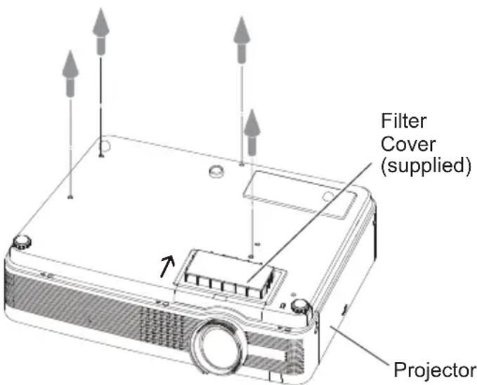
text_image
Filter Cover (supplied) Projector√ Note:
- Please keep the filter cover (bottom) for later use.
Configurations of Terminals
COMPUTER IN 1 / COMPONENT IN
Terminal: Analog RGB (Mini D-sub 15 pin)
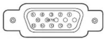
text_image
⑤ ④ ③ ② ① ⑩ ⑨878 ⑮ ⑬ ⑭ ⑫ ⑬| 1 | Red/Cr Input | 9 | +5V Power |
| 2 | Green/Y Input | 10 | Ground (Vert.sync.) |
| 3 | Blue/Cb Input | 11 | Ground |
| 4 | ---- | 12 | DDC Data |
| 5 | Ground (Horiz.sync.) | 13 | Horiz. sync. Input/Output (Composite H/V sync.) |
| 6 | Ground (Red) | 14 | Vert. sync. |
| 7 | Ground (Green) | 15 | DDC Clock |
| 8 | Ground (Blue) | ||
COMPUTER IN 2/MONITOR OUT (ANALOG)
Terminal: Analog RGB (Mini D-sub 15 pin)
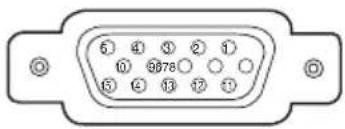
text_image
5 4 3 2 1 10 9678 15 4 13 12 11| 1 | Red Input/Output | 9 | ---- |
| 2 | Green Input/Output | 10 | Ground (Vert.sync.) |
| 3 | Blue Input/Output | 11 | ---- |
| 4 | ---- | 12 | ---- |
| 5 | Ground (Horiz.sync.) | 13 | Horiz. sync. Input/Output |
| 6 | Ground (Red) | 14 | Vert. sync. |
| 7 | Ground (Green) | 15 | ---- |
| 8 | Ground (Blue) | ||
HDMI (19 Pin Type A)
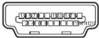
text_image
1 5 7 9 □ 11 13 5 7 9 2 4 6 8 □ □ □ 18 16 14 12 17| 1 | TMDS Data 2+ Input | 11 | Ground (TMDS Clock) |
| 2 | Ground (TMDS Data 2) | 12 | TMDS Clock- Input |
| 3 | TMDS Data 2- Input | 13 | ---- |
| 4 | TMDS Data 1+ Input | 14 | ---- |
| 5 | Ground (TMDS Data 1) | 15 | SCL |
| 6 | TMDS Data 1- Input | 16 | SDA |
| 7 | TMDS Data 0+ Input | 17 | Ground (DDC/CEC) |
| 8 | Ground (TMDS Data 0) | 18 | +5V Power |
| 9 | TMDS Data 0- Input | Plug insert detection19 | |
| 10 | TMDS Clock+ Input | ||
CONTROL PORT CONNECTOR (D-sub 9 pin)
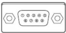
| Serial | |
| 1 | ---- |
| 2 | R X D |
| 3 | T X D |
| 4 | ---- |
| 5 | SG |
| 6 | ---- |
| 7 | ---- |
| 8 | ---- |
| ----9 |
LAN TERMINAL
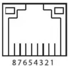
text_image
87654321| 1 | TX + |
| 2 | TX - |
| 3 | RX + |
| 4 | ---- |
| 5 | ---- |
| 6 | RX - |
| 7 | ---- |
| 8 | ---- |
List of Picture in Picture
o : Picture in Picture combinations are enabled.
x : Picture in Picture combinations are disabled.
√Note:
- When the input signal(s) is/are incompatible, X mark will be displayed on the Main/Sub picture.
- Depending on the frequency or signal type of PC/AV input, the display resolution lowered or images may not be displayed on the Main/Sub picture.
- Inputting PC analog signals: Between 100-140 MHz
- Inputting PC analog signals: More than 140 MHz
- Inputting PC digital signals: More than 100 MHz
- Inputting AV digital signals: 1080p
- Inputting signal formats: SXGA 20, WUXGA 1, WUXGA 2, WSXGA+1, WXGA+2, UXGA 1, UXGA 2, UXGA 3, UXGA 4, D-1080p
PIN code Number Memo
Write down the PIN code number in the column below and keep it with this manual securely. If you forgot or lost the number and unable to operate the projector, contact the service center.
PIN Code Lock No.
Factory default set No: 1 2 3 4*
Logo PIN Code Lock No.
Factory default set No: 4 3 2 1*
*Should the four-digit number be changed, the factory set number will be invalid.
While the projector is locked with the PIN code.
Put the label below (supplied) on in a prominent place of the projector's body while it is locked with a PIN code.
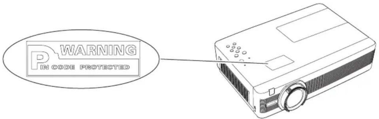
text_image
P/WARNING IN CODE PROTECTEDDimensions
Unit: mm(inch)

Screw Holes for Ceiling Mount
Screw: M4
Depth: 12.0(0.47)
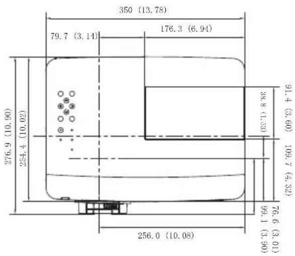
other
| Dimension | Value | | --------- | ----- | | Width | 350 (13.78) | | Height | 176.3 (6.94) | | Top Margin | 79.7 (3.14) | | Bottom Margin | 256.0 (10.08) | | Total Width | 276.9 (10.90) | | Total Height | 91.4 (3.60) | | Total Height | 109.7 (4.32) | | Total Height | 99.1 (3.90) | | Total Height | 76.6 (3.01) | | Total Height | 254.4 (10.02) | | Total Height | 254.2 (10.02) | | Total Height | 276.9 (10.90) |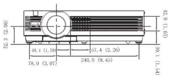
text_image
52.3 (2.06) 40.4 (1.59) 78.0 (3.07) 57.4 (2.26) 240.0 (9.45) 42.0 (1.65) 39.1 (1.54)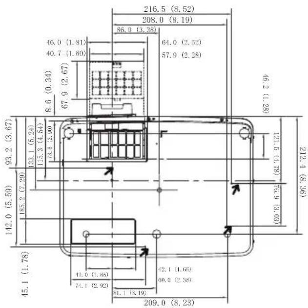
text_image
216.5 (8.52) 208.0 (8.19) 86.0 (3.38) 46.0 (1.81) 40.7 (1.60) 64.0 (2.52) 57.9 (2.28) 8.6 (0.34) 67.9 (2.67) 45.2 (1.28) 93.2 (3.67) 133.1 (5.24) 135.3 (4.54) 13.8 (2.90) 142.0 (5.59) 185.2 (7.29) 121.5 (7.78) 76.9 (3.03) 212.4 (8.36) 45.1 (1.78) 47.0 (1.85) 74.1 (2.92) 42.1 (1.65) 60.0 (2.38) 81.1 (3.19) 209.0 (8.23)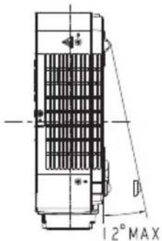
text_image
12° MAXEIKI
U.S.A.
EIKI International, Inc.
30251 Esperanza
Rancho Santa Margarita
CA 92688-2132
U.S.A.
Tel: 800-242-3454 (949)-457-0200
Fax: 800-457-3454 (949)-457-7878
E-Mail : usa@eiki.com
Lakeside Oasis Middle Ring Business Centre
Block 10. #16-07,
1628, Jin Sha Jiang Road,
Shanghai, 200333. China
Main Line : 86-21-3251-3993
Service Hot Line : 86-21-3251-3995
P.O. Box 156, 310 First St. - Unit 2,
Midland, ON, L4R 4K8, Canada
Tel: 800-563-3454 (705)-527-4084
Fax : 800-567-4069 (705)-527-4087
E-Mail : canada@eiki.com
Eastern Europe
EIKI CZECH SPOL. s.r.o.
Nad Cementárnou 1163/4a
Praha 4, Podolí
147 00
Czech Republic
Tel: +420 241 410 928
+420 241 403 095
Fax: +420 241 409 435
No. 3A-2C, 4th Floor, Jalan PJU 8/3A,
Perdana Business Centre,
Bandar Damansara Perdana,
47820 Petaling Jaya, Selangor
Malaysia
Tel : +603-7722-4362
Fax : +603-7722-4392
E-Mail : sales@eiki.my
Japan & Worldwide
EIKI Industrial Company Limited.
4-12 Banzai-Cho, Kita-Ku, Osaka,
530-0028 Japan
Tel : +81-6-6311-9479
Fax : +81-6-6311-8486
WorldWide Website http://www.eiki.com