
Shipman WSTA-VM250P - Satellite receiver MEGASAT - Free user manual and instructions
Find the device manual for free Shipman WSTA-VM250P MEGASAT in PDF.


User questions about Shipman WSTA-VM250P MEGASAT
0 question about this device. Answer the ones you know or ask your own.
Ask a new question about this device
Download the instructions for your Satellite receiver in PDF format for free! Find your manual Shipman WSTA-VM250P - MEGASAT and take your electronic device back in hand. On this page are published all the documents necessary for the use of your device. Shipman WSTA-VM250P by MEGASAT.
USER MANUAL Shipman WSTA-VM250P MEGASAT
natural_image
White MEGASAT satellite antenna device with no visible text or symbols on body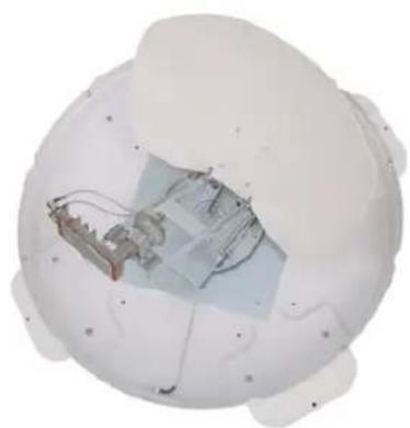
natural_image
Top-down view of a white spherical device with internal components and wiring (no visible text or symbols)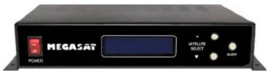
text_image
MEGASAT POWER MATELLITE SELECT RAGEAntenneneinheit
natural_image
Abstract geometric diagram with intersecting gray bars and a red vertical line (no text or symbols)Bad

natural_image
Abstract geometric shape with intersecting red and blue lines forming a cross (no text or symbols)Good

natural_image
Simple cross-shaped diagram with red and blue lines intersecting at center (no text or symbols)Best
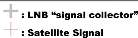
: LNB "Signal collector"
: Satellite Signal

LNB Center Line
text_image
(-) Direction (+) DirectionSkew Anpassung
7. Technische Daten
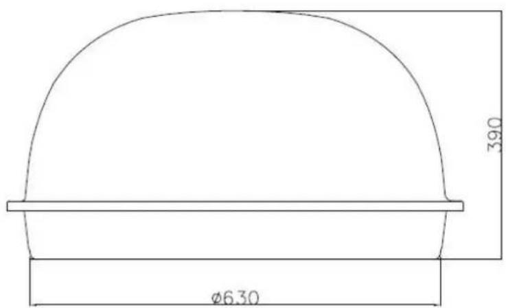
Durchmesser: ca. 68cm
Höhe: ca. 40cm
natural_image
White MEGASAT radar or satellite device with no visible text or symbols on the body or background1 Introduction
Specification....
Antenna System Overview......
Direct Broadcast Satellite Overview......
System Components......
2 Installation
Unpacking the Unit......
Preparing for the installation......
Selecting the location......
Equipment and cable installation......
Setting the LNB Skew Angle(Manual Skew version only)......
3 Operation
Receiving Satellite TV Signals......
Turning the System On/Off......
Changing Channels......
Watching TV......
Switching between Satellites......
Operating the IDU......
4 Troubleshooting
Simple Check....
Causes and Remedies......
1 Appendix A
How to set the skew angle......
2 Appendix B
Satellite Coverage Map......
3 Appendix C
Firmware Upgrade....
4 Appendix D
Antenna Drawing ....
Notes, Cautions, and Warnings

Caution – Improper handling by unqualified personnel can cause serious damage to this equipment. Unqualified personnel who tamper with this equipment may be held liable for any resultant damage to the equipment.
Install under DRY condition ONLY! Do not install this system in the rain, or under any wet conditions. Moisture may affect electronics and void warranty!

Warning – Need 2 people to install the antenna onto the roof. Do not try to install the antenna by yourself.
Note – Before you begin, carefully read each of the procedures in this manual. If you have not performed similar operations on comparable equipment, do not attempt to perform these procedures.
The satellite antenna system is the innovative and a technologically advanced satellite In-Motion system. The antenna has a unique combination of state-of-the-art components with the most sophisticated satellite acquisition and tracking programs to provide the following features:
■ Fast satellite acquisition
■ Compatible with any Satellite Receiver
■ Compatible with all Direct Broadcast Satellites (DBS)
■ Built-in Digital Broadcast Receiver(DVB)
■ Capable of High Definition receiving
Specification....
Antenna System Overview......
Direct Broadcast Satellite Overview......
System Components....
SpecificationSpecification
| Antenna Type Parabola | |
| Frequency Band Ku Band | |
| Radome Dimension 390x700mm | |
| Antenna Weight 9kg | |
| Antenna Gain 33dBi | |
| Minimum EIRP 49dBW | |
| Polarization V/H or RHCP/LHCP | |
| Type of Stabilization 2-Axis Step Motor | |
| Elevation Range 19° to 64° | |
| Azimuth Range | Unlimited |
| Tracking Rate | 50°/sec |
| Temperate Range | -20° to 70° |
| Power | 12~24VDC |
Table 1-1 Specification
Antenna System Overview Antenna System Overview
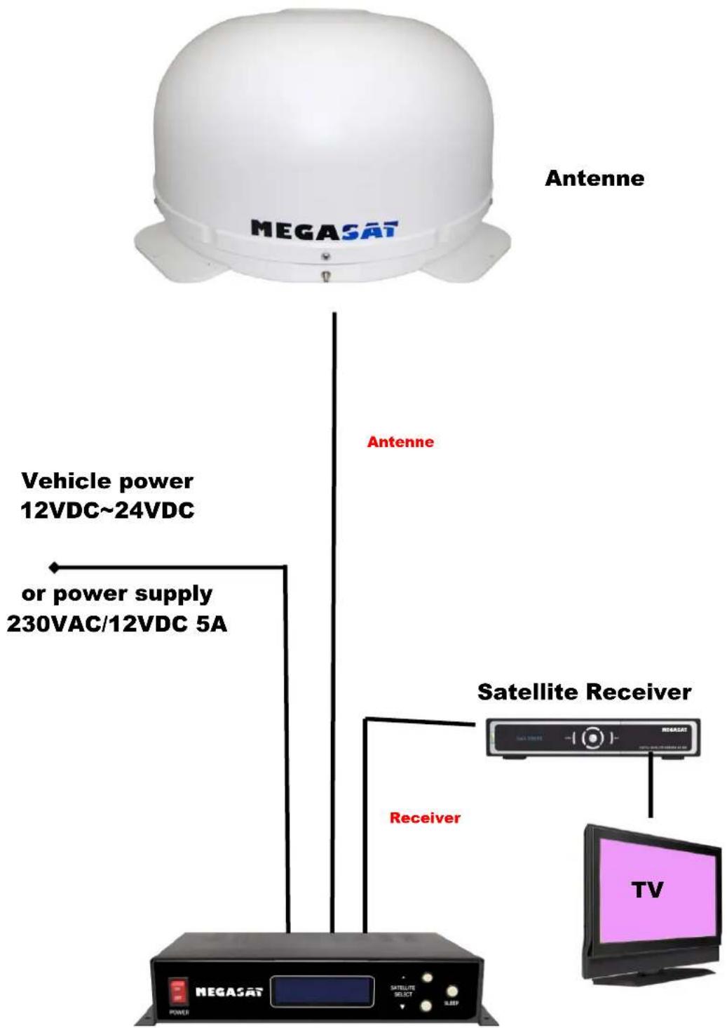
A complete satellite TV system, illustrated in Figure 1-1, includes the antenna connected to a IDU, a satellite TV receiver, and a television set.
text_image
Antenne MEGASAT Vehicle power 12VDC~24VDC or power supply 230VAC/12VDC 5A Antenne Satellite Receiver Receiver TV MEGASATDirect Broadcast Satellite Overview Direct Broadcast Satellite Overview
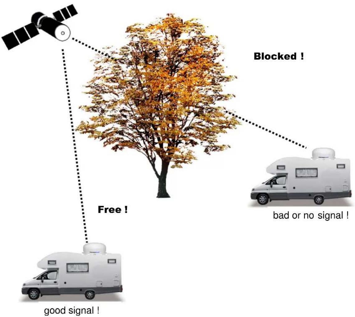
Direct Broadcast Service (DBS) satellites broadcast audio, video and data information from satellites located 22,000 miles in space. A receiving station, such as the antenna, should include a dish and satellite receiver to receive the signals and process them for use by the consumer audio and video equipment. The system requires a clear view of the satellite to maximize the signal reception.
flowchart
graph TD
    A["Satellite"] -->|Free!| B["RV Vehicle"]
    B -->|good signal!| C["RV Vehicle"]
    D["Blocked !"] -->|Good Signal!| E["RV Vehicle"]
    F["bad or no signal !"] -->|No Signal!| G["RV Vehicle"]
Figure 1-2 Satellite Blockage
Objects such as tall lighthouse, bridges and big ship that block this view will cause a loss of signal. The signal will be quickly restored once the antenna has a clear line of sight again. Heavy rain, cloud, snow or ice may also interfere with the signal reception quality. If the satellite signal is lost due to blockage or severe weather condition, services from the receiver will be lost (picture will freeze frame and may disappear). When the satellite signal strength is again high enough, then the receiver will resume providing desired programming services.
System ComponentsSystem Components
natural_image
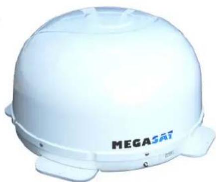
White MEGASAT helmet with visible branding and mounting feet (no text or symbols on the helmet itself)Antenna Unit
The antenna unit houses the antenna positioning mechanism, LNB (low noise block), and control elements within a radome. Weather tight connectors join the power, signal, and control cabling from the below deck units.
natural_image
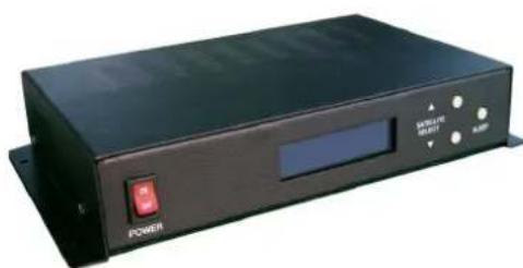
Exterior view of a black rectangular electronic device with a red indicator button and control panel (no readable text or symbols)IDU(InDoor Unit)
The IDU is the system's user interface, providing access to the system and its functions through an LCD and three buttons. The IDU also serves as the vessel's junction box, allowing the system to use vessel power, and supply and receive data to/from the antenna unit.
Figure 1-3 System Components
This section offers a general explanation of how properly to install the antenna. Installation of the antenna must be accomplished by or under the supervision of an authorized dealer for the Limited Warranty to be valid and in force. The steps in the installation and setup process are as follows:
Unpacking the unit Unpacking the unit
1. Open box and remove packing material.
The following items are included in the packaging of the antenna.
| Item | Description | Quantity |
| 1 | Antenna Unit | 1 each |
| 2 | IDU(In Door Unit) | 1 each |
| 3 | Power Cable | 1 each |
| 4 | Coaxial Cable (10m) | 1 each |
| 5 | Coaxial Cable (1m) | 1 each |
| 6 | User Manual | 1 set |
Table 2-1 Parts included
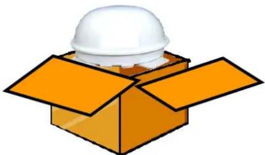
- Lift dome out of box vertically. Then lift unit out of box vertically. Do not turn box and "roll" out, or turn upside down to remove.

Lift Unit straight up out of the carton!
natural_image
Illustration of a white hard hat placed on an open orange cardboard box (no text or symbols)Figure 2-1 Unpacking the unit
Preparing for the InstallationPreparing for the installation
Install Tools and Materials
The antenna system is designed for simple installation and setup. However, the following list of equipment or items should be available during installation of the antenna.
■ Electric drill and drill bits
- Socket wrench
■ Silicon sealant
■ Fastener suitable for specific application
1. Verification of the Vessel's Power Supply.
- Confirm that the vessel's power supply is 12VDC\~24VDC.
2. Verification of the Satellite Receiver and IDU's attachment and the electricity supply
■ Attach Satellite Receiver and IDU in the interior of the vessel or the trunk.
■ Connect the power of Satellite Receiver and IDU.
■ Once the power of Satellite Receiver and IDU is verified, it confirms that both Satellite Receiver and IDU are working normally.
3. Procedure of the satellite's attachment and installation.
- Attach the satellite on the flat surface area of the vessel’s roof.
- Connect each end of the Coaxial antenna cable to the satellite's terminal and the IDU.
■ Connect the IDU and the Satellite Receiver box together through the coaxial cable.
■ Make sure that the satellite is working normally, once the power is supplied.

Warning : Things to consider when installing the antenna.
■ Turn off the power when attaching or detaching the antenna.
■ Make sure that the attached satellite is fixed on the flat surface.
■ When attaching, ensure that all the products are adhered properly.
■ Ensure that all the cables are connected properly.
Selecting the location
Determine the optimum mounting location for the antenna radome assembly. It should be installed where:
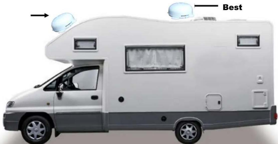
- The antenna has a clear line-of-sight view to as much of the sky as is practical. Choose a location where masts or other structures do not block the satellite signal from the dish as the vessel turns.
- The antenna is at least 5 feet away from other transmitting antennas (HF, VHF and radar) that may generate signals that may interfere with the antenna. The further away the antenna is from these other antennas, the less impact their operation will have on it.
- Direct radiation into the antenna from vessels radar, especially high power surveillance radar arrays, is minimized. The radome should be as far away from the vessels Radar as possible and should NOT be mounted on the same plane as the vessels Radar.
- The antenna radome assembly should be rigidly mounted to the vessel. If necessary, reinforce the mounting area to assure that it does not flex due to the vessel motion or vibration.
If these conditions cannot be entirely satisfied, the site selection will inevitably be a “best” compromise between the various considerations.
Perform a through site inspection on the roof for the antenna to be mounted.
- The antenna must have a clear view of the sky and the horizon at all the directions to avoid blockage of the satellite signal.
- The antenna should be on the top of the vehicle.
Poor
text_image
BestFigure 2-2 Selecting the location
Equipment and cable installation Equipment and cable installation
This offers a general explanation of how to install the IDU and satellite receiver properly to the inside of vessel connecting with coaxial cable.
- The Coaxial cable is routed from the antenna to the IDU inside the vessel.
- After Once deciding where to place the IDU and satellite receiver, make sure that both units are placed in a dry and protected area.
- The IDU and satellite receiver should be placed away from any heat source and in an area with proper ventilation.
-
Ensure that there are at least 3cm of space around both units for ventilation and connection of cables. Do not stack the units on top of each other.
-
The following describes the basic wiring configurations for the antenna system.
■ Connect the Coaxial cable to the antenna port on the back of the IDU
■ Connect one end of the supplied coaxial cable to the receiver port on the back of the IDU
■ Connect the other end of the coaxial cable to the satellite receiver
Setting the LNBS setting angle (Manual) (Manual)
natural_image
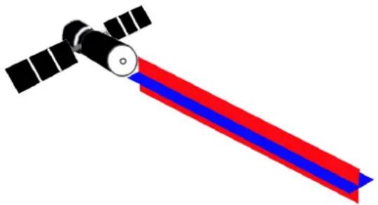
Illustration of a satellite with red and blue stripes (no text or symbols)Figure 2-3 Satellite signals
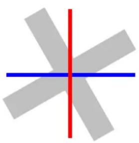
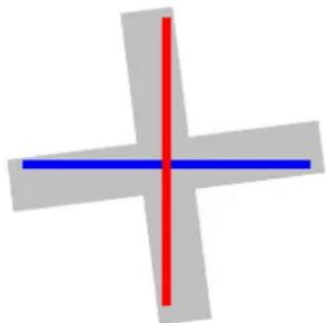
Signals transmitted in vertical(red) and horizontal(blue) wave offset exactly 90^ from each other. Since linear satellite signals are oriented in a precise cross pattern, Free Way 1S antenna's receiving element, called an LNB (low-noise block) must be oriented in the same way to optimize reception. This orientation adjustment is referred to as the LNB's “skew angle.” Figure 1-4 illustrates how skew determines the amount of signal the LNB collects. The more signal, the better reception.
natural_image
Abstract geometric diagram with intersecting gray bars and a red vertical line (no text or symbols)Bad
natural_image
Simple cross-shaped diagram with a red vertical line crossing a blue horizontal line (no text or symbols)Good

natural_image
Simple cross-shaped diagram with red vertical line and blue horizontal line (no text or symbols)Best
Figure 2-4 Best Skew Angle
text_image
+ : LNB "signal collector" + : Satellite SignalThe correct skew setting varies depending on your geographic location, since the orientation of your antenna to the satellite changes as you move. For complete details about adjusting the LNB's skew angle, see “Appendix A – How to Set the Skew Angle”

peration
The antenna system is easy to use. Under normal conditions, operation of the antenna requires no intervention from the user. Antenna unit initialization and satellite acquisition is completely automatic.
Receiving Satellite TV Signal....20
Turning the System On/Off....20
Changing Channels....21
Watching TV....21
Switching between Satellites....21
Operating the IDU....22
Receiving Satellite TV SignalsReceiving Satellite TV Signals
Television satellites are located in fixed positions above the Earth's equator and beam TV signals down to certain regions of the planet. To receive TV signals from a satellite, you must be located within that satellite's unique coverage area. To check it, see "Appendix B –
Satellite Coverage Map" In addition, since TV satellites are located above the equator, the antenna must have a clear view of the sky to receive satellite TV signals. Anything that stands between the antenna and the satellite can block the signal, resulting in lost reception.
Common causes of blockage include lighthouses, boat masts, trees, buildings, and bridges. Heavy rain, ice, or snow might also temporarily interrupt satellite signals.
Turning the System On/Off Turning the System On/Off
Since power to the antenna system is controlled by the IDU, you can turn the antenna on or off by applying/removing operating power to the IDU.
Turning on the System
Follow the steps below to turn on your antenna System.
- Make sure the antenna has a clear view of the sky.
-
Turn on your satellite TV receiver and TV.
-
Apply operating power to the IDU.
- Wait one minute for system startup. The IDU will display the Tracking Satellite screen after system testing is complete.
Turning off the System
Follow the steps below to turn off your antenna System.
- Remove operating power from the IDU.
- Turn off your satellite TV receiver and TV.
Changing ChannelsChanging Channels
If you have followed the installation instructions, your system should be set to the satellite of your choice and the system should have downloaded the appropriate channel guides. When the antenna system and satellite receiver is properly configured, it is easy to change the channel using the remote control that normally comes with the receiver unit.
Watching TVWatching TV
The antenna is designed to operate as efficiently and as reliably as possible when the vessel is moved and anchored. It is also the quickest satellite acquisition system available among the antennas. If you have anchored the vessel and the antenna has completed to searching selected satellite, turn off IDU Power to avoid unnecessary use of power. Because the LNB receives its power from the Satellite Receiver through the IDU, the antenna will continue to receive the satellite TV signals.
Switching between Satellites Switching between Satellites
You can switch between satellites using the IDU by pressing Satellite select buttons. Follow the steps below to switch to another satellite.
- Ensure that the LCD screen of the IDU is displayed.
HOTBIRD
ID: HOTHOTBIRD
ID: HOT
AUTO_SLP S:280
Figure 3-1 IDU LCD Screen
-
Press the Satellite select buttons to switch to another satellite.
-
The antenna shifts to track selected satellite. Wait for the Tracking Satellite screen to reappear with the ID of selected satellite displayed.
Operating the IDUOperating the IDU
Appearance
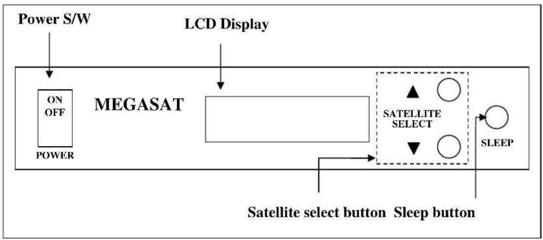
flowchart
graph TD
    A["Power S/W"] --> B["ON OFF POWER"]
    C["LCD Display"] --> D["MEGASAT"]
    D --> E["SATELLITE SELECT"]
    E --> F["Sleep button"]
    F --> G["SATellite select button"]
    G --> H["Satellite"]
Figure 3-2 Appearance of IDU
Functions of LCD Display
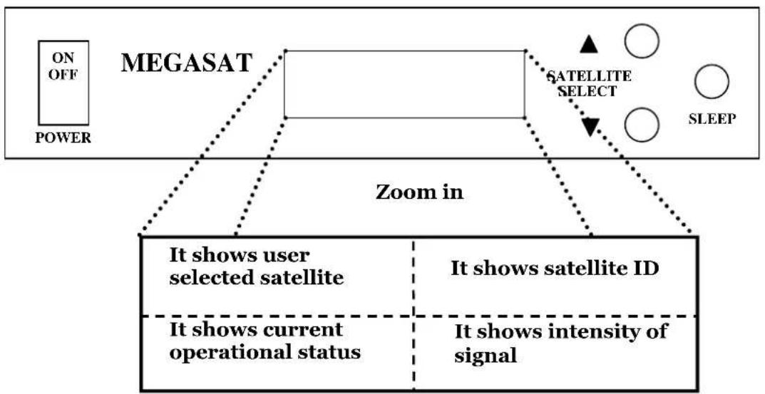
flowchart
graph TD
    A["ON OFF POWER"] --> B["MEGASAT"]
    B --> C["SATELLITE SELECT"]
    C --> D["SLEEP"]
    B --> E["Zoom in"]
    E --> F["It shows user selected satellite"]
    E --> G["It shows satellite ID"]
    E --> H["It shows current operational status"]
    E --> I["It shows intensity of signal"]
Figure 3-3 Functions of LCD Display
Explanation of words in LCD
- INIT : It shows condition of initializing the antenna.
- INIT-SCH : It shows condition of initial search mode.
- SAT-MOVE: It shows condition of moving to another satellite.
- S:xxx : It shows intensity of signal.
- ID:xxx : It shows ID of acquired satellite.
- GYRO-CAL : It shows condition of calibrating the Gyro Sensor.
General Operation Order
POWER

Information of IDU
Turn the power switch on.
LCD shows information of IDU.



Push the Satellite select buttons to choose satellite.
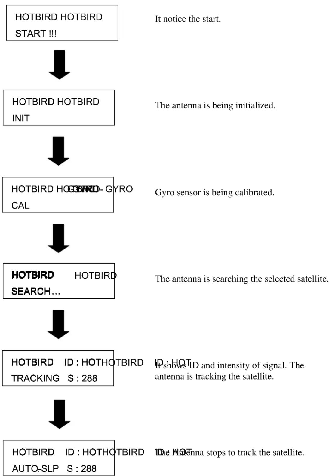
flowchart
graph TD
    A["HOTBIRD HOTBIRD START !!!"] --> B["HOTBIRD HOTBIRD INIT"]
    B --> C["HOTBIRD HOTBIRD-GYRO CAL"]
    C --> D["HOTBIRD SEARCH..."]
    D --> E["HOTBIRD ID: HOTHOTBIRD TRACKING S: 288"]
    E --> F["HOTBIRD ID: HOTHOTBIRD AUTO-SLP S: 288"]
    G["It notice the start."] --> B
    H["The antenna is being initialized."] --> B
    I["Gyro sensor is being calibrated."] --> C
    J["The antenna is searching the selected satellite."] --> D
    K["ID shows ID and intensity of signal. The antenna is tracking the satellite."] --> E
    L["The Antenna stops to track the satellite."] --> F
In case of search failure
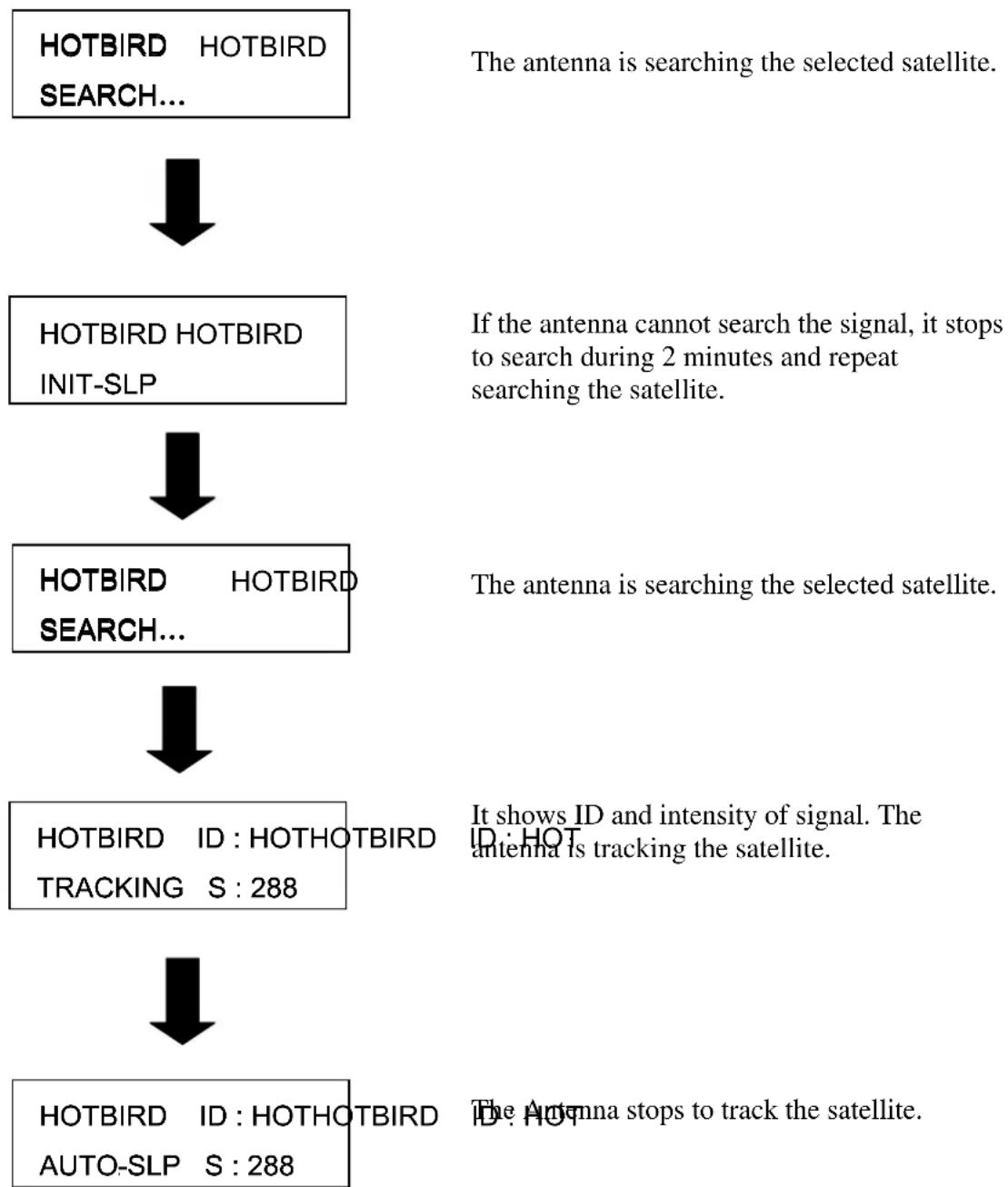
flowchart
graph TD
    A["HOTBIRD HOTBIRD SEARCH..."] --> B["HOTBIRD HOTBIRD INIT-SLP"]
    B --> C["HOTBIRD HOTBIRD SEARCH..."]
    C --> D["HOTBIRD ID : HOTHOTBIRD TRACKING S : 288"]
    D --> E["HOTBIRD ID : HOTHOTBIRD AUTO-SLP S : 288"]
    F["The antenna is searching the selected satellite."] --> G["If the antenna cannot search the signal, it stops to search during 2 minutes and repeat searching the satellite."]
    G --> H["The antenna is searching the selected satellite."]
    I["It shows ID and intensity of signal. The antenna is tracking the satellite."] --> J["The Antenna stops to track the satellite."]
There are a number of common issues that can affect the signal quality or the operation of the antenna system. The following sections address these issues and potential solutions.
Simple check....
Causes and Remedies......
Simple checkSimple check
Can the antenna see the satellite?
The antenna requires an unobstructed view of the sky to receive satellite TV signals. Common causes of blockage include trees, buildings, bridges, and mountains.
Is there excessive dirt or moisture on the antenna dome?
Dirt buildup or moisture on the dome can reduce satellite reception. Clean the exterior of the dome periodically.
Is it raining heavily?
Heavy rain or snow can weaken satellite TV signals. Reception should improve once the inclement weather subsides.
Is everything turned on and connected properly?
Make sure your TV and receiver are both turned on and set up for the satellite input. Finally, check any connecting cables to ensure none have come loose.
Is the antenna's LNB set to the correct skew angle? (Manual Skew Ver. Only)
To optimize reception, the antenna's LNB needs to be set to the correct skew angle for the satellite you want to track. See "Appendix A – How to set the skew angle" for details
Causes and Remedies Causes and Remedies
Receiver Fault
Your satellite TV receiver might be set up incorrectly or defective. First check the receiver's configuration to ensure it is set up for the desired programming. In the case of a faulty receiver, refer to your selected receiver's user manual for service and warranty information.
Satellite Coverage Issue
Television satellites are located in fixed positions above the Earth's equator and beam TV signals down to certain regions of the planet (not worldwide). To receive TV signals from a satellite, you must be located within that satellite's unique coverage area. See “Appendix-B Satellite Coverage Map”
Satellite Signal Blocked
The Antenna needs a clear line of sight (LOS), view to the satellite for uninterrupted reception. Objects such as tall lighthouse, bridges and big ship that block this view will cause a loss of signal. The signal will be quickly restored once the antenna has a clear line of sight again. Heavy rain, cloud, snow or ice may also interfere with the signal reception quality. If the satellite signal is lost due to blockage or severe weather condition, services from the receiver will be lost (picture will freeze frame and may disappear). When the satellite signal strength is again high enough, then the receiver will resume providing desired programming services.
Satellite Frequency Data Changed
If some channels work, while one or more other channels do not, or if the antenna cannot find the selected satellite, the satellite's frequency data might have changed. You can visit any WIWORLD-authorized dealer or distributor for assistance or visit http://www.wiworld.co.kr
Improper Wiring
If the system has been improperly wired, the antenna will not operate correctly. Refer to the User Manual for complete system wiring information or visit website (http://www.wiworld.co.kr)
Loose Cable Connectors
We recommend periodically checking the antenna unit's cable connections. A loose cable connector can reduce signal quality or prevent automatic satellite switching using the receiver's remote control. Fasten the cable connector.
Appendix A
How to Set up the Skew Angle
Signals transmitted in vertical and horizontal wave offset exactly 90^0 from each other. Since linear satellite signals are oriented in a precise cross pattern, the antenna's receiving element, called an LNB (low-noise block) must be oriented in the same way to optimize reception. This orientation adjustment is referred to as the LNB's “skew angle.” The correct skew setting varies depending on your geographic location, since the orientation of your antenna to the satellite changes as you move. This appendix provides how to set up the skew angle.
European Position Gridpean Position Grid
If you wish to determine the Skew Angle(LNB), use the position grid(Figure A-1 European Position Grid) and table(TableA-1 Regional Skew angle).
| 1 | 2 | 3 | 4 | 5 |
| 6 | 7 | 8 | 9 | 10 |
| 11 | 12 | 13 | 14 | 15 |
| 16 | 17 | 18 | 19 | 20 |
| 21 | 22 | 23 | 24 | 25 |
Figure A-1 Europe Position Grid
If you wish to set the correct skew, see "TableA-1 Regional Skew angle". The correct skew setting varies depending on your geographic location, since the orientation of your antenna to the satellite changes as you move.
If you have determine the correct skew angle, follow the steps below to adjust the antenna's LNB skew angle.

Caution - To avoid bodily injury, be sure to turn off the antenna and disconnect power to all wore components.
-
Turn off the antenna and disconnect power to all wired components.
-
Using the screwdriver, remove the screws securing the radome. Then remove and set it aside in a safe place.
Figure A-2 The Back of the Reflector
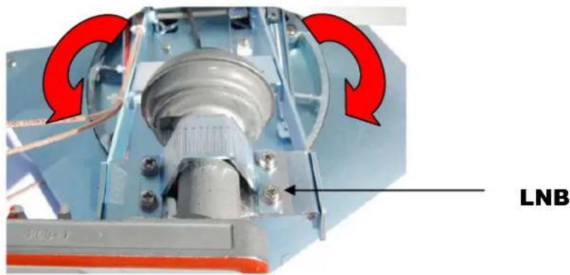
text_image
LNB-
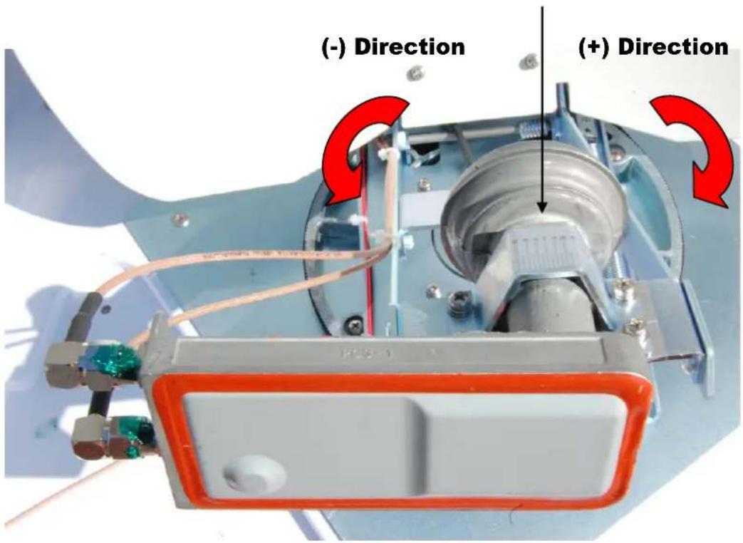
Loosen the four screws fastening the LNB.
-
Adjust the LNB clockwise or counter-clockwise, until the skew arrow on the LNB points to the skew angle that you determined earlier.
LNB Center Line
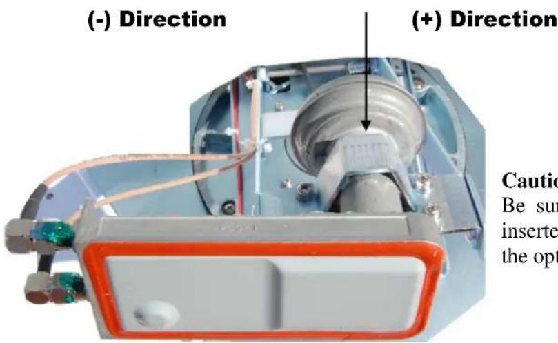
text_image
(-) Direction (+) Direction Caution Be sun inserted the opt
Caution
Be sure to keep the LNB fully inserted into the hall to ensure the optimum performance.
Figure A-3 LNB Skew Angle Adjustment
-
Tighten the four screws.
-
Reinstall the radome.
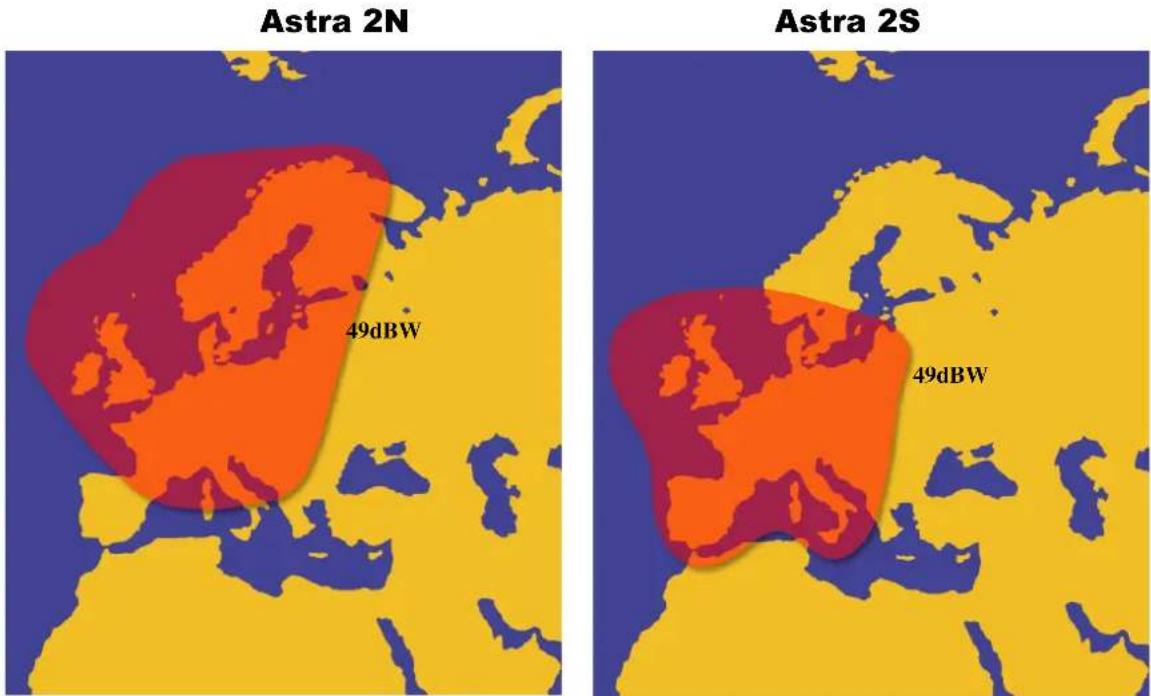
Appendix B Satellite Coverage Map
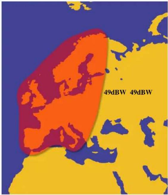
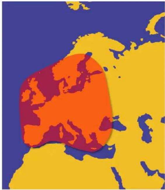
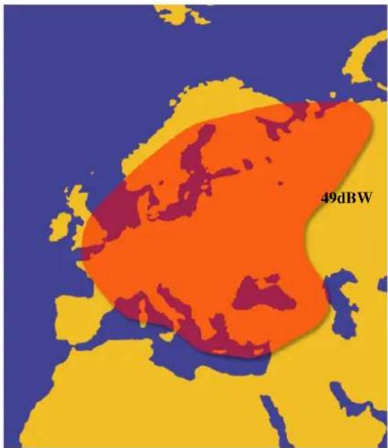
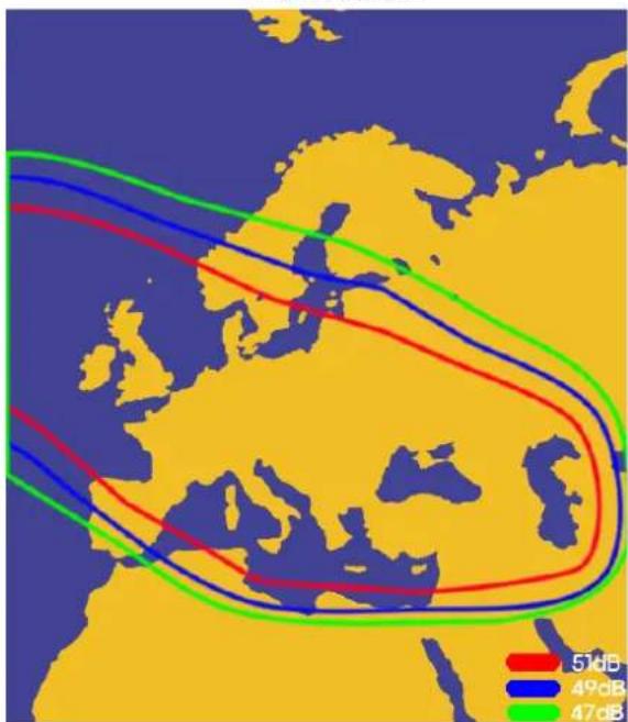
Television satellites are located in fixed positions above the Earth's equator and beam TV signals down to certain regions of the planet (not worldwide). To receive TV signals from a satellite, you must be located within that satellite's unique coverage area.
Satellite Coverage MapSatellite Coverage Map
Satellite TV broadcast spot beams are aimed at land masses where the bulk of subscribers can be found. Thus, the signal strength decreases as you travel away from the land masses. The further you travel offshore you will require a larger size antenna. Although this information is believed to be correct, WIWORLD Technologies has no control over the variations on the actual satellite footprint coverage. Signal strength and reception can be affected by the weather conditions.
text_image
Astra 2N 49dBW Astra 2S 49dBWFigure B-1 Astra 2N Coverage Map Figure B-2 Astra 2S Coverage Map
Astra 1
Hotbird
text_image
49dBW 49dBWFigure B-3 Astra 1 Coverage Map
natural_image
Color-coded map of Europe showing a large orange region surrounded by yellow and blue continents (no text or labels)Figure B-4 Hotbird Coverage Map
Astra 4
Thor 2/3
text_image
49dBWFigure B-5 Sirius Coverage Map
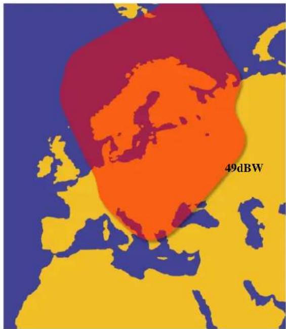
text_image
49dBWFigure B-6 Thor 2/3 Coverage Map
Atlantic Bird 3
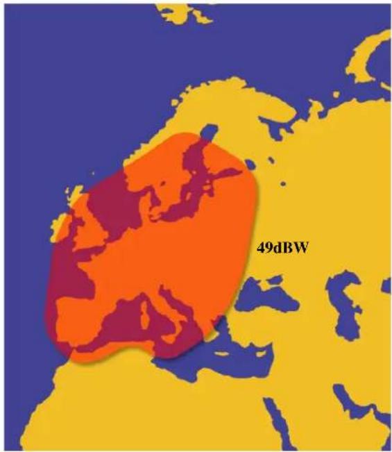
text_image
49dBWFigure B-7 Atlantic bird 3
Hispasat
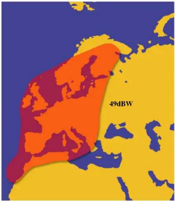
text_image
49dBWFigure B-8 Astra 2S Coverage Map
ASTRA 3
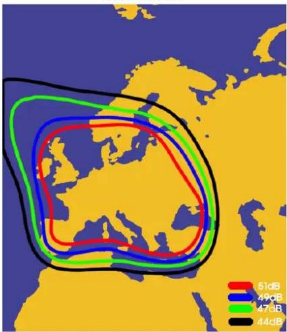
text_image
51dB 49dB 47dB 44dBTURKSAT
text_image
51dB 49dB 47dBAppendix C
Firmware Upgrade
If satellite beam is changed or eliminated, you have to upgrade firmware of IDU.
Firmware Upgrade
If antenna cannot search the selected satellite or move incorrectly, you need to change the firmware of IDU. To upgrade the firmware, follow the steps below.
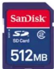
- Prepare the SD memory card.
text_image
SanDisk® SD Card 512MBFigure C-1 SD memory card
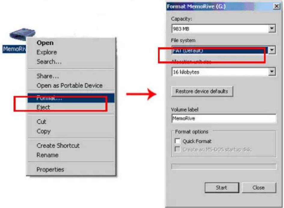
- Before you use the SD memory card, you should format it to "FAT16(Default)"
text_image
Open Explore Search... Share... Open as Portable Device Format... Eject Cut Copy Create Shortcut Rename Properties Format MemoRive (G) Capacity: 983 MB File system FAT (Default) Allocation unit size: 16 kilobytes Restore device defaults Volume label MemoRive Format options Quick Format Create an MS-DOS startup disk Start CloseFigure C-2 Formatting SD memory card
- After formatting your SD card, copy the new software file.
- Turn off the IDU.
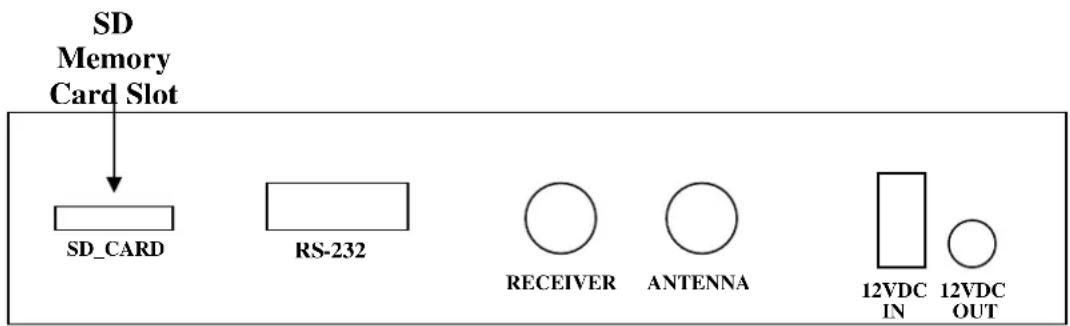
- Put your SD memory card into the SD slot of back side of the IDU.
text_image
SD Memory Card Slot SD_CARD RS-232 RECEIVER ANTENNA 12VDC IN 12VDC OUT- Turn on the IDU. You can see the message "WRITING SOFTWARE" in LCD Display.
WRITING WRITING
SOFTWARE
Figure C-4 Writing software
- If you see the message “FINISH TO WRITE”, IDU is finishing the software upgrade. You have to wait until the IDU is restarted.
FINISH TO WRITE FINISH TO WRITE
Figure C-5 Finishing to write
- Turn off the IDU. Take your SD memory card away from the IDU.
- Turn on the IDU.
Appendix D
Antenna Drawing
text_image
Ø6.30 390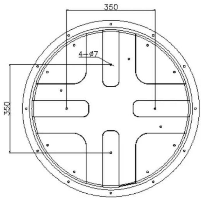
text_image
350 4-Ø7 350Figura C-1
Megasat
Industriestrasse 4a
Safety Data Sheet according to (EC) No 1907/2006
Page 1 of 6
TEROSTAT MS 939 WHITE DK310M
sds no.: 268236
V003.4
Revision: 11.07.2011
printing date: 12.07.2011
SECTION 1: Identification of the substance/mixture and of the company/undertaking
Product identifier:
TEROSTAT MS 939 WHITE DK310M
Relevant identified uses of the substance or mixture and uses advised against:
Intended use:
1-Component sealant
Details of the supplier of the safety data sheet:
Henkel AG & Co. KGaA
Henkelstr. 67
40191 Düsseldorf
Germany
Phone: +49 (211) 797-0
ua-productsafety.de@henkel.com
Emergency telephone number:
The Henkel information service also provides an around-the-clock telephone service on phone no.+49-(0)211-797-3350 for exceptional cases.
SECTION 2: Hazards identification
Classification of the substance or mixture:
Classification (CLP):
No data available.
Classification (DPD):
The product is not subject to classification according to the calculation methods of the "General Classification Guideline for Preparations of the EC" as issued in the last version.
Label elements (CLP):
No data available.
Label elements (DPD):
No classification required.
Other hazards:
None if used properly.
SECTION 3: Composition/information on ingredients
General chemical description:
Sealant
Base substances of preparation:
Silane-modified polyether
Declaration of the ingredients according to CLP (EC) No 1272/2008:
No data available.
Declaration of ingredients according to DPD (EC) No 1999/45:
| Hazardous components CAS-No. | EC Number REACH-Reg No. | content | Classification |
| Trimethoxyvinylsilane 2768-02-7 | 220-449-8 | < 5 % | Xn - Harmful; R10, R20 |
For full text of the R-Phrases indicated by codes see section 16 'Other Information'.
Substances without classification may have community workplace exposure limits available.
SECTION 4: First aid measures
Description of first aid measures:
General information:
If adverse health effects develop seek medical attention.
Inhalation:
Move to fresh air, consult doctor if complaint persists.
Skin contact:
Rinse with running water and soap. Apply replenishing cream. Change all contaminated clothing.
Eye contact:
Rinse immediately with plenty of running water (for 10 minutes). Seek medical attention if necessary.
Ingestion:
Rinse mouth, drink 1-2 glasses of water, do not induce vomiting, consult a doctor.
Most important symptoms and effects, both acute and delayed:
No particular measures required.
Indication of any immediate medical attention and special treatment needed:
No particular measures required.
SECTION 5: Firefighting measures
Extinguishing media:
Suitable extinguishing media:
All common extinguishing agents are suitable.
Extinguishing media which must not be used for safety reasons:
High pressure waterjet
Special hazards arising from the substance or mixture:
In the event of a fire, carbon monoxide (CO) and carbon dioxide (CO2) can be released.
Advice for firefighters:
Wear protective equipment.
Wear self-contained breathing apparatus.
SECTION 6: Accidental release measures
Personal precautions, protective equipment and emergency procedures: Wear protective equipment.
Environmental precautions: Do not empty into drains / surface water / ground water.
Methods and material for containment and cleaning up: Remove mechanically. Dispose of contaminated material as waste according to Chapter 13.
Reference to other sections: See advice in chapter 8
SECTION 7: Handling and storage
Precautions for safe handling:
Hygiene measures: Do not eat, drink or smoke while working. Wash hands before work breaks and after finishing work.
Conditions for safe storage, including any incompatibilities: Ensure good ventilation/extraction. Temperatures between + 10 °C and + 25 °C
Specific end use(s): 1-Component sealant
SECTION 8: Exposure controls/personal protection
Control parameters: None
Exposure controls:
Engineering controls: Ensure good ventilation/extraction.
Respiratory protection: Suitable breathing mask when there is inadequate ventilation.
Hand protection: Chemical-resistant protective gloves (EN 374). Suitable materials for short-term contact or splashes (recommended: at least protection index 2, corresponding to >30 minutes permeation time as per EN 374): Polychloroprene (CR; >=1 mm thickness) or natural rubber (NR; >=1 mm thickness) Suitable materials for longer, direct contact (recommended: protection index 6, corresponding to >480 minutes permeation time as per EN 374): Polychloroprene (CR; >=1 mm thickness) or natural rubber (NR; >=1 mm thickness) This information is based on literature references and on information provided by glove manufacturers, or is derived by analogy with similar substances. Please note that in practice the working life of chemical-resistant protective gloves may be considerably shorter than the permeation time determined in accordance with EN 374 as a result of the many influencing factors (e.g. temperature). If signs of wear and tear are noticed then the gloves should be replaced.
Eye protection: Protective goggles
Skin protection: Wear protective equipment.
Advices to personal protection equipment: Use only personal protection that's CE-labelled according to the regulation no. 819 of 19 August 1994.
SECTION 9: Physical and chemical properties
| Information on basic physical and chemical properties: | |
| Appearance | solid material |
| pasty | |
| white | |
| Odor | characteristic |
| pH | No data available / Not applicable |
| Initial boiling point | No data available / Not applicable |
| Flash point | >100 °C (>212 °F) |
| Decomposition temperature | No data available / Not applicable |
| Vapour pressure | No data available / Not applicable |
| Density(20 °C (68 °F)) | 1,50 g/cm3 |
| Bulk density | No data available / Not applicable |
| Viscosity(; 20 °C (68 °F)) | 200 - 300 pa.s |
| Viscosity (kinematic) | No data available / Not applicable |
| Explosive properties | No data available / Not applicable |
| Solubility (qualitative)(20 °C (68 °F); Solvent: Water) | Insoluble |
| Solubility (qualitative) | Insoluble |
| Solidification temperature | No data available / Not applicable |
| Melting point | No data available / Not applicable |
| Flammability | No data available / Not applicable |
| Auto-ignition temperature | No data available / Not applicable |
| Explosive limits | No data available / Not applicable |
| Partition coefficient: n-octanol/water | No data available / Not applicable |
| Evaporation rate | No data available / Not applicable |
| Vapor density | No data available / Not applicable |
| Solid content(105 °C ) | 98 % |
| Oxidising properties | No data available / Not applicable |
| Other information: | |
| No data available / Not applicable | |
SECTION 10: Stability and reactivity
| Reactivity: None if used for intended purpose. |
| Chemical stability: Stable under recommended storage conditions. |
| Possibility of hazardous reactions: See section reactivity |
| Conditions to avoid: None if used for intended purpose. |
| Hazardous decomposition products: No decomposition if used according to specifications. |
SECTION 11: Toxicological information
| General toxicological information:To the best of our knowledge no harmful effects are to be expected if the product is handled and used properly. |
SECTION 12: Ecological information
General ecological information:
The preparation is classified based on the conventional method outlined in Article 6(1)(a) of Directive 1999/45/EC. Relevant available health/ecological information for the substances listed under Section 3 is provided in the following.
Do not empty into drains, soil or bodies of water.
Toxicity:
| Hazardous components CAS-No. | Value type | Value | Acute Toxicity Study | Exposure time | Species | Method |
| Trimethoxyvinylsilane 2768-02-7 | LC50 | 191 mg/l | Fish | 96 h | Oncorhynchus mykiss | OECD Guideline 203 (Fish, Acute Toxicity Test) |
| Trimethoxyvinylsilane 2768-02-7 | EC50 | >100 mg/l | Daphnia | 48 h | Daphnia magna | OECD Guideline 202 (Daphnia sp. Acute Immobilisation Test) |
| Trimethoxyvinylsilane 2768-02-7 | EC50 | >100 mg/l | Algae | 72 h | OECD Guideline 201 (Alga, Growth Inhibition Test) |
SECTION 13: Disposal considerations
Waste treatment methods:
Product disposal:
The valid EEC waste code numbers are not product-related but are largely source-related. These can be requested from the manufacturer.
In consultation with the responsible local authority, must be subjected to special treatment.
SECTION 14: Transport information
General information:
Not hazardous according to RID, ADR, ADNR, IMDG, IATA-DGR.
SECTION 15: Regulatory information
Safety, health and environmental regulations/legislation specific for the substance or mixture:
VOC content
0%
(VOCV 814.018 VOC regulation
CH)
VOC Paints and Varnishes (EU):
This product is not a subject of the Directive 2004/42/EC
National regulations/information (Germany):
WGK:
- slightly water-endangering product. (German VwVwS of July 27, 2005)
Classification in conformity with the calculation method
Storage class VCI:
11
MSDS-No.: 268236
V003.4
TEROSTAT MS 939 WHITE DK310M
SECTION 16: Other information
The labelling of the product is indicated in Section 2. The full text
of all abbreviations indicated by codes in this safety data sheet are as follows:
R10 Flammable.
R20 Harmful by inhalation.
Further information:
This information is based on our current level of knowledge and relates to the product in the state in which it is delivered. It is intended to describe our products from the point of view of safety requirements and is not intended to guarantee any particular properties.