
IR 40 - Heating Heylo - Free user manual and instructions
Find the device manual for free IR 40 Heylo in PDF.


User questions about IR 40 Heylo
0 question about this device. Answer the ones you know or ask your own.
Ask a new question about this device
Download the instructions for your Heating in PDF format for free! Find your manual IR 40 - Heylo and take your electronic device back in hand. On this page are published all the documents necessary for the use of your device. IR 40 by Heylo.
USER MANUAL IR 40 Heylo
Translation of the original instruction manual
natural_image
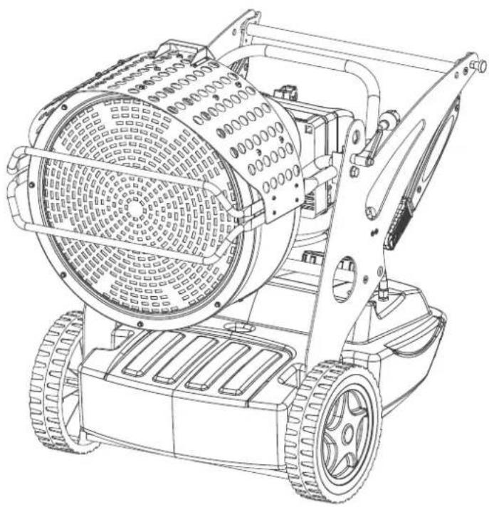
Technical line drawing of a tracked robotic device with visible mesh and wheel components (no text or symbols)DE Infrarot-Ölheizer IR 40
EN Infrared oil heater IR 40
HEYLO GmbH
Im Finigen 9
28832 Achim
Tel.: +49 (0) 4202 / 97 55-0
Fax: +49 (0) 4202 / 97 55-97
info@heylo.de
http://www.heylo.de
Schutzvermerk
text_image
Technical diagram of a lawn mower with numbered parts for identificationtext_image
Technical diagram of a lawn mower with numbered parts labeled 1 to 4text_image
Technical diagram of an internal device with numbered parts labeled for identificationtext_image
Technical diagram of a mechanical device with numbered parts labeled 1, 2, and 3natural_image
Technical line drawing of an internal mechanical device with labeled component (no text or symbols present)text_image
Technical diagram showing mechanical assembly with numbered parts and directional arrows indicating motion or forcetext_image
Technical diagram of a lawn mower with labeled parts and measurement linesnatural_image
Technical line drawing of a lawn mower with labeled components and a red reference line (no text or symbols present)natural_image
Technical line drawing of a lawn mower with labeled component (no text or symbols present)natural_image
Technical line drawing of a robotic lawn mower with visible mesh and mounting brackets (no text or symbols)text_image
Technical diagram showing a mechanical assembly with labeled parts 1 and 2, including a coiled spring and a cylindrical component.text_image
Technical diagram of a robotic lawn mower with labeled parts including gear, cylinder, and base12 About this operating manual 2:
12.1 The purpose of this manual. ---- 2:
12.2 Keep the manual safe and at hand at all times 2:
12.3 Symbols and definitions used ---- 25
12.4 Warranty 2
12.5 Contact to HEYLO GmbH 24
13 Safety 2
13.1 Notes on fire protection 25
13.2 Fuel 25
13.3 Protection of the environment ---- 26
13.4 Operating conditions 2
13.5 Personal protective equipment ---- 2
14 Product description 2
14.1 Identification 27
14.2 General description 2
14.2.1 Intended use 29
14.2.2 Improper use 29
14.2.3 Foreseeable misuses 29
14.3 Safety devices 2
14.4 Control and display elements ---- 30
15 Transport, installation and commissioning - 3
16 Device operation and control 3
17 Malfunctions 3:
17.1 Restarting after an unscheduled downtime 34
17.2 Malfunctions during operation ---- 3
18 Cleaning and maintenance 3:
18.1 Checking and cleaning the device ---- 36
18.2 Inspecting electrical system ---- 37
18.3 Burner service 3'
18.3.1 Adjusting combustion chamber damper---- 37
18.4 Wear and spare parts 38
18.5 Customer service by the manufacturer --- 38
19 Repairs 3
20 Decommissioning, storage and disposal ---- 3
20.1 Decommissioning 38
20.2 Storing the device 38
20.3 Disposal 39
21 Technical data and factory settings ---- 39
22 Supplementary documents ---- 39
22.1 Accessories 39
22.2 Declaration of conformity 39
12 About this operating manual
This operating manual (hereinafter referred to as the "manual") will enable you to operate the IR 40 infrared oil heater (hereinafter referred to as the "device") safely. The manual describes the device manufactured by HEYLO GmbH (hereinafter referred to as HEYLO).
- Please read the manual carefully.
– Follow all safety instructions.
12.1 The purpose of this manual.
The manual serves the company operating the device and all the staff who use it as a guide and reference book on the operation and technical aspects of the device.
The technical data on settings, maintenance and the electrical features have been prepared for specialists who are specially authorized for these areas of responsibility. Unauthorized persons may not carry out the work specified here.
12.2 Keep the manual safe and at hand at all times
The manual must always be kept where the machine is located. The company operating the device must make the instructions available to the technical staff and all the operators of the device throughout the service life of the device.
12.3 Symbols and definitions used
This section explains the symbols used in this manual.
Instructions
The safety instructions in this manual contain the following elements:

DANGER
Warning indicating an immediate danger for people
This safety instruction warns of a directly hazardous situation that can lead to serious injury or death.

WARNING
Warning indicating a potential danger for people.
This safety instruction warns of a possibly hazardous situation that can lead to serious injury or death.

CAUTION
Warning indicating a potential danger for people.
This safety instruction warns of a possibly hazardous situation that may lead to minor to moderate injuries.

Attention
Warning of possible damage to property.
This safety instruction warns of damage to machinery.
A safety instruction coconsists of (in addition to the symbol and the signal word):
- Signal word
– Type and source of the hazard - Effects
- Escape (= measures to escape from the danger)
Example

DANGER
Electric shock arising from high voltage (type and source of hazard)
Death from electric shock! (effects)
a) Wait four minutes before starting work on the motor connections! (measures)
Important or helpful instructions, information and tips have the following structure:

NOTICE
Information
User tips and useful information that help you to make optimal use of the device's functions are listed below this symbol.
Mandatory symbols
The manual uses the following mandatory symbols.
| Symbol | Meaning |
 | General prohibitionThis symbol indicates instructions and may signal prohibitions. |
Tab. 5: Mandatory symbols
Markings in the text
– Listings are indicated by an indent mark (−).
- Text that is highlighted in this way, highlights references and hyperlinks that refer to related topics, internet addresses, and other related information.
- Text that is in bold refers to emphases or subheadings.
- Menu items, tabs, buttons, and softkey buttons are set inside angle brackets <...> such as
- Sequences are set in angle brackets <...> such as
- Keys or indicator lights on a keyboard or control panel are enclosed in square brackets, for example [Start].
- Text marked this way SPS indicates a cross-reference to the glossary together with a definition.
Action instructions
As a rule, action instructions have the following structure:
√ Conditions that are necessary in order for the action to be carried out may also be referred to here.
a) These are followed by operating steps
b) Another operating step
⇒ Partial result after one operating step
c) Another operating step
→ Overall result of an action instructions
12.4 Warranty
The General Business Terms and Conditions of HEYLO GmbH apply. The statutory warranty period for defects is 12 months for commercial clients and 24 months for private buyers, from the date of purchase. Improper use shall void all warranty.
12.5 Contact to HEYLO GmbH
If you have any questions about the device, please get in touch with your sales partner.
We will also gladly provide information ourselves. Please get in touch with HEYLO GmbH by mail, e-mail or phone, or submit a query form through our website, quoting:
- Your name and address,
- contact person at your company,
– data printed on type plate: type, serial no. and year of manufacture
Address: HEYLO GmbH
Im Finigen 9
28832 Achim
Phone: +49 (0) 4202 / 97 55 0
Fax: +49 (0) 4202 / 97 55 97
E-mail: info@heylo.de
The device has been designed and manufactured according to best engineering practice and conforms to all relevant safety rules. However, incorrect operation can pose a risk to life and limb of the operator or third parties, and/or cause damage to the device and other property.
Only use the device:
– for the purpose for which it is intended,
- when it is in proper working order.
Following a malfunction that might affect the safety of the device, do not restart the device until you have ensured yourself that the malfunction has been fully eliminated.
Persons who install, operate, service or clean the device must be aware of the hazards that may arise from electrically powered equipment in environments with a high air humidity, and must have read and understood this operating manual.
Avoiding hazardous situations
The following instructions apply to all work on or with the device:
- A complete and legible copy of this operating manual must be kept at hand, near the place where the device is used.
- The device must only be used for its intended purpose.
- The device must be kept in proper working order. Before using the device, its condition must be checked regularly.
- All relevant statutory accident prevention regulations and other applicable safety rules must be strictly adhered to.
- Keep the device away from children. Children must be prevented from accessing the device while in operation.
- Certain components of the device can become very hot and pose a burn hazard. Particular caution is required at places where children or vulnerable persons are present.
Information on electrical equipment
The following rules apply to all work on the electrical equipment of the device:
- There is a risk of fatal injury from incorrect installation of the electrical system or from a failure of the insulation during operation.
- All work on the electrical equipment must be carried out by a qualified electrician. Always keep switch boxes closed.
- The device must be earthed. The power socket to which the device is connected must be equipped with a RC circuit breaker.
- The supply from the electrical mains is not disconnected when the device switch is off.
- After completion of any work on the device, ensure that all safety devices work properly.
- Do not make unauthorised modifications to the device.
Instructions for transport and installation
The following rules apply to the transport and installation of the device:
- Before lifting or moving the device, switch it off, disconnect the power plug allow the device to cool down.
- Always move and lift the device by its handle.
Instructions for operation
For the operation of the device, observe the following general rules:
- The device must only be operated by persons who have been properly instructed in its operation.
- Do not cover the device during operation.
- The heating plate must be adjusted exclusively with the angle regulator. The locking lever must be properly tightened so that the heating plate is firmly held in position.
- Do not modify, dismantle or disable safety devices. The safety devices must be inspected at regular intervals.
- When operated unattended, the device must be controlled by a room thermostat (optional equipment).
- All guards, covers and hoods must be correctly installed.
- Do not make structural modifications to the device.
- Do not operate the device if its power cord is defective.
- Never pull the plug by the power cord. Never touch the plug with wet or damp hands.
- After running the heater for the first time, the heating plate changes colour. This is normal.
Maintenance and troubleshooting
The following rules apply to all work in connection with maintenance and troubleshooting:
- Maintenance and troubleshooting tasks must be performed by suitably qualified persons only.
- Before commencing work, allow the device to cool down.
- Shut down the device and disconnect it from the power socket.
13.1 Notes on fire protection
The device generates heats from burning fuel. Due to the ignition source (burner) and the high temperatures, increased precautions must be taken to minimise the risk of fire.
- WARNING! To prevent overheating, never cover the device.
- Keep the air inlet to the burner unobstructed and free of dirt. Reduced air flow can lead to overheating of the device. Do not operate the device near curtains or other objects that might come into contact with it or might block its air inlet.
- Do not operate the device near open fires or other heat sources.
- Do not operate the device in areas where???
- Do not operate the device near flammable objects.
- Do not operate or store the device in aggressive atmospheres, or areas where there might be combustible gases, gas-air or dust-air mixtures.
- Do not operate or store the device in areas where combustible fumes of gasoline, solvents or thinners are present.
- Portable fuel tanks must be installed and operated in accordance with the technical rules for the storage of liquid and solid hazardous substances in stationary containers and filling and emptying installations for non-stationary containers (TRGS 509).
- Do not install or operate the device in atmospheres containing oil, sulphur or salt vapours.
13.2 Fuel

NOTICE
Admissible fuel
The device must only be run with diesel or petroleum.
The use of a suitable fuel (see Technical data and factory settings [▶ 39]) minimises the risk of fire and explosion. Never use benzene, paint stripper, alcohol or other highly flammable fuels.
At temperatures below 5 °C, use only fuels that are stable up down to a temperature of approx. -20 °C, such as winter diesel or polar diesel conforming to DIN EN 590.
13.3 Protection of the environment
Safety-conscious and forward-looking action on the part of the personnel helps prevent damage to the environment.
To protect the environment, observe the following general rules:
- Never release environmentally hazardous substances released into the ground or the sewerage system.
- Observe the statutory regulations for waste prevention, disposal and recycling.
- Always store environmentally hazardous substances in appropriate containers, and label the containers accordingly.
13.4 Operating conditions
The device has been designed for stationary or non-stationary operation in well-ventilated rooms (e.g. halls) or outdoors (e.g. construction sites).
Inadmissible operating conditions can impair the operational safety and the performance of the device. Inadmissible operating conditions must therefore be avoided at all times.
Place of installation
For the installation of the device, observe the following general rules:
- The device is a heater devised for operation in well-ventilated rooms or outdoors.
- Do not operate the device in areas with a potentially explosive atmosphere, or in the presence of combustible liquids or gases.
- The floors and ceilings at the place of installation must be fire retardant.
- Ensure an adequate safety clearance to flammable objects such as furniture, curtains.
- Keep the air inlet and outlet openings of the device unobstructed at all times. Strictly observe the prescribed safety distances.
- Ensure that the textiles (e.g. curtains) do not touch the device.
- Do not operate the device at locations where there is overpressure or underpressure, as the burner might otherwise malfunction.
- Place the device in an upright position and ensure that it cannot topple over.
-
Only operate the device with a clean oil filter and intact oil nozzle.
-
Connect the device to a power mains with a voltage that corresponds to the one specified on the type plate.
- Only use extension cords that meet the performance data on the type plate, as there is otherwise a risk of overload.
Keep extension cables as short as possible and only ever use them when they are fully extended. - Connect the device to a power socket that is earthed or protected by an integrated RC circuit breaker.
- Only ever operate one device from one socket to prevent overloading.
- Do not switch the device on automatically with a timer or similar device.
– During operation, monitor the device and keep children and pets at a safe distance.
Handling
The following rules apply to handling the device:
- Handle the device with care. Do not drop or throw the device, and do not transport while unsecured.
– Use only original spare parts or parts approved by the manufacturer. - The device must not be operated by persons under the influence of alcohol, drugs or medication.
Indoor installation
For the installation of the device in well-ventilated rooms, observe the following general rules:
- The minimum room size must correspond to an average heat requirement for the installation room of 0.058kW / m^3 .
- As a rule, a natural air renewal rate of 2.5 times the room air volume per hour must be maintained at all times (to ensure an adequate supply of fresh air and the safe removal of combustion gases).
To ensure adequate fresh air supply and exhaust air removal, the following minimum openings must be in place:
- Fresh air: 2.8 ~m^2
- Exhaust air: 2.8m^2
The table below shows the required natural air renewal rate for various room sizes and heat output rates.
| Heat output [kW] | Room size [m3] | Natural air renewal rate [m3/h] |
| 50 | 1000 | 2500 |
Outdoor installation
The following rules apply to outdoor installation of the device:
- Operation of the device must not cause any danger or unacceptable nuisance to persons or animals.
- Protect the device against unauthorised interference.
- Dirt, rain and snow can be sucked in by the device. Prevent this by adequate protection.
Safety clearances
The following minimum distances apply in the installation room:
| Side panels to combustible objects | 60 cm |
| Heat emitting side to combustible objects | 200 cm |
| Intake side | 60 cm |
| At the top | 300 cm |
| to fuel store (except device tank) | 800 cm |
See also
Technical data and factory settings [▶ 39]
13.5 Personal protective equipment
Personal protective equipment serves to protect staff against any hazards that could affect their safety or health at work.
The following personal protective equipment must be worn during transport and installation:
- Protective gloves to prevent injury to hands from crushing
- Safety footwear to prevent injury from impact or tripping
During cleaning and maintenance, the following must be worn:
- Respiratory protection to prevent inhalation of soot particles and dust
14 Product description
The device is a compact and portable unit that produces radiation heat. It is particularly suitable for the heating of well-ventilated rooms and outdoor spaces (e.g. warehouses, workshops, construction sites).
14.1 Identification
The device is clearly identified by means of the type plate attached to the device frame.
Type plates
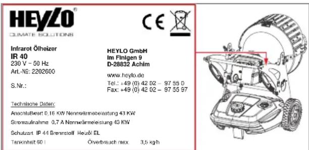
Fig. 18: Type plate on device
The type plate contains the following information:
- Model
- Type number
– Electrical connection data - Serial number
14.2 General description
The device is a compact and portable unit that produces radiation heat.
The device must only be operated:
– for the purpose for which it is intended
– in compliance with the safety instructions in chapter Safety [▶ 24]
Design and scope of delivery
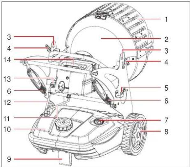
text_image
Technical diagram of a lawn mower with numbered parts for identificationFig. 19: Device design (operating side)
| 1 | Safety cover | 2 | Combustion chamber |
| 3 | Eyelets for attachment | 4 | Locking lever for heating plate angle |
| 5 | Power cord holder | 6 | Handles |
| 7 | Fuel tank level indicator | 8 | Transport wheel |
| 9 | Foot without wheel (optional) | 10 | Fuel tank |
| 11 | Fuel return line | 12 | Fuel supply line |
| 13 | Fuel filter | 14 | Control panel |
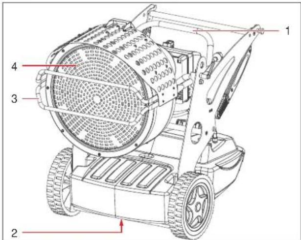
text_image
Technical diagram of a lawn mower with numbered parts labeled 1 to 4Fig. 20: Device design (front side)
| 1 | Angle adjusting device for heating plate | 2 | Fuel tank drain screw |
| 3 | Safety hoop | 4 | Heating plate |
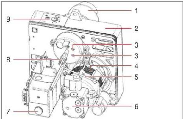
text_image
Labeled diagram of an electronic device with numbered parts for identificationFig. 21: Combustion chamber and nozzle holder
| 1 | Burner tube | 2 | Nozzle holder |
| 3 | Ignition electrodes (not shown) | 4 | Motor |
| 5 | Fuel line to nozzle | 6 | Oil pump |
| 7 | Reset button | 8 | Photocell (flame monitoring) |
| 9 | Adjusting screws of combustion chamber air damper |
The scope of delivery includes:
– Infrared oil heater with transport wheels
- Operating manual
Mode of operation
The device is a radiation heater with an oil burner.
The fuel is taken by the oil pump from the tank, compressed to operating pressure and fed to the nozzle. The nozzle injects the fuel as a mist into the combustion chamber where it ignites. The result is a flame which, together with its combustion gases, heats the combustion chamber and the heating plate.
The exhaust gases are fed out of the device.
The heating plate provides uniform radiation heat.
The heating output (two levels) of the device is controlled with the device switch.
The heating plate is protected by a guard and a safety hoop to prevent direct contact.
The exhaust gases are discharged through the heating plate.
Operation with room thermostat
The device can be run in conjunction with a room thermostat so that it is operated on the basis of the actual room temperature.
See also
Intended use [▶ 29]
14.2.1 Intended use
The device is designed to produce radiation heat. It is particularly suitable for the heating of small areas and of well-ventilated rooms and outdoor spaces (e.g. warehouses, workshops, construction sites). Intended use also includes compliance with the operating conditions (see Operating conditions [▶ 26]). Any use other than the specified is deemed improper. Improper use shall void all warranty cover.
See also
Technical data and factory settings [▶ 39]
14.2.2 Improper use
Any use other than the intended is prohibited. Improper use can lead to danger.
- Improper use includes interference with safety-relevant components of the device.
- Improper use includes further operation of the device under inadmissible operating conditions and insufficient maintenance.
14.2.3 Foreseeable misuses
Reasonably foreseeable misuse includes:
– Operation under inadmissible operating conditions, non-adherence to safety clearances
– Operation in small, or insufficiently ventilated rooms
– Unsupervised operation without installed room thermostat
14.3 Safety devices
If safety devices are not installed properly or configured incorrectly, there is a risk of injury. Do not modify, dismantle or disable safety devices. All safety devices must be freely accessible at all times. Familiarize yourself with the safety devices, in order to be able to prevent or minimise the risk of injury and/or damage to property.
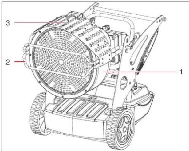
text_image
Technical diagram of a robotic lawn mower with numbered parts labeled 1, 2, and 3Fig. 22: Safety devices
| 1 | Housing | 2 | Safety hoop |
| 3 | Safety cover |
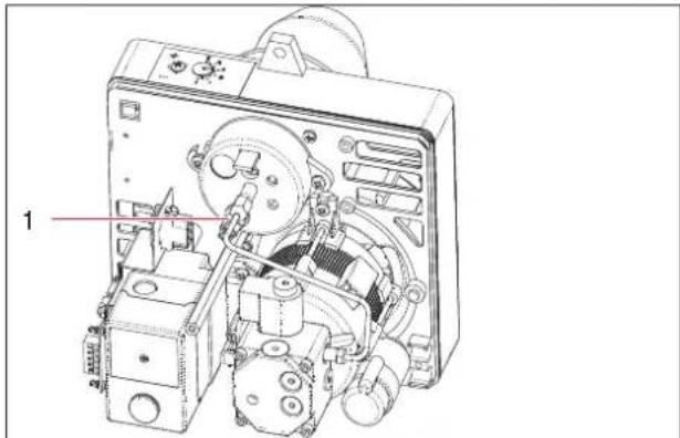
natural_image
Technical line drawing of an internal mechanical device with labeled component (no text or symbols present)Fig. 23: Safety devices of combustion chamber
| 1 | Photocell (flame monitoring) |
The device is equipped with the following safety devices:
- Photocell monitoring the flame in the combustion chamber to prevent operation of the device without a flame.
Signalling devices
The reset button at the control panel (see Control and display elements [▶ 30]) indicates the operating status of the device:
- If a burner malfunction occurs, the reset button is lit. To reset the burner, press and hold the reset button until the button is no longer lit.
Emergency shut-down
In the event of a burner malfunction, the device automatically switches off and the reset button is lit. Do not restart the device until all the malfunctions and defects have been rectified.
14.4 Control and display elements
The device is operated solely through the switches at the control panel. It can be controlled by a room thermostat (optional).
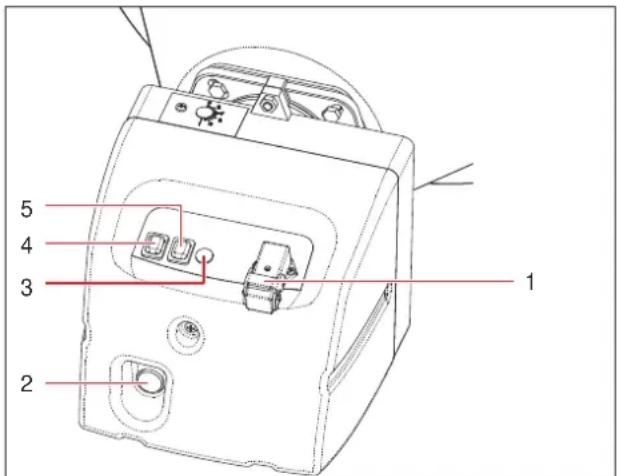
text_image
1 2 3 4 5Fig. 24: Control panel
| 1 | Room thermostat connection | 2 | Reset button |
| 3 | Operating status indicator | 4 | Device switch |
| 5 | Heating output switch |
The device switch turns the device on and off.
The reset button at the control panel is lit in the event of a malfunction or failure. After eliminating the malfunction, the device must be reset. To do this, press and hold the reset button until it is no longer lit.
The operating status indicator indicates that the device is switched on and running.
Room thermostat
By connecting a room thermostat (see Accessories [▶ 39]), the device can be operated without constant supervision. In this case, the device runs continuously until the set room temperature is reached.
15 Transport, installation and commissioning
The device has been assembled, configured and tested at the factory. Therefore, there may still be oil residues in the pipes.
In order to avert the risk of serious or fatal injury and damage to the device during transport and installation, observe the following:
- The device must be transported and installed by suitably qualified and authorised persons.
- Transport routes must be wide enough to transport the device safely.
- All work on the electrical equipment must be performed by qualified electricians.

DANGER
Danger to life from electric shock
Touching live parts can be fatal.
a) Before transporting the device to a different location, switch it off at the ON/OFF button and disconnect it from the power socket.
b) Never pull the device by the power cord; always move it by the handle provided.

CAUTION
Risk of injury from burns on hot surfaces
The housing of the device and in particular the heating plate with the guard and the safety, and the burner become very hot during operation. Particular caution is required at places where children or persons with a physical, sensory or mental disability are present.
a) Do not touch hot surfaces.
b) Wear protective gloves.
c) If children or persons with a physical, sensory or mental disability are present near the device, supervise them closely.

CAUTION
Risk of injury due to the device toppling over
There is a serious risk of injury, if the device topples over or falls during transport.
a) Wear safety footwear and protective gloves.
b) Use the transport wheels and the handles provided for this purpose.
c) Before transporting the device, make sure that the heating plate is firmly secured.
Unpacking
a) Open the packaging and remove it from the heater.
b) Check the delivery for completeness.
Report any transport damage or incomplete delivery to your dealer.
c) Dispose of the packaging according to the applicable statutory regulations.
d) Make sure that the power cord is not damaged.
Installing device
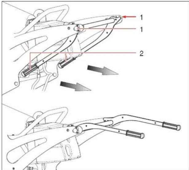
Fold out the handles on the device.
text_image
Technical diagram showing mechanical assembly steps with numbered components and directional arrows indicating motionFig. 25: Aligning handles
| 1 | Lock bolt | 2 | Handles |
a) Pull out the two lock bolts to disengage them from the bores in the handles.
b) Fold the handles out.
Refuelling
text_image
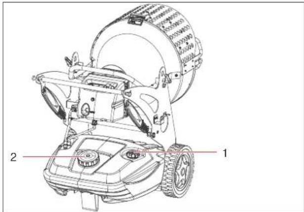
Technical diagram of a lawn mower with labeled parts and numbered reference linesFig. 26: Refuelling
| 1 | Fuel tank level indicator | 2 | Fuel tank cap |
a) Open the fuel tank cap and fill the tank with a suitable fuel (see also Fuel [▶ 25]). Do not overfill the tank. Monitor the filling level at the filling level indicator.
NOTICE! Use only fuels that are suitable for the device.
b) Close the fuel tank cap.
Installing device on site
To install the device on site, observe the Operating conditions [▶ 26] and the following rules:
- Transport the device using the handles.
- Position the device so that the air intake is not obstructed.
- Ensure adequate air circulation in front of and behind the combustion chamber. Keep the prescribed minimum distances to other objects (see Operating conditions [▶ 27]).
- Keep the device away from loose objects, including curtains, etc.
- Do not place the device on a wet surface.
- There should be no objects between the device and the item to be heated.
- The device must be in a stable position so that it cannot topple over or roll away during operation.
Connecting device to power supply
a) Connect the device to a power socket that is earthed or protected by an integrated RC circuit breaker (see Technical data and factory settings [▶ 39]).
⇒ The device is now installed and ready for operation.
Connecting external room thermostat
NOTICE
Use original accessories
To ensure reliable device operation, only connect original accessories to the device.
text_image
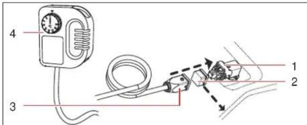
4 3 1 2Fig. 27: Connecting thermostat
| 1 | Socket for thermostat | 2 | Protective cap |
| 3 | Thermostat plug | 4 | Thermostat |
√ The device is in standby mode – the device is switched off and the power plug is connected.
a) Remove the protective cap from the device socket.
b) Plug the thermostat plug into the socket and lock the plug.
c) Place the thermostat in a suitable position.
16 Device operation and control
Safety instructions for operation

CAUTION
Risk of injury from burns on hot surfaces
The housing of the device and in particular the heating plate with the guard and the safety, and the burner become very hot during operation. Particular caution is required at places where children or persons with a physical, sensory or mental disability are present.
a) Do not touch hot surfaces.
b) Wear protective gloves.
c) If children or persons with a physical, sensory or mental disability are present near the device, supervise them closely.
Prior to switching on
a) Make sure that the device is not standing on a wet surface and that it is in an upright and stable position.
b) Make sure that there is fuel in the tank.
c) Make sure that the power cord is not damaged.
d) Make sure that the device is connected to a power socket with the correct voltage and protection (see Technical data and factory settings [▶ 39]).
e) Strictly adhere to all instructions in the Operating conditions [▶ 26] are adhered to.
Adjusting heating plate
a) Hold the angle adjusting device of the heating plate and loosen the two locking levers.
b) Move the heating plate to the desired position.
c) Tighten the two locking levers.
→ The heating plate is now at the desired angle.
Switching device on
natural_image
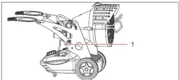
Technical line drawing of a robotic lawn mower with labeled parts (no text or symbols present)Fig. 28: Connecting device to power supply
| 1 | Power plug (not shown) |
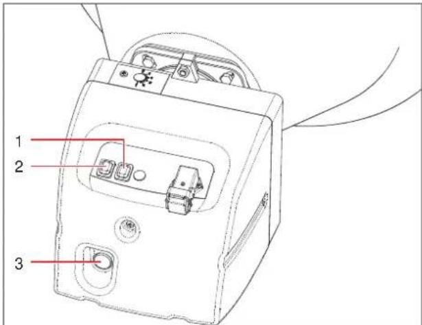
text_image
1 2 3Fig. 29: Switching device on
| 1 | Heating output switch | 2 | Device switch |
| 3 | Reset button |
a) Set the device switch at the control panel to position [ON].
⇒ The device starts within a few seconds. Should the device fail to start, refer to section Malfunctions during operation [▶ 34].
b) Select the heating output, using the heating output switch.
⇒ The device is switched on and runs in continuous mode.
Resetting device
If a malfunction occurs, the device is automatically switched to fault mode and the reset button is lit. In this case, the device must be reset.
√ The reset button is lit.
a) Eliminate the cause of the malfunction.
b) Press and hold the reset button for 2 seconds until it is no longer lit.
⇒ The device is reset and switches on automatically.
If you are unable to eliminate the cause of the problem, contact the HEYLO service department.
Switching device off

Attention
Damage to combustion chamber by disconnecting power plug
If the device is switched off by disconnecting the power plug, it cannot cool down properly, and this can lead to damage to the burner and the combustion chamber.
a) Always switch off the device with the device switch and let the cooling time elapse before disconnecting the device from the power mains.
a) Turn the device switch to position [OFF].
⇒ You have now switched off the device.
Operation with room thermostat
√ The room thermostat is connected and the device is ready for operation.
a) Set the room thermostat to the desired target temperature.
b) Turn the device switch to position [ON].
→ The device runs in heating mode as long as the room temperature is below the set target temperature.
⇒ The device is automatically switched off as soon as the set target temperature is reached. If the temperature drops again below the set target temperature, the device resumes heating operation.
17 Malfunctions
For troubleshooting, observe the following general rules:
- All work must be carried out by trained and authorised technicians.
- During the statutory warranty period, all work on the device must be carried out by the manufacturer or by persons authorised by the manufacturer.
a) Let the device cool down.
b) Wear suitable protective clothing.
c) Check all fuel pipes and fuel system components for leakage.
d) Before restarting the device, install all safety devices as attached at the factory.
e) Check that the safety devices are working properly.
f) After completion of the work, remove all tools and objects from the working area around the device.
Safety instructions for troubleshooting

DANGER
Danger to life from electric shock
Touching live parts can be fatal.
a) Before carrying out any work on electrical components, disconnect the power plug from the mains socket.

WARNING
Risk of deflagration
If the burner is repeatedly restarted without working properly, there is a risk of deflagration of the fuel that has collected in the combustion chamber.
a) Do not restart the burner more than 3 times in succession. Risk of deflagration!
b) Contact the HEYLO service department.

CAUTION
Risk of injury from burns on hot surfaces
The housing of the device and in particular the heating plate with the guard and the safety, and the burner become very hot during operation. Particular caution is required at places where children or persons with a physical, sensory or mental disability are present.
a) Do not touch hot surfaces.
b) Wear protective gloves.
c) If children or persons with a physical, sensory or mental disability are present near the device, supervise them closely.

CAUTION
Risk of injury due to missing guards
Missing guards can lead to injury.
a) Before switching on the device, install all guards that may have been removed for troubleshooting.
b) Check all the safety devices before switching on the device.

NOTICE
Cleaning combustion chamber and checking exhaust gas values
If there is soot in the combustion chamber, it might be necessary to clean it.
After cleaning the combustion chamber, check whether the heater runs without producing soot.
17.1 Restarting after an unscheduled downtime
Power failure
After a power failure, the heater might be in fault mode.
a) Press the reset button at the control panel and reset the burner.
b) Start the device.
If the device returns to failure mode, there might be a problem with overheating. In this case, shut down the device and arrange for the repair to be carried out.
17.2 Malfunctions during operation

NOTICE
If the device is supplied with power through the mains cord, work on the electrical system must only be carried out by a qualified electrician or an electrically instructed person in accordance with DGUV regulation 3 or DIN VDE 0105-100 or DIN VDE 0701-702.
Have all repair work on the electrical, gas and oil connections carried out by HEYLO service personnel or by HEYLO service partners.
To identify and eliminate problems, refer to the troubleshooting table below:
| Malfunction / message | Possible cause / remedy |
| Device fails to start or shuts down | Device switch in position [OFF]Set device switch to position [ON]. |
| No power supply- Connect the power plug to the socket.- Check the voltage of the power supply system. | |
| Power cord defectiveContact the HEYLO service department. | |
| Electronics blocked or defective |
| Malfunction / message | Possible cause / remedy |
| - Reset device (seeDevice operation and control [▶ 32]).- Contact the HEYLO service department. | |
| Incorrect room thermostat settings (optional equipment)Set the room thermostat to a temperature that is higher than the current ambient temperature. | |
| No fuelTop up fuel and reset the device. | |
| Fuel line blocked- Empty the tank and fill it with clean fuel (seeChecking and cleaning the device [▶ 36]).- Clean the filter (seeChecking and cleaning the device [▶ 36]).- Contact the HEYLO service department. | |
| Insufficient oil pressureContact the HEYLO service department. | |
| Nozzle blockedContact the HEYLO service department. | |
| Incorrect ignition electrode settingsContact the HEYLO service department. | |
| Device emits smoke | Fuel line blocked- Nozzle dirty (for cleaning instructions, seeChecking and cleaning the device [▶ 36]).- Dirt/paraffin in fuel (seeChecking and cleaning the device [▶ 36]).- Incorrect pump pressure (seeChecking and cleaning the device [▶ 36]).- Clean the filter (seeChecking and cleaning the device [▶ 36]).- Contact the HEYLO service department. |
| Incorrect burner settingsCheck the burner settings and adjust them, if necessary (seeAdjusting combustion chamber damper [▶ 37]). | |
| Device can-not be switched off | Electronic defectContact the HEYLO service depart-ment. |
Tab. 6: Troubleshooting table
See also
Burner service [▶ 37]
18 Cleaning and maintenance
For cleaning and maintenance, observe the following general safety rules:
- All work must be carried out by trained and authorised technicians.
a) Switch off the device before starting work, wait until the cooling phase has elapsed and then disconnect the mains plug.
b) Wear suitable personal protective equipment.
c) Before restarting the device, install all safety devices as attached at the factory.
d) Check that the safety devices are working properly.
e) After completion of the work, remove all tools and objects from the working area around the device.
f) Use only original spare parts and accessories.

DANGER
Danger to life due to electric shock
Touching electrically live parts can be fatal.
a) Switch off the device and pull out the mains plug.

CAUTION
Risk of injury from burns on hot surfaces
The housing of the device and in particular the heating plate with the guard and the safety, and the burner become very hot during operation. Particular caution is required at places where children or persons with a physical, sensory or mental disability are present.
a) Do not touch hot surfaces.
b) Wear protective gloves.
c) If children or persons with a physical, sensory or mental disability are present near the device, supervise them closely.

CAUTION
Risk of injury from inadvertent device start-up
Uncontrolled start-up of the burner can lead to injury.
a) Switch off the device at the device switch and disconnect the power plug.

CAUTION
Risk of injury due to missing guards
Missing guards can lead to injury.
a) Before switching on the device, install all guards that may have been removed for troubleshooting.
b) Check all the safety devices before switching on the device.

CAUTION
Risk of injury from not wearing personal protective equipment
When cleaning and maintaining the device, you may injure yourself on sharp edges, or through inhaling or coming into contact with toxic substances.
a) Wear protective gloves and respiratory protection.

Attention
Damage to device from insufficient maintenance
Insufficient maintenance leads to excessive wear and expensive repairs.
a) Carry out the necessary maintenance work in accordance with the manufacturer's instructions.
b) In the event of damage to mechanical parts, switch off the device without delay and arrange for professional repair with original spare parts.

NOTICE
Performing regular maintenance
Regular maintenance is part of proper use and indispensable for safe and efficient operation.
18.1 Checking and cleaning the device
The cleaning intervals for the device depend on the actual operating conditions. Check and clean the device regularly.

NOTICE
Suitable cleaning products
Suitable cleaning products for your device are available from your dealer or directly from HEYLO.
- Cleaning can be performed with compressed air, a vacuum cleaner or by wiping with a damp cloth. CAUTION! Never use a hose or high pressure cleaner.
- The electrical system must be checked regularly for signs of damage.
- To ensure trouble-free operation, regularly check and clean the filters of the device.
Switching device off
To clean and check the device, switch it off as follows:
a) Switch off the device at the device switch and let the cooling time elapse.
b) Disconnect the power plug.
Cleaning device housing
a) Clean the housing with a damp, lint-free cloth and a mild detergent. The original gloss can be restored with polish.
Cleaning fuel tank
Clean the fuel tank at least once a year, or as required.
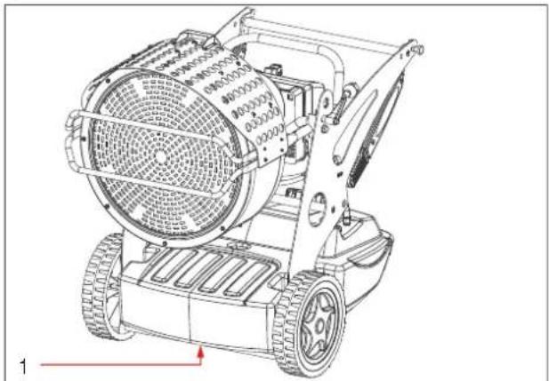
natural_image
Technical line drawing of a robotic lawn mower with visible mesh and wheel components (no text or symbols)Fig. 30: Emptying fuel tank
| 1 | Fuel tank drain screw |
a) Place a container that can hold the entire tank volume under the fuel tank drain screw.
b) Remove the drain screw.
c) Rinse the tank with clean fuel.
d) Dispose of fuel according to the relevant statutory regulations.
Cleaning filter
Clean the filter at least once a year, or as required. Always replaced damaged filters.
Cleaning tank inlet filter
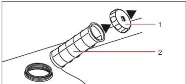
text_image
Diagram of a mechanical component with labeled parts 1 and 2, showing internal structure and assembly.Fig. 31: Cleaning inlet filter
| 1 | Screw cap of fuel tank | 2 | Inlet filter |
a) Open the fuel tank cap.
b) Pull the inlet filter from the tank.
c) Clean the inlet filter with clean fuel. Do not damage the filter.
d) Mount the inlet filter in the tank.
e) Mount the screw cap.
Cleaning oil filter
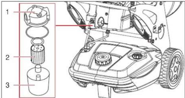
text_image
Technical diagram of a robotic car with labeled parts including engine, gear, and motor assemblyFig. 32: Cleaning oil filter
| 1 | Filter lid | 2 | Filter cartridge |
| 3 | Filter cup |
The oil filter must be checked regularly and replaced if necessary. Proceed as follows:
√ Keep a cloth to collect any escaping fuel ready.
a) Turn the filter cup counter-clockwise and pull it down.
Collect the escaping fuel, remove the gaskets and keep them safely.
b) Turn the filter cartridge counter-clockwise and pull it from the filter cup.
Collect the escaping fuel.
c) Clean the filter cup and filter cartridge with clean fuel. Do not damage the filter.
If the filter cartridge is damaged, replace it.
d) Install the filter cartridge in the filter cup.
e) Mount the filter cup on the filter lid. Ensure that all gaskets are correctly installed.
f) Dispose of the replaced filter cartridge and the fuel according to the relevant statutory regulations.
Cleaning fuel pump filter
The fuel pump filter must be cleaned at least once a year, or as required. Contact the HEYLO service department.
Replacing oil nozzle
The oil nozzle must be replaced at least once a year. Contact the HEYLO service department.
Cleaning ignition electrodes, fan propeller and combustion chamber
The ignition electrodes, fan propeller and combustion chamber must be cleaned as required. Contact the HEYLO service department.
18.2 Inspecting electrical system

DANGER
Touching electrically live parts can be fatal.
Improper or inadequate inspection and maintenance can lead to device components becoming live during device operation.
a) The electrical system must be inspected and serviced by a qualified electrician.
b) Once the work has been completed, all safety devices must be reinstalled as specified and checked.
a) Check all the electrical components of the device for visible damage, loose contacts and contamination. To do this, remove the guard in order to inspect the internal wiring. Remove any external contamination with a lint-free cloth and replace any defective or damaged components.
b) If used commercially in Germany: An annual DGUV V3 inspection in accordance with German Statutory Accident Insurance (DGUV) rules must be carried out and documented.
⇒ The inspection of the electrical system of the device is now complete.
18.3 Burner service
The burner must be serviced regularly as follows:
- Clean the oil filter (see Checking and cleaning the device [▶ 36])
- Adjust the combustion chamber damper (see Adjusting combustion chamber damper [▶ 37])
All burner maintenance work must be carried out at the start of a shift:
a) Allow the device to cool and then unplug the power cord.
For any of the tasks below, contact the HEYLO Service department (see also Malfunctions during operation [▶ 34]):
- Replacing oil nozzle
- Adjusting ignition electrode settings
- Adjusting pump pressure
- Exhaust gas analysis
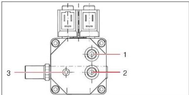
Oil pump service
To service the oil pump, you need additional information about pump settings. Contact the HEYLO service department.
text_image
1 2 3Fig. 33: Oil pump
| 1 | Connection for pressure gauge | 2 | Connection for vacuum gauge |
| 3 | Oil pressure adjusting knob (sealed, only for HEYLO service personnel) |
18.3.1 Adjusting combustion chamber damper
The combustion chamber damper must be checked regularly and readjusted, if necessary. The opening of the damper depends primarily on the ambient temperature.
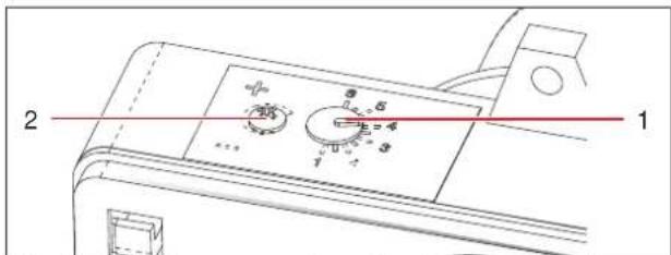
text_image
2 1Fig. 34: Adjusting screws of combustion chamber air damper
| 1 | Damper adjusting screw | 2 | Damper fine-tuning screw |
√ Shut down the device, let it cool down and disconnect it from the power mains.
a) Loosen the screws of the control panel housing cover.
b) Remove the housing cover.
c) Using a screwdriver, turn the damper adjusting screw to the value specified in the separate burner head manual.
The fine-tuning screw is used to ensure soot-free operation.
d) Mount the housing cover.
⇒ The combustion chamber damper is correctly set.
18.4 Wear and spare parts
Spare parts must meet the technical requirements specified by HEYLO. HEYLO original spare parts must meet stringent requirements.
HEYLO assumes no warranty for damage caused by the use of spare parts from other manufacturers.
To order wear and spare parts, please contact your dealer or HEYLO directly, providing the following information:
- Device type
- Serial number,
– Designation of the component - Quantity
- Shipping method
See also
Contact to HEYLO GmbH [▶ 24]
18.5 Customer service by the manufacturer
HEYLO recommends taking out a maintenance contract with the HEYLO Service Department.
See also
Contact to HEYLO GmbH [▶ 24]
19 Repairs
This section describes which repair tasks can be performed by whom.

NOTICE
During the warranty period, all repairs must be performed by persons authorised by the manufacturer.
Repair by device owner
After the warranty period has elapsed, certain repair can be carried out by the device owner, provided he or she has the necessary skills. HEYLO shall not be liable for damage caused by such repairs.
If you have any questions about repairs, contact the HEYLO service department or your dealer.
See also
Contact to HEYLO GmbH [▶ 24]
20 Decommissioning, storage and disposal
The following principles apply for the decommissioning, storage and disposal of the device:
These tasks may only be carried out by trained and authorized specialists.

DANGER
Danger to life due to electric shock
Touching electrically live parts can be fatal.
a) Switch off the device and pull out the mains plug.
20.1 Decommissioning
Temporary decommissioning
a) Switch off the device at the device switch and let the cooling time elapse.
b) Disconnect the power plug.
c) Empty the fuel tank and dispose of the fuel according to the statutory regulations.
d) Clean the device (see Checking and cleaning the device [▶ 36]).
⇒ The device has now been temporarily decommissioned.
Final decommissioning
√ Carry out all the steps needed for temporary decommissioning.
a) Disconnect all the incoming and outgoing lines (power supply lines).
⇒ You have now taken the device permanently out of service.
See also
Contact to HEYLO GmbH [▶ 24]
20.2 Storing the device
a) Before putting the device in storage, run it briefly in heating mode with winter diesel to fill the pipes with a frost-proof fuel.
b) Store the device in a dry place where it is protected against frost. Observe the prescribed storage temperature range (see Technical data and factory settings [▶ 39]).
20.3 Disposal
The device is primarily made of recyclable materials. If handled properly, it does not present a hazard to the operator and the environment. However, operation of the device might produce waste containing harmful and/or environmentally hazardous substances (air filters). These materials must be disposed of properly according to the statutory regulations.
The individual components of the device (e.g. pumps, metal components, etc.) must be taken to a qualified disposal and recycling company. Commission a qualified, specialist company to dispose of and recycle the device.
See also
Contact to HEYLO GmbH [▶ 24]
21 Technical data and factory settings
| Model | IR 40 |
| Prod. no. | 2202600 |
| Rated heat output [kW / BTU/h / kcal/h] | 43 / 146900 / 37000 |
| Fuel autonomy [h] | 14 |
| Fuel consumption [l/h] | 4.03 |
| Admissible fuelsAt temperature below 5°C | Diesel, petrolWinter diesel |
| Fuel tank capacity [l] | 60 |
| Power connection [V/Hz] | 220-240 / 50 |
| Power consumption [kW] | 0.16 |
| Current consumption [A] | 0.7 |
| Protection class [IP] | 44 |
| Weight without fuel [kg]Length [mm] | 691070 |
| Width [mm] | 700 |
| Height [mm] | 980 |
Tab. 7: Technical data
| Parameter | Value |
| Oil pump pressure [bar] | 10 |
| Oil nozzle injection rate [US gal/h] | 0.85 |
| Air intake setting | 4-4.5 |
| Burner head setting | 4 |
| Nozzle type | 0.85 gal/h |
| Parameter | Value |
| 60°S Danfoss |
Tab. 8: Factory settings
22 Supplementary documents
22.1 Accessories
| HEYLO art.no. | Description |
| 1240100 | Room thermostat |
22.2 Declaration of conformity
EC Declaration of Conformity IIA in accordance with EC Machinery Directive 2006/42/EC

For device series: Oil heater
Type: IR 40
HEYLO GmbH, of Im Finigen 9, 28832 Achim, Germany, hereby declares that the design and construction of the equipment described in this document in the version provided by us comply with the fundamental health and safety requirements specified in Directive 2006/42/EC, Annex I.
Applicable European Directives:
Machinery Directive 2006/42/EC
Low Voltage Directive 2014/35/EC
EMC Directive 2014/30/EC
Unauthorised modifications to the equipment shall void this Declaration of Conformity.
Applied standards:
EN 62233:2008
- Managing Director -
SIE HABEN FRAGEN? WIR HELFEN IHNEN GERN! Do you have any questions? We are happy to help you!
HEYLO Kundendienst – Technischer Support und Service HEYLO Customer Service – Technical Support and Service
Tel. +49 (0) 42 02 - 97 55 15