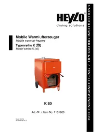
K 80 - Heating Heylo - Free user manual and instructions
Find the device manual for free K 80 Heylo in PDF.


| Product Type | Direct Fired Diesel Heater |
| Brand | Heylo |
| Model | K 80 |
| Heating Output | 80 kW (273,000 BTU/h) |
| Fuel Type | Diesel or Kerosene |
| Fuel Consumption | 6.5 L/h (full load) |
| Airflow | 3200 m³/h |
| Power Supply | 230 V / 50 Hz |
| Power Consumption | 500 W (fan and pump) |
| Dimensions (L x W x H) | 1200 x 600 x 800 mm |
| Weight | 45 kg |
| Fuel Tank Capacity | 50 L |
| Noise Level | 72 dB(A) |
| Ignition Type | Automatic electronic ignition |
| Safety Features | Overheat protection, flame failure device, thermostat control |
| Construction | Steel housing with powder coating |
| Maintenance | Clean fuel filter and nozzle periodically; check spark plug |
| Warranty | 2 years |
Frequently Asked Questions - K 80 Heylo
User questions about K 80 Heylo
0 question about this device. Answer the ones you know or ask your own.
Ask a new question about this device
Download the instructions for your Heating in PDF format for free! Find your manual K 80 - Heylo and take your electronic device back in hand. On this page are published all the documents necessary for the use of your device. K 80 by Heylo.
USER MANUAL K 80 Heylo
Mobile warm-air heaters
Typenreihe K (Öl)
Model series K (oil)

K 80
EU Declaration of Conformity
In accordance with the EU Machinery Directive (98 / 37 / EC) Annex II A
For equipment
construction series: Fan-assisted air heaters with heat exchangers
Type: K 30, K 30 T, K 50, K 80, K 120, K 160 eco, K 170, K 220
HEYLO GmbH, Im Finigen 9, 28832 Achim, declares that the machines described correspond to the EU Machinery Directive as far as safety and health requirements are concerned, in their design and in the construction type brought into use by us.
The declaration will lose its validity if unauthorised changes are made to the machines.
Applicable EC Directives: Machinery Directive 98 /37 /EC
Low Voltage Directive 2006 / 95 / EC
EMC Directive 2004 / 108 / EC
Harmonised standards used:
- DIN EN 12100-1 01:2003 Safety of machinery – Basic concepts,
general principles for design
Part 1: Basic terminology and methodology - DIN EN 12100-2 02:2003 Safety of machinery – Basic concepts,
general principles for design
Part 2: Technical principles and specifications - DIN EN 60204-1 06 : 2007 Safety of machines and electrical equipment
of machines - DIN EN 50081-2 03 : 1993 Electromagnetic compatibility – generic emission
standard, industrial environment
National standards as well as technical specifications used:
- DIN 4794-1 12:1980 Stationary fan-assisted air heaters with and
without interchange of heat
- DIN 4794-2 12:1980 Stationary fan-assisted air heaters
with interchange of heat
Achim, 18-10-2011
Milledo
Dr. Thomas Wittleder
- Manager -
Contents
Page
- General information 23
- Technical Data 24
- Equipment Construction 25
- Mode of operation 26
- Connections 26
- Commissioning/starting up 27
- Installation Guidelines 28 – 29
- Maintenance 29
- Troubleshooting 30 - 32
- Wiring 33
- Parts list 34 – 36
- Burner adjustment 37
- Spare parts for oil burner 38 - 39
PLEASE NOTE:
Please read without fail before starting up!
Please observe the advice given in the operating instructions carefully. If you do not observe it, the claim for a guarantee will expire. The manufacturer is not liable for damages or subsequent damages that may arise.
1. General information
Equipment description
The K 80 lit with heating oil EL, is a compact fan-assisted air heater (WLE) that can be used in many ways and is easy to transport for heating and drying. It functions equally well with and without a chimney and, with its high heat capacity, it is compact and light, but still built as a robust device. The WLE can only be used commercially.
Fan-assisted air heaters are intended for spot heating of repair areas in the open and in closed rooms, for thawing and heating of machines, devices and pipelines and for drying of rooms, hay and crops as well as auxiliary heating in emergency cases.
A tested oil burner has been installed in accordance with DIN EN 267. The current operating instructions for the WLE will definitely be supplemented by the operating instructions of the burner manufacturer for the burner.
Safety instructions
The equipment can only be operated by sufficiently trained persons.
Mobile fuel containers can only be installed and operated under observation of the Technical Regulations for Combustible Fluids (TRbF 20).
Do not install and operate the equipment in oily, sulphurous or salty environments.
The equipment should not be exposed to sprayed water (e.g. high pressure cleaners).
Only WLE models of blower oil burners in accordance with DIN EN 230 and DIN EN 267 can be used.
On no account can the safety facilities be blocked or bridged over.
The equipment can only be operated unsupervised with a thermostatic regulator.
Strictly speaking, the equipment should only be disconnected from the mains supply in a cooled off state.
Equipment must be installed on level surfaces, ensuring that they are stable.

All devices have a CE mark
- Technical Data for the Model Series K
| Type K 30 K 30 T K 50 K 80 | K 120 | K160 eco1st //2ndlevel | K 170 | K 2201st / 2ndlevel | ||||
| Item No. | 1101605 | 1101610 | 1101584 | 1101600 | 1101625 | 1101670 | 1101683 | 1101684 |
| Nominal heat load (kW) | 32 | 32 | 54 | 83 | 120 | 141 / 161 | 168 | 155 / 234 |
| Nominal heat output (kW) | 29 | 29 | 50 | 76 | 110 | 133 / 151 | 153 | 148 / 219 |
| Nominal volumetric air flow at 20°C | 1800 | 1800 | 3600 | 5700 | 7900 | 10500 | 10130 | 11400 / 14100 |
| Hot air flow at Δt (m3/h) | 2050 | 2050 | 4200 | 6500 | 8900 | 12600 | 11000 | 11650 / 16100 |
| Temperature increase Δt (K) | 46 | 46 | 45 | 45 | 42 | 45 | 48 | 43 / 42 |
| Max .available internal static pressure (Pa) | 50 | 50 | 100 | 100 | 150 | 150 | 250 | 360 / 625 |
| Sound volume at 5 m distance dB(A) | 58 58 | 59 59 72 | 77 52 | 59/68,1 | ||||
| Connection for power supply (V/Hz) | 230/50 | 230/50 | 230/50 | 230/50 | 230/50 | 230/50 | 400/50 | 400/50 |
| Power input (A) | 2,2 | 2,2 | 2,8 | 2,45 | 4,9 | 7,7 | 6,5 | 7,2 / 10,2 |
| Power consumption (kW) | 0,50 | 0,50 | 0,65 | 0,56 | 1,13 | 1,77 | 2,65 | 2,50 / 3,58 |
| Protection class (IP) | 44 44 | 44 44 44 | 44 44 | 44 | ||||
| Fuel consumption (kg/h)Heating oil EL | 2,5 | 2,5 | 4,7 | 6,8 | 10,1 | 11,9/13,1 | 14,0 | 13,1 / 19,0 |
| Exhaust gas loss % | 9,1 | 9,1 | 9,0 | 8,0 | 7,0 | 5 | 8,7 | 4,9 / 6,4 |
| Required chimney draught (Pa) | 0 | 0 | 0 | 0 | 0 | 0 | 0 | 0 |
| Mass flow of exhaust gas max. (kg/s) | 0,015 | 0,015 | 0,025 | 0,038 | 0,054 | 0,09 | 0,099 | 0,072 / 0,069 |
| Equipment dimensions: | ||||||||
| Length (mm) | 1447 | 1447 | 1623 | 1674 | 1878 | 2000 | 2191 | 2298 |
| Width (mm) | 690 | 690 | 795 | 875 | 971 | 1002 | 1002 | 1294 |
| Height (mm) | 822 | 822 | 1082 | 1300 | 1410 | 1510 | 1510 | 1709 |
| Weight with burner (kg) | 73 | 85 | 140 | 190 | 225 | 330 | 340 | 480 |
| Exhaust gas pipe - diameter (mm) | 150 | 150 | 150 | 150 | 200 | 200 | 200 | 200 |
| Blow-out nozzle - diameter (mm) | 2 x 205 | 2 x 205 | 420 | 520 | 550 | 550 | 550 | 2 x 550 |
| Thermostat settings: | ||||||||
| Ventilator thermostat TR (°C) | 35 | 35 | 35 | 35 | 35 | 35 | 35 | 35 |
| Temperature monitor TW (°C) | 80 | 80 | 80 | 80 | 80 | 80/70 | 80 | 80 |
| Safety temperature limiter STB (°C) | 100(fixed) | 100(fixed) | 100(fixed) | 100(fixed) | 100(fixed) | 100(fixed) | 100(fixed) | 100(fixed) |
3. Equipment construction
A ventilator and chromium-titanium combustion chamber with a heat exchanger and exhaust gas nozzle fitted in the housing. The oil burner is installed in the switch cabinet with its control units within the casing and above the air suction unit. The tuyere connection with the flame pipe is fitted on the vertically placed combustion chamber. Both functional units are connected to each other by means of supply lines for air, fuel as well as ignition and monitoring bodies. Since the flame reverses within the combustion chamber, it has to be long and slender.
Capillary tube thermostats are installed in the device. The temperature regulator ensures that heating times are short when heating up by delayed switching on of the ventilator. When switching off, the temperature regulator allows the ventilator to run for some more time to remove the remaining heat from the device. The combustion chamber is thus protected from overheating due to subsequent heat at the same time.
Efficient oil pre-heating has been installed in the devices for operation during cold external temperatures. It heats up a specific amount of heating oil until the burner can start up.
The room thermostat connection permits room temperature dependent control of the device using a room thermostat.
An operating hour counter has been fitted into the device. It indicates running times of the device in [h] during heating operation. The running times can be read after opening the door of the switch cabinet.
4. Mode of operation
During operation, the heating oil EL is sucked in by the combustion pump through the suction pipe from the supplied tank or from a firmly installed oil supply unit. The amount of oil required for the heating performance is introduced into the burner nozzle through the pressure pipe, sprayed into the combustion chamber and ignited. A flame lights up, which, together with its combustion gases, heats the combustion chamber and the heat exchanger. Excess heating oil conveyed from the pump flows back into the container.
After a short heating up time, the temperature regulator switches on the ventilator. A very short heating up time is achieved in this way. The ventilator blows the sucked in air through the combustion chamber and the heat exchanger. It is heated up in this way. The heated up air exits on the opposite side through the blow-out nozzle.
The main switch is switched on to position -II- "heating" for heating up. First, the burner starts up and after heating up the combustion chamber and heat exchanger, the ventilator is also switched on and conveys hot air.
A room thermostat that is possibly attached later on has to be set higher than the ambient temperature, otherwise the device will not start up, since there will be no electricity supply.
The main switch is switched on to position -I- "ventilate" on the switch cabinet for ventilation. Only the ventilator is running now. The device is now functioning as a ventilation device.
The main switch is set to position -0- to switch off the device.
Main switch
VENTILATE
OFF
HEAT

5. Connections
Power supply connection
The device is operated with 230V alternating current, 50 Hz. The K 80 is operated through a 2.5 m long cable with a three-pin plug. Power supply connection should only take place on networks that are secured with a fuse of a minimum of 10 A. Longer supply lines should have a cross section of at least 3 × 2.5 mm2 or. 5 × 2.5 mm2 to avoid a drop in voltage in the device that is too high. In the case of low voltage of up to 195 V the device still functions flawlessly, so check the device's voltage if there are disruptions.
Operation with room thermostat
If the device is to keep the temperature in closed rooms constant, a 230 V room thermostat is connected to it. The cap on the connector must be removed for this purpose. The thermostat plug can now be plugged into the connector socket.
Oil pre-heating
Heating oil secretes paraffin at low temperatures. It blocks the oil filter and stops it from pumping. The devices do not start up and are therefore equipped with electrical heating elements. Oil pre-heating enables the oil to flow. It is controlled by a thermostat, independent of the device switch. However, the mains supply plug must be connected to a functioning and secured power supply source.
Chimney connection
Although the devices do burn without a smoke tube in the open and in open rooms, we recommend 1 m of tubing with a 150 mm diameter and a rain hood to stop penetration of rain and dirt as far as possible and to produce less of a draught.
In case of temporary operation in closed rooms, e.g. winter construction projects, the combustion gases must be discharged into the open. The exhaust gas pipe must be laid out in such a way, that at least 10 Pa draught is ensured in it and no counter pressure whatsoever is possible in the pipe. For this reason, please take care that the exhaust gas pipe is inclining and that it runs vertically upwards towards the end. It should at least be led above eaves height, even better above ridge height, to prevent counter pressure from the wind and thus emission of swirling soot from the burner. The exhaust gas pipes must be located at a minimum distance of 0.5 m from the combustible parts and be firmly attached. Their diameter should not be smaller than that of the exhaust gas nozzle of the fan-assisted air heater.
According to construction regulations, connection to a chimney with a 200 mm diameter that has to be led at least 0.40 m above the ridge, is prescribed for permanent operation in closed rooms.
6. Commissioning/start up
Heating
- Connect the device to the oil supply lines through the flow connection and return port.
- Plug in the mains plug in the appropriate mains supply socket.
- If prescribed by the construction regulations, connect the chimney, else 1 m smoke tube with rain hood.
-
Turn on the main switch to position -II- "heating." The burner will start up in the pre-ventilation mode. After approx. 45 sec. the flame will ignite.
-
If the device and/or oil are cooled off, you will have to wait for 15 - 20 minutes depending on the temperature until the oil pre-heating has pre-heated sufficiently. Only turn the main switch on to the heating mode after this and, if it is being used, set the connected room thermostat above ambient temperature.
-
Switching off: Turn off the main switch on the switch cabinet - do not pull out the mains plug - since the ventilator must keep running for a short while after switching off to cool. The temperature regulator will switch the ventilator off automatically with a delay of 2 -3 minutes. This process can repeat itself a few times. Do not, therefore, pull out the mains plug to switch the device off for any reason. If the device is turned off by pulling its plug or by pulling at the main switch, the device cannot cool off afterwards and this can lead to damages to the combustion chamber and to flame monitoring.
In certain circumstances, the safety temperature limiter can switch itself off and lock automatically. The device will then only start up again after unlocking the safety temperature switch.
Ventilation
- Turn the main switch on to position -I- "ventilate."
- To switch off ventilation: Set main switch to position -0- "Off."

7. Installation guidelines
Regulations for installation
When installing mobile WLEs with closed combustion chambers, the respective local construction and fire protection regulations as well as regulations prescribed by professional associations must be adhered to, in principle.
Installation locations
The devices cannot be operated in places where ignitable air-gas or dust-air mixtures could occur (e.g. petrol pumps, painting workshops, etc.)
Floors and ceilings must be fireproof. Suctioning-in and blow-out nozzles should not be narrowed.
Installation rooms/spaces
-
Installation of the WLE in closed, well ventilated rooms with a chimney connection:
-
The minimum size of a room must correspond to an average heat requirement in the room where the device is installed of 0.058 kW/m 3 .
- Fresh air supply required for flawless combustion must be guaranteed in any case (windows, doors or other openings).
| Heating capacity (kW) | Room size (m3) | Required amount of fresh air (m3/h) |
| 25 kW | 500 m3 | 50 m3/h |
| 50 kW | 1000 m3 | 80 m3/h |
| 80 kW | 1400 m3 | 130 m3/h |
| 110 kW | 1900 m3 | 180 m3/h |
| 140 kW | 2500 m3 | 220 m3/h |
| 160 kW | 2800 m3 | 240 m3/h |
-
Installation of the WLE in closed, well ventilated rooms without chimney connection:
-
The minimum size of the room must correspond to an average heat requirement of the room where the device is going to be installed of 0.058 KW/m 3 .
- On principle, a natural regeneration of air to 2.5 times that of the room content/h must be ensured (removal of the combustion gases and introduction of fresh air).
- The following openings are required for this amount of fresh air and outgoing air: Fresh air: 2.8 m 3
Outgoing air: 2.8 m 3
| Heating capacity (kW) | Amount of fresh air (m3/h) | Natural air regeneration (m3/h ) |
| 25 kW | 500 m3 | 1250 m3/h |
| 50 kW | 1000 m3 | 2500 m3/h |
| 80 kW | 1400 m3 | 3500 m3/h |
| 110 kW | 1900 m3 | 4750 m3/h |
| 140 kW | 2500 m3 | 6250 m3/h |
| 160 kW | 2800 m3 | 7000 m3/h |
Safety clearance
- On the sides of combustible parts: 0.60 m
- Blow-out side of combustible parts: 2.00 m
- Suctioning-in side for free in-flow of air: 0.60 m
- upwards: 3.00 m
Legal regulations
The following regulations must be observed during installation and start-up:
- Arbeitsstättenverordnung (Health and Safety at Work Act) §§ 5 and 14
- Arbeitsstättenrichtlinie ASR 5 (Health and Safety at Work directive)
- Unfallverhütungsvorschriften VBG 43, VBG 21(Accident Prevention Regulations)
- Feuerungsanlagenverordnung (FeuVo) (Ordinance for Combustion Equipment) of the individual German states.
The device has to be maintained and cleaned at regular intervals to ensure operational safety and maintenance of prescribed ecological limits as well as economic viability.
Maintenance work can only be carried out by competent experts. A fan-assisted air heater that is always kept clean ensures good combustion with undisturbed operation and a long life.
PLEASE NOTE !!! Pull out the mains plug first before doing any maintenance work!
- The oil filter must be cleaned after every heating period or sooner.
- The internal parts must be cleaned thoroughly to remove dust and dirt after every heating period or sooner, depending on how much dirt there is at the place of use.
- Soot must be removed from the combustion chamber after every heating period and the burners must be checked for flawless values (can only be carried out by a specialist).
- Only use original spare parts.
There are 3 openings on the K 80 to clean the heat exchanger. One is on the exhaust gas nozzle and can be opened by removing the hood and loosening the screws on the flange. The second and third openings for cleaning are on the blow-out and suctioning-in sides of the heat exchanger. Please remove the maintenance covering for this purpose.
- Troubleshooting
| Problem | Possible cause | Solution |
| Burner is not running | No power supply | Check with a voltage tester or lamp, turn on the main switch, change the fuse, check the supply line for loose contacts. |
| If device is being operated without room thermostat: check whether the cap of the room thermostat connection is on, since the heater will not start up without the cap, if necessary, place the cap on (the cap contains a power supply bridge). | ||
| Room thermostat (if being used) has been set too low | Set room thermostat above room temperature | |
| Room thermostat is defective | Examine room thermostat (can only be carried out by an expert). Change it or bridge it over at the fastening clamp on the device in emergency cases and switch it on manually. | |
| Automatic oil lighting device indicates disturbance (Lamp indicating disturbances lights up). | Unscrew the switch cabinet covering. After waiting for approx. 1 minute, activate the lit up button for removing disturbances on the control unit of the burner. The indication of a disturbance on the control unit and signal should go off. The burner then attempts to start up again. | |
 | When starting up initially, it is possible that the button for removing disturbances has to be pressed so often, until the burner has sucked in oil that is free of air. Check that the oil in the reverse flow pipe is free of bubbles. Heating up will only be possible after this. | |
| The safety temperature limiter has interrupted the power supply, blow-out temperature is too high, air input and air output have been narrowed down or device could not cool off afterwards: device was switched off by pulling out the plug, instead of by switching off. | Turn the black protective cap to the left and remove it. Press the button for removing disturbances on the STB. This can be found above the entry point for the device cable. Get rid of the cause for overheating (resistance to suctioning-in or blowing out). | |
| Problem | Possible cause | Solution |
| Burner starts up, but then indicates malfunctioning | Oil tank is empty | Fill up with oil |
| Oil pipe is not connected or main tap is closed | Check pipeline and/or main tap | |
| Oil filter is dirty | Clean nozzle filter, pump filter, prefilter, if necessary, change nozzle | |
| Oil suctioning pipe is not hermetically sealed, pump sucks in air with it | Seal off oil suctioning pipe. The oil in the reverse flow pipe should be free of bubbles. | |
| Oil pump is not producing any pressure | Set the pressure correctly. Change the coupling or pump (can only be carried out by an expert).Activate button for removing disturbances on the control unit (see section describing burner not starting up) | |
| Burner starts up but does not ignite, indicates malfunctioning | No ignition spark. Carbon deposits on ignition electrodes or they are displaced.Burner nozzle is blocked | Check the tuyere connection. Pull out the mains plug or switch off the power supply and check the tuyere connection.Unscrew the burner nozzle.Change the nozzle for a new one.Do not attempt to clean the nozzle!Keep changing the nozzle, opened, cleaned nozzles never burn flawlessly. |
| Flame goes out after starting up or burns intermittently | The photo conductive cell is dirty | Pull out the photo conductive cell and wipe it with a clean cloth. This cleaning should take place often in very dusty rooms. |
| Oil filter is dirty | Check and clean all oil filters: prefilters, pump filters, nozzle filters. | |
| Oil suctioning pipe is not hermetically sealed, pump sucks in air with it: air bubbles in the oil in the reverse flow pipe.Burner nozzle blocked | Seal off the oil suctioning pipe, tighten all screws. Let the oil in the reverse flow pipe flow into a pot of oil. It must be free of bubbles.Set the pump pressure correctly (can only be done by an expert).As in “Burner starts up, but does not ignite”, dismantle the burner nozzle and exchange for a new one (do not clean). | |
| Problem | Possible cause | Solution |
| Combustion air is not properly set | Adjust combustion air (can only be done by an expert). | |
| Burner does not switch off | Room thermostat has been fitted in an inappropriate place. | Fit the room thermostat at another place. It is important, for proper controlling, that the room thermostat if fitted in the room to be heated, should be fitted in such a way that no flow of cold air from windows, doors etc. comes into contact with it. If appropriate, move the room thermostat to another place. |
| Defective room thermostat | Examine the room thermostat (can only be done by an expert), change it in emergency cases. | |
| Room thermostat switches burner off before the desired room temperature has been reached | The room thermostat has been fitted to a place where it comes into contact with hot air or rays of heat, e.g. from the sun, machines, hot water or steam pipes. | Move the thermostat to another place |
| Ventilator does not start up | Temperature regulator -1S3.1 (see wiring diagram) is not functioning | Check, whether the temperature regulator -1S3.1 is functioning, if necessary it has to be exchanged. |
| No power supply | Check the terminal strip X1 with a voltage tester (see wiring diagram) to see whether the ventilator drive is being supplied with electricity. Terminal 5 and 7N (see wiring diagram). |
If the device is being supplied with power through the mains cable, work on the electrical unit can only be carried out by specialist electricians and/or a person trained in this area in accordance with VBG 4.
Please only get repair work to the electrical, gas and oil connections for fan-assisted air heaters done by HEYLO service partners.
Placing the device out of operation and disposal
The device is designed for long term operation.
If it is to be disposed of, this must be done in accordance with the current relevant legal regulations in an environment friendly manner.
Any more questions? We would be glad to help!
Your HEYLO customer service:
Tel. +49 (0) 42 02 - 97 55 15
11. Parts list for K 80 (Item No. 1101600)
| Pos. | HEYLO Item No. | Description | |
| 1 | 134 | 0067 Stirrup bolt | |
| 2 | 138 | 0708 Rubber handle | |
| 3 | 130 | 1988 Complete axle | |
| 4 | 165 | 0010-01 Wheel VVP 300/25G | |
| 5 | 165 | 0021 Starlock cap Dm. 25 mm | |
| 6 | 123 | 2793 Ventilator Axial FB050 | |
| 7 | 145 | 0276 Mains cable with three-pin plug | |
| 8 | 145 | 0912 Attached housing for room thermostat socket | |
| 9 | 145 | 0916 Cap for room thermostat socket | |
| 10 | 16 | 60980 Toggle switch I / 0 / II | |
| 11 | 14 | 40743 Green operating lamp | |
| 12 | 16 | 60150 Cap for safety temperature limiter | |
| 13 | 14 | 40400 Control fuse 6.3 A | |
| 14 | 14 | 40408 Miniature device fuse holder | |
| 15 | 12 | 20134 Complete K80 heat exchanger | |
| 16 | 13 | 80619 Gasket, burner flange | |
| 17 | 13 | 80672 Gasket cleaning lid | |
| 18 | 15 | 60224 Seal profile | |
| 19 | 16 | 60087 Safety temperature limiter (STB) | |
| 20 | 16 | 30630 Single-strand oil filter | |
| 21 | 16 | 30644 Oil filter insert for single strand oil filter | |
| 22 | 14 | 30035 Bi-metal thermostat with clip | |
| 23 | 12 | 3008 Copper spiral | |
| 24 | 14 | 00509 Heating element | |
| 25 | 14 | 30121 Installed thermostat 20-90°C /Value 40°C (TR) | |
| 26 | 14 | 30121 Installed thermostat 20-90°C /Value 90°C (TW) | |
| 27 | 12 | 30145 Oil burner RG 2 H | |
| 28 | 16 | 30214 Oil nozzle 1.65 Gph 45° B Delavan | |
| 29 | 14 | 20016 Control unit MO550 | |
| 30 | 16 | 30638 Filter insert for container filter | |
| 31 | 12 | 62082 Barrel filter, complete | |
| 32 | 16 | 30865 Coupling | |
| 33 | 16 | 30866 Nipple | |
| 34 | 14 | 50924 Gasket for room thermostat socket | |
| 35 | 14 | 50925 Connection for connecting cable | |
| 36 | 12 | 62080 Barrel filter | |
| 37 | 16 | 60887 Cap for change-over switch | |
| 38 | 14 | 40030 Miniature Contactor for fan | |
Diagram - View K 80 (1)

Diagram - View K 80 (2)

12. Burner adjustment

Please note: To set the system to stop the baffle plate (1), loosen the screw (3). To set the electrode system, loosen the screw (4).
| Device | Heating output | Nozzle | Pump pressure | Air valve setting | Burner head setting | Burner type |
| K 80 76 kW | 1.65 Gph45°BDelavanItem No.1630214 | 12.0 bar 3.5 | 2.0 RG 2H |
13. Parts list for the oil burner RG 2 H (Item No. 1230145)

Parts list for the oil burner
| Pos. | HE | YLO | Item No. | Description |
| 1 | 16305 | 49 | R.B.L. Pump | |
| 2 | 14006 | 12 | Coil | |
| 3 | 14006 | 16 | Needle valve lead | |
| 4 | 16550 | 43 | Tube | |
| 5 | 15602 | 12 | O-Ring | |
| 6 | 16306 | 54 | Filter | |
| 7 | 14006 | 57 | Shell and knob | |
| 8 | 14200 | 16 | Control Box M0550 | |
| 9 | 14006 | 56 | Assembly connection | |
| 10 | 1630 | 431 | Cover | |
| 11 | 1655 | 003 | Viewing port | |
| 12 | 1420 | 124 | P.E. cell | |
| 13 | 1650 | 517 | Joint | |
| 14 | 1630 | 403 | Bracket and screw | |
| 15 | 1655 | 006 | Suction duct | |
| 16 | 1630 | 420 | Diffuser disc support | |
| 17 | 1630 | 422 | Diffuser disc | |
| 18 | 1630 | 336 | High voltage lead | |
| 19 | 1630 | 340 | Electrode assembly | |
| 20 | 1630 | 428 | Collar | |
| 21 | 1655 | 009 | Gasket | |
| 22 | 1655 | 010 | Flange | |
| 23 | 1655 | 044 | Blast tube | |
| 24 | 1262 | 352 | Air damper regulator | |
| 25 | 1655 | 045 | Air damper | |
| 26 | 1630 | 421 | Nozzle holder | |
| 27 | 1651 | 748 | Fan | |
| 28 | 1655 | 005 | Motor | |
| 29 | 1400 | 325 | Capacitor 6,3μF | |
| 30 | 1440 | 761 | Motor socket | |
| 31 | 1655 | 019 | connector | |
| 32 | 1631 | 884 | Flexible oil line | |
| 33 | 1650 | 419 | Cover | |
| 34 | 1655 | 038 | Needle valve | |
| 35 | 1655 | 020 | O-Ring | |
| 36 | 1560 | 216 | O-Ring | |
| 37 | 1262 | 353 | Regulator | |
| 38 | 1560 | 217 | Seal | |
| 39 | 1560 | 219 | Connector | |
| 40 | 1560 | 213 | Pump seal | |
| 41 | 1560 | 218 | O-Ring |
Professional technology for construction heating, building drying, water damage restoration, ventilation and dust control.
HEYLO provides the complete program of heaters, dehumidifiers, ventilators, filters and measuring devices on your construction site:

Beheizung
Heating

Raumtrocknung
Ventilation
Dehumidifying

Ventilation

Luftreinigung
Air purification
Messtechnik
Measuring instruments

HEYLO GmbH
Im Finigen 9
28832 Achim
Tel. +49 (0) 42 02 - 97 55-0
Fax +49 (0) 42 02 - 97 55-97


- TYPENREIHE K (ÖL)
- EU DECLARATION OF CONFORMITY
- IN ACCORDANCE WITH THE EU MACHINERY DIRECTIVE (98 / 37 / EC) ANNEX II A
- HARMONISED STANDARDS USED
- NATIONAL STANDARDS AS WELL AS TECHNICAL SPECIFICATIONS USED
- CONTENTS
- PAGE
- PLEASE NOTE
- PLEASE READ WITHOUT FAIL BEFORE STARTING UP
- GENERAL INFORMATION
- EQUIPMENT DESCRIPTION
- SAFETY INSTRUCTIONS
- EQUIPMENT CONSTRUCTION
- MODE OF OPERATION
- CONNECTIONS
- POWER SUPPLY CONNECTION
- OPERATION WITH ROOM THERMOSTAT
- OIL PRE-HEATING
- CHIMNEY CONNECTION
- COMMISSIONING/START UP
- HEATING
- VENTILATION
- INSTALLATION GUIDELINES
- REGULATIONS FOR INSTALLATION
- INSTALLATION LOCATIONS
- INSTALLATION ROOMS/SPACES
- SAFETY CLEARANCE
- LEGAL REGULATIONS
- PLEASE NOTE !!! PULL OUT THE MAINS PLUG FIRST BEFORE DOING ANY MAINTENANCE WORK
- PLACING THE DEVICE OUT OF OPERATION AND DISPOSAL
- ANY MORE QUESTIONS? WE WOULD BE GLAD TO HELP
- PARTS LIST FOR K 80 (ITEM NO. 1101600)
- DIAGRAM - VIEW K 80 (2)
- BURNER ADJUSTMENT
- PARTS LIST FOR THE OIL BURNER RG 2 H (ITEM NO. 1230145)
- HEYLO GMBH
Brand : Heylo
Model : K 80
Category : Heating