
UT-203R - Multimeter Uni-T - Free user manual and instructions
Find the device manual for free UT-203R Uni-T in PDF.


| Brand | Uni-T |
| Model | UT-203R |
| Product Type | Digital Clamp Meter (Tångamperemeter) |
| Measurement Category | CAT III 300 V, CAT II 600 V |
| Display | LCD with max value 4099 |
| Clamp Opening | 28 mm diameter |
| DC Current Range | 40.0 A / 400.0 A (Accuracy ±1.5%+5, ±2%+5) |
| AC Current Range | 40.0 A / 400.0 A (Accuracy ±2%+5) |
| DC Voltage Range | 400.0 mV to 600 V (Accuracy ±0.5%+2 to ±0.7%+3) |
| AC Voltage Range | 4.000 V to 600 V (Accuracy ±0.8%+5 to ±1.0%+5) |
| Resistance Range | 400.0 Ω to 40.00 MΩ (Accuracy ±0.8%+2 to ±2.5%+5) |
| Capacitance Range | 40.00 nF to 40.00 mF (Accuracy ±4%+5 to ±10%) |
| Continuity Test | Buzzer sounds for <10 Ω, no sound for >31 Ω |
| Diode Test | Open circuit voltage 4 V, silicon P-N junction 0.5–0.8 V |
| Non-Contact Voltage (NCV) | Dual sensitivity (EFHI ~220 V, EFLo ~110 V) |
| Frequency Range | 45–400 Hz |
| Auto Shut-off | After 15 minutes of inactivity |
| Power Supply | 2 × AAA/LR03 batteries |
| Operating Temperature & Humidity | 0–30°C (≤80% RH), 30–40°C (≤75% RH), 40–50°C (≤45% RH) |
| Storage Temperature | -20 to +60°C (≤80% RH) |
| Dimensions (H×W×D) | 215 × 63.5 × 36 mm |
| Weight | Approx. 235 g with battery |
| Safety Standards | EN 61010-1, 61010-2-032/033, EN 61326-1 |
| Accessories Included | Test leads, batteries, manual |
Frequently Asked Questions - UT-203R Uni-T
User questions about UT-203R Uni-T
0 question about this device. Answer the ones you know or ask your own.
Ask a new question about this device
Download the instructions for your Multimeter in PDF format for free! Find your manual UT-203R - Uni-T and take your electronic device back in hand. On this page are published all the documents necessary for the use of your device. UT-203R by Uni-T.
USER MANUAL UT-203R Uni-T
UNI-T UT-203R Digital Clamp Meter
Tångamperemeter Tangamperemeter Pihtiampeerimittari Zangenamperemeter
Art.no
36-8126
Model
UT-203R
Ver. 20201207
Digital Clamp Meter
Art.no. 36-8126 Model UT-203R
Please read the entire instruction manual before using the product and then save it for future reference. We reserve the right for any errors in text or images and any necessary changes made to technical data. In the event of technical problems or other queries, please contact our Customer Services (see address details on the back).
Safety

Warning:
The instruction manual contains information necessary for the safe operation of the clamp meter. Disregarding this information can lead to serious injury or death. Make sure that you have read and understood the entire instruction manual before using the product.
The clamp meter has been tested in accordance with EN 61010-1, 61010-2-032/033 and conforms to the electromagnetic radiation protection standard in accordance with EN61326-1, and also conforms to measurement category CAT III 300 V, CAT II 600 V, and pollution category II.
The function of the clamp meter should be checked on a known voltage source before you start measuring.
- Always check the that the product looks intact and has no damage before using it. Do not use this clamp meter if it or the test leads appear to be damaged, or if you suspect that the tool might not work properly.
- Never use the clamp meter if the battery cover or battery compartment is open.
- Make sure that your fingers are behind the finger guards when using the test leads.
- Set the measurement range with the function knob before starting to take readings. The measurement range must not be changed during a measurement.
- Do not measure voltages higher than 600 V DC or 600 V AC RMS between a power point and earth connection.
- Replace the battery if the battery warning symbol appears on the display. A weak battery can cause incorrect results and thereby pose a safety hazard.
- Neither the clamp meter nor its accessories must be dismantled or modified in any way.
- The clamp meter must not be used or stored in hot temperatures, humid, explosive or flammable environments or near to strong magnetic fields.

To avoid electric shocks you need to be very careful when you work with voltage higher than 60 V DC or 30 V AC RMS. Voltages higher than this pose a risk of powerful electric shocks.

To avoid electric shocks and damage to the meter, the measuring range limits must not be exceeded. The guarantee will not apply if the instrument is used incorrectly.
Symbols

Warning: Risk for potential electric shock. Follow the instructions in this instruction manual.

Warning: Read the information in this instruction manual.

AC (alternating current)

DC (direct current)

AC/DC

Low battery warning symbol

Continuity

Diode

Resistance

Capacitance

Non-contact voltage testing
The clamp meter should not be disposed of in your bin as regular household waste. It should be taken to your local household waste recycling centre for disposal in accordance with local regulations. If you are unsure how to proceed, contact your local council.
Product description
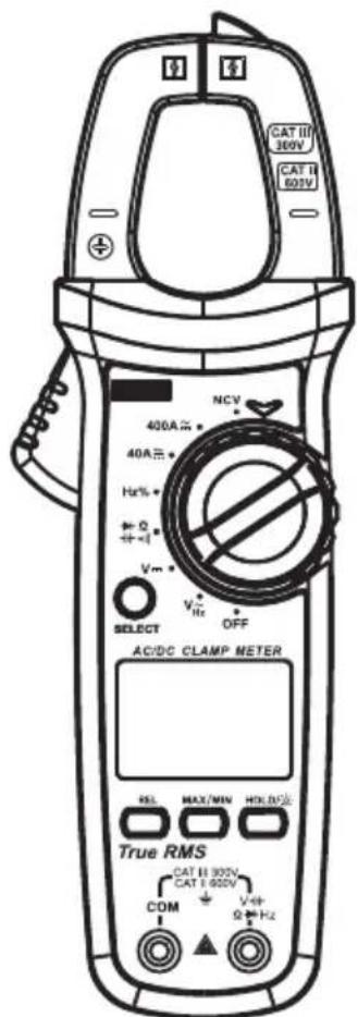
The UT-203R clamp meter is a measuring instrument for measuring DC current, AC current, DC voltage, AC voltage and resistance, as well as performing diode tests and continuity tests. Measurements are carried out with very high accuracy.
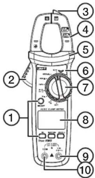
- Function buttons
- Jaw opening lever
- NCV sensor
- Clamp jaws
- Safety collar
- LED indicator
- Function selector
- LCD display
- Test lead input jack (red and positive +)
- Test lead input jack (black and negative -)
Button functions
SELECT
- Press [ SELECT ] to select the function.
- Press [SELECT] to activate the clamp meter if it has gone into standby mode.
HOLD/
- Press and hold the [ HOLD/ ] button for approx. 2 seconds to turn off the backlit display.
MAX/MIN
- Press [ MAX/MIN ] to activate the MAX/MIN measurement function.
- Press and hold in [ MAX/MIN ] to turn off the measurement function.
REL/ZERO
- Press [REL/ZERO] to activate or turn off the REL function.
- Press [REL/ZERO] to save the current measurement for future use. When the LCD display has returned to zero the previous reading will be subtracted from the current reading.
Functions
- Effective voltage, also called RMS measurement (root mean square). The RMS value is used to simplify the calculation of the power in AC circuits.
• Non-contact sensors for voltage testing
• Capacitance and resistance measuring
• Continuity and diode testing - 600 V overvoltage safety protection
Instructions for use
AC or DC current measurement

Disconnect the test leads from the instrument e measuring any current.
natural_image
Technical line drawings of a handheld device with no visible text or symbols- Set the function selector to the desired measuring function.
- Press [SELECT] and select the desired measuring function (or appears on the left of the display).
- Hold the instrument motionless in a firm grip, the measuring sensors are sensitive to vibrations, heat and magnetic fields. Vibrations can cause errors.
- Press [REL/ZERO] to clear the display.
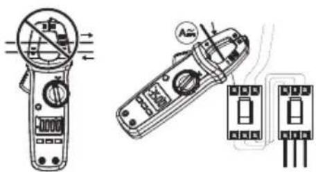
- Open the clamp and enclose one of the conductors, keep the conductor in the centre of the clamp and between the markings on the jaws. Close the jaws of the clamp carefully.
Note: Leave no gap between the jaws of the clamp when measuring. Only measure one conductor at a time; the measurement of several conductors simultaneously can lead to errors. - Read the value: press [HOLD/ -] if you have difficulty seeing the display or if you wish to save the reading.
- Open the jaws of the clamp and move the instrument away from the conductors.
- Press [HOLD/ ] again to exit the measurement mode.
Measuring direct current (DC) or alternating current (AC) (duty cycle)
In order to avoid personal injury or damage to the instrument, do not measure voltages over 600 V DC or 600 V AC RMS using this clamp meter.
-
Set the function selector to the desired measuring function.
-
Connect the black test lead to the negative COM input terminal and
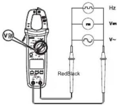
the red test lead to the positive input terminal.
- Connect the tips of both test leads to the circuit.
- Read the displayed value. Press [HOLD/ to save the reading.
- Disconnect the test leads.
Measuring resistance
⚠️ Before measuring the resistance of a circuit, first turn off the power and make sure that any capacitors in the circuit are discharged.
-
Set the function selector to
-
Connect the black test lead to the negative COM input terminal and the red test lead to the positive input terminal.
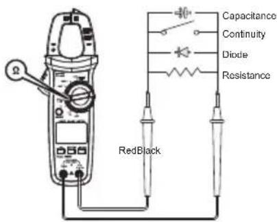
- Connect the tips of both test leads to the circuit.
- Read the displayed value. Press [HOLD/ to save the reading.
- Disconnect the test leads.
Measuring capacitance
Note: Use the REL function to measure capacitance lower than 100 nF.
- Set the function selector to
- Connect the black test lead to the negative COM input terminal and the red test lead to the positive input terminal.
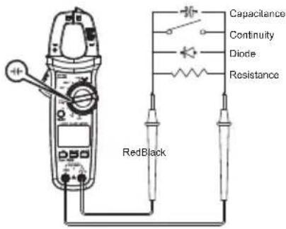
-
Connect the tips of both test leads to the circuit.
-
Read the displayed value. Press [HOLD/] to save the reading.
-
Disconnect the test leads.
Testing for continuity
⚠️ Before measuring the continuity of a circuit, first turn off the power.
-
Set the function selector to •••
-
Connect the black test lead to the negative COM input terminal and the red test lead to the positive input terminal.
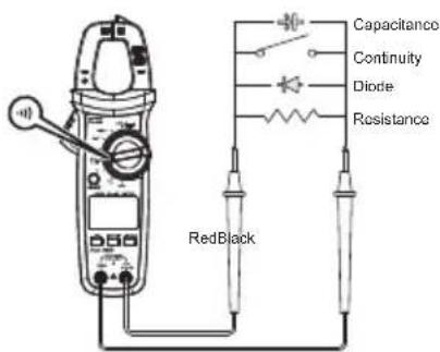
-
Connect the tips of both test leads to the circuit.
-
If the measurement is < 10 the instrument will emit a clear audible signal.
- If the measurement is >31 Ω the instrument will emit no audible signal.
-
If the measurement is between 10 and 31 Ω the instrument will emit an irregular audible signal.
-
Read the displayed value. Press [HOLD/ ] to save the reading.
-
Disconnect the test leads.
Diode testing
⚠️ Before doing a diode test of a circuit, first turn off the power.
-
Set the function selector to
-
Connect the black test lead to the negative COM input terminal and the red test lead to the positive input terminal.
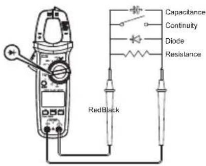
- Connect the test leads across the circuit to be tested.
- Read the displayed value. Press [HOLD/ ];to save the reading.
- Disconnect the test leads.
Non-contact voltage testing
Note: Select between two measuring levels: EFHI and EFLo. The clamp meter is automatically set to EFHI.
- Set the function selector to NCV
- Select EFHI when the test object has a voltage or around 220 V AC 50/60 Hz.
- Select EFLo when the test object has a voltage of around 110 V AC 50/60 Hz.
- Place the non-contact voltage sensor close to the object you are measuring such as a wall socket.
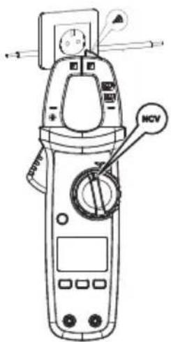
-
Read the displayed value. Detected voltage will be indicated by (—), a buzzer sound and a red light. The higher the voltage, the more (----), will be shown, the louder the buzzer will sound and the brighter the red light will shine. Press [HOLD/※if you want to save the reading.
-
Remove the voltage sensor.
Care and maintenance
Avoid electrical shocks or damage to the meter by making sure it stays away from water.
- Clean the clamp meter using a soft cloth and a mild detergent.
- Repairs must only be carried out by a qualified electrician.
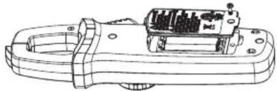
Battery replacement
⚠️ Disconnect the test leads form the test object and the clamp meter and make sure that the clamp is not placed around a conductor before changing the batteries.
Change the batteries when the battery symbol appears on the display.
natural_image
Technical line drawing of a mechanical device with internal components (no text or symbols)- Turn the meter off and remove the test leads.
- Remove the screw holding the battery cover in place.
- Remove the battery cover.
- Take out the old batteries.
- Insert new AAA/LR03 batteries, observing the polarity markings in the battery compartment.
- Replace the battery cover and refit the screw.
Responsible disposal
This symbol indicates that the product should not be disposed of with general household waste. This applies throughout the entire EU. In order to prevent any harm to the environment or health hazards caused by incorrect waste disposal, the product must be handed in for recycling so that
natural_image
Symbol of a trash bin crossed with no visible text or labelsthe material can be disposed of in a responsible manner. When recycling your product, take it to your local collection facility or contact the place of purchase. They will ensure that the product is disposed of in an environmentally sound manner.
Specifications
Frequency range 45–400 Hz
Display LCD display with a max value of 4099
Polarity indication: "Auto" is shown on the display
Out of range indication "OL" or "-OL" is shown on the display
Low battery warning is shown on the display
Batteries AAA/LR03 × 2
Error If the conductor is not placed in the centre of the clamp, an error of ± 1% may occur
Clamp opening 28 mm in diameter
Automatic shut-off After 15 minutes when it has not been used
Measurement category CAT II 600 V CAT III 300 V
Standard compliance EN 61010-1, 61010-2-032/033, and EN 61326-1
Operating temperature/ humidity 0–30 °C (≤ 80 % RH), 30–40 °C (≤ 75 % RH), 40–50 °C (≤ 45% RH)
Storage temperature -20 to +60 °C (≤ 80 % RH)
Dimensions 215 × 63.5 × 36 mm
Weight approx. 235 g with battery
Tångamperemeter
Art.nr 36-8126 Modell UT-203R
natural_image
Technical line drawing of a handheld electrical clamp or power supply device (no text or symbols visible)natural_image
Symbol of a trash bin crossed with no text or numbers, representing waste sorting or disposal (no text present)NORSK
Knappefunksjoner
SELECT
natural_image
Technical line drawing of a handheld electronic device with internal components (no text or symbols)natural_image
Symbol of a trash bin crossed with a diagonal line and a horizontal line, representing no waste or disposal (no text or labels)en tilfredsstillende måte. Når produktet skal kasseres, benytt eksisterende systemer for returhåndtering eller kontakt forhandler. De vil ta hånd om produktet på en miljømessig forsvarlig måte.
Spesifikasjoner
Frekvensområde 45–400 Hz
Skjerm LCD-display med maks verdi på 4099
natural_image
Technical line drawing of a handheld electrical clamp or power supply device (no text or symbols visible)natural_image
Technical line drawings of a remote control device with no visible text or symbolsnatural_image
Technical line drawing of a mechanical device with internal components and mounting holes (no text or symbols)| Measuring range | Resolution Accuracy | |
| 40.0 A 0.01 A | ± (2% + 5) | |
| 400.0 A 0.1 A | ± (2% + 5) | |
Alternating current (AC)
| Measuring range | Resolution Accuracy |
| 40.0 A 0.01 A | ± (2% + 5) |
| 400.0 A 0.1 A | ± (2% + 5) |
DC voltage
| Measuring range | Resolution Accuracy |
| 400.0 M V 0.1 mV ± (0.7 + 3) | |
| 4.000 V 0.001 V ± (0.5 + 2) | |
| 40.00 V 0.01 V ± (0.5 + 2) | |
| 400,0 V 0.1 V ± (0.5 + 2) | |
| 600 V 1 V | ± (0.5 + 2) |
AC voltage
| Measuring range | Resolution Accuracy |
| 4.000 V 0.001 | V ± (1.0 + 5) |
| 40.00 V 0.01 V | ± (0.8 + 5) |
| 400.0 V 0.1 V | ± (0.8 + 5) |
| 600 V 1 V | ± (0.8 + 5) |
Resistance
| Measuring range | Resolution Accuracy | |
| 400.0 Ω | 0.1 Ω ± (1.0 + 2) | |
| 4.0000 Ω | 0.001 KΩ | ± (0.8 + 2) |
| 40.00 Ω | 0.01 KΩ | ± (0.8 + 2) |
| 400.0 Ω | 0.1 KΩ | ± (0.8 + 2) |
| 4.000 M Ω | 0.001 MΩ | ± (2.5% + 5) |
| 40.00 M Ω | 0.01 MΩ | ± (2.5% + 5) |
Capacitance
| Measuring range | Resolution Accuracy | |
| 40.00 nF 0.01 | nF ± (4% + 5) | |
| 400.0 nF 0.1 nF | ± (4% + 5) | |
| 4.000 nF 0.001 | μF ± (4% + 5) | |
| 40.00 μF 0.01 | μF ± (4% + 5) | |
| 400.0 μF 0.1 μF | ± (4% + 5) | |
| 4.000 mF 0.001 | mF ± 10% | |
| 40.00 mF 0.01 | mF ± 10% | |
Continuity
| Measuring range | Resolution | Accuracy |
| 400.0 Ω 0.1 | Ω ≤10Ω: Continuous signal sound ≥31Ω: No signal Median: Unsafe | |
Diode
| Measuring range | Resolution Accuracy |
| 4.000 V 0.001 V Open circuit voltage: 4 VSilicon P-N junction diode: 0.5–0.8 V | |
Sverige
Customer Service e-mail: customerservice@clasohlson.co.uk
Returns Address Clas Ohlson Ltd, The Archway,
7-9 West Street, Reading, Berkshire, RG1 1TT
Deutschland
Kundenservice
E-Mail: kundenservice@clasohlson.de
Homepage
www.clasohlson.de
- UNI-T UT-203R Digital Clamp Meter
- Digital Clamp Meter
- Safety
- Warning:
- Symbols
- Product description
- Button functions
- SELECT
- HOLD/
- MAX/MIN
- REL/ZERO
- Functions
- Instructions for use
- AC or DC current measurement
- Measuring direct current (DC) or alternating current (AC) (duty cycle)
- Measuring resistance
- Measuring capacitance
- Testing for continuity
- Diode testing
- Non-contact voltage testing
- Care and maintenance
- Battery replacement
- Responsible disposal
- Specifications
- Tångamperemeter
- Knappefunksjoner
- Spesifikasjoner
- Sverige
- Deutschland
Brand : Uni-T
Model : UT-203R
Category : Multimeter