ISD-A33S - Security Camera Ikegami - Free user manual and instructions
Find the device manual for free ISD-A33S Ikegami in PDF.


| Product Type | Outdoor Security Camera |
| Image Sensor | 1/3.2-inch DPS CMOS |
| Effective Pixels | Approx. 1,230,000 (1280 x 960) |
| Horizontal Resolution | 700 TV lines |
| Minimum Illumination | 0.1 lux (color), 0.02 lux (B/W) at F1.4 |
| Signal-to-Noise Ratio | More than 50 dB |
| Wide Dynamic Range | Built-in Hyper WDR |
| Day/Night Switching | True Day/Night with auto or manual |
| White Balance | ATW, PUSH, PUSHLOCK, MANUAL |
| Lens Type | Varifocal lens (f2.8-11.0mm or f9.1-21.5mm) |
| Video Output | VBS 1.0 Vp-p / 75 ohms (BNC), MON.OUT |
| Power Requirement | DC 12V (10.5-15V) or AC 24V ±10% (50/60 Hz) |
| Power Consumption | Approx. 2.0 W |
| Operating Temperature | -10°C to +50°C (RH 30% to 90%) |
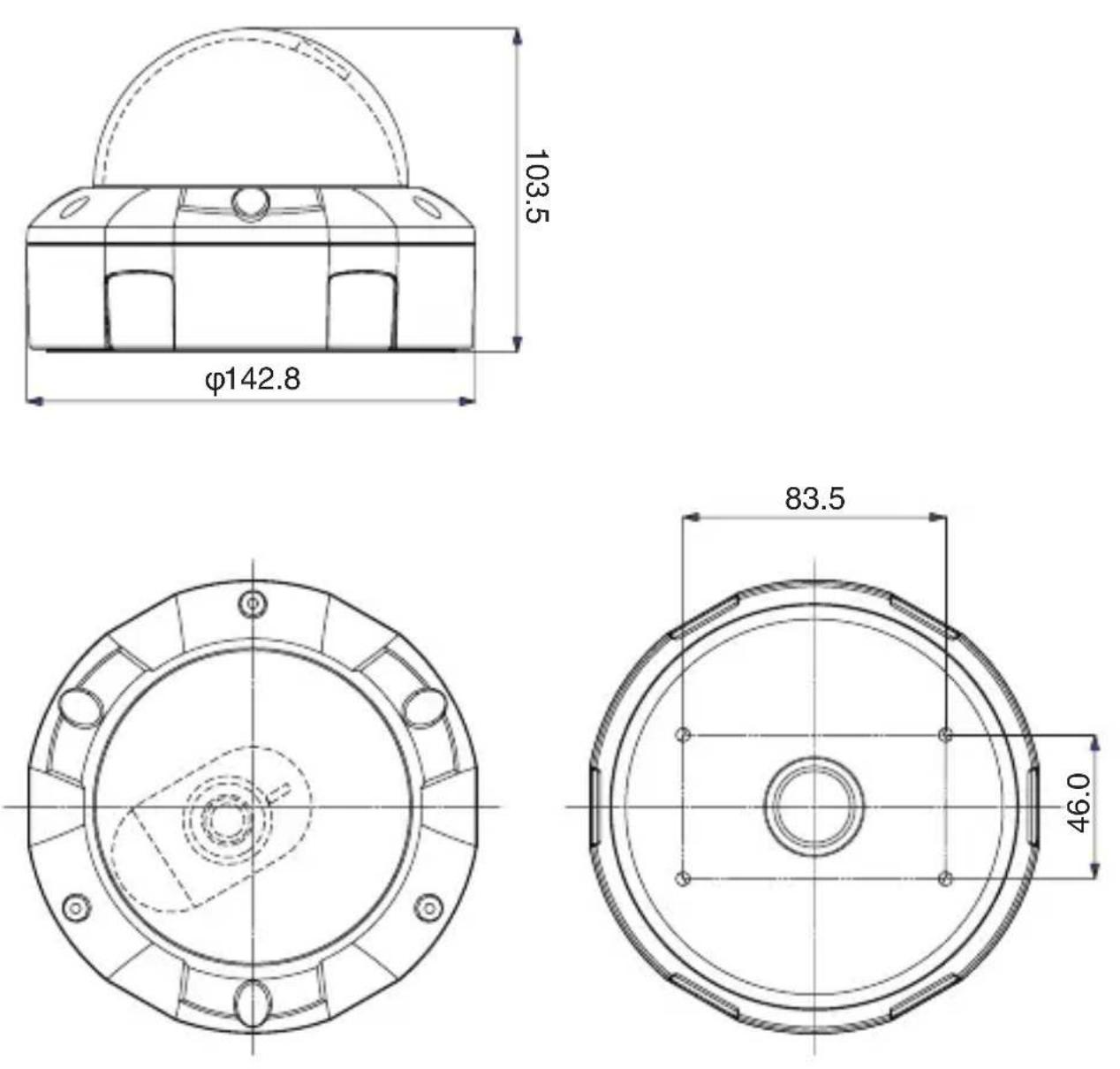
| Dimensions (Diameter x Height) | 142.8 mm x 103.5 mm |
| Weight | Approx. 990 g |
| Dome Cover | Vandal-resistant polycarbonate |
| Privacy Mask | Up to 16 areas, adjustable color and transparency |
| Camera ID | 2 lines, up to 26 alphanumeric characters |
| Digital Noise Reduction | Built-in, selectable Y/C mode |
| Mounting | Ceiling or wall, with triaxial adjustment |
| Accessories Included | Manual, mounting screws, L-form wrench, MON.OUT harness, rubber gasket |
Frequently Asked Questions - ISD-A33S Ikegami
User questions about ISD-A33S Ikegami
0 question about this device. Answer the ones you know or ask your own.
Ask a new question about this device
Download the instructions for your Security Camera in PDF format for free! Find your manual ISD-A33S - Ikegami and take your electronic device back in hand. On this page are published all the documents necessary for the use of your device. ISD-A33S by Ikegami.
USER MANUAL ISD-A33S Ikegami
text_image
eco products IkegamiOUTDOOR USE WARNING
WARNING – TO PREVENT FIRE OR ELECTRIC SHOCK, DO NOT EXPOSE THIS APPLIANCE TO RAIN OR MOISTURE.
The apparatus shall not be exposed to dripping or splashing and that no objects filled with liquids, such as vases, shall be placed on the apparatus.
Ikegami
Ikegami Tsushinki Co., Ltd
Thank you for choosing this Ikegami Hyper Wide Dynamic DPS Dome Camera. Please read this Instruction Manual carefully to keep your Ikegami camera at peak performance for longer service period.
This DPS camera is equipped with 1/3.2" DPS CMOS sensor, which has an extremely wide light dynamic range and a lot of useful facilities and functions in a smart dome shape to allow for a wide range of uses in many different applications.
This Ikegami product is made of ECO friendly components based upon the Company policy and corporate social responsibility to contribute towards the Global Environmental Solution for energy conservation and environmental sustainability, all the components used in this product are Non-hazardous, Toxic Free, Non-Lead and conform with Japan's Green Product regulation, EU's RoHS directive and other Environmental and hazardous chemical substances related regulations and laws.
Contents
Page
- Handling Precautions....E-1
- General....E-1
- Features.....E-2
- Camera Installation ....E-3
4-1. Pre-work before installation.....E-3
4-2. Mounting the camera (Ceiling)....E-3
4-3. Mounting the camera (Wall) ......E-3
- Name of each section and its function....E-4
- Connections.....E-6
6-1. Power cable ......E-6
6-2. Video output cable (BNC)......E-6
6-3. Test monitor output (MON.OUT) E-6
- Angle and Lens adjustment.....E-7
7-1. Angle adjustment.....E-7
7-2. Vari-focal lens adjustment....E-7
- Operating Procedure....E-8
8-1. User Setup....E-8
8-2. Names and functions of the setup buttons.....E-8
8-3. Setup mode Procedures....E-8
-
Warranty and after-sale service....E-16
-
Specifications ......E-17
- External Appearance
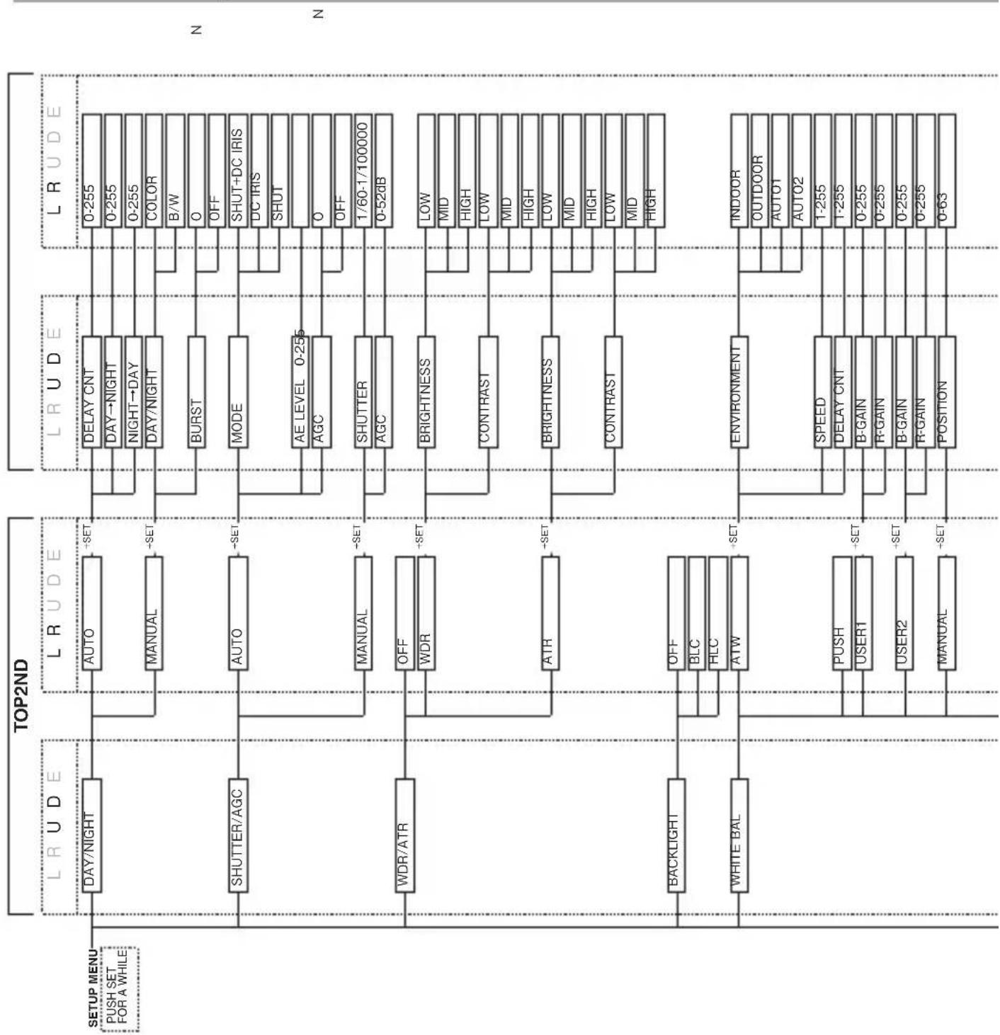
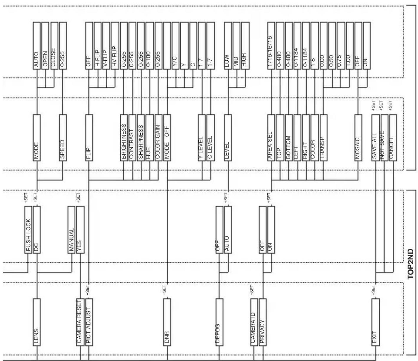
- Setup Flow Chart
The exclamation point within an equilateral triangle is intended to alert the user to the presence of important operating and maintenance (servicing) instructions in the literature accompanying the appliance.
NOTE:
This equipment has been tested and found to comply with the limits for a Class A digital device, pursuant to part 15 of the FCC Rules. These limits are designed to provide reasonable protection against harmful interference when the equipment is operated in a commercial environment. This equipment generates, uses, and can radiate radio frequency energy and, if not installed and used in accordance with the instruction manual, may cause harmful interference to radio communications. Operation of this equipment in a residential area is likely to cause harmful interference in which case the user will be required to correct the interference at his own expense.
CAUTION;
ANY CHANGES OR MODIFICATIONS NOT EXPRESSLY APPROVED BY THE PART RESPONSIBLE FOR COMPLIANCE COULD VOID THE USERS AUTHORITY TO OPERATE THE EQUIPMENT.
Instructions for Disposal of Electrical and Electronic Equipment in Private Households
Disposal of used Electric and Electronic Equipment (Applicable in the European Union and other European countries with separated waste disposal and collection methods)
This symbol on the product, or in the related documents in the package, indicates that this product shall not be treated as normal household waste. Instead, it should be taken to a proper applicable collection point or depot for the recycling of electric and electronic equipment.
By ensuring this product is disposed of correctly, you will help prevent possible negative consequences for the environment and human health, which could otherwise be caused by inappropriate waste handling of this product. The recycling of materials will help to conserve natural resources.
For more detailed information about recycling of this product, please contact your local city authority, your household waste disposal service or the place where you purchased the product.
IMPORTANT SAFETY INSTRUCTIONS
1) Read these instructions.
2) Keep these instructions.
3) Heed all warnings.
4) Follow all instructions.
5) Do not use this apparatus near water.
6) Clean only with a dry cloth.
7) Do not block any of the ventilation openings. Install in accordance with the manufacturer's instructions.
8) Do not install near any heat sources such as radiators, heat registers, stoves, or other apparatus (including amplifiers) that produce heat.
9) Do not defeat the safety purpose of the polarized or grounding type plug. A polarized plug has two blades with one wider than the other. A grounding type plug has two blades and a third grounding prong. The wide blade or the third prong is provided for your safety. When the provided plug does not fit into your outlet, consult an electrician for replacement of the obsolete outlet.
10) Protect the power cord from being walked on or pinched particularly at plugs, convenience receptacles, and the point where they exit from the apparatus.
11) Only use the attachments/accessories specified by the manufacturer.
12) Use only with a cart, stand, tripod, bracket, or table specified by the manufacturer, or sold with the apparatus. When a cart is used, use caution when moving the cart/apparatus combination to avoid injury from tip-over.

natural_image
Symbolic illustration of a person climbing a ladder inside a circle (no text or symbols)13) Unplug this apparatus during lightning storms or when unused for long periods of time.
14) Refer all servicing to qualified service personnel. Servicing is required when the apparatus has been damaged in any way, such as power supply cord or plug is damaged, liquid has been spilled or objects have fallen into the apparatus, the apparatus has been exposed to rain or moisture, does not operate normally, or has been dropped.
15) CAUTION - These servicing instructions are for use by qualified service personnel only. To reduce the risk of electric shock, do not perform any servicing other than that contained in the operating instructions unless you are qualified to do so.
1. Handling Precautions
- Do not use the camera where the ambient temperature drops below -10^ or rises above +50^ . The images and component parts may be adversely affected or the camera may not function correctly.
- Do not open the case of the camera, unless it is absolutely necessary for setup or installation because there are precision electrical and electronic components inside and accident may result.
- Be sure to turn off the power before installing or making connections.
- Be careful not to drop or give a strong shock to the camera while transporting it.
- Do not touch the image sensor
- Do not orientate the camera directly towards the sun.
- Because of the digital image device characteristics, images may look unnatural at high temperatures, this does not mean the camera is faulty.
2. General
This color camera is provided with a 1/3.2-inch DPS CMOS sensor. The camera features a hyper wide light dynamic range, high sensitivity and high resolution in a vandal resistant clear dome with many useful features such as back-light compensation by which you can assign desired spots to have proper Back Light Compensation for a maximum of two points, Automatic iris control, various modes of automatic white balancing, camera setup and control is also possible locally with the supplied setup adaptor and this setup data is stored in the built-in non-volatile memory. This TV camera is best suited for general surveillance purposes, from single camera operation to large scale integrated systems for visual information management.
3. Features
(1) All-in-One Ergonomic Vandal Resistant Dome camera This dome camera comes equipped with a strong poly-carbonate clear dome with a sturdy aluminium plinth of IP66 class Vandal resistant performance.
(2) Integrated unit with triaxial adjustment varifocal lens in a single unit This is an integrated type design featuring a varifocal lens. Because it can operate with triaxial adjustment, even when attached to a wall, it can be adjusted to an arbitrary imaging range.
(3) Hyper Wide Light Dynamic Range (Hyper WDR)
The Wide dynamic function provides for very effective compensation of high light and dark areas in screen. This situation may occur generally outside or viewing from indoor to outside scenes. Even in large light fluctuations, bright-and-dark objects can be captured and viewed clearly with a natural color.
(4) Automatic White Balance
Thanks to the automatic tracking white balance control (ATW), the white balance control adjusts itself no matter how great the subject's color temperature fluctuates. Also extended coverage function as ATW ex is provided for specific lighting conditions.
(5) High-quality picture and high resolution
The camera is designed for smear-free imaging and low noise. The well-designed DSP, Digital Signal Processor, effectively enhances details, which achieves crisp and sharp images with a high signal-to-noise ratio. The high resolution of a horizontal resolution of 700 TV lines is assured.
(6) High sensitivity
Various modes of Automatic Gain control (AGC) are available to finely adjust the camera settings depending on the subject's illumination conditions.
4. Camera Installation
4-1. Pre-work before installation
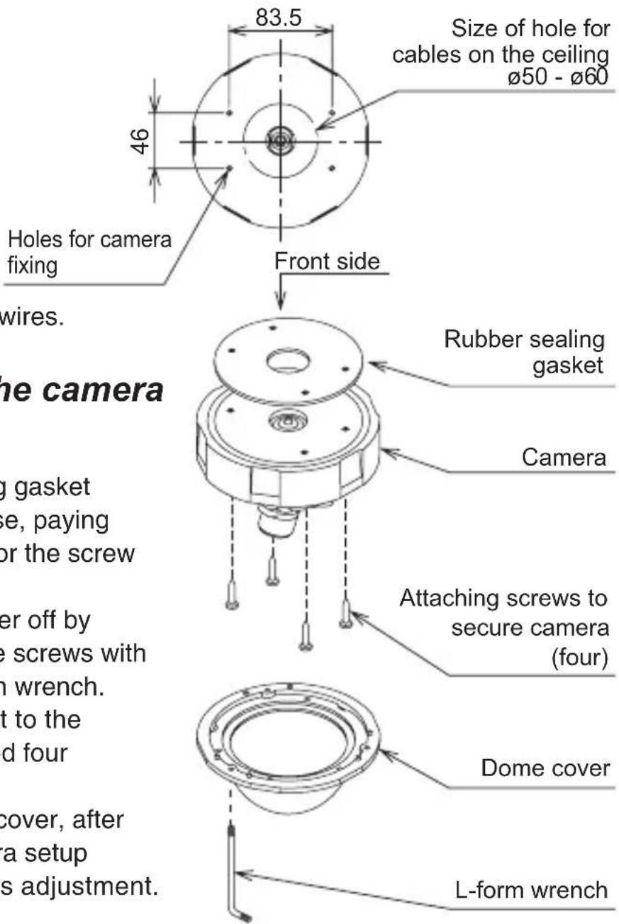
Make holes for cables and to fix a camera.
For the hole for cable, a diameter of the opening should be at least 50mm to 60mm. Please make it with utmost care not to give damage to wires.
text_image
83.5 Size of hole for cables on the ceiling Ø50 - Ø60 46 Holes for camera fixing Front side Rubber sealing gasket Camera Attaching screws to secure camera (four) Dome cover L-form wrench wire. the camera gasket se, paying or the screw er off by e screws with n wrench. t to the d four cover, after a setup s adjustment.4-2. Mounting the camera (Ceiling)
- Put a rubber sealing gasket on the housing base, paying attention to allow for the screw holes.
- Take the dome cover off by loosening the three screws with the supplied L-form wrench.
- Install the main unit to the ceiling with supplied four screws.
- Replace the dome cover, after making final camera setup selections and lens adjustment.
4-3. Mounting the camera (Wall)
The way of installation is the almost same as to a ceiling.
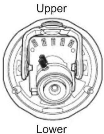
Install the main unit so that the switch becomes upper side as shown in the illustration right and set the "FLIP" in the setup menu to "V-FLIP".
text_image
Upper Lower5. Name of each section and its function

text_image
Technical diagram of a mechanical assembly with numbered components and labeled parts in Chinese① Camera fixing screws (base rotation)
These are screws to lock the camera in the desired rotation position.
Fix these screws after setting the viewing position.
② Lens fixing screws (elevation)
These are screws to fix the camera in the desired elevation position.
Fix these screws after setting the viewing position.
③ Vari-focal lens
Can be used with flexible angle of view using varifocal lens.
④ Switches for camera setup
Refer to Section 8 (Operating Procedure)
⑤ Test monitor output
Connect accessory MON.OUT output harness.
⑥ Power cable
This is a power cable. Non-polarity AC24V (AC 21.6V \~ 26.4V) or DC12V has to be connected. Check the power voltage from the external power supply before applying power to the camera.
* This installation should be made by a qualified service person and should conform to all local codes.
⑦ Video Output cable (BNC)
This is the output of video signal. Connect this to a monitor or switcher.
⑧ Fixing holes (four)
⑨ Housing base
⑩ Dome Cover
6. Connections
Be sure not to apply power before making connections.
6-1. Power cable
Use DC12V (10.5V to 15V), or AC24V ( ± 10%) in both 60Hz and 50Hz.
* This installation should be made by a qualified service person and should conform to all local codes.
6-2. Video output cable (BNC)
This is a video output terminal. To be use an ordinary video output, for monitors, or switcher.
6-3. Test monitor output (MON.OUT)
- Image output terminal used when installing the camera.
- By using the accessory cable to connect to the VIDEO IN of the monitor or the image input terminal, it is easier to carry out positioning and focusing.
7. Angle and Lens adjustment
7-1. Angle adjustment
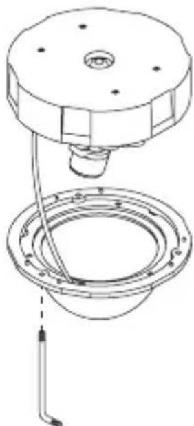
Before doing this, the dome cover has to be removed.
- Remove the dome cover
This is done by loosening the three fixing screws of the dome cover, by the supplied L-form wrench.
Note: When imaging in a horizontal direction, the black section of the dome cover may be imaged so that part of the image is missing. Adjust the angle of vision in a horizontal direction so that the dome cover is not imaged.
natural_image
Technical line drawing of a mechanical assembly with a circular component and ring (no text or symbols)7-2. Vari-focal lens adjustment
To re-direct lens, loosen the lens fixing screws for rotation and for elevation. Adjust the zoom knob for framing and angle, and a focus knob for focusing. Using those two knobs, adjust the lens to have desired framing, angle and focal point. Repeat this procedure a couple of times, so that you may achieve the best result.
Once the desired settings have been achieved, tighten the screws to fix the position.

text_image
Zoom knob Focus knob8. Operating Procedure
8-1. User Setup
This dome camera is provided with user setup function for picture quality, and camera ID. The setup menu is a tree type on-screen-display.
When installing the camera it is possible to set up the various functions.
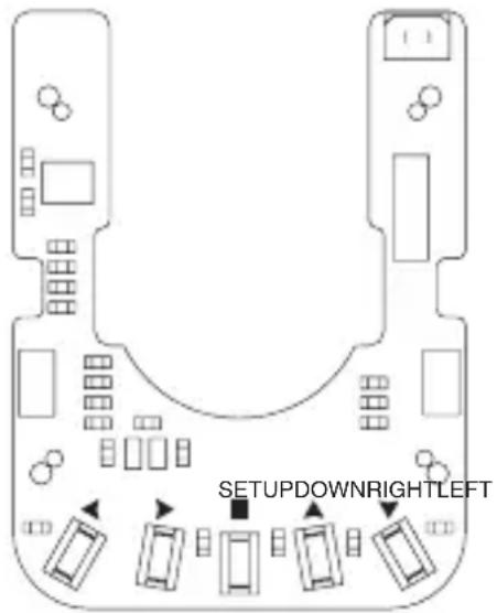
8-2. Names and functions of the setup buttons
text_image
SETUPDOWNRIGHTLEFT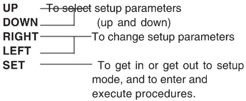
flowchart
graph TD
    A["UP"] --> B["To select setup parameters"]
    C["DOWN"] --> D["(up and down)"]
    E["RIGHT"] --> F["To change setup parameters"]
    G["LEFT"] --> H["To get in or get out to setup mode, and to enter and execute procedures."]
    I["SET"] --> J["To get in or get out to setup mode, and to enter and execute procedures."]
* To get into Setup mode, hold SET button more than 2 seconds.
8-3. Setup mode Procedures
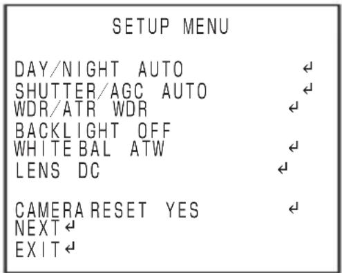
Hold down the SET button longer than 2 seconds, and the setup menu screen at left appears on screen. A highlighted item is now selected. Use the LEFT/RIGHT buttons to change the selection items.
8-3-1. SETUP MENU 1/2
* The setting is not saved unless the menu is finished from EXIT.
text_image
SETUP MENU DAY/NIGHT AUTO SHUTTER/AGC AUTO WDR/ATR WDR BACKLIGHT OFF WHITE BAL ATW LENS DC CAMERA RESET YES NEXT← EXIT←(1) DAY/NIGHT
Selecting Day or Night is available.
① AUTO
The image is automatically switched between high-quality color image for the day and highly-sensitive monochrome image for the night.
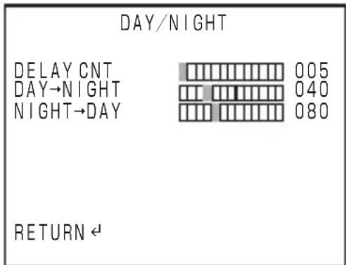
Pressing the E button here opens the right-side window.
• DELAY CNT
Changing the Day/Night switching speed is available.
Switching speed slows down as the number becomes larger.
· DAY → NIGHT
Changing the sensitivity at the timing of switching from color to monochrome is available. Switching
takes place in a brighter environment as the number becomes larger.
• NIGHT → DAY
Changing the sensitivity at the timing of switching from monochrome to color is available. Switching takes place in a brighter environment as the number becomes larger.
② MANUAL
It is a setting for manual switching between Color/Monochrome.
Pressing the E button here opens the right-side window.
• DAY/NIGHT
It sets Color/Monochrome.
• BURST
It sets the burst signal to the video.
It selects a shutter speed and a gain mode.
① AUTO
It automatically adjust the sensitivity Pressing the E button here opens the right-side window.
- MODE
Setting whether the video level adjustment is controlled by the DC iris or by the shutter is available.
- AE LEVEL
It adjusts the brightness of the entire video.
It becomes brighter as the number becomes larger.
- AGC
Setting ON/OFF of automatic video adjustment by gain is available.
② MANUAL
Setting the shutter speed and the gain value manually are available.
- SHUTTER
Changing the shutter speed to any desired value is available. The entire video becomes brighter as the number becomes larger.
- AGC
Changing the gain value to any desired value is available. The entire video becomes brighter as the number becomes larger.
(3) WDR/ATR
Changing the wide dynamic range is available. Select an appropriate value while watching the actual scene.
① WDR
Adjusting the wide dynamic range is available.
• BRIGHTNESS
Adjusting the brightness of the entire video is available.
- CONTRAST
Adjusting the contrast is available.
② ATR
• BRIGHTNESS
Adjusting the brightness of the entire video is available.
- CONTRAST
Adjusting the contrast is available.
(4) BACKLIGHT
Setting the blacklight correction and light source correction functions are available.
AUTO SETUP
HIGH LUMINANCE
MODE SHUT+DC IRIS
AE LEVEL 050
LOW LUMINANCE
AGC ON
RETURN ←
① HLC
It is a function to increase the visibility of the surrounding area by using a mask when a light source exists in the video.
② BLC
It is a blacklight correcting function.
(5) WHITE BAL
Setting a white balance is available.
① ATW
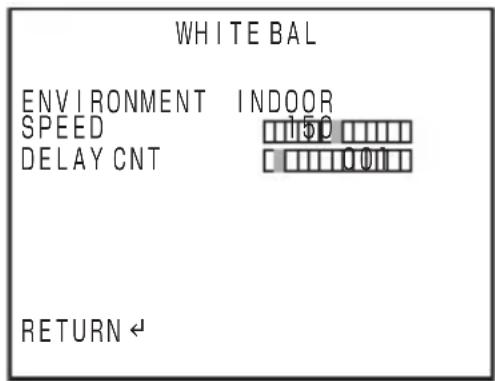
It is a setting that automatically judge the condition of playing video and conducts adjustments. Pressing the E button here opens the right-side window.
• ENVIRONMENT
text_image
WHITE BAL ENVIRONMENT INDOOR SPEED 150 DELAY CNT 001 RETURN ←INDOOR••ATW mode suitable for indoor installation
OUTDOOR…ATW mode suitable for outdoor installation
AUTO...The camera automatically determines if it is indoor or outdoor.
- SPEED
It decides the speed necessary for white balance adjustment.
- DELAY CNT
It sets the standby time for readjustment of white balance when switching takes place. The condition is more stable as the number becomes larger. However, the reaction speed decreases.
② PUSH
It draws any colors.
The colors may look light depending on subjects.
③ USER1
Manual fixed white balance 1
④ USER2
Manual fixed white balance 2
⑤ MANUAL
Adjust by moving the position to the left and the right. The left side increases blue, and the right side increases red.
⑥ PUSH LOCK
Set the white balance from the subject you are shooting. If the light source is changed after this setting, color deviation can occur.
(6) LENS
Setting that corresponds to the attached lens is available.
① DC
Use it in case of the DC iris lens.
- MODE
Selecting either one of automatic control, open, or close is available for diaphragm.
- SPEED
This is a setting available only when the MODE is automatic control. Changing the opening/closing speed of diaphragm is available.
(7) CAMERA RESET
It returns the setup contents to the default setting before shipping from the factory.
(8) NEXT
Switching to the next page is available.
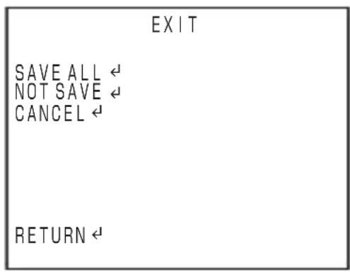
(9) EXIT
Pressing the E button here opens the right-side window.
- SAVE ALL
It saves all of the changed settings and ends the menu.
- NOT SAVE
It ends the menu without changing.
• CANSEL
It returns the settings to the ones
previously saved and returns to the menu.
- RETURN
It returns to the menu.
text_image
EXIT SAVE ALL ← NOT SAVE ← CANCEL ← RETURN ←8-3-2. SETUP MENU 2/2
* The setting is not saved unless the menu is finished from EXIT.
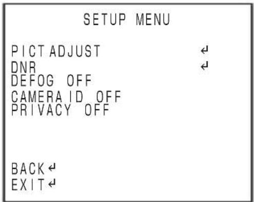
text_image
SETUP MENU PICT ADJUST DNR DEFOG OFF CAMERAID OFF PRIVACY OFF BACK EXIT(1) PICT ADJUST
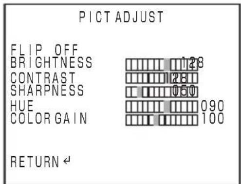
Video inversion and adjustments of brightness, contrast, sharpness, hue, and intensity are available.
Selecting PICT ADJUST and pressing the E button opens the right-side window.
① FLIP
It flips the video vertically and horizontally.
② BRIGHTNESS
It adjusts the brightness of the video.
③ CONTRAST
It adjusts the contrast of the video.
④ SHARPNESS
It adjusts the edge intensity of the video.
⑤ HUE
It adjusts the tint.
⑥ COLOR GAIN
It adjusts the color intensity.
(2) DNR (Digital Noise Reduction)
Detailed setting of the noise reduction is available.
Selecting DNR and pressing the E button sets the following contents.
① MODE
It selects the noise reduction type. Y is the mode for object contour, C is the mode for color tone, and Y/C corresponds to both.
②Y LEVEL
It decides the intensity of noise reduction.
③ C LEVEL
It decides the intensity of noise reduction.
text_image
PICT ADJUST FLIP_OFF BRIGHTNESS CONTRAST SHARPNESS HUE COLOR GAIN 128 128 050 090 100 RETURN ←(3) DEFOG
It is used when the entire video looks foggy.
The LEVEL consists of LOW, MID, HIGH. Select one according to the situation.
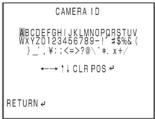
(4) CAMERA ID
The screen can display 26 characters x 2 lines.
① OFF
② ON
● ID character setting
Pressing the E button while
CAMERA ID is ON opens the screen on the right.
- Alphabets, numeral figures, symbols When the E button is pressed while these items are selected, letters are added to the ID.
- Arrow
When the E button is pressed while an arrow is selected, the cursor moves to the specified position.
- CLR
It erases the characters selected with a cursor. - POS
It sets the CAMERA ID display position. Pressing URLD moves the cursor up and down, and right and left. Pressing the E button finalizes the condition.
(5) PRIVACY
The maximum of 16 channels can be set for the privacy mask.
Setting mask color, intensity, and size are available.
TOP and BUTTOM decide the vertical range, and RIGHT and LEFT decides the horizontal range.
text_image
CAMERA ID ABCDEFGHIJKLMNOPQRSTUVWXYZ0123456789-!" #$%& ( ) _, ¥: ;<=>?@\ ^*. x+/ ←→ ↑↓ CLR POS ← RETURN ←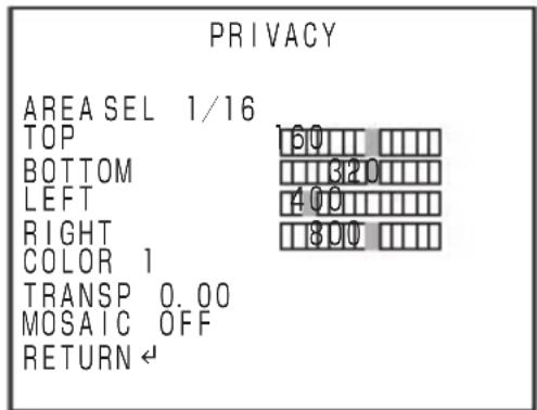
text_image
PRIVACY AREA SEL 1/16 TOP BOTTOM LEFT RIGHT COLOR 1 TRANSP 0.00 MOSAIC OFF RETURN ←① AREA SEL
It decides the mask ch. to change the setting.
② TOP
It decides the upper position of the privacy mask area.
③ BOTTOM
It decides the lower position of the privacy mask area.
④ LEFT
It decides the left side position of the privacy mask area.
⑤ RIGHT
It decides the right side position of the privacy mask area.
⑥ COLOR
Changing the mask color is available.
⑦ TRANSP
It decides the shades of the mask color.
⑧ MOSAIC
It selects whether or not to apply mosaic process within the mask area.
9. Warranty and after-sale service
A warranty accompanies this product. Read and fill out the warranty card that you have received at your dealer. Keep this card in a safe place.
- Please consult Ikegami Electronics (U.S.A.) Inc. or Ikegami Electronics (Europe) GmbH or your dealer for full warranty information. Your dealer will repair or replace free of charge within the warranty period according to the warranty coverage.
- For repairs after the expiration of the warranty period, consult your dealer or sales representative. It will first be judged whether the fault is repairable or not. Charged servicing will then be made upon request of the user.
- Before you ask for servicing, please ensure you read the Instruction Manual. If the unit still fails, take note of the model number, date of purchase, problem, etc. in detail, and inform your dealer or sales representative.
- If you have questions about the after-sale service, contact your dealer or sales representative.
* We suggest you ask for preventive inspection as soon as possible.
10. Specifications
(1) Image Sensor: 1/3.2-inch DPS CMOS sensor
(2) Pixel Number: Approx. 1,230,000 pixels, 1280(H)×960(V)
(3) Scanning system: 525 TV lines / 59.94Hz, 2 : 1 interlace
(4) Sync system: Internal synchronization (Crystal-lock)
(5) Video output: VBS 1.0Vp-p/75 ohms
MON.OUT 1.0Vp-p/75 ohms
(6) Day/Night switching: True Day/Night
(7) Resolution: Horizontal; 700 TV lines
(8) S/N ratio: Over 50 dB (p-p/rms)
(9) Minimum object illumination: 0.1Lx/F1.4
(DAY/NIGHT COLOR;VBS output:50%)
0.02Lx/F1.4
(DAY/NIGHT B/W;VBS output:50%)
(10) Wide Dynamic Range: Built-in
(11) AGC: ON/OFF (Variable) Selectable
(12) White Balance Control: ATW(Indoor/Outdoor/AUTO1/AUTO2)/PUSH/
PUSHLOCK/MANUAL, Selectable
(13) Private Mask Setting: Built-in. Up to 16 areas
(14) Digital Noise Reduction: Built-in, On or OFF, Selectable
(15) Camera ID: 2 Line, up to 26 characters
(alphanumeric and symbols)
(16) Local Setup: Camera ID, AGC ON/OFF, ATW/PUSH/
PUSHLOCK/MANUAL selection and
adjustment,Wide Dynamic Range level,Back
Light Compensation On or Off,DNR ON/
OFF,Chroma level,P.Mask setting
(17) Video Flip function: Built-in. up or down, right or left, up and down or right and left
(18) Lens: Built-in. Vari-focal Lens:
f2.8mm \~ 11.0mm
f9.1mm \~ 21.5mm
(19) Power Requirement: DC 12 V (+10.5V \~ + 15V)
AC 24 V ± 10% (50/60Hz)
(20) Power Consumption and Current: Approx. 2.0 watts
(21) Operating Temperature and Relative humidity: -10 to +50°C, RH 30% to 90%
-10 to +50°C, RH 30% to 90%
(No Condensation)
(22) Dome cover: Vandal Resistance type
(23) Size (Diameter & Height): ∅142.8mm x 103.5mm
(excluding protrusions)
(24) Weight: Approx. 990 g
(25) Input/output connectors: • VIDEO OUT: BNC
• Power input: open-ended wires
• MON.OUT Connector output
(26) Supplied accessories: Instruction Manual: 1
Screw: 1
MON.OUT output harness: 1
Attaching screws to secure camera: 4
Rubber Gasket: 1
Rubber Cap: 1
L-form wrench: 1
Special wrench: 1
* Specifications and design are subject to change for product improvements without notice.
natural_image
Symbolic illustration of a person climbing a ladder inside a circle (no text or symbols)natural_image
Technical line drawing of a mechanical component with no visible text or symbolsInferior
text_image
Technical diagram of a mechanical assembly with numbered components and labeled parts in Chinesenatural_image
Technical line drawing of a mechanical assembly with a central hub and circular base (no text or symbols)Setting ON/OFF of automatic video adjustment by gain is available.
② MANUAL
(2) DNR (Digital Noise Reduction)
TOP and BUTTOM decide the vertical range, and RIGHT and LEFT decides the horizontal range.
① AREA SEL
11. External Appearance
12. Setup Flow Chart
flowchart
graph TD
    A["TOP2ND"] --> B["L RUDE"]
    B --> C["DAY/NIGHT"]
    B --> D["SHUTTER/AGC"]
    B --> E["WDR/ATR"]
    B --> F["BACKLIGHT"]
    B --> G["WHITE BAL"]
    H["L RUDE"] --> I["DET"]
    H --> J["MANUAL"]
    H --> K["AUTO"]
    H --> L["MANUAL"]
    H --> M["OFF"]
    H --> N["WDR"]
    H --> O["ATR"]
    H --> P["SET"]
    H --> Q["BRIGHTNESS"]
    H --> R["CONTRAST"]
    H --> S["BRIGHTNESS"]
    H --> T["CONTRAST"]
    H --> U["SET"]
    H --> V["SET"]
    H --> W["SET"]
    H --> X["SET"]
    H --> Y["SET"]
    H --> Z["SET"]

    subgraph Top2ND
        AA["0-255"]
        AB["0-255"]
        AC["0-255"]
        AD["COLOR"]
        AE["B/W"]
        AF["O"]
        AG["OFF"]
        AH["SHUT+DC IRIS"]
        AI["DC IRIS"]
        AJ["SHUT"]
        AK["O"]
        AL["OFF"]
        AM["1/60-1/100000"]
        AN["0-52dB"]
        AO["LOW"]
        AP["MID"]
        AQ["HIGH"]
        AR["LOW"]
        AS["MID"]
        AT["HIGH"]
        AU["LOW"]
        AV["MID"]
        AW["HIGH"]
        AX["LOW"]
        AY["MID"]
        AZ["HIGH"]
        BA["INDOOR"]
        BBOUTDOOR
        BC["AUTOT"]
        BD["AUTO2"]
        BE["1-255"]
        BF["1-255"]
        BG["0-255"]
        BH["0-255"]
        BI["0-255"]
        BJ["0-255"]
        BK["PUSH"]
        BL["PUSH1"]
        BM["PUSH2"]
        BN["PUSH1"]
        BO["PUSH2"]
        BP["PUSH1"]
        BQ["PUSH2"]
        BR["PUSH1"]
        BS["PUSH2"]
        BT["PUSH1"]
        BU["PUSH2"]
        BV["PUSH1"]
        BW["PUSH2"]
        BX["PUSH1"]
        BY["PUSH2"]
        BZ["PUSH1"]
        CA["PUSH2"]
        CB["PUSH1"]
        CC["PUSH2"]
        DD["PUSH1"]
        DE["PUSH2"]
        FD["PUSH1"]
        DG["PUSH2"]
        DH["PUSH1"]
        DI["PUSH2"]
        DJ["PUSH1"]
        DK["PUSH2"]
        DL["PUSH1"]
        DV["PUSH2"]
        DW["PUSH1"]
        DX["PUSH2"]
        DB["PUSH1"]
        DC["PUSH2"]
        DVP["PUSH1"]
        DVQ["PUSH2"]
    end

    subgraph BottomTop
        B
        C
        D
        E
        F
        G
        H
        I
        J
        K
        L
        M
        N
        O
        P
        Q
        R
        S
        T
        U
        V
        W
        X
        Y
        Z
    end
flowchart
graph TD
    A["LENS"] --> B["PUSH LOCK"]
    B --> C["DC"]
    C --> D["+SET"]
    D --> E["MODE"]
    E --> F["AUTO"]
    E --> G["OPEN"]
    E --> H["CLOSE"]
    A --> I["SPEED"]
    I --> J["0-255"]
    K["CAMERA RESET"] --> L["MANUAL"]
    L --> M["YES"]
    M --> N["+SET"]
    N --> O["FLIP"]
    O --> P["OFF"]
    Q["PICT ADJUST"] --> R["+SET"]
    R --> S["DNR"]
    S --> T["+SET"]
    T --> U["BRIGHTNESS"]
    U --> V["CONTRAST"]
    V --> W["SHARPNESS"]
    W --> X["HUE"]
    X --> Y["COLOR GAIN"]
    Y --> Z["MODE OFF"]
    Z --> AA["Y/C"]
    Z --> AB["Y"]
    Z --> AC["C"]
    T --> AD["Y LEVEL"]
    AD --> AE["C LEVEL"]
    AE --> AF["1-7"]
    T --> AG["LEVEL"]
    AG --> AH["LOW"]
    AG --> AI["MID"]
    AG --> AJ["HIGH"]
    AK["DEFOG"] --> AL["OFF"]
    AL --> AM["AUTO"]
    AM --> AN["-SET"]
    AN --> AO["LEVEL"]
    AO --> AP["LOW"]
    AO --> AQ["MID"]
    AO --> AR["HIGH"]
    AS["CAMERA ID"] --> AT["+SET"]
    AT --> AU["OFF"]
    AU --> AV["ON"]
    AV --> AW["-SET"]
    AW --> AX["AREA SEL"]
    AX --> AY["TOP"]
    AY --> AZ["BOTTOM"]
    AZ --> BA["LEFT"]
    BA --> BB["RIGHT"]
    BB --> BC["COLOR"]
    BC --> BD["1-8"]
    BC --> BE["TRANSP"]
    BE --> BF["0.00"]
    BF --> BG["0.50"]
    BG --> BH["0.75"]
    BH --> BI["1.00"]
    BI --> BJ["OFF"]
    BJ --> BK["ON"]
    BL["EXIT"] --> BM["+SET"]
    BM --> BN["SAVE ALL +SET NOT SAVE +SET CANCEL +SET"]
Ikegami
■ Ikegami Electronics (U.S.A.), Inc.
300 Route 17 South, Mahwah, NJ 07430, U.S.A.
Phone: (201) 368-9171, FAX (201) 569-1626
www.lkegami.com
or
■ Ikegami Electronics (Europe) GmbH
Ikegami Strasse 1, D-41460 Neuss, Germany
Phone : 02131-123-0, FAX 02131-102820
www.lkegami.de
■ Ikegami Electronics U.K. Office:
Unit E1, Cologne Court, Brooklands Close,
Windmill Road, Sunbury-on-Thames,
Middlesex, TW16 7EB, U.K.
Phone:01932-769700 FAX 01-92-769710
www.lkegami.co.uk