
ICD-809 - Surveillance Camera Ikegami - Free user manual and instructions
Find the device manual for free ICD-809 Ikegami in PDF.


| Product Type | Surveillance Camera |
| Brand | Ikegami |
| Model | ICD-809 |
| Sensor | 1/3" CCD |
| Horizontal Resolution | 600 TVL |
| Minimum Illumination | 0.1 Lux |
| Video Output | 1.0 Vp-p, 75 ohms, composite |
| Power Supply | 12 V DC |
| Power Consumption | 3.5 W |
| Dimensions (W x H x D) | 150 mm x 70 mm x 60 mm |
| Weight | 500 g |
| Mounting Type | Fixed or bracket mount |
| Lens Mount | CS-mount |
| Operating Temperature | -10°C to 50°C |
| Storage Temperature | -20°C to 60°C |
| Humidity | 90% RH (non-condensing) |
| Cleaning Instructions | Use a soft, dry cloth. Avoid solvents. |
| Safety Precautions | Do not expose to rain or moisture. Use only specified power supply. |
| Spare Parts Availability | Contact Ikegami support for replacement parts. |
| Repair Service | Authorized service centers only. |
| General Info | This manual is available in PDF format on notice-facile.com. |
Frequently Asked Questions - ICD-809 Ikegami
User questions about ICD-809 Ikegami
0 question about this device. Answer the ones you know or ask your own.
Ask a new question about this device
Download the instructions for your Surveillance Camera in PDF format for free! Find your manual ICD-809 - Ikegami and take your electronic device back in hand. On this page are published all the documents necessary for the use of your device. ICD-809 by Ikegami.
USER MANUAL ICD-809 Ikegami
OUTDOOR USE WARNING
WARNING – TO PREVENT FIRE OR ELECTRIC SHOCK, DO NOT
EXPOSE THIS APPLIANCE TO RAIN OR MOISTURE.
Ikegami
Ikegami Tsushinki Co., Ltd.
Thank you very much for choosing this Ikegami high quality TV Camera. Please read this Instruction Manual carefully to keep your Ikegami camera at peak performance for longer service duration. All Ikegami cameras are designed and manufactured with utmost care and craftsmanship to provide long life and high quality performance, if it is properly used and maintained as outlined in this manual. This high performance TV camera is equipped with a 1/3" highly sensitive CCD sensor, which has an extremely wide range of spectral response extended into the near infra-red spectrum and it has a lot of useful facilities and functions to allow for a wide range of uses in many different applications and conditions.
This Ikegami product is made of ECO friendly components based upon the companies policy and corporate social responsibility to contribute towards the Global Environmental Solution for energy conservation and environmental sustainability, all the components used in this product are Non-hazardous, Non-Toxic, Lead-Free and conform with Japan's Green Product regulations, the EU's RoHS directive and other regulations and laws relating to Environmental and Hazardous Chemical Substances.
Contents
Page
- Handling precautions ...... E-1
- General E-1
- Features ...... E-2
- Names of parts and their functions ...... E-5
- Operation ...... E-9
5-1. User setup ...... E-9
5-2. SETUP switches and their functions ...... E-9
5-3. Entering the setup mode and its basics ...... E-10
5-4. Setup procedures ...... E-12
- Warranty and after-sale service ...... E-24
- Specifications ...... E-25
- External Appearance
- Setup Menu Flow Chart

The exclamation point within an equilateral triangle is intended to alert the user to the presence of important operating and maintenance (servicing) instructions in the literature accompanying the appliance.
NOTE:
This equipment has been tested and found to comply with the limits for a Class B digital device, pursuant to Part 15 of the FCC Rules. These limits are designed to provide reasonable protection against harmful interference in a residential installation. This equipment generates, uses and can radiate radio frequency energy and, if not installed and used in accordance with the instructions, may cause harmful interference to radio communications. However, there is no guarantee that interference will not occur in a particular installation. If this equipment does cause harmful interference to radio or television reception, which can be determined by turning the equipment off and on, the user is encouraged to try to correct the interference by one or more of the following measures.
CAUTION;
ANY CHANGES OR MODIFICATIONS NOT EXPRESSLY APPROVED BY THE PART RESPONSIBLE FOR COMPLIANCE COULD VOID THE USERS AUTHORITY TO OPERATE THE EQUIPMENT.
Instructions for Disposal of Electric and Electronic Equipment in Private Household

Disposal of used Electric and Electronic Equipment
(Applicable in the European Union and other European countries with separate collection systems)

This symbol on the product, or in the related documents in the package, indicates that this product shall not be treated as normal household waste. Instead, it should be taken to a proper applicable collection point or depot for the recycling of electric and electronic equipment.
By ensuring this product is disposed of correctly, you will help prevent possible negative consequences for the environment and human health, which could otherwise be caused by inappropriate waste handling of this product. The recycling of materials will help to conserve natural resources.
For more detailed information about recycling of this product, please contact your local city authority, your household waste disposal service or the place where you purchased the product.
1. Handling precautions
- Do not install the camera in a water-splashed or highly humid environment.
- Do not use the camera where the ambient temperature drops below -10^ or rises above +50^ . The images and component parts may be adversely affected or the camera may not function correctly.
- Never open the camera case because there are precision electrical and electronic components inside and an accident may result.
- Do not put anything metallic or any other foreign substances through the vent, as a fire or electric shock may result.
- Be sure to turn off the power before installing or making connections.
- Do not install the camera in places exposed to heat, vibrations and shocks.
- Be careful not to drop or give a strong shock to the camera while transporting it.
- Do not touch the image sensor
- Do not orientate the camera directly towards the sun.
- Some types of lenses may hunt in adverse light conditions. In such cases please re-adjust the lens in line with the instructions in the manual.
* Because of the characteristics of the digital image device, images may look unnatural at high temperatures, this does not mean the camera is faulty.
2. General
This color camera is provided with a 1/3-inch highly sensitive 380,000 pixel interline transfer CCD sensor with on-chip-micro lens technology. The camera features a highly sensitive and wide spectral response with high resolution, and is equipped with true Day/Night function, intelligent back-light compensation by which you can achieve proper Back Light Compensation, Automatic iris control, Phase adjustable AC line lock or Crystal controlled internal sync lock system, Various modes of convenient Automatic white balancing, Optimum monitor output selection to have best suited display quality for either CRT or LCD monitors, camera setup and control is also possible locally on the camera rear panel, or remotely via I-LAN(*) remote software control over RS-485 link and this setup data is stored in the built-in non-volatile memory. The camera is best suited for general surveillance purposes, from single camera operation to large scale integrated systems for visual information management.
3. Features
(1) High performance, High Sensitivity and Low Vertical Smear:
The latest interline transfer CCD with on-chip-micro lens technology provides a wider spectral response from the visible to invisible near infra-red, for high quality, effective picture reproduction from brightly to dimly lit areas. And the improved DSP, Digital Signal Processor, permits good signal-to-noise ratio of 52dB with good performance of -115 dB vertical pixel overload protection known as vertical smear that occurs with intense strong light sources.
(2) Day/Night change-over function
High-quality color images can be captured by day, or when ample light is reflected from objects. When the light falls, or only minimal light is reflected from objects, the built-in moving IR filter system activates to provide monochrome pictures due to higher sensitivity. This reliable true Day/Night change over function results in a high resolution monochrome picture of 570TVL even under very low light conditions down to 0.015 lux minimum scene illumination.
The change over thresh-hold can be either set manually or preset for auto operation from the cameras rear panel control or, remotely controlled by I-LAN software over RS-485 link. This Day/Night change-over system provides for high quality images without lag or streaking to be generated around the clock. The camera can also be linked with external sensors resulting in effective alarm system operation.
(3) Remote or Local camera setup and parameter memory function:
ICD-809 series camera comes equipped with micro-chip controlled camera setup and memory function as a standard provision. Camera setup can be easily done locally with control switches on the camera rear panel using OSD, On Screen Display, or remotely by I-LAN, Ikegami's camera control software over RS-485 link. In addition, an optional remote setup and control unit, such as the RCU-801 can be used for this purpose via coaxial video cable connection.
(4) Intelligent Back Light Compensation:
Well-designed BLC, back light compensation, facility is provided which can assign a compensation area for back light compensation to have an optimum balanced clear picture reproduction, by the rear control panel switches, or remotely via Link.
(5) Privacy Masking Function:
The ICD-809 comes equipped with privacy masking, which covers sensitive areas in the screen that need to remain unseen. You can assign a maximum of 8 zones with minimum 8 pixel square sized area to hide with this masking function for a pin-point accuracy by the rear panel control switches, or remotely over RS-485 link. The RCU-801 remote setup and control unit can perform the same function.
(6) Automatic white balance
Thanks to the automatic tracking white balance control (ATW), the white balance adjusts itself no matter how great the subject's color temperature fluctuates. The ICD-809 provides various useful white balancing functions to meet the most testing of users requirements resulting in full time automatic color balance, extended spectrum range balancing (ATW-1 and ATW-2), normal one-touch white balance and manual balancing by individual R and B gain controls.
(7) High-quality picture and high resolution
The camera is designed for smear-free imaging and low noise. The DSP (Digital Signal Processor) effectively enhances details, which achieves crisp and sharp images with a high signal-to-noise ratio. The high performance results in a horizontal resolution of 540 TVL in color and of 570 TVL in monochrome.
(8) High sensitivity
Various modes of automatic gain control (AGC) are available to finely adjust the camera settings depending on the subject's illumination conditions.
(9) AES, Automatic Electronic Shutter:
A smooth control to compensate sensitivity variation with an electronically controlled Auto-shutter, that gives a control range of 1600 to 1 range is employed to assure a constant optimum picture reproduction.
This AES function gives an acceptable reproduction capability, equivalent to F1.4 to F50 Iris Control range, even with fixed Iris lenses.
(10) Two-way automatic iris control
This function is available to switch between Video type iris lens and DC type iris lens. In other words, almost all types of automatic iris CCTV lenses can be used.
(11) Lens flange back focus adjustment:
An easy adjustment can be done by a rotating disk mechanism and convenient side access port-side Lock screw. This may be useful when changing lens from single focal lens, vari-focal lens, long focal lens, or zoom lenses, or vise versa.
(12) Optimum Monitor Output Select function
The optimum picture quality can be obtained with this unique function for CRT or LCD monitors. Sometimes, LCD, Liquid Crystal display type, Flat Screen Monitor with digital process function shows different display reproduction characteristics and you may choose this output selection to have the best pictures on the monitor screen.
(13) Focus EZ function
The auto iris lens aperture will be kept open.
Even in broad daylight, the focus is readily adjustable no matter how much the depth of field is.
4. Names of parts and their functions

① Lens mount (CS mount)
This is used to mount the lens on the camera. Many types of CS mount lens can be used.
② Lens flange back focus adjuster
Tobe used to adjust the lens flange back focal distance (distance between lens mounting edge and image focal point), if the camera fails to come into focus with the lens' focus ring, this can be used for re-adjustment of lens back focus when replacing lens.
③ Back focus lock screw
To be used to fix the lens flange back after it has been adjusted.
④ Camera mounting screw holes
These holes are used to install and fix the camera on the camera mounting or bracket. Those can be also applicable to normal use tripods which have a quarter inch thread. This mount, with two mounting holes, can be re-positioned on either the bottom or the top of the camera as required.
Note:
To use these holes to attach the camera on a tripod or other mount, make sure you use suitable size mounting bolts as follows (1/4" -20UNC), they should not be longer than 5.5 mm to avoid an un-stable installation.
⑤ Lens iris control selector switch
The switch has two positions, for a video controlled auto-iris lens or a DC auto-iris lens.
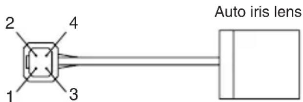
⑥ Auto iris lens connector:
Specifically used to connect the auto iris lens.
- For the video controlled type auto iris lens
Set the lens selector switch to VIDEO position.
- Connector cable leads -
- Red (power)
- Not used
- White (video)
- Black (shielded)
* Make proper isolation on the tip of the green wire to prevent a short-circuit.
- For the DC controlled type auto iris lens
Set the lens selector switch to DC position.
- Connector cable wires -
- Damping coil (-)
- Damping coil (+)
- Driving coil (+)
- Driving coil (-)

* Connect the wires as shown above.
Please refer also to the instructions of the lens to be used.
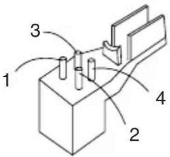
Connector pin assignment
⑦ - ⑪ Camera setup function switches
Please refer to the Operation chapter.
⑧ Focus EZ function switch
With an auto iris lens being connected, this switch is used to support the focus Adjustment. Hold down the U button longer than 2 seconds, and the lens aperture is kept open for about 1 minute. (Press it again, and the aperture opening time will be prolonged for about 30 seconds.)
To end the Focus EZ function, just press the D button.
This function helps adjust the focus easily even in broad daylight no matter how much the depth of field is.
After using this button, the unit resets itself to its original focus mode.
⑫ External input connector (GENLOCK IN)
For Gen-lock input signal.
⑬ Video output connector (VIDEO OUT)
For video signal output from camera. Connect this output to monitor or switcher, etc. This to be terminated with 75 ohms impedance at the last equipment in a loop when cascade/bridge loop connection is made
⑭ Power indicator (POWER)
The LED indicator stays on in green while the camera power is on. This camera does not have own power on/off switch. Utmost care should be paid when doing repair or service work. The maintenance indicator is built-in which makes blinking Amber and Green lights around 40,000 hours operation. It is strongly recommended to have a proper maintenance service if this maintenance indication LED blinks.
⑮ Terminal switch for GEN-LOCK
This is to terminate GEN-LOCK signal with 75 ohms impedance when the loop connection is made in Gen-lock signal feed. To terminate, make this switch ON.
⑯ Terminal switch for RS-485
In RS-485 communication link, turn this switch to ON side for one-to-one control, or turn it to OFF side for daisy-chain(loop connection).
(For use in daisy-chain connection, turn ON the terminal switch of the last device in the link.)
⑰ RS-485 input/output vs. Day/Night change-over terminal block
This block is used for RS-485 connection or for remote control of day/nigh switching.
⑱ DC12V/AC24V power input terminal
For power, apply the input power of DC10.5 - 28.0 V or AC24V ±10%.
* This installation should be made by a qualified service person and should conform to all local codes.
⑲ AC 100V power cable (In NTSC, Japanese version Only)
For AC 100V power supply.
Applicable AC should be within a range of plus/minus 10% voltage.
Note: This camera has no power switch.
Just plug in the power cable and the camera power turns ON. To make the camera power off, just unplug a power cable.
The power outlet should be handy near the camera and should be easily accessible.
5. Operation
5-1. User setup
The ICD-809 series camera has a provision of a camera setup and memory function for camera ID setting, sync system selection, various picture quality setups for optimum reproduction, back light compensation spot area setting, Privacy Mask settings, Day/Night change-over thresh-hold settings.
The SETUP MENU is displayed in a system flow chart, and the settings can be easily executed using the On-Screen-Menu system.
Alteration of these functions may be needed for some installations and we recommend that you should spend some time to become acquainted with these functions so that the best results can be obtained from this high performance TV camera.
5-2. SETUP switches and functions

The push buttons and the markings at left are provided on the rear panel of the camera.
Up Switch (U) To be used for a selection of SETUP parameters Down Switch (D) (up and down).
Right Switch (R) To be used to change the settings. Left Switch (L)
Enter Switch (E) To be used to enter or quit the setup mode and to save the setup data.
* To enter the setup mode, hold down the E button longer than 2 seconds.
5-3. Entering the setup mode and its basics
5-3-1. SETUP MENU (Main menu)
| SETUP MENU | |
| CAMERA ID | OFF |
| DAY/NIGHT | AUTO |
| SHUTTER | OFF |
| LIGHT CONT. | LENS |
| GAIN | AGC |
| WHITE BAL. | ATW1 |
| SYNC | INT |
| MENU LOCK | OFF |
| EXIT CANCEL | RESET |
Hold down the E button longer than 2 seconds, and the menu at left appears onscreen. A highlighted item is now selected.
(1) CAMERA ID Up to 24 alpha-numeric characters can be displayed on screen.
(2) DAY/NIGHT The day (color) or night (Mono) mode is selected.
(3) SHUTTER To select high speed shutter
(4) LIGHT CONTROL The backlight compensation and sensing spot area modes can be selected. The DC type iris lens is adjusted.
(5) GAIN The gain control mode is selected.
(6) WHITE BALANCE The white balance mode is selected.
The manual white balance settings are made.
(7) SYNC The Sync systems, AC line Lock, internal Lock or Gen-lock mode are selected
(8) MENU LOCK The saved settings can be locked.
(9) SETUP The EXIT, CANCEL or RESET action is selected and executed.
① EXIT: Used to save the settings and to quit the menu.
② CANCEL: Used to return the settings to the previously saved ones.
③ RESET: Used to return the settings to the factory ones.
* New settings can be saved, if EXIT is selected to quit the menu.
5-3-2. SPECIAL MENU

Highlight EXIT on the SETUP MENU screen. Hold down the L and R buttons together, and the screen at left appears on screen.
(1) PAGE PAGE (1/2, 2/2) can be selected with the "L" and "R" bunntons.
(2) CHROMA To be used to adjust the Chroma level.
(3) DETAIL To be used to adjust the details.
(4) PEDESTAL Pedestal level control
(5) VIDEO LEVEL To be used to adjust the video level.
(6) GAMMA To be used to select the gamma correction.
(7) MATRIX Selection of MATRIX Mode
(8) MONITOR Selection of Monitor types, CRT or LCD types
(9) P.MASK Privacy Mask control
(10)MIRROR To be used to select mirror-reversed images.
(11)RS-485 ID To be used to preset an ID number (1 to 207) for RS-485 link
(12)LANGUAGE To select language of menu screen (either English or French)
(13)RET/EXIT RET for returning to the main menu screen.
EXIT for saving parameters or to quit the procedure.
5-4. Setup procedures
5-4-1. CAMERA ID
(1) CAMERA ID ON/OFF setting Highlight CAMERA ID.
Using the E, L or R button, access the ON/OFF setting. Decide the ON or OFF setting with the L or R button.
| SETUP MENU | |
| CAMERA ID | OFF |
| DAY/NIGHT | AUTO |
| SHUTTER | OFF |
| LIGHT CONT. | LENS |
| GAIN | AGC |
| WHITE BAL. | ATW1 |
| SYNC | INT |
| MENU LOCK | OFF |
| EXIT CANCEL | RESET |
(2) ID characters setting
Keep CAMERA ID highlighted and press the E button.
The screen appears as shown on the right figure.
① ID Setting for Line and Starting point: For positioning the cursor, choose arrow marks, ← or → ,and push R or L button.
| ID EDIT | ||
| ABCDEFGHIJKLMNOPQRSTUVWXYZ↑ ↗→↘↓↙←↖0123456789:+-*/. · | ||
| ·········································································································································································································← →SPACE CLEARRET EXIT POS |
② Choose desired characters, or numbers, Use buttons of U, D, L, or R to do it.
③ To use E button, to display the selected characters or numbers for ID.
④ To have a space. Select SPACE and push E button. the cursor moves.
⑤ To delete all ID characters and numbers, select CLEAR and push E button.
(3) Positioning of ID Display:
ID display appears when push E button after choose POS. Move ID display to the desired place and push E button. the ID position is set and the screen goes back to normal screen.
(4) After this, decide to go back to main menu (RET), or to save data and finish this procedure (EXIT)
5-4-2. DAY/NIGHT
(1) With the L and R buttons, make the
AUTO, COLOR or B/W (Monochrome) setting.
① AUTO
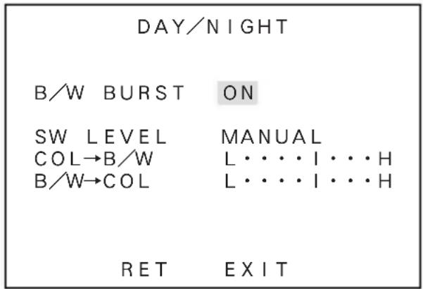
Automatic switching is made: high-quality color images during the day, and high-sensitivity monochrome pictures at night. Press the E button, and the screen at right shows up.
• B/W BURST
The burst signal in Monochrome (B/W) pictures can be selected ON or OFF.
- SW LEVEL
The brightness level for switching to the day or night mode can be preset. With L or R button, the levels can be selected in the order of BRIGHT, MID and DARK.
The following screen appears, when selected MANUAL.
The thresh-hold can be set to change from color to monochrome picture, or visa versa.
② COLOR
The color mode can be selected.
③ B/W
The Monochrome (B/W) mode can be selected. Press the E button in this mode, and the menu opens up and the “B/W BURST” setting can be made like as above ①.

④ REMOTE
The color or monochrome (B/W) mode can be remotely selected by getting the remote terminal at the back of the camera open or short-circuited. In this state, press the E button, and the sub-menu screen shows up. The terminal polarity can now be preset.
• MAKE

The monochrome (B/W) mode can be selected by getting the remote terminal short-circuited.
(The color mode can be selected with the terminal open.)
- BREAK
The monochrome (B/W) mode by getting the remote terminal open. (The color mode can be selected with the terminal short-circuited.)
5-4-3. SHUTTER
(1) This mode is effective, when the light control is LENS mode.
(2) By L or R button, high speed shutter can be valid for OFF, FL, 1/125, 1/250, 1/500, 1/1000, 1/2000, 1/4000, 1/10,000, or Variable.
(3) VARIABLE
Speed of shutter can be changed variably by L or R button. and the shutter speed can be displayed on a monitor screen. (When the setting was so made)

5-4-4 LIGHT CONTROL
(1) Select LIGHT CONTROL on the main menu using L or R button for AES or LENS set. The Iris level can be displayed only when a lens changeover switch was on DC mode.
(2) BACKLIGHT CMP.
With this mode, the back light compensation modes can be controlled by L or R button. (for ON, SPOT, or OFF).
① OFF
The backlight compensation is not active. This is the factory setting.
② SPOT
In this mode, the Spot measurement can be made by setting the desired point.
③ ON
This mode is an ordinary back light compensation.

(3) BLC LEVEL
Move the marker by L or R button. Factory setting is at the middle.
The good result can be seen by moving marker to the right side, when the difference of light amount was larger. It is recommended to control this by watching the monitor screen.
(4) WIDE BLC
If the picture turned to white and make it difficult to observe, try this to have better picture. This WIDE BLC makes compensation range larger to have moderate brightness level make a picture comfortable to eyes.
(5) IRIS LEVEL
This is displayed when using DC Iris lens. Lens Iris moves to open by sliding the marker to right. (Open means to make it brighter)
For this adjustment, it is recommended to do by watching a monitor screen.
(6) RET/EXIT/SPOT SET
① RET
Returning to the main menu.
② EXIT
To save setup parameters and to quit.
③ SPOT SET
Displaying the screen of Spot area setting, shown on the right.
1) ↑ : For the upper area control, use this arrow and push E button.
By using U or D button, decide the area and return to the light control mode by E button.

flowchart
graph TD
    A["↑"] --> B["←"]
    B --> C["RET →"]
    C --> D["↓"]
2) ↓ : To move the lower area setting mode by choosing this arrow and push E button. By U or D button, decide the area and return to the light control mode by E button.
3) ← : To select this for left side area setting mode. Using L or R button, decide the area, then return to the light control mode by E button.
4) → : This arrow is for the control of the right side area. By L or R button, decide the area, then return to the light control mode by E button.
5-4-5. GAIN
(1) By L or R button, the gain control modes can be selected.
① LOW
This fixed-gain mode keeps the sensitivity low for brighter spots.
This can be used for relatively comfortable picture reproduction with less video noise. Normally it is used with ample light condition.
② MID
This fixed-gain mode keeps the sensitivity middle between HIGH and LOW.
③ HIGH
The fixed-gain mode keeps the sensitivity high for darker scene.
④ AGC
This mode is initially set to automatically optimize the sensitivity and noise levels.
⑤ HYP-AGC
This mode is higher in sensitivity than normal AGC mode for very dark scene. Then, sometimes pictures may look rugged and maybe with conspicuous video noises, due to forced higher sensitivity to reproduce dark scene.
* In Day/Night mode with Automatic operation, only AGC and Hyper AGC are available for Gain selection.
● Round Numbers of Brightness Expression
| 100000Lux | • Sun Light in clear cloudless sky (10000Lux) |
| 10000Lux | • The sun Light after 1 hour from dawn in overcasting weather (2000Lux) • Office Desk with Fluorescent Illumination (1000Lux) |
| 1000Lux | • Sun Light 1 hour before the Sun Set (1000Lux) • Bright Pachinko Parlour or Casino (1000Lux) • Convenience Store (500Lux) • Writing Desk (400Lux) • Underground Station (300Lux) |
| 100Lux | • Twilight (100Lux) • Underground Car Parking Lot (5~30Lux) • Candle, 20 cm away (10~15Lux) |
| 10Lux | |
| 1Lux | • Evening Dusk (1Lux) |
| 0.1Lux | • Full moon night (0.1Lux) |
| 0.01Lux | • Waxing Moon (0.01Lux) |
| 0.001Lux | • Star lit evening with clear sky and without moon (0.001Lux) |
5-4-6. WHITE BALANCE
(1) By L or R button, The white balance mode can be selected.
① ATW-1 : (Factory Set Position)
Automatically, white balance is controlled.
② ATW-2 :
In this mode, the white balance control is made. But this ATW-2 mode covers wider range in the light spectral to cover the Sodium lighting.
May be not so accurate tracking as ATW-1 mode is expected, or sometimes a small difference in color reproduction from ATW-1, may occur in this ATW-2.
③ AWC :
This is ordinary one-push Automatic white balance control. Using white object and E button, white balancing is set. In this mode, setting parameters will not change by lighting variations. This mode is accurate compared with other white balance setting modes and is recommended in a stable lighting situation.
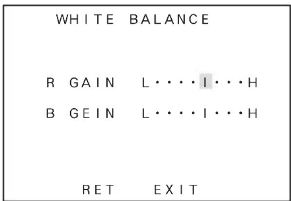
④ MANUAL :
By selecting MANUAL and push E button, the screen shown on the right will appear for the manual color control.
R GAIN is for an adjustment of Red color
B GAIN is for an adjustment of Blue color
● Colour Temperatures in Degrees Kelvin
Colour Temperature is the standard method to describe characters of light and is normally expressed in degrees kelvin (K) Large numbers show more blueish colour. (Not directly related Brightness)


5-4-7 SYNC
(1) By L or R button, INT, LL, EXT VS or EXT VBS can be selected.
(2) INT = Internal Lock
This is for internal sync lock mode, controlled by internal crystal oscillator.
(3) LL = Line Lock
This is for AC line lock mode. In this AC Line Lock mode, phase adjustment can be possible. To do it, Press E button, and the screen at right shows up for coarse and fine phase adjustment.
① COARSE
It makes possible to have 90 degree increment from 0^ , 90^ , 180^ or 270^ .
② FINE :
By L or R button, fine adjustment of the phase is possible.

(4) EXT VS
By pushing E button, the screen for adjustment will appear and the H phase adjustment can be done by L or R button.
Note that this mode can be valid when VS signal input with Gen-lock mode.

(5) EXT VBS
By pushing E button, the screen for adjustment will appear and the following parameters are becomes controllable.
① H.PHASE
The horizontal phase can be controlled by L or R button.
② SC COARSE
The sub-carrier phase can be controlled by L or R button with 90 degrees steps.

③ SC FINE
After the above SC COASE adjustment, fine tuning of sub-carrier phase can be controllable by L or R button.
5-4-8. MENU LOCK
To prevent un-intentional or intentional setup parameter change, this Menu Lock function is provided for protection. The menu lock function protects saved setting parameters against accidental or intentional alteration.
(1) To Lock
To secure the saved setting parameters to make it ON, using E button.
(2) Operation
When locked, Only EXIT is effective and all the other actions are invalid.
(3) Unlock
To un-lock, press the U, R, D, L, U, D and E buttons in this order.
If a wrong button is pressed halfway, start all over again.
5-4-9. SPECIAL MENU
(1) To go to the Special Menu, push L and R buttons together at the SET UP position.
The SPECIAL MENU screen shows up, as shown on right.
(2) CHROMA
With the L and R buttons, the chroma level can be adjusted. Make the adjustment to your desired level while watching a monitor screen.
| SPECIAL MENU V3.00 | |
| PAGE | 1/2 |
| CHROMA | L·····I···H |
| DETAIL | L·····I···H |
| PEDESTAL | L·····I···H |
| VIDEO LEVEL | L·····I···H |
| GAMMA | 0.45 |
| MATRIX | A MODE |
| MONITOR | CRT |
| RET | EXIT |
(3) DETAIL
With the L and R buttons, the detail level can be adjusted. Make the adjustment to your desired level while watching a monitor screen.
(4) PEDESTAL
By L and R buttons, the pedestal level can be adjusted. Make this adjustment to your desired level while watching a monitor screen.
(5) VIDEO LEVEL
With the L and R butons, the video level can be adjusted.
Make the adjustment to your desired level while watching a monitor screen.
(6) GAMMA
With the L and R buttons, the gamma correction can be selected (0.45/0.75/1.0).
(7) MATRIX
Can select Matrix Modes, A or B. In normal condition, the A mode is recommendable, but special cases such as under florescent lightings, or indoor situation, the B mode is possibly better for optimum picture
(8) MONITOR
By L or R button, picture reproduction mode of monitor can be selected.
① CRT is for Cathode Ray Tube (Braun Tube) type monitors.
② LCD is for FDP, Flat Display Panel type monitors, such as LCD or Plasma.
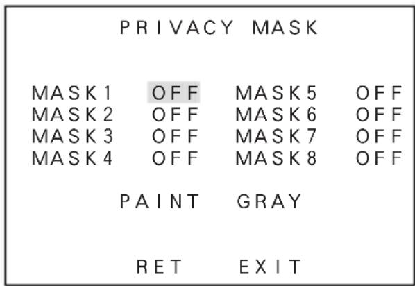
(9) P.MASK
With E button, Privacy masking (P.Mask, hereafter) control mode is available.
P.MASK can be set maximum 8 (eight) points.
① Set to make it active (valid) or not. By using U or D button, choose desired Mask number/s, and make it valid or invalid by L button for ON (valid) or R button for OFF (invalid).
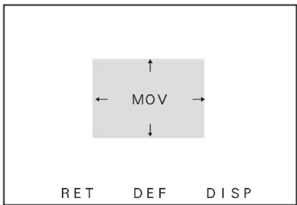
② Setting of Masking Area
The screen like the one on right appears by E button after choosing ON by L and R button.
1) Masking Area Size Change Move a cursor by Arrow mark, and use U or D button to move upper or lower change. Or use L or R button to move right or left change.
flowchart
graph TD
    A["MOV"] --> B["RET"]
    A --> C["DEF"]
    A --> D["DISP"]
2) Masking Area reposition
Move a cursor to MOV and push E button. Whole mask can be repositioned by buttons, U, D, R or L.
Push E button to set a position and return to P.MASK area set screen.
3) DEF
This is for controlling the mask size, or to initialize a position.
4) DISP
This shows the Mask which was set valid. DIPS stands for Display.
5) RET
To return to Mask Set Screen.
③ PAINT
With L or R button, desired color for P.Mask can be selected.
(Black, White or Gray)
④ RET
To return to the special menu screen.
⑤ EXIT
To save the selected parameters and to quit.
(10) MIRROR
With the L and R buttons, images can be mirror-reversed.
(11) RS-485 ID
Camera ID number can be set in 1 to 207 with R or L button.
(12) LANGUAGE
Language for the Menu screen can be selected, either English or French.
(13) RET
To return to the Main Menu.
(14) EXIT
To save the setup parameters, and to quit.
5-4-10. Communication with control device (RS-485)
The camera can be controlled from a control terminal (PC, for example), or the remote control unit provided by Ikegami, over RS-485 Link.
The RS-485 is the recommended standard by EIA for a serial data communication, one class higher than RS-422 which is for Multi-drop connection, but the 485 is the Multi-points connection type. Maxim communication speed is 10Mbps and normally extendable up to 1,200 meters (3,600ft).
When you make RS-485 connection, make it sure to connect the right terminal as there are plus and minus polarity, and also make sure to terminate at the last machine in the link of daisy chain.
For details, refer to the Communications Specifications.
Example 1: With one camera being connected

flowchart
graph LR
    A["RS-485 Termination switch ON"] --> B["PC"]
    B --> C["Monitor"]
    style A fill:#f9f,stroke:#333
    style B fill:#ccf,stroke:#333
    style C fill:#cfc,stroke:#333
Example 2: With four cameras being connected

flowchart
graph TD
    PC["PC"] -->|RS-485 Termination switch OFF| Switch1["Switch"]
    Switch1 -->|RS-485 Termination switch OFF| Switch2["Switch"]
    Switch2 -->|RS-485 Termination switch ON| Switch3["Switch"]
    Switch3 -->|RS-485 Termination switch OFF| Switch4["Switch"]
    Switch4 -->|RS-485 Termination switch OFF| Switch5["Switch"]
    Switch5 -->|RS-485 Termination switch OFF| Switch6["Switch"]
    Switch6 -->|RS-485 Termination switch OFF| Switch7["Switch"]
    Switch7 -->|RS-485 Termination switch OFF| Switch8["Switch"]
    Switch8 -->|RS-485 Termination switch OFF| Switch9["Switch"]
    Switch9 -->|RS-485 Termination switch OFF| Switch10["Switch"]
    Switch10 -->|RS-485 Termination switch OFF| Switch11["Switch"]
    Switch11 -->|RS-485 Termination switch OFF| Switch12["Switch"]
    Switch12 -->|RS-485 Termination switch OFF| Switch13["Switch"]
    Switch13 -->|RS-485 Termination switch OFF| Switch14["Switch"]
    Switch14 -->|RS-485 Termination switch OFF| Switch15["Switch"]
    Switch15 -->|RS-485 Termination switch OFF| Switch16["Switch"]
    Switch16 -->|RS-485 Termination switch OFF| Switch17["Switch"]
    Switch17 -->|RS-485 Termination switch OFF| Switch18["Switch"]
    Switch18 -->|RS-485 Termination switch OFF| Switch19["Switch"]
    Switch19 -->|RS-485 Termination switch OFF| Switch20["Switch"]
    Switch20 -->|RS-485 Termination switch OFF| Switch21["Switch"]
    Switch21 -->|RS-485 Termination switch OFF| Switch22["Switch"]
    Switch22 -->|RS-485 Termination switch OFF| Switch23["Switch"]
    Switch23 -->|RS-485 Termination switch OFF| Switch24["Switch"]
    Switch24 -->|RS-485 Termination switch OFF| Switch25["Switch"]
    Switch25 -->|RS-485 Termination switch OFF| Switch26["Switch"]
    Switch26 -->|RS-485 Termination switch OFF| Switch27["Switch"]
    Switch27 -->|RS-485 Termination switch OFF| Switch28["Switch"]
    Switch28 -->|RS-485 Termination switch OFF| Switch29["Switch"]
    Switch29 -->|RS-485 Termination switch OFF| Switch30["Switch"]
    Switch30 -->|RS-485 Termination switch OFF| Switch31["Switch"]
    Switch31 -->|RS-485 Termination switch OFF| Switch32["Switch"]
    Switch32 -->|RS-485 Termination switch OFF| Switch33["Switch"]
    Switch33 -->|RS-485 Termination switch OFF| Switch34["Switch"]
    Switch34 -->|RS-485 Termination switch OFF| Switch35["Switch"]
    Switch35 -->|RS-485 Termination switch OFF| Switch36["Switch"]
    Switch36 -->|RS-485 Termination switch OFF| Switch37["Switch"]
    Switch37 -->|RS-485 Termination switch OFF| Switch38["Switch"]
    Switch38 -->|RS-485 Termination switch OFF| Switch39["Switch"]
    Switch39 -->|RS-485 Termination switch OFF| Switch40["Switch"]
    Switch40 -->|RS-485 Termination switch OFF| Switch41["Switch"]
    Switch41 -->|RS-485 Termination switch OFF| Switch42["Switch"]
    Switch42 -->|RS-485 Termination switch OFF| Switch43["Switch"]
    Switch43 -->|RS-485 Termination switch OFF| Switch44["Switch"]
    Switch44 -->|RS-485 Termination switch OFF| Switch45["Switch"]
    Switch45 -->|RS-485 Termination switch OFF| Switch46["Switch"]
    Switch46 -->|RS-485 Termination switch OFF| Switch47["Switch"]
    Switch47 -->|RS-485 Termination switch OFF| Switch48["Switch"]
    Switch48 -->|RS-485 Termination switch OFF| Switch49["Switch"]
    Switch49 -->|RS-485 Termination switch OFF| Switch50["Switch"]
    Switch50 -->|RS-485 Termination switch OFF| Switch51["Switch"]
    Switch51 -->|RS-485 Termination switch OFF| Switch52["Switch"]
    Switch52 -->|RS-485 Termination switch OFF| Switch53["Switch"]
    Switch53 -->|RS-485 Termination switch OFF| Switch54["Switch"]
    Switch54 -->|RS-485 Termination switch OFF| Switch55["Switch"]
    Switch56["Monitor"] --> Coaxial_cable
    Coaxial_cable -.-> RS_485_control_cable
6. Warranty and after-sale service
Warranty accompanies this product. Read and fill out the warranty card that you have received at your dealer. Keep this card in a safe place.
- Please consult Ikegami Electronics (U.S.A.) Inc. or Ikegami Electronics (Europe) GmbH or your dealer for full warranty information. Your dealer will repair or replace free of charge within the warranty period according to the warranty coverage.
●For repairs after the expiration of the warranty period, consult your dealer or sales representative. It will first be judged whether the fault is repairable or not. Charged servicing will then be made upon request of the user.
●Before you ask for servicing, please ensure you read the Instruction Manual. If the unit still fails, take note of the model number, date of purchase, problem, etc. in detail, and inform your dealer or sales representative. - If you have questions about the after-sale service, contact your dealer or sales representative.
* We suggest you ask for preventive inspection as soon as possible.
7. Specifications
(1) Image Sensor: 1/3-inch High Sensitive OCML IT CCD
(2) Pixel Number: Approx. 380,000 pixels, 768(H) x 494 (V) (NTSC)
(3) Scanning system: 525 TV lines, 60 Hz, 2 : 1 interlace in NTSC
(4) Sync system: INT/LINE-LOCK (phase adjustable) (Line-
lock not usable where the power frequency and the camera's vertical frequency are different from each other or when the camera is DC-driven), Gen-lock or Crystal controlled internal lock
(5) Video output: VBS 1.0 Vp-p/75 ohms
(6) Horizontal resolution: 540 TV lines in color. 570 lines in monochrome mode. (at rated illumination)
(7) S/N ratio: More than 52d dB/rms
(with AGC OFF, Detail OFF)
(8) Minimum object illumination: In color mode;
0.15 lux at F1.2 (50 IRE, Hyper AGC On)
0.2 lux at F1.4 (50 IRE, Hyper AGC On)
In Monochrome(B/W) mode;
0.015 lux at F1.2 (25 IRE, Hyper AGC On)
0.02 lux at F1.4 (25 IRE, Hyper AGC On)
0.037 lux at F1.2 (50 IRE, Hyper AGC ON)
0.05 lux at F1.4 (50 IRE, Hyper AGC ON)
(9) AGC: ON (AGC, HYPER-AGC)/OFF (LOW, MID, HIGH) selectable
(10) AES, Auto Electronic Shutter Built-in, On or Off selectable. Control: 1 to 1600th max AES range
(11) White balance: AWC, ATW-1, ATW-2 and MANUAL Selectable
(12) Gamma correction: 0.45, 0.75 or 1.0 switchable
(13) BLC, Back Light compensation: Built-in, On or Off selectable.
Sensing Area Spot On or Off selectable.
(14) Optimum Monitor output selection: Provided for CRT or LCD types, Selectable
(15) Day/night switching: Automatic/Remote/Manual selectable (In the automatic mode, the day/night switching level can be preset. In the remote mode, the MAKE/BREAK setting can be preset.)
(16) Auto iris function: Compatible with VIDEO iris and DC iris (switchable, with DC iris level adjuster)
(17) Focus EZ function: Provided
(18) Camera ID: 1 Line
Up to 24 characters (alphanumeric and symbols)
(19) Mirror function: Image mirror-reversal function ON/OFF
(20) Local setup: Selectable and adjustable with on-screen
display using pushbuttons on the camera rear panel;
Camera ID numbering, AGC On/Off
Auto-White Balance ATW1&2,AWC,MANU selection and adjustment, Sync Selection in
AC Line Lock, Internal Crystal controlled
Lock, LL phase adjustment, iris level, spot area setting, optimum monitor selection for
CRT or LCD types, Detail correction
management, Chroma level control, Day/
Night mode switching and Thresh-hold
(21) Remote setup: Provided (Control by RCU-701/RCU-801 or RS-485)
Same control parameters as with the local setup on the rear panel
(22) Lens mount: CS mount
(23) Lens Flange Back Adjustment: Provided. Screw Lock type with rotary Disk
(24) Power Requirement: ① AC 24 V ±10%, 60 Hz,
or DC 12 V (+10.5V to +28 V)
② AC 100V, (Japanese version only)
(25) Power consumption/current: 4.3 watts nominal, 350mA, for AC 24 V;
4.2 watts nominal, 340mA, for DC 12 V
3.7 watts nominal, 70mA, for Japanese
100V version
(26) Operating temperature -10^ to +50^ ,
and relative humidity: +30 to +90% RH (No Condensation)
(27) Camera mount: 1/4" - 20UNC (top and bottom mountable)
(28) Outer dimensions: 62(W) x 55(H) x 122(D) mm
(no protrusion included)
(29) Weight: 420g, AC 24 V and DC12 V version
(30) Input/output connectors: • VIDEO OUT; BNC
- GENLOCK IN; BNC
- LENS; 4P (E4-191J-150 type)
- DC 12V/AC 24V input; 2-pin terminal block
- RS-485 input/output vs. Day/Night change-over input; 5P push-in terminal
(31) Accessories: Instruction Manual, 1 copy
* Specifications and design are subject to change for product improvements without notice.
natural_image
Symbol of a trash bin with crossed lines indicating no waste or restriction, and a solid black rectangle below (no text or labels)| ID EDIT | ||
| ABCDEFGHIJKLMNOPQRSTUVWXYZ↑ ↗→↘↓↙←↖0123456789:+-*/. · | ||
| ········································································································································································································· | ||
| ← → | ||
| SPACE | CLEAR | |
| RET | EXIT | POS |
(6) RET/EXIT/SPOT SET
① RET
flowchart
graph TD
    A["MOV"] --> B["RET"]
    A --> C["DEF"]
    A --> D["DISP"]
8. External Appearance
(AC24V/DC12V type)
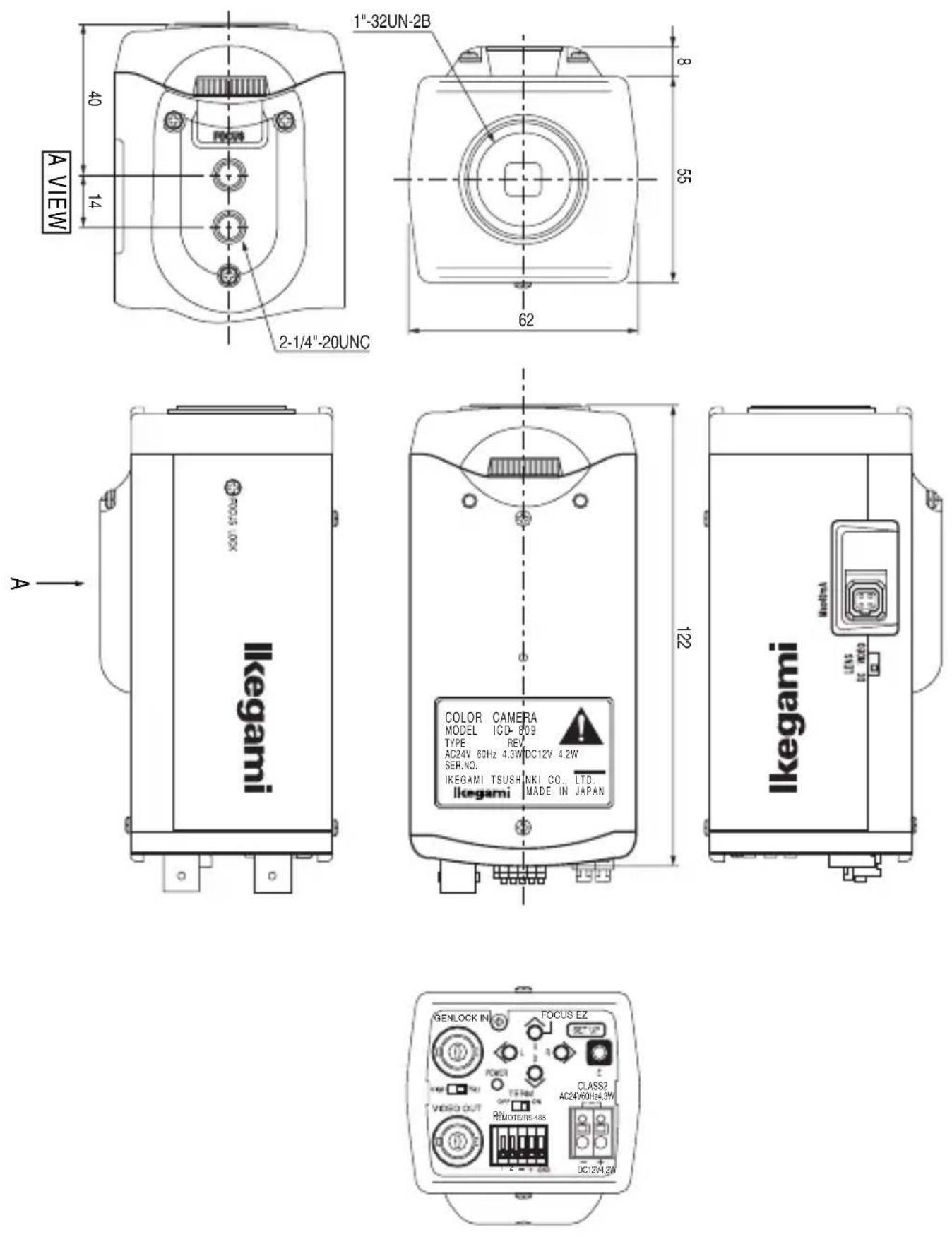
(AC100V type)

9. Setup Menu

flowchart
graph TD
    A["CAMERA ID OFF"] --> B["ON"]
    B --> C["ALPHANUMERIC POSITION"]
    C --> D["RET"]
    D --> E["EXIT"]
    E --> F["BRIGHT MID DARK MANUAL"]
    F --> G["COL → B/W *ADJUST B/W → COL *ADJUST"]
    G --> H["EXIT"]
    H --> I["L U D R"]

    J["DAY/NIGHT AUTO ON"] --> K["REMOTE"]
    K --> L["COLOR"]
    L --> M["B/W"]
    M --> N["CONTROL SIGNAL"]
    N --> O["MAKE BREAK"]
    O --> P["B/W BURST ON B/W BURST OFF"]

    Q["SHUTTER OFF"] --> R["1/100 1/125 1/250 1/500 1/1000 1/2000 1/4000 1/10000 VARIABLE"]
    R --> S["1/1000 1/125 1/250 1/500 1/1000 1/2000 1/4000 1/10000 VARIABLE"]
    S --> T["1/1000 1/125 1/250 1/500 1/1000 1/2000 1/4000 1/10000 VARIABLE"]
    T --> U["1/1000 1/125 1/250 1/500 1/1000 1/2000 1/4000 1/10000 VARIABLE"]
    U --> V["1/1000 1/125 1/250 1/500 1/1000 1/2000 1/4000 1/10000 VARIABLE"]
    V --> W["AES"]
    W --> X["NOT available by connecting Auto iris lens."]
    X --> Y["SPOT"]
    Y --> Z["IRIS LEVEL BLC LEVEL WIDE BLC ON IRIS LEVEL RET"]
    Z --> AA["SPOT SET"]
    AA --> AB[ADJUST AREA *ADJUST AREA *ADJUST AREA *ADJUST AREA *ADJUST AREA *ADJUST AREA *ADJUST AREA *ADJUST AREA *ADJUST AREA *ADJUST AREA *ADJUST AREA *ADJUST AREA *ADJUST AREA *ADJUST AREA *ADJUST AREA *ADJUST AREA *ADJUST AREA *ADJUST AREA *ADJUST AREA *ADJUST AREA *ADJUST AREA *ADJUST AREA *ADJUST AREA *ADJUST AREA *ADJUST AREA *ADJUST AREA*ADJUST AREA *ADJUST AREA *ADJUST AREA *ADJUST AREA *ADJUST AREA *ADJUST AREA *ADJUST AREA *ADJUST AREA *ADJUST AREA *ADJUST AREA *ADJUST AREA *ADJUST AREA *ADJUST AREA *ADJUST AREA *ADJUST AREA *ADJUST AREA *ADJUST AREA *ADJUST AREA *ADJUST AREA *ADJUST AREA *ADJUST AREA *ADJUST AREA *ADJUST AREA *ADJUST AREA *ADJUST AREA **ADJUST AREA***
    style A fill:#f9f,stroke:#333
    style J fill:#f9f,stroke:#333
    style Q fill:#f9f,stroke:#333
    style R fill:#f9f,stroke:#333
    style S fill:#f9f,stroke:#333
    style T fill:#f9f,stroke:#333
    style U fill:#f9f,stroke:#333
    style V fill:#f9f,stroke:#333
    style W fill:#f9f,stroke:#333
    style X fill:#f9f,stroke:#333
    style Y fill:#f9f,stroke:#333
    style Z fill:#f9f,stroke:#333
    style AA fill:#f9f,stroke:#333
    style AB fill:#f9f,stroke:#333
    style AC fill:#f9f,stroke:#333
    style AD fill:#f9f,stroke:#333
    style AE fill:#f9f,stroke:#333
    style AF fill:#f9f,stroke:#333
    style AG fill:#f9f,stroke:#333
    style AH fill:#f9f,stroke:#333
    style AI fill:#f9f,stroke:#333
    style AJ fill:#f9f,stroke:#333
    style AK fill:#f9f,stroke:#333
    style AL fill:#f9f,stroke:#333
    style AM fill:#f9f,stroke:#333
    style AN fill:#f9f,stroke:#333
    style AO fill:#f9f,stroke:#333

flowchart
graph TD
    A["WHITE BALANCE ATW1"] --> B["ATW2"]
    B --> C["AWC PUSH"]
    C --> D["MANUAL"]
    D --> E["Tracking"]
    E --> F["R GAIN"]
    F --> G["B GAIN"]
    G --> H["*ADJUST"]
    H --> I["RET"]
    I --> J["E"]
    J --> K["EXIT"]
    L["SYNC INT"] --> M["LL"]
    M --> N["Auto-Detection Sync Signal"]
    N --> O["EXT VBS"]
    O --> P["EXT VS"]
    P --> Q["+E"]
    Q --> R["+U RDLUDE"]
    R --> S["+E"]
    S --> T["SYNC VBS *ADJUST"]
    T --> U["SYNC VS *ADJUST"]
    U --> V["RET"]
    V --> W["E"]
    W --> X["EXIT"]
    Y["MENU LOCK OFF ON"] --> Z["RESET"]
    Z --> AA["SPECIAL MENU"]
    AA --> AB["PUSH L AND R AT ONCE"]
    AB --> AC["SPECIAL MENU"]
    AC --> AD["CHROMA"]
    AD --> AE["DETAIL"]
    AE --> AF["PEDESTAL"]
    AF --> AG["MATRIX"]
    AG --> AH["A MODE"]
    AH --> AI["B MODE"]
    AJ["VIDEO LEVEL"] --> AK["GAMMA"]
    AK --> AL["0.45"]
    AL --> AM["0.75"]
    AM --> AN["1"]
    AO["MONITOR"] --> AP["CRT"]
    AP --> AQ["LCD"]
    AQ --> AR["P. MASK SET"]
    AR --> AS["ON"]
    AS --> AT["OFF"]
    AT --> AU["+E"]
    AU --> AV["Mirror"]
    AV --> AW["OFF"]
    AW --> AX["ON"]
    AX --> AY["001~207"]
    AY --> AZ["RS-485 ID"]
    AZ --> BA["LANGUAGE"]
    BA --> BB["ENGLISH FRANCAIS"]
    BB --> BC["RET"]
    BC --> BD["E"]
    BD --> BE["EXIT"]

    subgraph TOP 3RD2ND
        direction TB
        L
        M
        N
        O
        P
        Q
        R
        S
        T
        U
        V
        W
        X
        Y
        Z
        AA
        AB
        AC
        AD
        AE
        AF
        AG
        AH
        AI
        AJ
        AK
        AL
        AM
        AN
        AO
        AP
        AQ
        AR
        AS
        AT
        AU
        AV
        AW
        AX
        AZ
        BA
        BB
        BC
        BD
        BE
        BE
        BE
        BE
        BE
        BE
        BE
        BE
        BE
        BE
        BE
        BE
        BE
        BE
        BE
        BE
        BE
        BE
        BE
        BE
        BE
        BE
        BE
        BE
        BE
        BE
        BE
        BE
        BE
        BE
        BE
        BE
        BE
        BE

    subgraph Area POSITION
        direction TB
        AN
        AO
        AP
        AQ
        AR
        AS
        AT
        AU
        AV
        AW
        AX
        AZ
        AO
        AP
        AR
        AS
        AT
        AU
        AV
        AW
        AX
        AZ
        AO
        AP
        AR
        AS
        AT
        AU
        AV
        AW
        AX
        AZ
        AO
        AP
        AR
        AS
        AT
        AU
        AV
        AW
        AX
        AZ
        AO
        AP
        AR
        AS
        AT,
      Area Position default set Mask display

    %% Diagrammatic elements; labels on diagram elements; values are estimated as follows: e.g., 'BEFORE SETTING DEFAULT'; text labels 'PUSH L AND R AT ONCE' and 'SETTING'
Ikegami
■ Ikegami Electronics (U.S.A.), Inc.
37 Brook Avenue, Maywood, N.J. 07607, U.S.A.
Phone: (201) 368-9171, FAX (201) 569-1626
www.lkegami.com
or
■ Ikegami Electronics (U.S.A.), Inc, West Coast Office
2631 Manhattan Beach Blvd., Redondo Beach, C.A. 90278
Phone: (310) 297-1900, FAX (310) 536-9550
www.lkegami.com
■ Ikegami Electronics (Europe) GmbH
Ikegami Strasse 1, D-41460 Neuss, Germany
Phone : 02131-123-0, FAX 02131-102820
www.lkegami.de
■ Ikegami Electronics U.K. Office:
Unit E1, Cologne Court, Brooklands Close,
Windmill Road, Sunbury-on-Thames,
Middlesex, TW16 7EB, U.K.
Phone:01932-769700 FAX 01-92-769710
www.lkegami.co.uk

- Ikegami
- Contents
- NOTE:
- CAUTION;
- Instructions for Disposal of Electric and Electronic Equipment in Private Household
- Disposal of used Electric and Electronic Equipment
- (Applicable in the European Union and other European countries with separate collection systems)
- Handling precautions
- General
- Features
- Names of parts and their functions
- ① Lens mount (CS mount)
- ② Lens flange back focus adjuster
- ③ Back focus lock screw
- ④ Camera mounting screw holes
- ⑤ Lens iris control selector switch
- ⑥ Auto iris lens connector:
- - For the video controlled type auto iris lens
- - For the DC controlled type auto iris lens
- ⑭ Power indicator (POWER)
- ⑮ Terminal switch for GEN-LOCK
- ⑯ Terminal switch for RS-485
- ⑰ RS-485 input/output vs. Day/Night change-over terminal block
- ⑱ DC12V/AC24V power input terminal
- ⑲ AC 100V power cable (In NTSC, Japanese version Only)
- Note: This camera has no power switch.
- Operation
- 5-1. User setup
- 5-2. SETUP switches and functions
- 5-3. Entering the setup mode and its basics
- 5-3-1. SETUP MENU (Main menu)
- 5-3-2. SPECIAL MENU
- 5-4. Setup procedures
- 5-4-1. CAMERA ID
- 5-4-2. DAY/NIGHT
- ④ REMOTE
- • MAKE
- - BREAK
- 5-4-3. SHUTTER
- VARIABLE
- 5-4-4 LIGHT CONTROL
- ③ SPOT SET
- 5-4-5. GAIN
- 5-4-6. WHITE BALANCE
- ● Colour Temperatures in Degrees Kelvin
- 5-4-7 SYNC
- 5-4-8. MENU LOCK
- 5-4-9. SPECIAL MENU
- MATRIX
- MONITOR
- P.MASK
- 5-4-10. Communication with control device (RS-485)
- Warranty and after-sale service
- Specifications
- RET/EXIT/SPOT SET
- External Appearance
- Setup Menu
Brand : Ikegami
Model : ICD-809
Category : Surveillance Camera