PAC-508 - Surveillance Camera Ikegami - Free user manual and instructions
Find the device manual for free PAC-508 Ikegami in PDF.


| Product Type | Surveillance Camera |
| Brand | Ikegami |
| Model | PAC-508 |
| Dimensions (approx.) | 200 x 150 x 100 mm |
| Weight (approx.) | 1.5 kg |
| Power Supply | 12V DC, 1A |
| Video Resolution | 1080p Full HD |
| Lens Type | Varifocal, 2.8-12mm |
| Night Vision | IR LEDs, up to 30m |
| Weatherproof Rating | IP66 |
| Mounting Type | Ceiling or wall mount |
| Connectivity | BNC (video), RJ45 (optional) |
| Main Functions | Motion detection, remote viewing, recording |
| Maintenance and Cleaning | Clean lens with soft cloth; avoid harsh chemicals |
| Safety Precautions | Use only supplied power adapter; keep away from water |
| Spare Parts and Repairability | Contact authorized service center; no user-serviceable parts |
| General Information | Designed for indoor/outdoor surveillance |
Frequently Asked Questions - PAC-508 Ikegami
User questions about PAC-508 Ikegami
0 question about this device. Answer the ones you know or ask your own.
Ask a new question about this device
Download the instructions for your Surveillance Camera in PDF format for free! Find your manual PAC-508 - Ikegami and take your electronic device back in hand. On this page are published all the documents necessary for the use of your device. PAC-508 by Ikegami.
USER MANUAL PAC-508 Ikegami
natural_image
Technical line drawing of a mechanical component with mounting holes and a central shaft (no text or symbols)CYLINDRICAL HOUSING PACKAGES

natural_image
Technical line drawing of a mechanical component with mounting holes and a cylindrical housing (no text or symbols)
natural_image
Technical line drawing of a mechanical device with no visible text or symbols
natural_image
Technical line drawing of a mechanical component with no visible text or symbolsPAC-508 SERIES
PAC-509SERIES

natural_image
Technical line drawing of a mechanical assembly with no visible text or symbolsINSTALLATION AND OPERATING INSTRUCTIONS
WWW.IKEGAMI.COM
IMPORTANTSAFEGUARDS
I. Read Instructions-All the safety and operating instructions should be read before the unit is operated.
-
Retain Instructions- Thesafety and operating instructions should be retained for further reference.
-
HeedWarnings-Allwarningsontheunitandinthe operatinginstructionsshouldbeadheredto.
-
FollowInstructions-Alloperatinganduseinstructions shouldbefollowed.
-
Cleaning-Unplugtheunitfromtheoutletbefore cleaning.Donotuseliquidcleanersoraerosolcleaners.Useadampclothforcleaning.
-
Attachments-Donotuseattachmentsnotrecommended by the product manufacturer asthe may cause hazards.
-
Accessories-Donotplacethisunitonanunstablestand, tripod,bracket,ormount. Theunitmayfall,causing seriousinjurytoapersonandseriousdamagetotheunit. Useonlywithastand,tripod,bracket,ormount recommendedbythemanufacturerorsoldwiththe product.Anymountingoftheunitshouldfollowthe manufacturer'sinstructionsandshoulduseamounting accessoryrecommendedbythemanufacturer.

Anapplianceandcartcombinationsshouldbemoved withcare.Quickstops,excessiveforce,anduneven surfacesmaycausetheapplianceandcart combinationtooverturn.
-
Ventilation-Openingsintheenclosure, ifany, are provided for ventilation, to ensurer reliable operation of the unit, and top protect it from overheating. These openings must not be blocked or covered. This unit should not be placed in a built-in installation unless proper ventilation is provided orthemanufacturer's instructions have been adhered to.
-
PowerSources-Thisunitshouldbeoperatedonlyfrom thetypeofpowersourceindicatedonthemarkinglabel. If you are not sure of the type of powersupply you plan to use, consult your appliance dealer or local power company. For units intended to operate from battery power or other sources, referto the operating instructions.
-
Groundingor Polarization-Thisunitmaybe equipped with apolarized alternating-currentlineplug(aplughaving onebladewiderthantheother). Thisplugwillfitinto the poweroutletonlyoneway. Thisisasafetyfeature.Ifyou are unabletoinserttheplugfullyinto the outlet, try reversing the plug. If the plug should still fail to fit, contact yourelectriciantoreplace your obsolete outlet. Donot defeat the safetypurpose of the polarized plug. Alternatively, thisunitmaybe equipped with a 3-wire grounding-type plug, aplughavingathird (grounding) pin. This plug will only fit into a grounding-type power outlet. This is as safety feature. If you are unable to insert the plug into the outlet, contact yourelectriciantoreplace your obsolete outlet. Donot defeat the safetypurpose of the grounding-type plug.
-
PowerCordProtection-Powersupplycordsshouldbe routedsothattheyarenotlikelytobewalkedonor pinchedbyitemsplaceduponoragainstthem, paying particularattentiontocordsandplugs, convenience receptacles,andthepointwheretheyexitfromthe appliance.
-
PowerLines-Anoutdoorsystem should not belocated in the vicinity of overhead power lines or other electric light or power circuits or where it can fall into such power lines or circuits. When installing an outdoor system, extreme careshould betakentokeep from touchings such power lines or circuits as contact with them might be fatal. U.S.A. modelsonly-referto the National Electrical Code Article 820 regarding installation of CATV systems.
-
Overloading-Donotoverloadoutletsandextension cordsasthiscanresultinafireorelectricshock.
-
ObjectandLiquidEntry-Neverpushobjectsofanykind intothisunitthroughopenings, astheymaytouch dangerousvoltagepointssorshortoutpartsthatcould resultinafireorelectricshock. Neverspillliquidofany kindontheunit.
-
Servicing-Donotattempttoservicethisunityyourselfas openingorremovingcoversmayexposeyouto dangerousvoltageorotherhazards.Referallservicingto qualifiedservicepersonnel.
-
Damage Requiring Service-Unplug the unit from the outlet and refers servicing to qualified service personnel under the following conditions:
a. Whenthepowersupplycordorplugisdamaged.
b. If liquid has been spilled or object have fallen into the unit.
c. If the unithas been exposed to rain or water.
d. If the unit does not operate normally by following the operating instructions. Adjust only those control that are covered by the operating instructions, as an improper adjustment of other control may result in damage and will often require extensive work by a qualified technician to restore the unit to its normal operation.
e. If the unithas beendropped or the cabinethas been damaged.
f.Whentheunitexhibitsadistinctchangein performance--thisindicatesaneedforservice.
-
ReplacementParts-Whenreplacementpartsare required, besuretheservicetechnicianhasused replacementpartsspecifiedbythemanufacturerorhave thesamecharacteristicsastheoriginalpart.Unauthorized substitutionsmayresultinfire,electricshock,orother hazards.
-
SafetyCheck-Uponcompletionofanyserviceorrepairs tothisunit, ask the servicetechnician to perform safety checkstodeterminethattheunitisinproperoperating condition.
-
CoaxGrounding-Ifanoutsidecablesystemisconnected totheunit, besurethecablesystemisgrounded. U.S.A. modelsonly--Section810oftheNationalElectricalCode, ANSI/NFPANo.70-1981, providesinformationwith respecttopropergroundingofthemountandsupporting structure, groundingofthecoaxtoadischargeunit, size ofgroundingconductors, locationofdischargeunit, connectiontogroundingelectrodes, andrequirementsfor thegroundingelectrode.
-
Lightning-Foradded protection of this unit during a lightningstorm, or when it is left unattended and unused for long period so time, un plugit from the wall outlet and disconnect the cables system. This will prevent damage to the unit duet lighting and power line surges.
SAFETY PRECAUTIONS

CAUTION
RISK OF ELECTRIC SHOCK. DO NOT OPEN!
CAUTION: TOREDUCETHERISKOFELECTRICAL SHOCK, DONOTOPENCOVERS. NOUSERSERVICE-ABLEPARTSAREINSIDE. REFERSERVICING TO QUALIFIED SERVICE PERSONNEL.
Thislabelmayappearonthebottomoftheunitduetospace limitations.

Thelightningflashwithanarrowheadsymbol withinanequilateraltriangleisintendedtoalert theusertothepresenceofuninsulated "dangerousvoltage"withintheproduct's enclosurethatmaybeofsufficientmagnitudeto constituteariskofelectricshocktopersons.

The exclamationpoint within an equilateral triangle is intended to alert the userto presence of important operating and maintenance (servicing) instructions in the literature accompanying the appliance.
SECURITE

ATTENTION
RISQUE DÍ OCUTION. NE PAS OUVRIR

1 U N P A C K I N G 5.1ModelDesignation
Unpackcarefully. This is a mechanicalequipment and should be handled with care.
Checkforthefollowing:
•Housing(withcorrectmodelnumber).
•HousingMount(withcorrectmodelnumber).
- HardwareKit:
4#10-24x1/2-inButtonHeadScrews
IMSWashers
11/8-inAllenwrench
Ifanitemappearstohavebeendamagedinshipment,replace itproperlyinitscartonandnotifytheshipper.Ifanyitems aremissing,notifylkegami.
Theshippingcartonisthesafestcontainerinwhichtheunit maybetransported.Saveitforpossiblefutureuse.
2ACCESSORIES
2.1 Sunshields
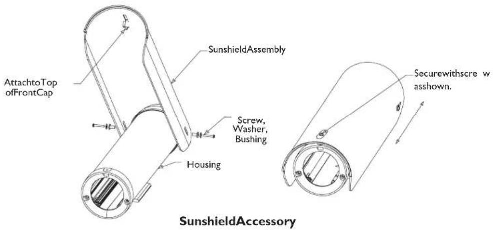
Provide protection from the direct tray so sun and promote cooling to reduce internal housing temperatures. Strongly recommended for housing to be used outdoors.
IK-HS9480SS:For I "Lhousing.
IK-HS9483SS:For16"Lhousing.
3SERVICE
If the uniteverneedsrepairserviceorparts, the customer should contact likegami.
4CAREANDMAINTENANCE
Regularly scheduled maintenance will help prolong the operation life of this unit. Clean the viewing window was needed with a mild, non-abrasive detergent in water and a soft cloth.
5INSTALLATION
This installations should be made by qualified service personnel and conform to the National Electrical Code and applicable local codes.
| Part Number | Description | Voltage/Power V/W |
| PAC-508OD | Indoor/OutdoorHousingPackage; 520TVLColorCamera(ICD-508);2.8-12mmDCAuto-Iris Lens;FeedthruWallMount | 24/4 |
| PAC-508OD2 | Indoor/OutdoorHousingPackage; 520TVLColorCamera(ICD-508);5-50mmDCAuto-Iris Lens;FeedthruWallMount | 24/4 |
| PAC-509OD | Indoor/OutdoorHousingPackage; 540TVLColorCamera(ICD-509);2.8-12mmDCAuto-Iris Lens;FeedthruWallMount | 24/4 |
| PAC-509OD2 | Indoor/OutdoorHousingPackage; 540TVLColorCamera(ICD-509);7.5-50mmDCAuto-Iris Lens;FeedthruWallMount | 24/4 |
| PAC-509ODH | Indoor/OutdoorHousingPackage w/heater&blower 1;540TVL ColorCamera(ICD-509);2.8-12mmDCAuto-IrisLens;Feed thruWallMount | 24/27 |
| PAC-509OD2H | Indoor/OutdoorHousingPackage w/heater&blower 1;540TVL ColorCamera(ICD-509);7.5-50mmDCAuto-IrisLens;Feed thruWallMount | 24/27 |
| I.Theheatersandblowersforallmodelsoperateat50/60Hz. | ||
DoNotExceed30VACInputon24VACmodels. Operationabove30VACviolateslowvoltage operation(Class2Specifications).Normaloperationis 24VAC.
TUVApproved24VACModels
Caution: Useanapprovedpowersupply incorporating reinforcedinsulationfromprimarytosecondaryto isolateunitfrommains.
5.3 ToolsRequired
-Smallflatbladescrewdriver.
-Phillipsscrewdriver(P2).
-Adjustablewrench.
-Wirecutter/stripper/crimpertool.
-5/32-in(or4mm)hexwrench.
5.4 Cable Requirements
VideoTransmission(Coaxial)
CableType:RG-59/Uforruns<300m(1000ft). RG-11/Uforruns<600m(2000ft).
CableSize: Outsidediameterbetween 4.6mm(0.181-in)-7.9mm(0.312-in).
CableShape:Round. Shield:> _ 93%Braidedcoppershield.
CenterConductor:Strandedcoppercenter.
DCResistance:< _15Ohms/1000(RG-59/U). ≤ 6Ohms/1000(RG-11/U).
CableImpedence:75Ohm.
AgencyRating:UL. Environmental:Outdoorrated.
TemperatureRating: ≥ 80°C.
Sources:Belden9259. Belden9238.
InputPowerCord-NorthAmerican
CableType:SJTOW-Arated. CableSize:Outsidediameterbetween 4.3mm(0.170in)-11.9mm(0.470in).
CableShape:Round. Conductors:3conductorversionand 2conductorversion.
AgencyRating:UL/C.S.A.,ULVW-I.
Environmental: Outdoorrated.
TemperatureRating: 105°C.
VoltageRating:300V. Sources:Belden19506. Belden19509. Northwire573939.
InputPowerCord-European
CableType:H05RN-F3G0.75and H05RN-F3G1.00. CableSize:Outsidediameterbetween 4.3mm(0.170in)-11.9mm(0.470in).
CableShape:Round. Conductors:3conductorversion and 2conductorversion.
AgencyRating:VDE. Environmental:Outdoorrated.
Sources: Olflex | 600252. Olflex | 600253.
LensControlCable
CableType: Jacketed multiconductor cable. CableSize: Outsided diameter between 4.3mm(0.170in)–11.9mm(0.470in).
CableShape:Round. Shield:Overallshielding. Conductors:Stranded20to16AWGwire.
No.ofConductors: 4and8.
Conductor Insulation: Colorcoded. Sources:Belden9552. Belden9554.
5.5 HousingMountDescription
Feed-throughMount.
Themountisanindoor/outdoormountdesignedforcamera housinginstallationsupto9kg(20lb)ratedload.Madeof lightweightaluminumandfeaturingweldedconstructionthe feed-throughmountprovidesanextremelyrigidcamera mountingsurface.
5.6 Attaching the Housing to the Mount
-
Usethetwo1/4-20x1/2-inchscrewsandtwo1/4-inch springwashersprovidedinthehardwarekittomount thehousingtoamountorapan/tilt. Thespringwashers mustbeusedforthescrewstothreadproperly.
-
Theoutermostsetof1/4-20threadedholesinthebase of thehousingareformountingtofeed-throughmounts and theinnermost1/4-20holesareformountingtoall othermountsandpan/tilts.
5.7 InstallationoftheMount
I. Determineasecurewallmountinglocation. WARNING: Donotmountinaninverted position.
- ⚠️ Cautions:
a. Forasecureinstallation,usefour8-mm(5/16-in) diameterfasteners(notincluded). Usestainlesssteel orzincplatedfasteners.
b. Ifboltsareused,theyshouldextendthroughthe mountingsurfaceandbesecuredwithflatwashers, lockwashers,andnutsontheoppositeside.Each boltmusthaveaminimumpull-outstrengthof200 kg(450lb).
c. Ifstudsareused,theyshouldbeanchoredin concreteorweldedtoasteelbackerplate.Each studmusthaveaminimumpulloutstrengthof200 kg(450lb).
d. Ifthewallmountisattachedtowoodortoablind structure(withnoaccesstotherear),eachfastener musthaveaminimumpull-outstrengthofatleast 200kg(450lb).
WARNING: Allmountsaredesigned to supportaloadonlyinaverticaldirection. MountsMUSTbepositionedasshownunder SPECIFICATIONS.
- Locatethefourholesorstudlocationsusingtheflangeas atemplate(fourholesequallyspacedona69.9-mm(2-3/4-inboltcircle).
- Feedwiresthroughthelargeholeintheflangeorthrough theslotonthesurfacewherethecamerahousingmounts.
-
Installthemountusingboltsorstudsatleast8-mm(5/16-in)indiameter.
-
Tomountthecameraorcamerahousing:
a. Mountcamerawithatwo1/4-20boltsandlock washers(notfurnished)inthe2holesofthe adjustablehead.Feedwiresthroughthecenterhole andoutthroughtheholenearthebase.
b.Mounthousingwithtwo 1/4-20boltsand lockwashers(notfurnished).Feedwiresthrough centerholeandoutthroughtheholenearthebase.
c. Lockmountheadinpositionbyusingthesupplied 1/8-inchlong-armhexwrenchtotightenscrews.
5.8 CoverRemoval
I. Loosenthetwoscrewsontherearofthehousing. Thesescrewsarecaptiveandwillnotcomeoutallthe way.DoNotremovethebottomtwoscrews.See Figure I.

Figure1:LooseningCaptiveScrews
- Graspthehousing'sfrontcapandpullforward. Donot squeeze thecoveritself. This will make it difficult to slide off the cover. See Figure 2.
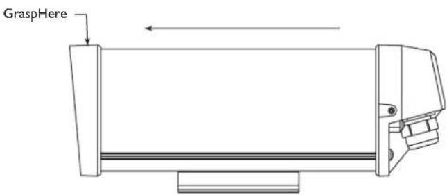
Figure2:RemovingtheCover
- Thecoverisattachedtothebase.Allowthecoverto danglefromthebase.
5.9Camera/LensInstallation
I. Loosenthetwoscrewsholdingthecamerabracketto thebase.Itisnotnecessarytoremovethemcompletely. SeeFigure3.

Figure3:RemovingtheCameraBracket
- Removethecamerabracketfromthebase.Ifyouareusing thefeed-throughfeature,refertoSection5.9.4atthis time.
5.9.1 MountingfixedlenscamerasinHousings
3a. Attachthelenstothecamera.
3b. Usethe1/4-20x3/8-inchscrewtomountthecamerato thecamerabracket. Thelensshouldextendapproximately 6mm(0.25-inch) from the front of the camerabracket. See Figure4.

Figure4: Attaching the Camera
5.9.2 Camera/LensWiring
Thehousingshipsfromthefactorywiththecameraandlens pre-wired. Refertotheirrespectiveinstallationmanualsfor additionalinformation.
5.9.3 Conduit
Thesehousingsaredesignedtoallowconduittobedirectly connected.
- Removetherearfittingsandattachtheconduitand conduitfittingsdirectlytothehousingrearcap. The holesaccept 1/2-inchconduitfittingsandPG13.5conduit fittings.Anyunusedholescanbecoveredusingtheplugs providedinthehardwarekit.
5.9.4 Feed-through Wiring
Thesehousingshavethecapabilityofhavingthecablingfeed throughthefootofthehousing. Thisrequirestheuseof feed-throughmounts.
- Prior to mounting the camera, removethetwodome plugs located inside the housing. See Figure 5.
- Screwthetwo3/8-inchNPTfittingsintothefootofthe housing.
- Pull the cabling through the fittings and into the housing. Tightenthefitting to 4.0N -m to 4.5 N·m (35 in-lbto 40in ·lb). Thisor quering is approximately l to l-1/2 turn spast the point where the fitting start stogri p the wire. Failuretodosowill result in water damageto all electronic parts
- Attachthefoottothetopbracketofthemount.
- Cover the holes in there are a cap with a rubber plug provided. Pushin until flush and then release.

Figure5:Feed-throughWiring
5.9.5 Power Connections
Powerconnectionintothehousingsistobesuppliedthrough a minimumtypeULStandard"SJ"cordacceptablefor outdooruse.InstallationmustconformtoacceptableNEC andlocalcodes.For24voltcameras,usethechartbelowfor selectingtheproperwiresize.
RecommendedMaximumCableLengthsforHousings Equippedwith24VoltCameras,Heaters,and Blowers
WireSizeHousingDistance mm ^2 AWGmetersfeet
0.52041.1135
11867.0220
1.516106.7350
2.514170.7560
412274.3900
610438.91440
108 685.82250
NOTE: The use of wire sizes larger than 1.5 mm ^2 (16 AWG) will require a splice in order to accommodate the terminal block. The above figures are based on a 24VAC and a 21.6 VAC minimum voltage to the device.
- Installoneofthelarge 1/2-inchNPTfittingsintooneof theholesintherearcap. Theterminalblockside is preferable. If you are using the feed-throughoption, ignore this step.
- Routethepowercablethroughthefittingintherearcap oroneofthefeed-throughfittingsinthefoot.
- There are twodifferent terminal blocks provided. While some accept wireranging from 22 to 14 AW Gor 1.5 mm ^2 others accept wirer ranging from 18 to 12 AW Gor 2.5mm ^2 . When using larger wiresizes, splicetoasmaller sizewire at the terminal block end. Thesplicemayneed to be enclosed in junction box if it does not pass through the fittings.
- Ascrew/terminallugisprovidedforsecuringasafety ground. To attachthesafetygroundingwire(green115 volt, green/yellow230volt), firstunscrewtheterminal lugandstripandcrimpthegroundingwireintothelug. AttachtheterminallugtothebracketusingtheM4x10 screwprovided(11"LhousingmodelsuseanM4Nut toscrewthelugtothebase). SeeFigure6.

Figure6: PowerConnections-NonfanUnits

Figure7: PowerConnections-FanUnits
- Pullanyexcesswireoutofthehousingandtightenthe fittingto8.5N .m to 9 .0 N (7 5 ilbto80in .lb). This torqueratingisapproximately1 to1-1/2turnspastthe pointwherethefittingstartstogripthewire.Failureretodosowillallowwatertoenteranddamageallelectronic parts.

Besuretosecurelytightenallfittingstoensure aliquid-tightseal.Failureretodosocouldallow watertoenterthehousinganddamagethe cameraandlens.
- Connect the supply power wire to the left side or the tops of the terminal block provided. Strip no less than 6 mm (0.25-inch) and more than 8 mm (0.31-inch) of insulation away from the wire. Besure not to nick the wires. See Figure 7.
- Cutthecamerapowercord, leavingenoughcableto allowconnectiontotheterminalblock.Stripnolessthan 6mm(0.25-inch)andnomorethan8mm(0.31-inch)of insulationawayfromthewire.Besurenottonickthe wires.Connectthesewirestotheleftsideorthetop sideoftheterminalblock.
- Onheaterandheater/blowerunits, makesuretheheater and fanwiresstayconnectedtotheterminalblock.
5.10 VideoCoaxConnection

WARNING: Only us the cable less specified under "INSTALLATION, Cable Requirements" for wiring of the video coax connection.
- Installa 1/2-inchNPTfittingintotheremainingholein therearcap.
-
Routethevideocoaxcablethroughoneofthefittings installedinstep1 oroneofthefeed-throughfittingsin thebase.
-
AttachBNCconnectortothecoaxandconnectitto thecamera.Pullanyexcesswireoutofthehousingand tightenthefittingto8.5N ·m to 9 . 0·N (7 5 i·lbo80 in·lb).Thisorqueratingisapproximately I to I-1/2 turnspastthepointwherethefittingstartstogripthe wire.Failureretodosowillresultinwaterdamagetoall electronicparts.

Besuretosecurelytightenallfittingsto ensurealiquid-tightseal.Failureretodosocould allowwatertoenterthehousinganddamage thecameraandlens.

Useof"driploops"isrecommendedonthe wiringoutsideoftherearendcap.
5.11 Lens Wiring

WARNING: Only usethecablesspecified under "INSTALLATION, Cable Requirements" for wiring of the lens.
I. Install the last 1/2-inch NPT fitting into other remaining hole in there are a cap.
NOTE: Seespecificationonlenscordforcorrectplug connection.

Besuretosecurelytightenallfittingstoensure aliquid-tightseal.Failureretodosocouldallow watertoenterthehousinganddamagethe cameraandlens.
- If usingapan/tiltwithafeed-throughcable, insert thecamera/lensfunctioncableinthroughtheleftfitting attherearofthecradle.Wirethefunctionsas describedaboveorasneeded.

Useof"driploops"isrecommendedonthe wiringoutsideoftherearendcap.
5.12Camera/LensAdjustment
Verifycameraandlensoperationbeforefinalassemblyofthe cradleintothehousing.Adjustthecamerafocusandirisas necessary.Seeindividualcamerainstructions.
5.13FinalAssembly
I. Usetheplugsorfittingsprovidedtopluganyremaining holesintherearcap.
- Reinstallthecover. Alignthebottomofthecoverribs withthetopofthebase.Slidethecoverontothebase. Makesurethesealisnotfoldedoverortorn. Use siliconegreasetolubricatethesealsifnecessary. See Figure8.

Figure8:ReinstallingtheCover
-
Asthecovernearstherearcap, makesurethecaptive screwsinthebackarenotblockingthecoverfrom engagingintotherearcap.
-
Screwthetworearcaptivescrewsintothehousing.
5.14FuseReplacement
I. Toreplaceafuse, takeaflatbladescrewdriverandtwist thetopofthefuseholdercounterclockwiseabouta quarterofaturn. Thefuseisspringloadedsoitwill eject.
- Replacethefusewithafusethathasthesamecurrent rating. Thefuseisa5x20mm, 1.6Ampslowblow cartridgetypefuse. LittlefuseSeries218 are recommended.
DimensionalOutlinesHousings

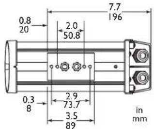
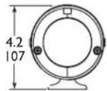
II"LHousing(NonHeaterVersions)


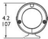
16"LHousing(HeaterandBlowerVersions)
DimensionalOutlinesMounts

Feed-throughMount
30-cm(12-in)Indoor/Outdoor
Feed-throughMount
MaximumLoad:9kg(20lb).
MountingHead:Adjustable.360°pan,180°tilt.
Approx.Weight:0.4kg(0.9lb).
WARNING: Allmountsmustbemountedasshown.

Feed-throughMount
18-cm(7-in)Indoor/Outdoor
MaximumLoad:9kg(20lb).
MountingHead:Adjustable.360°pan,180°tilt.
Finish:Darkmushroom.
Approx.Weight:0.3kg(0.7lb).
AccessoryforMT9215S:MT9213PoleMountAdapter.
WARNING: Allmountsmustbemountedasshown.
Ikegami
©2008Ikegami
Ikegami
263 | Manhattan Beach Blvd.
RedondoBeach, CA90278
Tel:310-297-1900
Fax:310-536-9550
www.ikegami.com
Datasubjecttochangewithoutnotice
1000225000IIKEI I/08
PrintedinU.S.A.


- IMPORTANTSAFEGUARDS
- SAFETY PRECAUTIONS
- CAUTION
- SECURITE
- ATTENTION
- U N P A C K I N G 5.1ModelDesignation
- 2ACCESSORIES
- Sunshields
- 3SERVICE
- 4CAREANDMAINTENANCE
- 5INSTALLATION
- ToolsRequired
- Cable Requirements
- VideoTransmission(Coaxial)
- InputPowerCord-NorthAmerican
- InputPowerCord-European
- LensControlCable
- HousingMountDescription
- Feed-throughMount.
- Attaching the Housing to the Mount
- InstallationoftheMount
- CoverRemoval
- 5.9Camera/LensInstallation
- MountingfixedlenscamerasinHousings
- Camera/LensWiring
- Conduit
- Feed-through Wiring
- Power Connections
- RecommendedMaximumCableLengthsforHousings Equippedwith24VoltCameras,Heaters,and Blowers
- WireSizeHousingDistance mm 2 AWGmetersfeet
- VideoCoaxConnection
- Lens Wiring
- 5.12Camera/LensAdjustment
- 5.13FinalAssembly
- 5.14FuseReplacement
- DimensionalOutlinesHousings
- Feed-throughMount
- 30-cm(12-in)Indoor/Outdoor
- 18-cm(7-in)Indoor/Outdoor
- Ikegami
Brand : Ikegami
Model : PAC-508
Category : Surveillance Camera