
DEH-P90DAB - Car stereo PIONEER - Free user manual and instructions
Find the device manual for free DEH-P90DAB PIONEER in PDF.
Download the instructions for your Car stereo in PDF format for free! Find your manual DEH-P90DAB - PIONEER and take your electronic device back in hand. On this page are published all the documents necessary for the use of your device. DEH-P90DAB by PIONEER.
USER MANUAL DEH-P90DAB PIONEER
- Contents Connecting the Units p. 2
- Installation p. 6
- Installation with the rubber bush p. 7
- Removing the Unit p. 8
- Installing the Steering Remote Control Unit p. 9
- Installing the Unit on a Left-Hand-Drive Car p. 10
Connecting the Units Note:
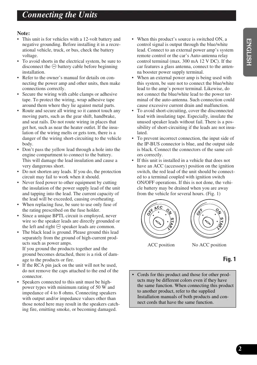
STAR STAR No ACC position ITALIANO
- When this product’s source is switched ON, a control signal is output through the blue/white lead. Connect to an external power amp’s system remote control or the car’s Auto-antenna relay control terminal (max. 300 mA 12 V DC). If the car features a glass antenna, connect to the antenna booster power supply terminal.
- When an external power amp is being used with this system, be sure not to connect the blue/white lead to the amp’s power terminal. Likewise, do not connect the blue/white lead to the power terminal of the auto-antenna. Such connection could cause excessive current drain and malfunction.
- To avoid short-circuiting, cover the disconnected lead with insulating tape. Especially, insulate the unused speaker leads without fail. There is a possibility of short-circuiting if the leads are not insulated.
- To prevent incorrect connection, the input side of the IP-BUS connector is blue, and the output side is black. Connect the connectors of the same colors correctly.
- If this unit is installed in a vehicle that does not have an ACC (accessory) position on the ignition switch, the red lead of the unit should be connected to a terminal coupled with ignition switch ON/OFF operations. If this is not done, the vehicle battery may be drained when you are away from the vehicle for several hours. (Fig. 1)
- Cords for this product and those for other products may be different colors even if they have the same function. When connecting this product to another product, refer to the supplied Installation manuals of both products and connect cords that have the same function. NEDERLANDS
- This unit is for vehicles with a 12-volt battery and negative grounding. Before installing it in a recreational vehicle, truck, or bus, check the battery voltage.
- To avoid shorts in the electrical system, be sure to disconnect the ≠ battery cable before beginning installation.
- Refer to the owner’s manual for details on connecting the power amp and other units, then make connections correctly.
- Secure the wiring with cable clamps or adhesive tape. To protect the wiring, wrap adhesive tape around them where they lie against metal parts.
- Route and secure all wiring so it cannot touch any moving parts, such as the gear shift, handbrake, and seat rails. Do not route wiring in places that get hot, such as near the heater outlet. If the insulation of the wiring melts or gets torn, there is a danger of the wiring short-circuiting to the vehicle body.
- Don’t pass the yellow lead through a hole into the engine compartment to connect to the battery. This will damage the lead insulation and cause a very dangerous short.
- Do not shorten any leads. If you do, the protection circuit may fail to work when it should.
- Never feed power to other equipment by cutting the insulation of the power supply lead of the unit and tapping into the lead. The current capacity of the lead will be exceeded, causing overheating.
- When replacing fuse, be sure to use only fuse of the rating prescribed on the fuse holder.
- Since a unique BPTL circuit is employed, never wire so the speaker leads are directly grounded or the left and right ≠ speaker leads are common.
- The black lead is ground. Please ground this lead separately from the ground of high-current products such as power amps. If you ground the products together and the ground becomes detached, there is a risk of damage to the products or fire.
- If the RCA pin jack on the unit will not be used, do not remove the caps attached to the end of the connector.
- Speakers connected to this unit must be highpower types with minimum rating of 50 W and impedance of 4 to 8 ohms. Connecting speakers with output and/or impedance values other than those noted here may result in the speakers catching fire, emitting smoke, or becoming damaged.
Connecting the Units 7 Basic Connection Note: Depending on the kind of vehicle, the function of 3* and 5* may be different. In this case, be sure to connect 2* to 5* and 4* to 3*. Multi-CD player (sold separately) 15 cm
DAB antenna Use only Pioneer product (e.g. AN-70DAB or AN-75DAB). If not, it may cause malfunction.
Connect leads of the same color to each other. Yellow (3*) Back-up (or accessory) Yellow (2*) To terminal always supplied with power regardless of ignition switch position. Red (5*) Accessory (or back-up) Fuse resistor Red (4*) To electric terminal controlled by ignition switch (12 V DC) ON/OFF. Orange/white To lighting switch terminal. Fuse holder Fuse resistor Black (ground) To vehicle (metal) body. ISO connector Note: In some vehicles, the ISO connector may be divided into two. In this case, be sure to connect to both connectors.
Yellow/black If you use a cellular telephone, connect it via the Audio Mute lead on the cellular telephone. If not, keep the Audio Mute lead free of any connections. ASL unit ENGLISH RCA output Refer to “Connecting to a Sold Separately Power Amp”. IP-BUS input (Blue) IP-BUS cable 15 cm 45 cm ESPAÑOL This Product 15 cm DEUTSCH Blue/white To system control terminal of the power amp (max. 300 mA 12 V DC). Refer to “Connecting to a Sold Separately Power Amp”. FRANÇAIS The pin position of the ISO connector will differ depends on the type of vehicle. Connect 6* and 7* when Pin 5 is an antenna control type. In another type of vehicle, never connect 6* and 7*. Blue/white (7*) To Auto-antenna relay control terminal (max. 300 mA 12 V DC). NEDERLANDS Note: When a subwoofer is connected to this unit instead of a rear right speaker, do not connect the rear left speaker lead to anything. For details, refer to the Initial Setting Menu in the Operation Manual. Fig. 2
Connecting the Units 7 Connecting to a Sold Separately Power Amp This product can be connected to a sold separately power amp using the RCA output jacks. Front output Connecting cords with RCA pin plugs (sold separately) Power amp (sold separately) Rear output Power amp (sold separately) This Product Power amp (sold separately) Subwoofer or Non-Fading output Blue/white To system control terminal of the power amp (max. 300 mA 12 V DC). System remote control Left Right
Subwoofer Subwoofer Left Right Rear speaker Rear speaker Left Right Front speaker Front speaker Fig. 3
- If installation angle exceeds 60° from horizontal, the unit might not give its optimum performance. (Fig. 4) ENGLISH 60° ESPAÑOL Fig. 4
- The cords must not cover up the area shown in the figure below. This is necessary to allow the amplifiers to radiate freely. (Fig. 5) DEUTSCH
- Before finally installing the unit, connect the wiring temporarily, making sure it is all connected up properly, and the unit and the system work properly.
- Use only the parts included with the unit to ensure proper installation. The use of unauthorized parts can cause malfunction.
- Consult with your nearest dealer if installation requires the drilling of holes or other modifications of the vehicle.
- Install the unit where it does not get in the driver’s way and cannot injure the passenger if there is a sudden stop, like an emergency stop.
- The semiconductor laser will be damaged if it overheats, so don’t install the unit anywhere hot — for instance, near a heater outlet.
- To prevent the ASL unit hanging from the main unit from scratching the main unit or your car console, it is wrapped in bubble packaging. When installing, be sure to first remove the bubble packaging to assure the unit functions correctly.
- When connecting a DAB antenna to this unit, use only a Pioneer product such as the AN-70DAB or AN-75DAB (sold separately). If not, it may cause malfunction. Do not close this area. FRANÇAIS Fig. 5 ITALIANO NEDERLANDS
Installation Installation with the rubber bush Dashboard
Holder After inserting the holder into the dashboard, then select the appropriate tabs according to the thickness of the dashboard material and bend them. (Install as firmly as possible using the top and bottom tabs. To secure, bend the tabs 90 degrees.) Rubber bush Screw Fig. 6
Removing the Unit ENGLISH Frame ESPAÑOL Pull out to remove the frame. (When reattaching the frame, point the side with a groove downwards and attach it.) Fig. 7 DEUTSCH Insert the supplied extraction keys into the unit, as shown in the figure, until they click into place. Keeping the keys pressed against the sides of the unit, pull the unit out. FRANÇAIS Fig. 8 ITALIANO NEDERLANDS
Installing the Steering Remote Control Unit WARNING
- Avoid installing this unit in such a location where the operation of safety devices such as airbags is prevented by this unit. Otherwise, there is a danger of a fatal accident.
- Avoid installing this unit in such a location where the operation of the steering wheel and the gearshift lever may be prevented. Otherwise, it may result in a traffic accident. Note:
- Do not install this unit in such a place as may obstruct the driver’s view.
- Since interior layout differs depending on the type of vehicle, the ideal installation location for the unit also differs. When installing the unit, select a location that assures optimum transmission of signals from the unit to the car stereo. CAUTION
- Installation of this unit requires specialized skills and experience. Installation of this unit should be entrusted to a dealer from whom you purchased this unit.
- Install this unit using only the parts supplied with this unit. If other parts are used, this unit may be damaged or could dismount itself, which leads to an accident or trouble.
- Install this unit as required by this manual. Failure to do so may cause an accident.
- Do not install this unit near the doors where rainwater is likely to be spilled on the unit. Incursion of water into the unit may cause smoke or fire. WARNING
- Fix this unit securely to the steering wheel with the belt attached to the unit. If this unit is loose, it disturbs driving stability, which may result in a traffic accident.
- Do not attach this unit to the outer circumference of the steering wheel. Otherwise, it disturbs driving stability, causing a traffic accident. Always attach this unit to the inner circumference of the steering wheel as shown. (Fig. 9) Fig. 9
- When the unit is installed on a right-hand-drive car, the horizontal positions are inverted.
- Fit the inner holder to the steering wheel so that the arrow-marked side faces the driver as shown below. Inner holder
- Tighten the screws with the supplied hexagonal wrench. Screw ESPAÑOL
1. Secure inner holder to the inner circumference of the steering wheel
with belt. (Fig. 10)
3. Install outer holder on the inner
holder and secure with screws. (Fig. 12) ENGLISH Installing the Unit on a Left-Hand Drive Car Outer holder DEUTSCH Belt Fig. 12
4. Install the remote control unit in
the holder. (Fig. 13) FRANÇAIS Fig. 10
- When removing the remote control unit from the holder, move the corrugated release section toward the steering wheel and slide the remote control unit toward you.
2. Cut the extra portion of the belt at
the center of the inner holder. (Fig. 11)
- Keep the cut-off portion of the belt as a spare. ITALIANO NEDERLANDS Release Section Fig. 13 Fig. 11
Aucune position ACC Fig. 1 NEDERLANDS France: tapez 36 15 PIONEER PIONEER CORPORATION 4-1, MEGURO 1-CHOME, MEGURO-KU, TOKYO 153-8654, JAPAN PIONEER ELECTRONICS (USA) INC. P.O. Box 1760, Long Beach, California 90801, U.S.A. TEL: (800) 421-1404
PIONEER EUROPE NV
Haven 1087, Keetberglaan 1, B-9120 Melsele, Belgium TEL: (0) 3/570.05.11 PIONEER ELECTRONICS AUSTRALIA PTY. LTD. 178-184 Boundary Road, Braeside, Victoria 3195, Australia TEL: (03) 9586-6300 PIONEER ELECTRONICS OF CANADA, INC. 300 Allstate Parkway, Markham, Ontario L3R OP2, Canada TEL: (905) 479-4411 PIONEER ELECTRONICS DE MEXICO, S.A. de C.V. San Lorenzo 1009 3er, Piso Desp. 302 Col. Del Valle Mexico, D.F. C.P. 03100
TEL: 5-688-52-90
Published by Pioneer Corporation. Copyright © 2000 by Pioneer Corporation. All rights reserved. Publication de Pioneer Corporation. Copyright © 2000 Pioneer Corporation. Tous droits de reproduction et de traduction réservés. Printed in Japan Imprimé au Japon <KSNFF/00H00000>